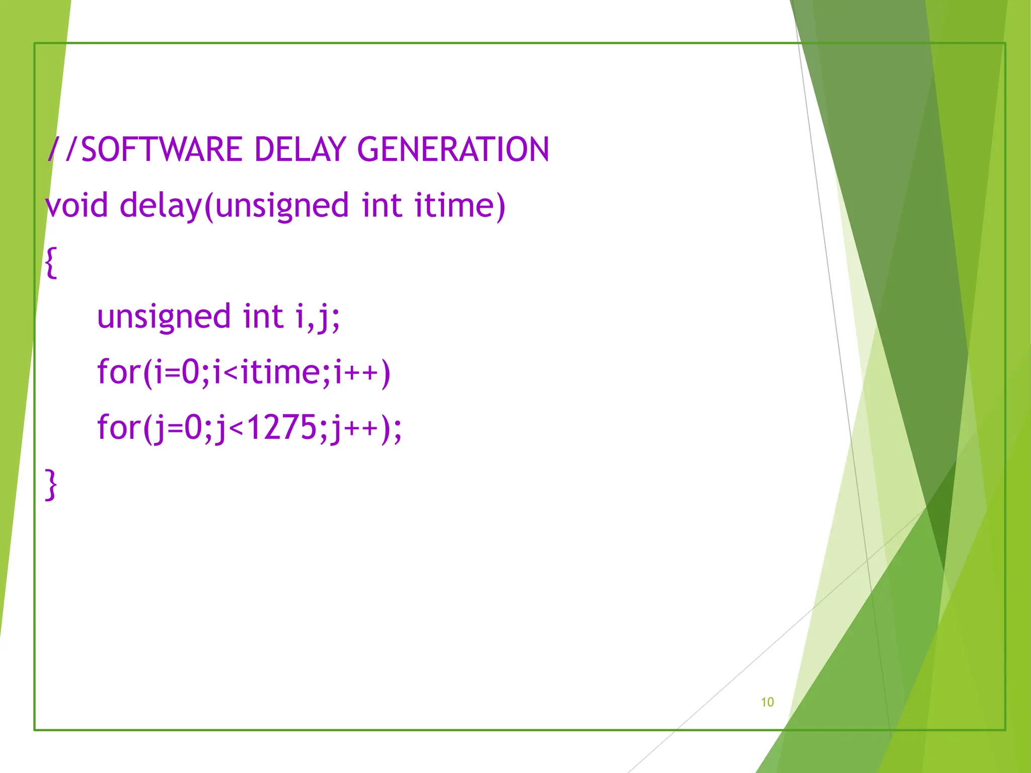
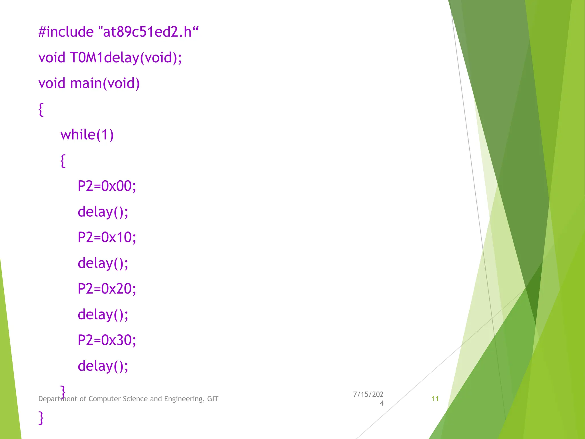
Experiment No. 1
PROBLEM DEFINITION: To implement MOD-4 counter on
LEDs connected to Port 2 using
i) Software delay
ii) Hardware delay
1
Objectives of the Experiment:
1. To demonstrate the interfacing of LEDs
connected to Port2 of 8051 Microcontroller.
2. To develop an 8051 ‘C’ code to display the MOD-4
count 00,01,10,11 on LEDs connected to Port2
2
MOD-4 Counter
Implementation
 MOD-4 counter has four count states
00,01,10,11.
 Two LEDs are connected to Port 2 pins 4 and
5.
 To display the count 00, 01,10,11 on LEDs
Port 2 is loaded with the data 0x00,
0x10,0x20, 0x30 respectively.
3
Delay Generation using
software
 Delay can be generated by for loop
Example: The delay routine shown below
generates 250 milliseconds of time delay(for
itime=250)
void delay(unsigned int itime)
{
unsigned int i,j;
for(i=0;i<itime;i++)
for(j=0;j<1275;j++);
}
4
Delay Generation using
Hardware
 Delay can be generated by
Hardware(Timer)
 Example: 50ms Time delay
generation using Timer 0 in Mode 1
5
Delay Generation using
Hardware
void T0M1Delay(void)
{
TMOD=0X01; //TIMER 0 MODE 1(16-BIT MODE)
TL0= 0XFE; // LOAD TL0 WITH COUNT 0FE
TH0=0X4B; // LOAD TH0 WITH COUNT 4B
TR0=1; // START TIMER
while(TF0==0); //WAIT FOR TF0 TO ROLL OVER
TR0=0; //TURN OFF T0
TF0=0; // CLEAR TF0
}
6
INTERFACING BLOCK DIAGRAM
7/15/202
4
Department of Computer Science and Engineering, GIT 7
8051
MICROCONTROLLER
P2.4
P2.5
LED0
LED1
Algorithm for the experiment
STEP 1 : INCLUDE THE HEADER FILE ‘’at89c51ed2.h’’
STEP 2 : DECLARE THE DELAY ROUTINE (CASE1: SOFTWARE DELAY,
CASE 2: HARDWARE DELAY)
STEP 3 : DECLARE VARIABLES i, j, itime
STEP 4 : BEGIN MAIN
STEP 5 : REPEAT LOOP FOREVER USING WHILE(1)
STEP 6: SEND THE VALUE 0X00, 0X10,0X20,0X30 ON P2
STEP 7: CALL DELAY BETWEEN EACH VALUE
STEP 8: END
8
#include "at89c51ed2.h“
void delay(unsigned int);
void main(void)
{
while(1)
{
P2=0x00;
delay(250);
P2=0x10;
delay(250);
P2=0x20;
delay(250);
P2=0x30;
delay(250);
}
}
9
//SOFTWARE DELAY GENERATION
void delay(unsigned int itime)
{
unsigned int i,j;
for(i=0;i<itime;i++)
for(j=0;j<1275;j++);
}
10
#include "at89c51ed2.h“
void T0M1delay(void);
void main(void)
{
while(1)
{
P2=0x00;
delay();
P2=0x10;
delay();
P2=0x20;
delay();
P2=0x30;
delay();
}
}
7/15/202
4
Department of Computer Science and Engineering, GIT 11
// HARDWARE DELAY GENERATION USING TIMER 0 IN MODE1
void T0M1Delay(void)
{
TMOD=0X01; //TIMER 0 MODE 1(16-BIT MODE)
TL0= 0XFE; // LOAD TL0 WITH COUNT 0FE
TH0=0X4B; // LOAD TH0 WITH COUNT 4B
TR0=1; // START TIMER
while(TF0==0); //WAIT FOR TF0 TO ROLL OVER
TR0=0; //TURN OFF T0
TF0=0; // CLEAR TF0
}
7/15/202
4
Department of Computer Science and Engineering, GIT 12
Connection Details
• Port 2 to CN11 of Microcontroller
Evaluation Board.
13
Learning Outcomes of the Experiment
At the end of the session, students should be able to :
•Interface LEDs connected to Port 2 of 8051 Microcontroller
•Develop ‘C’ code to display the MOD-4 count 00, 01, 10, 11 on LEDs
connected to 8051 Microcontroller.
Inquiry based learning
 Interface 8051 with the LEDs connected to PORT 2.
 Develop the algorithm and 8051 Embedded ‘C’ program
to implement MOD-4 DOWN counter.
 Develop the algorithm and 8051 Embedded ‘C’ program
to implement 2 bit UP/DOWN counter.
7/15/202
4
Department of Computer Science and Engineering, GIT 15

MoD 4 Counters TermWork1MOD4Counter.pptx

  • 1.
    Experiment No. 1 PROBLEMDEFINITION: To implement MOD-4 counter on LEDs connected to Port 2 using i) Software delay ii) Hardware delay 1
  • 2.
    Objectives of theExperiment: 1. To demonstrate the interfacing of LEDs connected to Port2 of 8051 Microcontroller. 2. To develop an 8051 ‘C’ code to display the MOD-4 count 00,01,10,11 on LEDs connected to Port2 2
  • 3.
    MOD-4 Counter Implementation  MOD-4counter has four count states 00,01,10,11.  Two LEDs are connected to Port 2 pins 4 and 5.  To display the count 00, 01,10,11 on LEDs Port 2 is loaded with the data 0x00, 0x10,0x20, 0x30 respectively. 3
  • 4.
    Delay Generation using software Delay can be generated by for loop Example: The delay routine shown below generates 250 milliseconds of time delay(for itime=250) void delay(unsigned int itime) { unsigned int i,j; for(i=0;i<itime;i++) for(j=0;j<1275;j++); } 4
  • 5.
    Delay Generation using Hardware Delay can be generated by Hardware(Timer)  Example: 50ms Time delay generation using Timer 0 in Mode 1 5
  • 6.
    Delay Generation using Hardware voidT0M1Delay(void) { TMOD=0X01; //TIMER 0 MODE 1(16-BIT MODE) TL0= 0XFE; // LOAD TL0 WITH COUNT 0FE TH0=0X4B; // LOAD TH0 WITH COUNT 4B TR0=1; // START TIMER while(TF0==0); //WAIT FOR TF0 TO ROLL OVER TR0=0; //TURN OFF T0 TF0=0; // CLEAR TF0 } 6
  • 7.
    INTERFACING BLOCK DIAGRAM 7/15/202 4 Departmentof Computer Science and Engineering, GIT 7 8051 MICROCONTROLLER P2.4 P2.5 LED0 LED1
  • 8.
    Algorithm for theexperiment STEP 1 : INCLUDE THE HEADER FILE ‘’at89c51ed2.h’’ STEP 2 : DECLARE THE DELAY ROUTINE (CASE1: SOFTWARE DELAY, CASE 2: HARDWARE DELAY) STEP 3 : DECLARE VARIABLES i, j, itime STEP 4 : BEGIN MAIN STEP 5 : REPEAT LOOP FOREVER USING WHILE(1) STEP 6: SEND THE VALUE 0X00, 0X10,0X20,0X30 ON P2 STEP 7: CALL DELAY BETWEEN EACH VALUE STEP 8: END 8
  • 9.
    #include "at89c51ed2.h“ void delay(unsignedint); void main(void) { while(1) { P2=0x00; delay(250); P2=0x10; delay(250); P2=0x20; delay(250); P2=0x30; delay(250); } } 9
  • 10.
    //SOFTWARE DELAY GENERATION voiddelay(unsigned int itime) { unsigned int i,j; for(i=0;i<itime;i++) for(j=0;j<1275;j++); } 10
  • 11.
    #include "at89c51ed2.h“ void T0M1delay(void); voidmain(void) { while(1) { P2=0x00; delay(); P2=0x10; delay(); P2=0x20; delay(); P2=0x30; delay(); } } 7/15/202 4 Department of Computer Science and Engineering, GIT 11
  • 12.
    // HARDWARE DELAYGENERATION USING TIMER 0 IN MODE1 void T0M1Delay(void) { TMOD=0X01; //TIMER 0 MODE 1(16-BIT MODE) TL0= 0XFE; // LOAD TL0 WITH COUNT 0FE TH0=0X4B; // LOAD TH0 WITH COUNT 4B TR0=1; // START TIMER while(TF0==0); //WAIT FOR TF0 TO ROLL OVER TR0=0; //TURN OFF T0 TF0=0; // CLEAR TF0 } 7/15/202 4 Department of Computer Science and Engineering, GIT 12
  • 13.
    Connection Details • Port2 to CN11 of Microcontroller Evaluation Board. 13
  • 14.
    Learning Outcomes ofthe Experiment At the end of the session, students should be able to : •Interface LEDs connected to Port 2 of 8051 Microcontroller •Develop ‘C’ code to display the MOD-4 count 00, 01, 10, 11 on LEDs connected to 8051 Microcontroller.
  • 15.
    Inquiry based learning Interface 8051 with the LEDs connected to PORT 2.  Develop the algorithm and 8051 Embedded ‘C’ program to implement MOD-4 DOWN counter.  Develop the algorithm and 8051 Embedded ‘C’ program to implement 2 bit UP/DOWN counter. 7/15/202 4 Department of Computer Science and Engineering, GIT 15