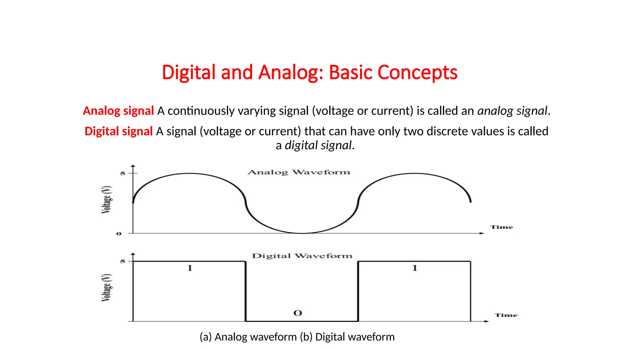
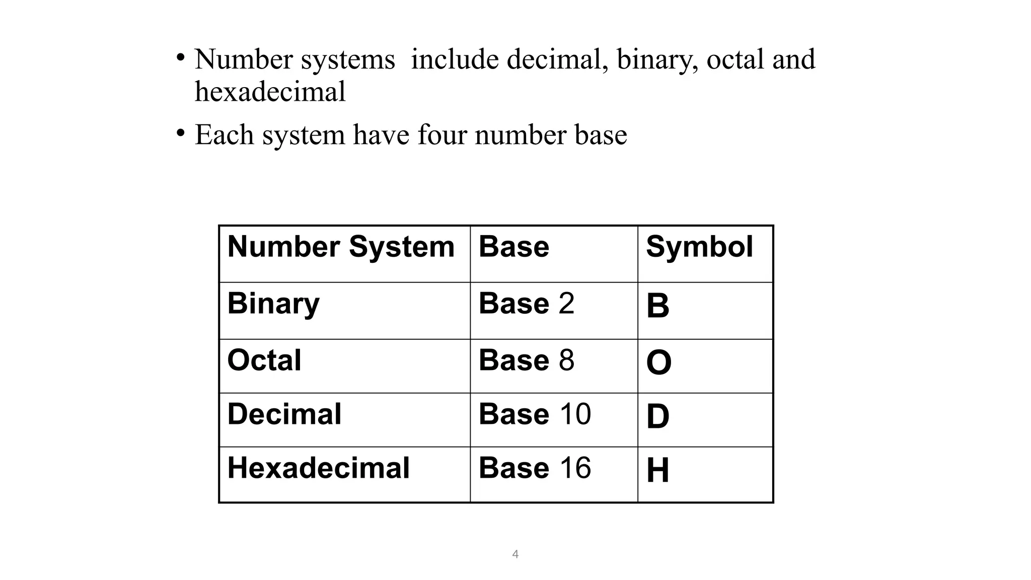
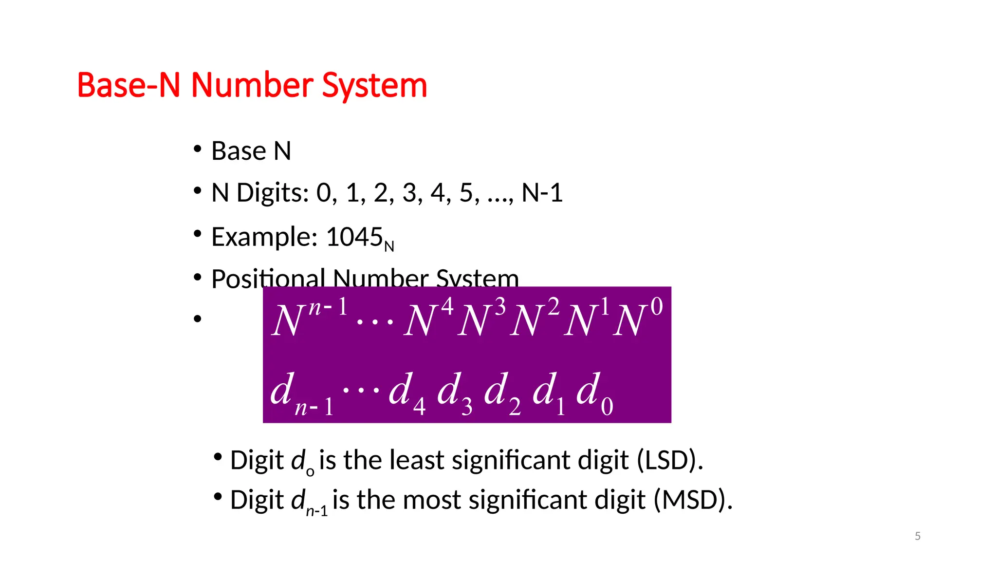
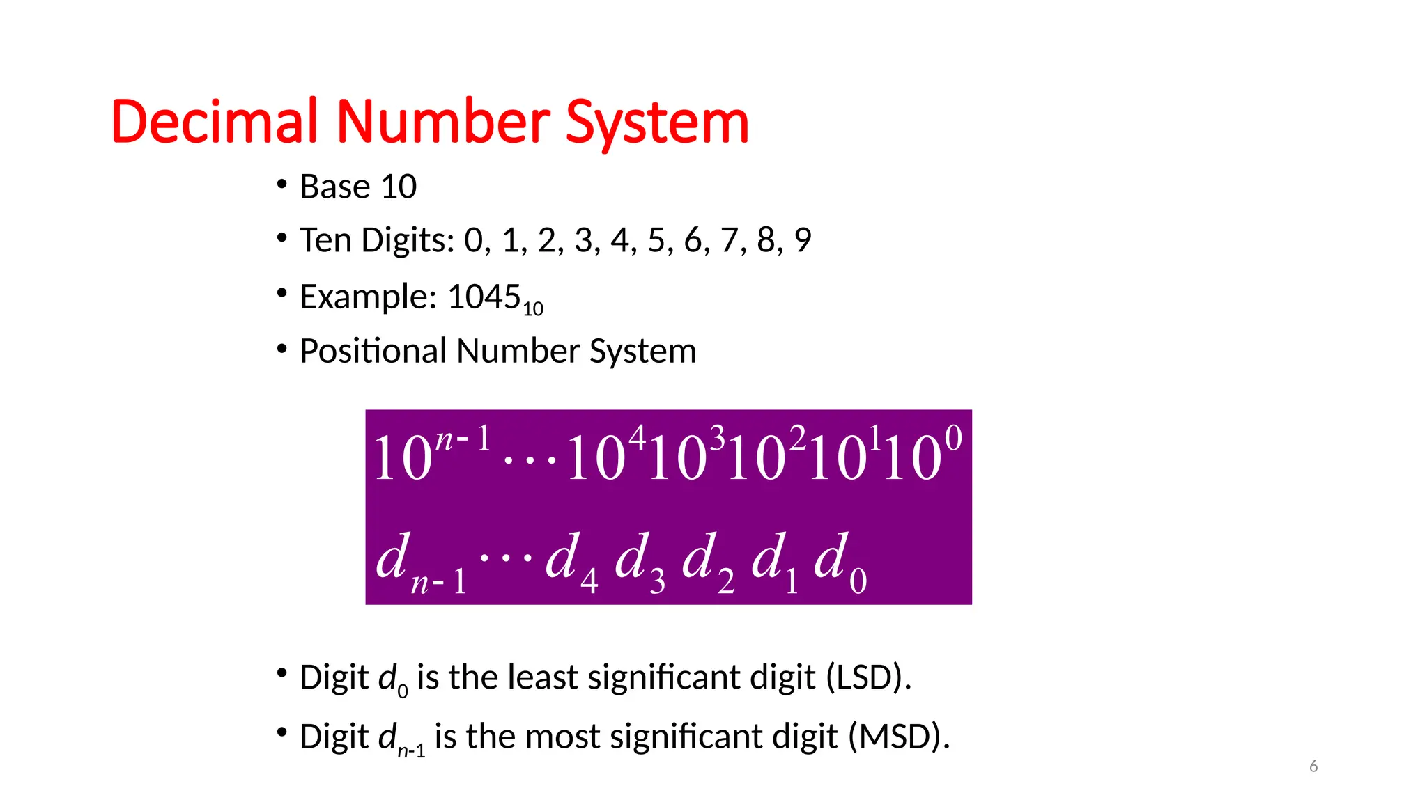
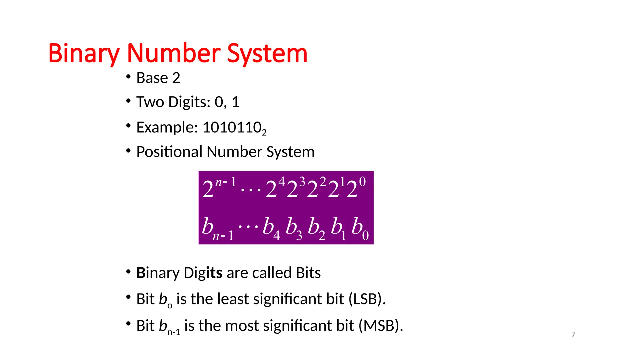
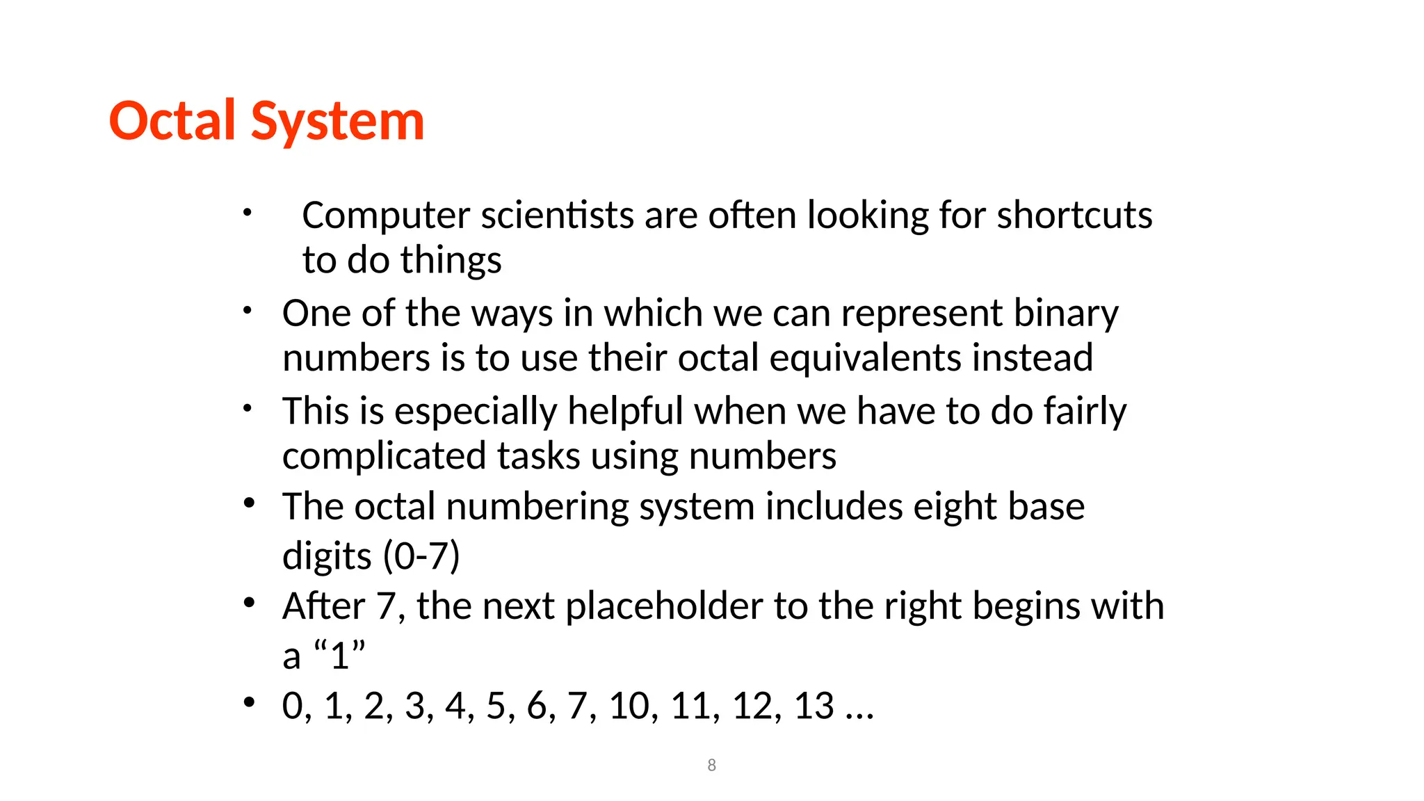
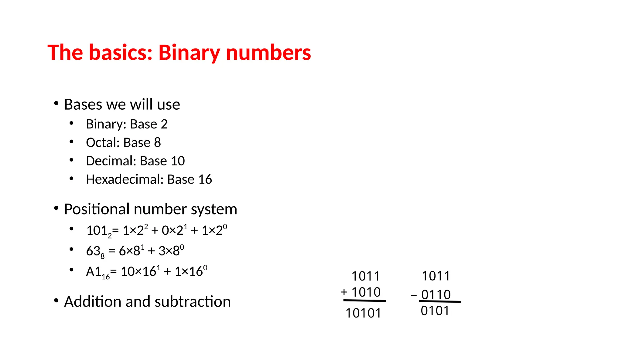
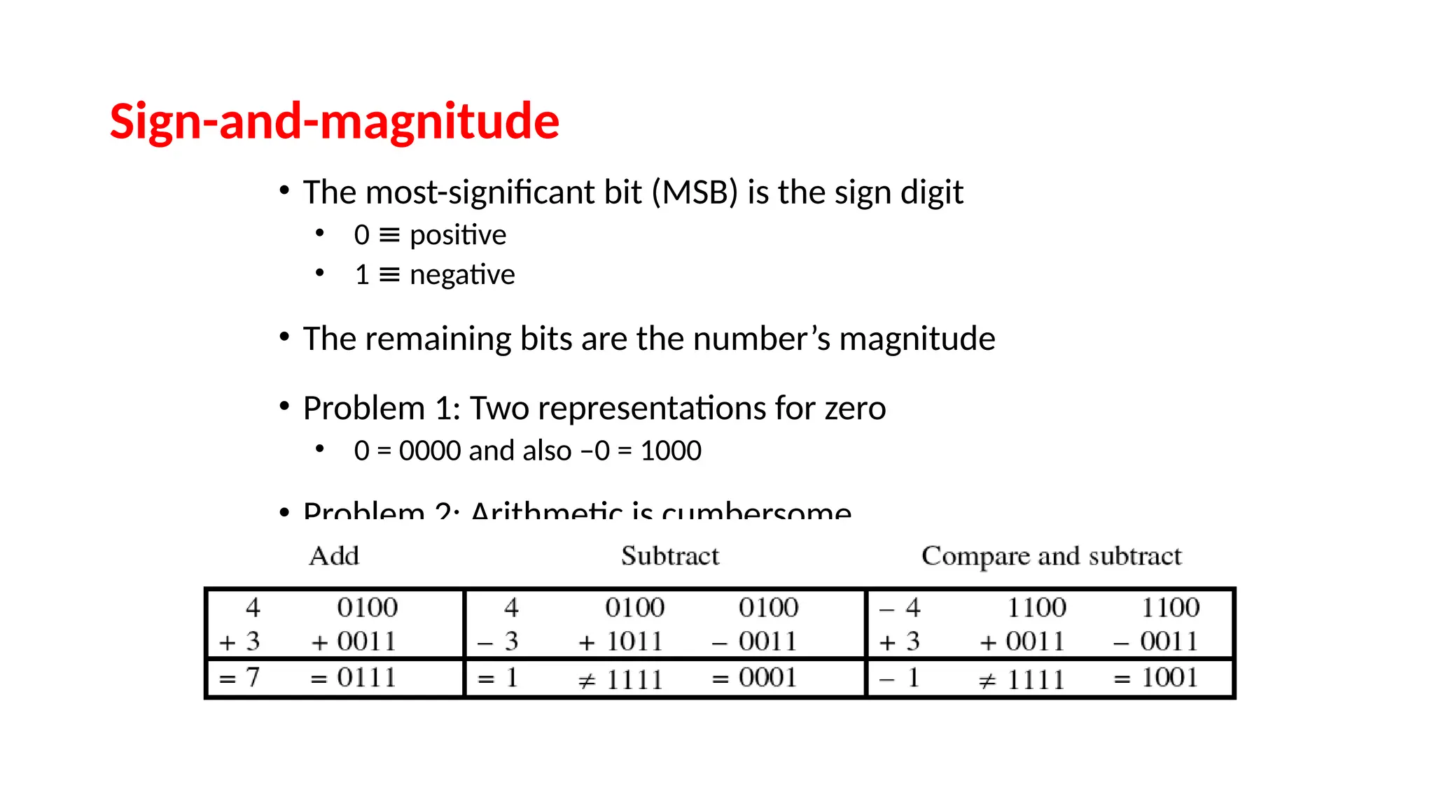
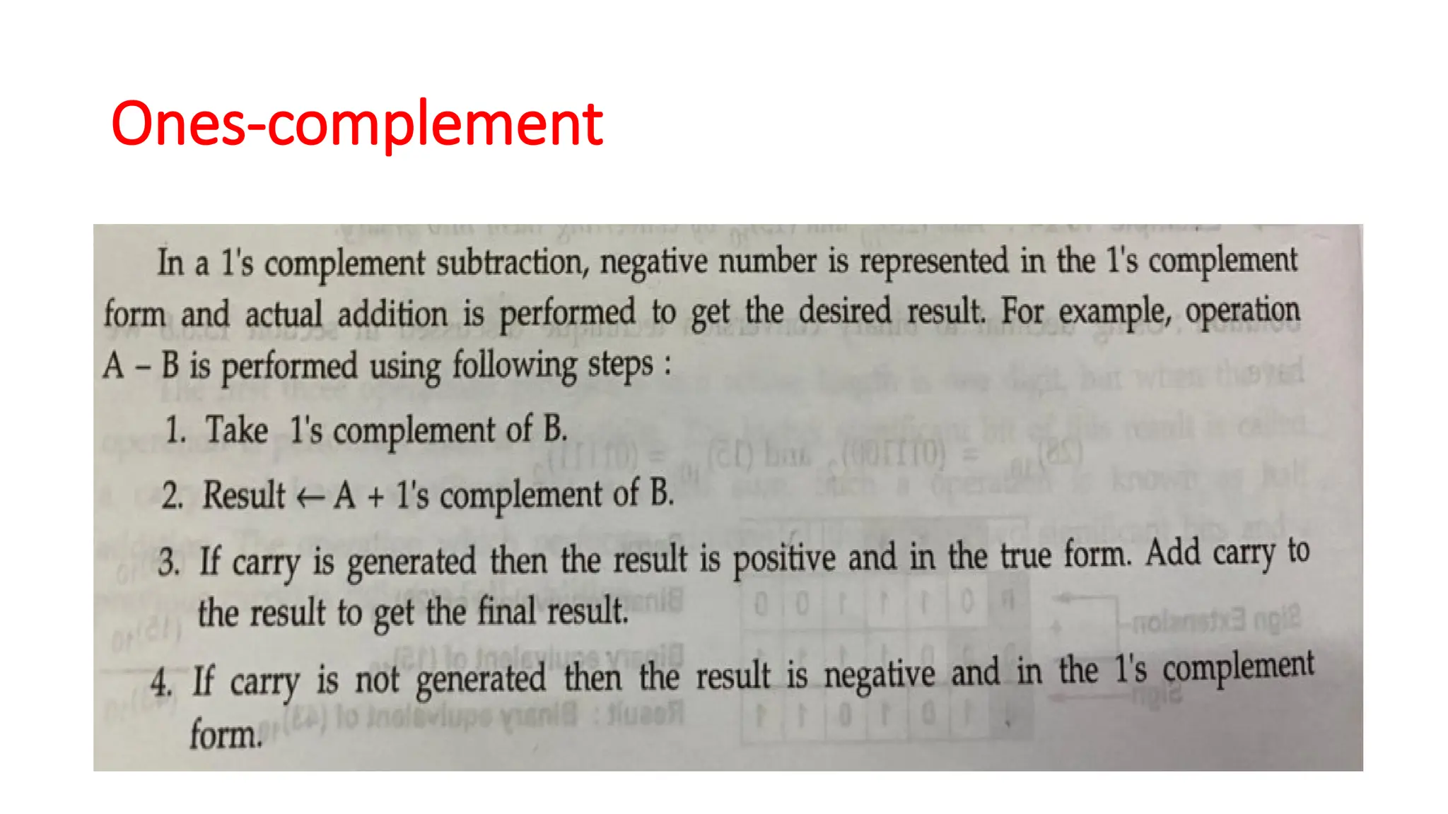
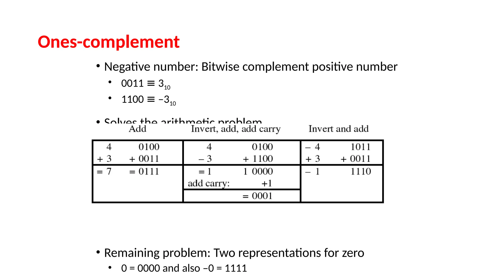
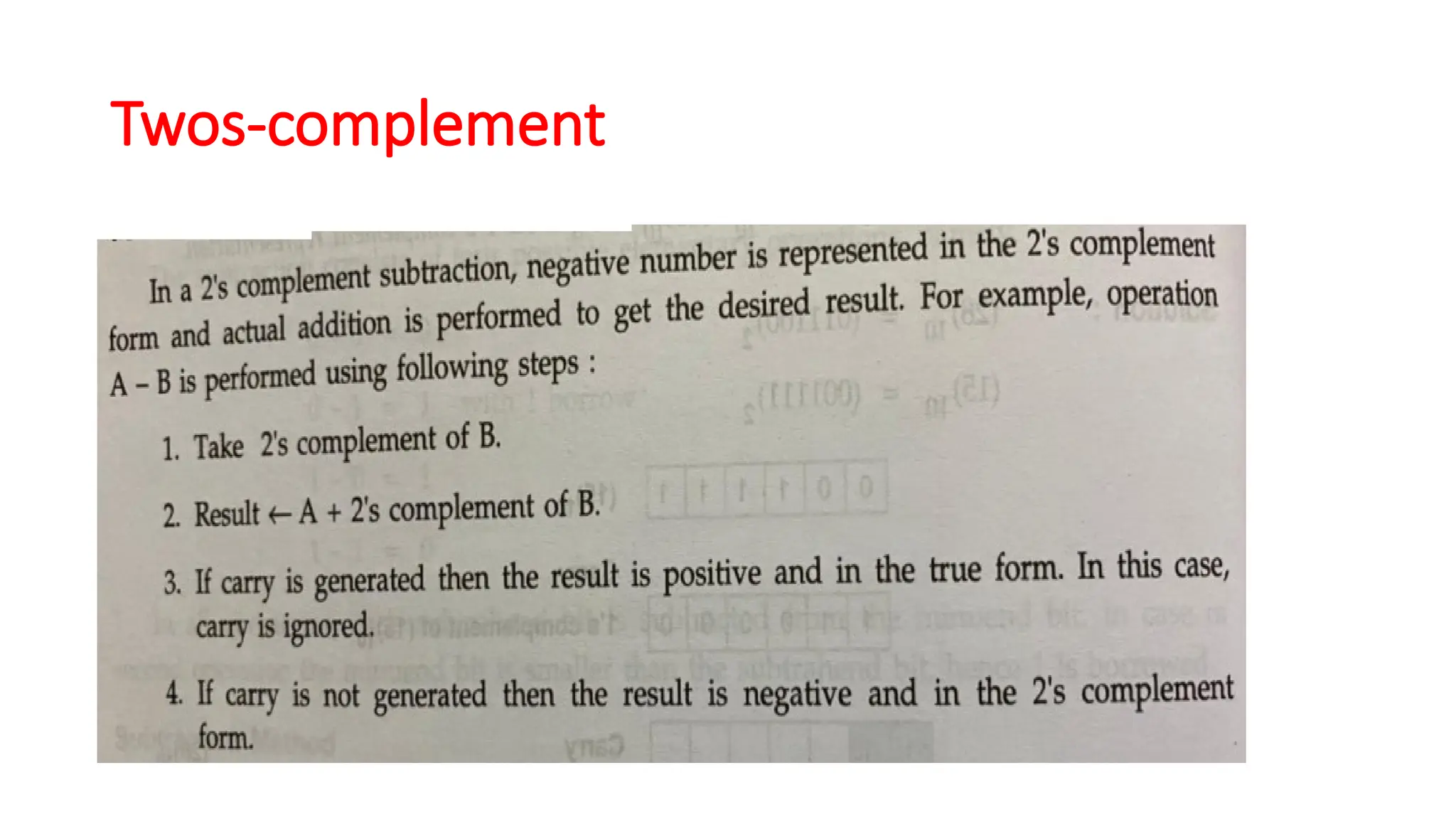
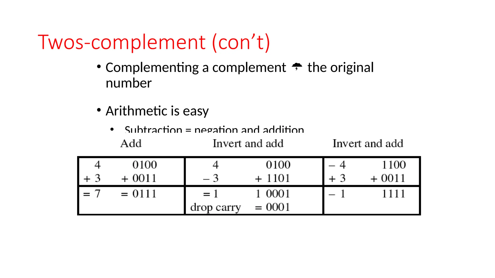
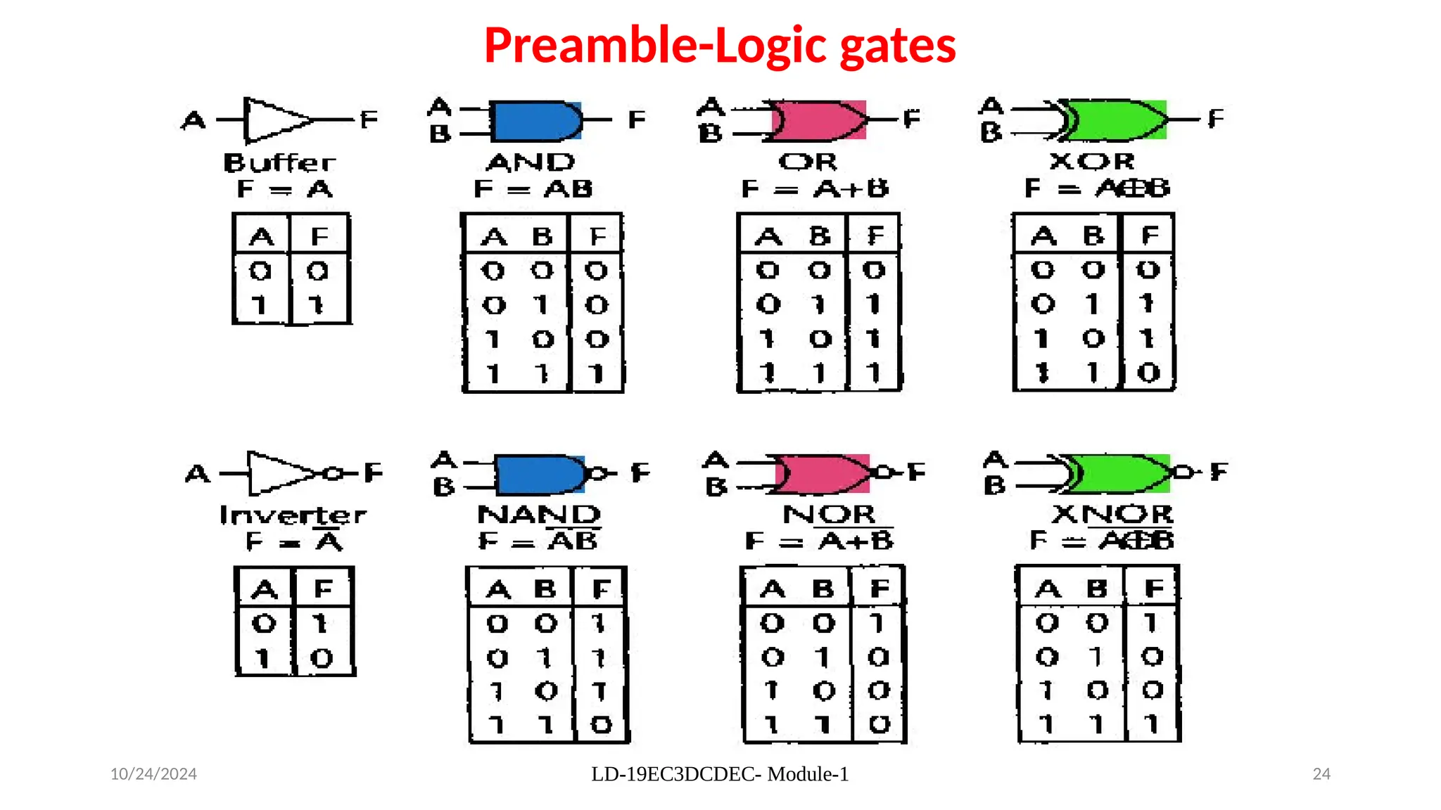
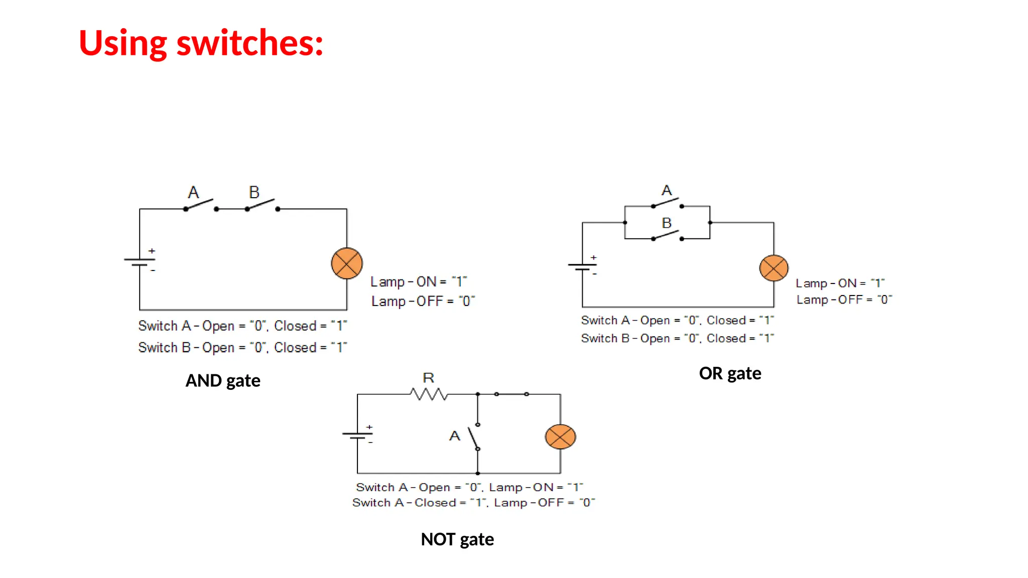
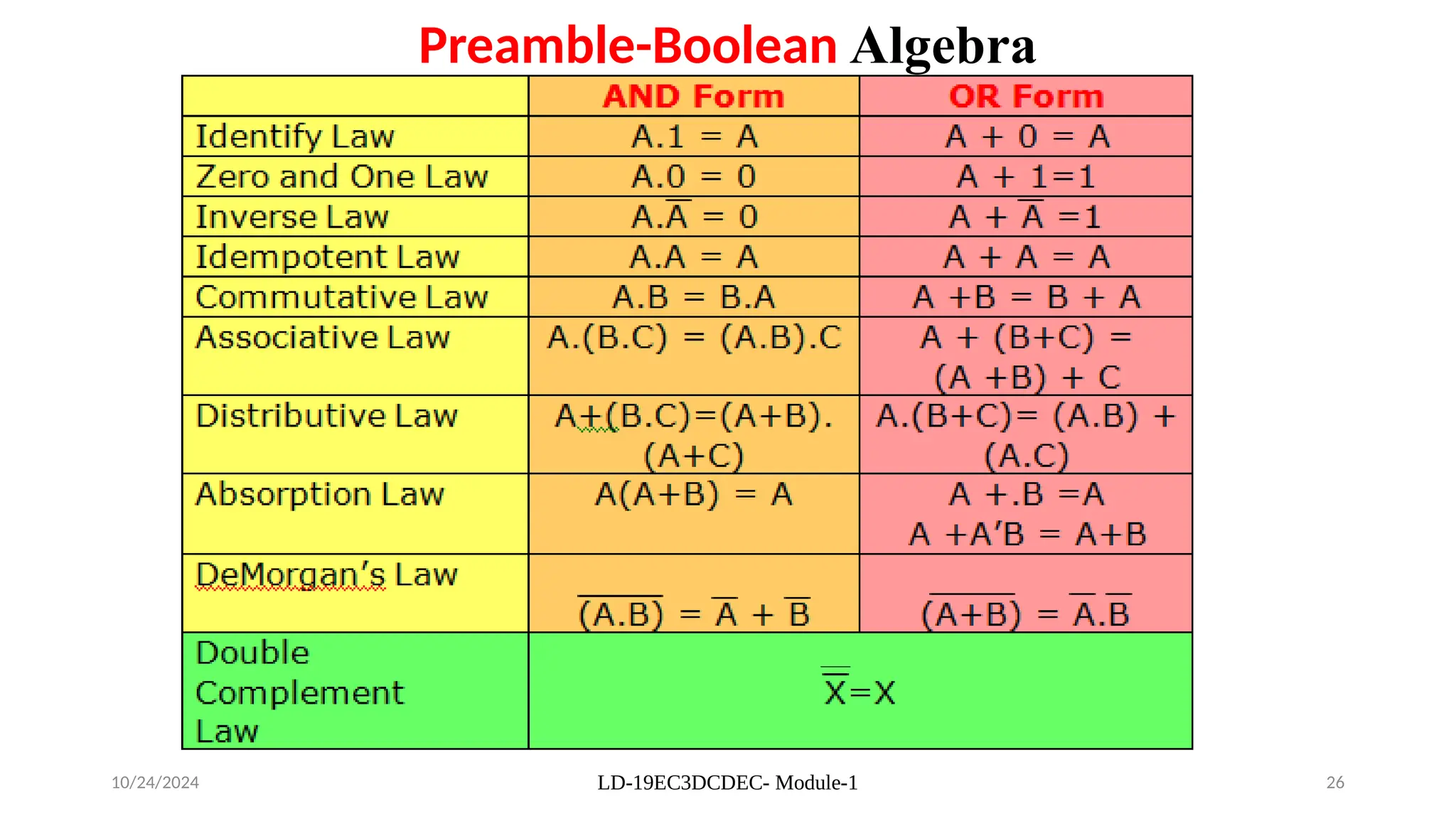
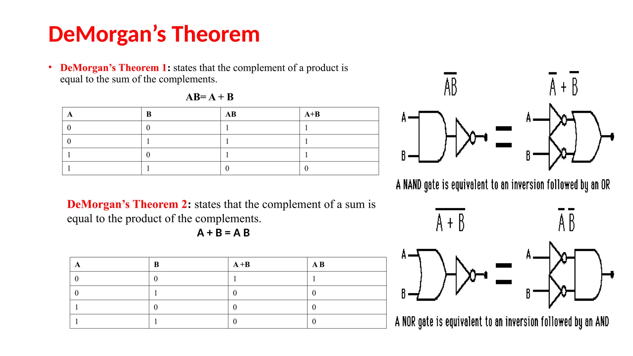
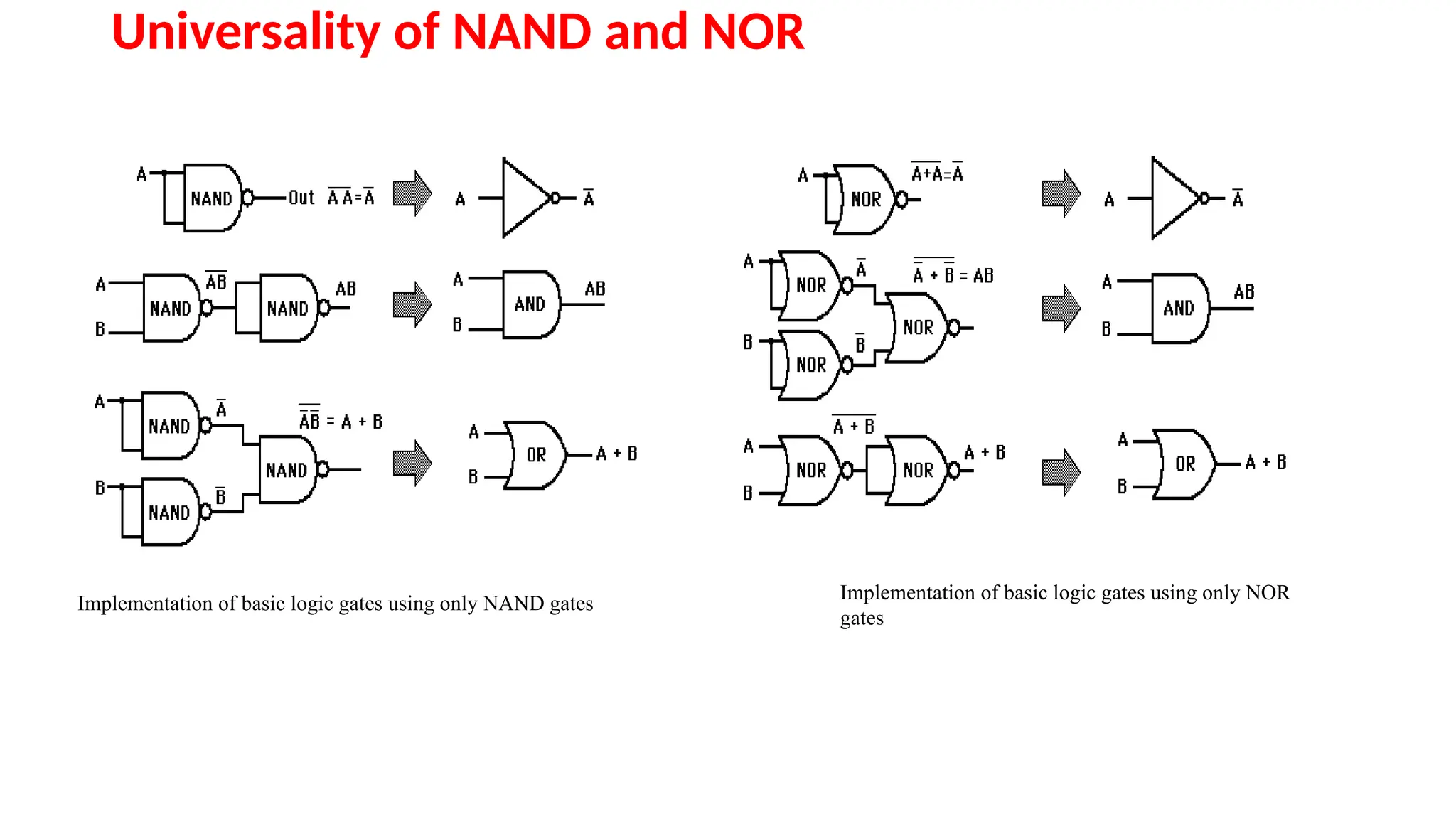
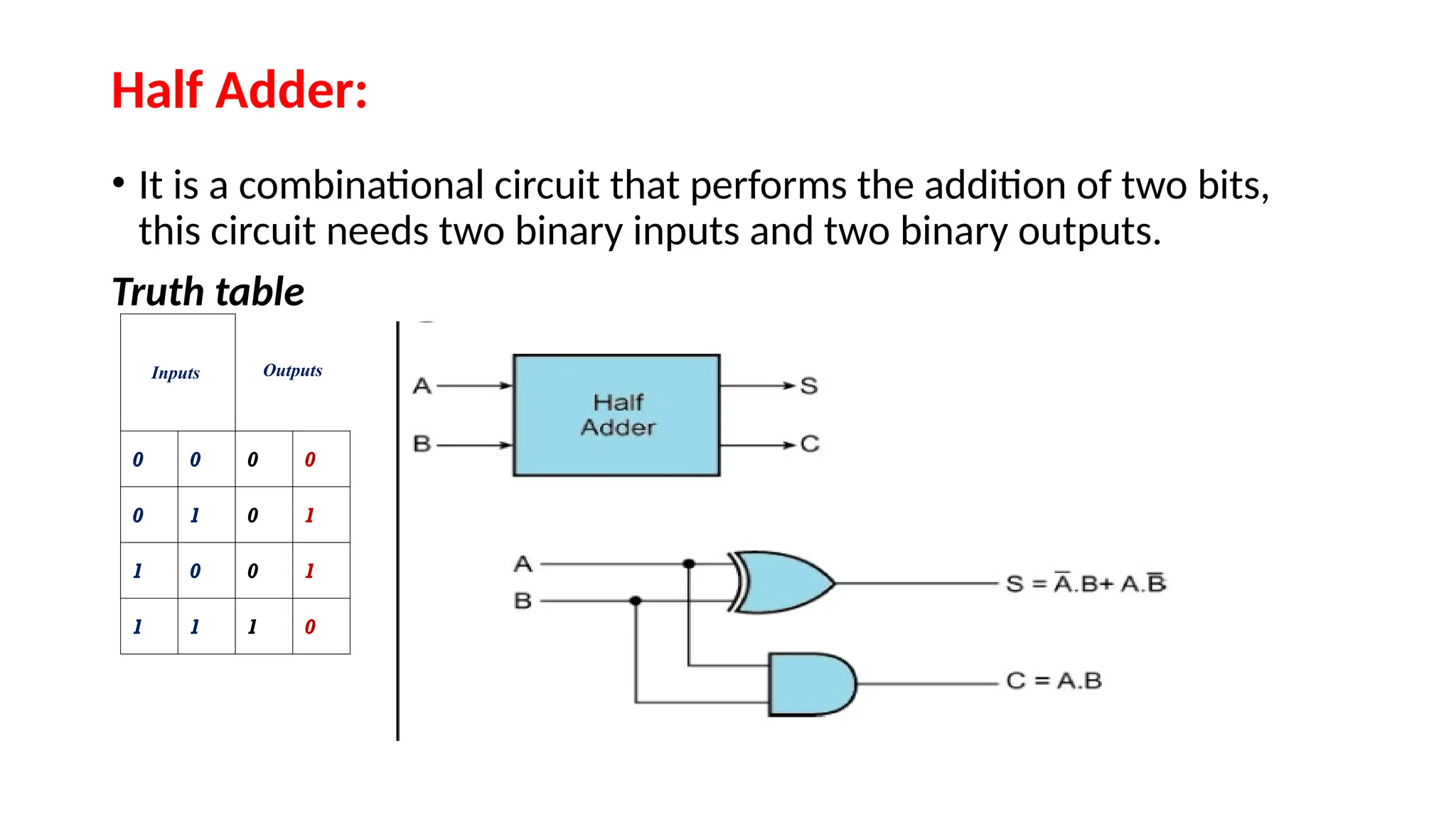
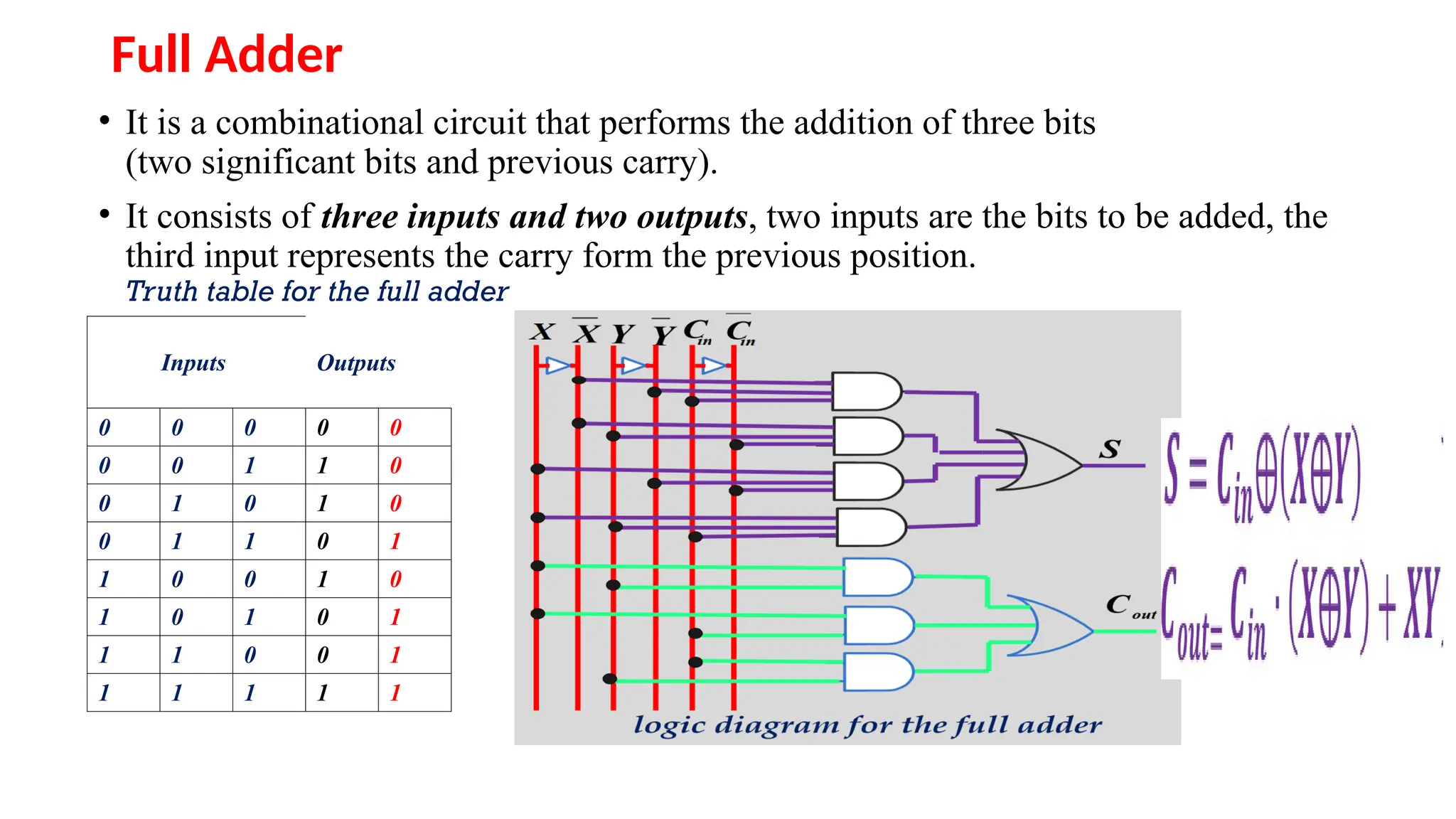
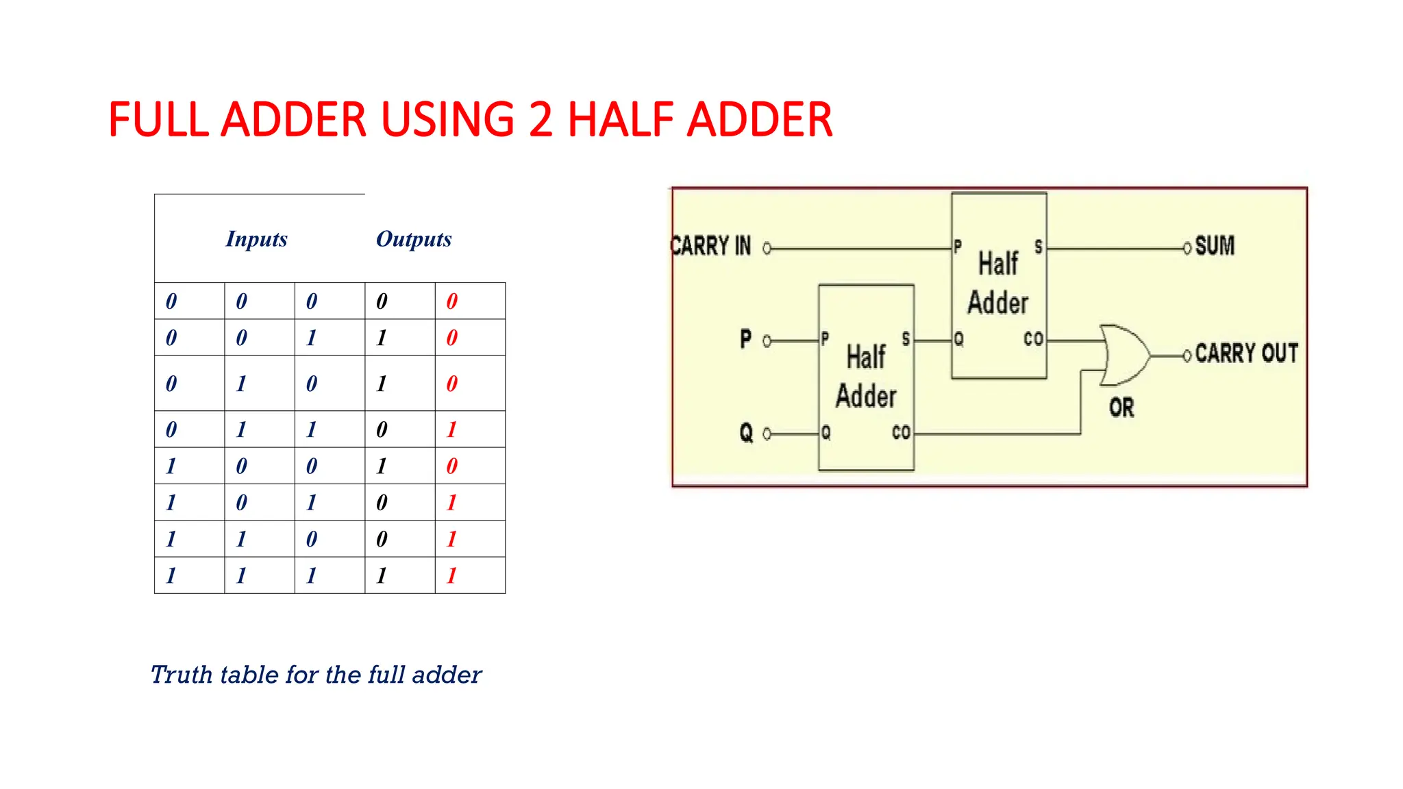
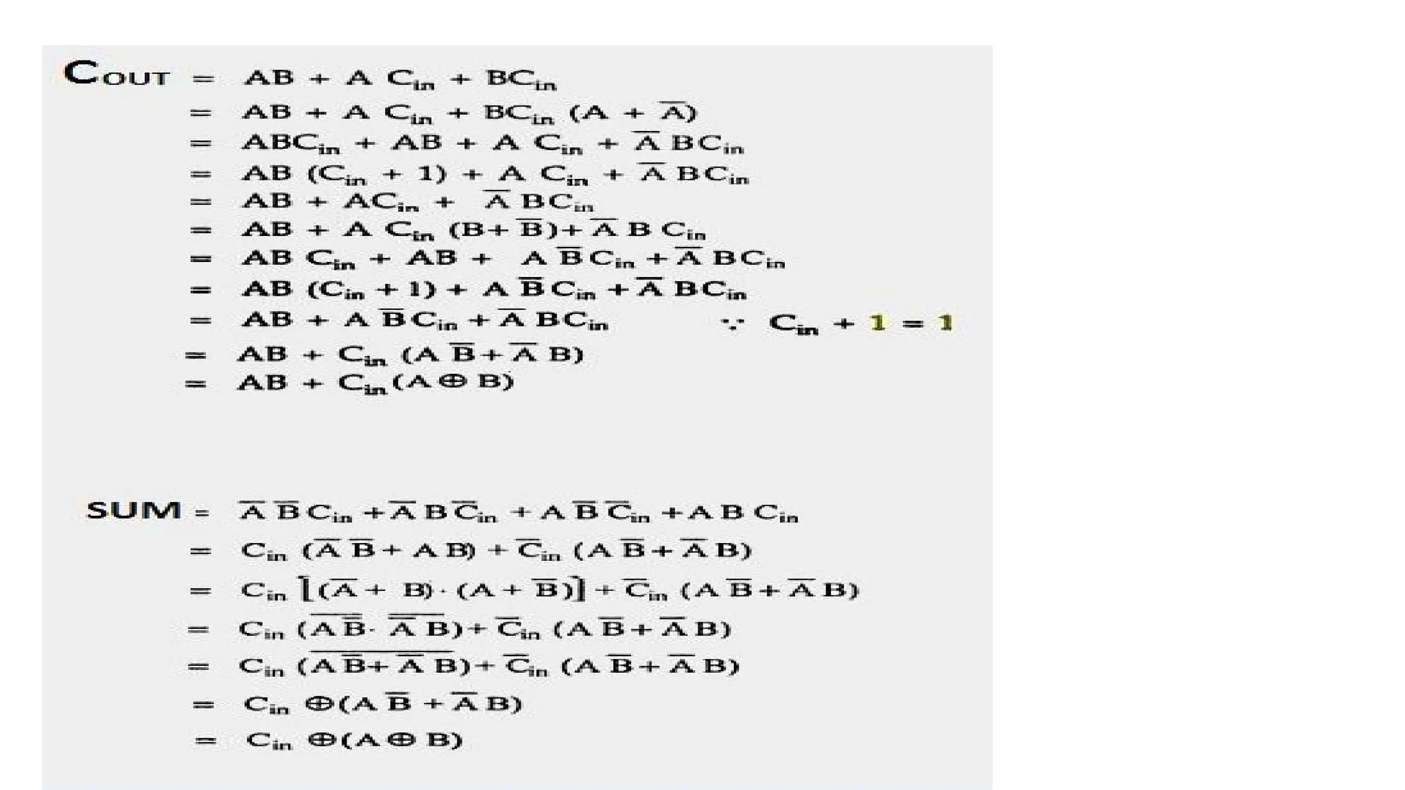
DEPARTMENT
OF
ELECTRONICS & COMMUNICATION ENGINEERING
BASIC ELECTRONICS
MODULE-1 Digital Electronics
BY
Prof M SHRUTHI
 Module – 1 Contents
 Digital Electronics 1
• Introduction to Number Systems
• Binary Number System
• Decimal Number System
• Octal Number System
• Hexadecimal Number System
• Conversion from one number system to another number system
• 1’s and 2’s complement method and their arithmetic
 Digital Electronics 2
• Binary logic functions
• Boolean algebra
• De-Morgan’s Theorem
• Logic gates
• Realization of Boolean functions using basic gates
• Implementation of logic gates as half & full adder
Digital and Analog: Basic Concepts
Analog signal A continuously varying signal (voltage or current) is called an analog signal.
Digital signal A signal (voltage or current) that can have only two discrete values is called
a digital signal.
(a) Analog waveform (b) Digital waveform
4
• Number systems include decimal, binary, octal and
hexadecimal
• Each system have four number base
Number System Base Symbol
Binary Base 2 B
Octal Base 8 O
Decimal Base 10 D
Hexadecimal Base 16 H
5
Base-N Number System
• Base N
• N Digits: 0, 1, 2, 3, 4, 5, …, N-1
• Example: 1045N
• Positional Number System
•
• Digit do is the least significant digit (LSD).
• Digit dn-1 is the most significant digit (MSD).
1 4 3 2 1 0
1 4 3 2 1 0
n
n
N N N N N N
d d d d d d




6
Decimal Number System
• Base 10
• Ten Digits: 0, 1, 2, 3, 4, 5, 6, 7, 8, 9
• Example: 104510
• Positional Number System
• Digit d0 is the least significant digit (LSD).
• Digit dn-1 is the most significant digit (MSD).
1 4 3 2 1 0
1 4 3 2 1 0
10 10 10 10 1010
n
n
d d d d d d




7
Binary Number System
• Base 2
• Two Digits: 0, 1
• Example: 10101102
• Positional Number System
• Binary Digits are called Bits
• Bit bo is the least significant bit (LSB).
• Bit bn-1 is the most significant bit (MSB).
1 4 3 2 1 0
1 4 3 2 1 0
2 2 2 2 2 2
n
n
b b b b b b




8
Octal System
• Computer scientists are often looking for shortcuts
to do things
• One of the ways in which we can represent binary
numbers is to use their octal equivalents instead
• This is especially helpful when we have to do fairly
complicated tasks using numbers
• The octal numbering system includes eight base
digits (0-7)
• After 7, the next placeholder to the right begins with
a “1”
• 0, 1, 2, 3, 4, 5, 6, 7, 10, 11, 12, 13 ...
9
Decimal Number System
• The Decimal Number System uses base 10. It includes
the digits {0, 1,2,…, 9}. The weighted values for each
position are:
10^4 10^3 10^2 10^1 10^0 10^-1 10^-2 10^-3
10000 1000 100 10 1 0.1 0.01 0.001
Base
Right of decimal point
left of the decimal point
10
Converting Base-2 to Base-10
(1 0 1 1)2
0
ON
OFF
ON
ON/OFF
OFF
ON
Exponent: 20
21
22
23
24
Calculation: 0 0 2 1
16+ + + + =
(19)10
Hexadecimal system
12
• Each digit appearing to the left of the decimal point represents a value
between zero and nine times power of ten represented by its position in
the number.
• Digits appearing to the right of the decimal point represent a value
between zero and nine times an increasing negative power of ten.
• Example: the value 725.194 is represented in expansion form as follows:
• 7 * 10^2 + 2 * 10^1 + 5 * 10^0 + 1 * 10^-1 + 9 * 10^-2 + 4 * 10^-3
• =7 * 100 + 2 * 10 + 5 * 1 + 1 * 0.1 + 9 * 0.01 + 4 * 0.001
• =700 + 20 + 5 + 0.1 + 0.09 + 0.004
• =725.194
13
The Binary Number Base Systems
• Most modern computer system using binary logic. The
computer represents values(0,1) using two voltage levels
(usually 0V for logic 0 and either +3.3 V or +5V for logic 1).
• The Binary Number System uses base 2 includes only the
digits 0 and 1
• The weighted values for each position are :
2^5 2^4 2^3 2^2 2^1 2^0 2^-1 2^-2
32 16 8 4 2 1 0.5 0.25
Base
14
Number Base Conversion
• Binary to Decimal: multiply each digit by its weighted
position, and add each of the weighted values together
or use expansion formdirectly.
• Example: the binary value 1100 1010 represents :
• 1*2^7 + 1*2^6 + 0*2^5 + 0*2^4 + 1*2^3 + 0*2^2 +
1*2^1 + 0*2^0
• =1 * 128 + 1 * 64 + 0 * 32 + 0 * 16 + 1 * 8 + 0 * 4 + 1 *
2 + 0 * 1
• =128 + 64 + 0 + 0 + 8 + 0 + 2 + 0 =
• =202
Binary → hex/decimal/octal conversion
• Conversion from binary to octal/hex
• Binary: 10011110001
• Octal: 10 | 011 | 110 | 001=23618
• Hex: 100 | 1111 | 0001=4F116
• Conversion from binary to decimal
• 1012= 1×22
+ 0×21
+ 1×20
= 510
• 63.48 = 6×81
+ 3×80
+ 4×8–1
= 51.510
• A116= 10×161
+ 1×160
= 16110
Decimal→ binary/octal/hex conversion
• Why does this work?
• N=5610=1110002
• Q=N/2=56/2=111000/2=11100 remainder 0
• Each successive divide liberates an LSB (least
significant bit)
The basics: Binary numbers
• Bases we will use
• Binary: Base 2
• Octal: Base 8
• Decimal: Base 10
• Hexadecimal: Base 16
• Positional number system
• 1012= 1×22
+ 0×21
+ 1×20
• 638 = 6×81
+ 3×80
• A116= 10×161
+ 1×160
• Addition and subtraction
1011
+ 1010
10101
1011
– 0110
0101
Sign-and-magnitude
• The most-significant bit (MSB) is the sign digit
• 0 ≡ positive
• 1 ≡ negative
• The remaining bits are the number’s magnitude
• Problem 1: Two representations for zero
• 0 = 0000 and also –0 = 1000
• Problem 2: Arithmetic is cumbersome
Ones-complement
Ones-complement
• Negative number: Bitwise complement positive number
• 0011 ≡ 310
• 1100 ≡ –310
• Solves the arithmetic problem
• Remaining problem: Two representations for zero
• 0 = 0000 and also –0 = 1111
Twos-complement
Twos-complement
• Negative number: Bitwise complement plus
one
• 0011 ≡ 310
• 1101 ≡ –310
• Number wheel
0000
0001
0011
1111
1110
1100
1011
1010
1000 0111
0110
0100
0010
0101
1001
1101
0
+ 1
+ 2
+ 3
+ 4
+ 5
+ 6
+ 7
– 8
– 7
– 6
– 5
– 4
– 3
– 2
– 1
 Only one zero!
 MSB is the sign
digit
 0 ≡ positive
 1 ≡ negative
Twos-complement (con’t)
• Complementing a complement  the original
number
• Arithmetic is easy
• Subtraction = negation and addition
• Easy to implement in hardware
10/24/2024 LD-19EC3DCDEC- Module-1 24
Preamble-Logic gates
Using switches:
AND gate OR gate
NOT gate
10/24/2024 LD-19EC3DCDEC- Module-1 26
Preamble-Boolean Algebra
DeMorgan’s Theorem
• DeMorgan’s Theorem 1: states that the complement of a product is
equal to the sum of the complements.
AB= A + B
A B AB A+B
0 0 1 1
0 1 1 1
1 0 1 1
1 1 0 0
DeMorgan’s Theorem 2: states that the complement of a sum is
equal to the product of the complements.
A + B = A B
A B A +B A B
0 0 1 1
0 1 0 0
1 0 0 0
1 1 0 0
Universality of NAND and NOR
Implementation of basic logic gates using only NOR
gates
Implementation of basic logic gates using only NAND gates
Half Adder:
• It is a combinational circuit that performs the addition of two bits,
this circuit needs two binary inputs and two binary outputs.
Truth table
Inputs Outputs
0 0 0 0
0 1 0 1
1 0 0 1
1 1 1 0
Full Adder
• It is a combinational circuit that performs the addition of three bits
(two significant bits and previous carry).
• It consists of three inputs and two outputs, two inputs are the bits to be added, the
third input represents the carry form the previous position.
Truth table for the full adder
Inputs Outputs
0 0 0 0 0
0 0 1 1 0
0 1 0 1 0
0 1 1 0 1
1 0 0 1 0
1 0 1 0 1
1 1 0 0 1
1 1 1 1 1
FULL ADDER USING 2 HALF ADDER
Inputs Outputs
0 0 0 0 0
0 0 1 1 0
0 1 0 1 0
0 1 1 0 1
1 0 0 1 0
1 0 1 0 1
1 1 0 0 1
1 1 1 1 1
Truth table for the full adder
Eln PPT module on electrical and electronics

Eln PPT module on electrical and electronics

  • 1.
    DEPARTMENT OF ELECTRONICS & COMMUNICATIONENGINEERING BASIC ELECTRONICS MODULE-1 Digital Electronics BY Prof M SHRUTHI
  • 2.
     Module –1 Contents  Digital Electronics 1 • Introduction to Number Systems • Binary Number System • Decimal Number System • Octal Number System • Hexadecimal Number System • Conversion from one number system to another number system • 1’s and 2’s complement method and their arithmetic  Digital Electronics 2 • Binary logic functions • Boolean algebra • De-Morgan’s Theorem • Logic gates • Realization of Boolean functions using basic gates • Implementation of logic gates as half & full adder
  • 3.
    Digital and Analog:Basic Concepts Analog signal A continuously varying signal (voltage or current) is called an analog signal. Digital signal A signal (voltage or current) that can have only two discrete values is called a digital signal. (a) Analog waveform (b) Digital waveform
  • 4.
    4 • Number systemsinclude decimal, binary, octal and hexadecimal • Each system have four number base Number System Base Symbol Binary Base 2 B Octal Base 8 O Decimal Base 10 D Hexadecimal Base 16 H
  • 5.
    5 Base-N Number System •Base N • N Digits: 0, 1, 2, 3, 4, 5, …, N-1 • Example: 1045N • Positional Number System • • Digit do is the least significant digit (LSD). • Digit dn-1 is the most significant digit (MSD). 1 4 3 2 1 0 1 4 3 2 1 0 n n N N N N N N d d d d d d    
  • 6.
    6 Decimal Number System •Base 10 • Ten Digits: 0, 1, 2, 3, 4, 5, 6, 7, 8, 9 • Example: 104510 • Positional Number System • Digit d0 is the least significant digit (LSD). • Digit dn-1 is the most significant digit (MSD). 1 4 3 2 1 0 1 4 3 2 1 0 10 10 10 10 1010 n n d d d d d d    
  • 7.
    7 Binary Number System •Base 2 • Two Digits: 0, 1 • Example: 10101102 • Positional Number System • Binary Digits are called Bits • Bit bo is the least significant bit (LSB). • Bit bn-1 is the most significant bit (MSB). 1 4 3 2 1 0 1 4 3 2 1 0 2 2 2 2 2 2 n n b b b b b b    
  • 8.
    8 Octal System • Computerscientists are often looking for shortcuts to do things • One of the ways in which we can represent binary numbers is to use their octal equivalents instead • This is especially helpful when we have to do fairly complicated tasks using numbers • The octal numbering system includes eight base digits (0-7) • After 7, the next placeholder to the right begins with a “1” • 0, 1, 2, 3, 4, 5, 6, 7, 10, 11, 12, 13 ...
  • 9.
    9 Decimal Number System •The Decimal Number System uses base 10. It includes the digits {0, 1,2,…, 9}. The weighted values for each position are: 10^4 10^3 10^2 10^1 10^0 10^-1 10^-2 10^-3 10000 1000 100 10 1 0.1 0.01 0.001 Base Right of decimal point left of the decimal point
  • 10.
    10 Converting Base-2 toBase-10 (1 0 1 1)2 0 ON OFF ON ON/OFF OFF ON Exponent: 20 21 22 23 24 Calculation: 0 0 2 1 16+ + + + = (19)10
  • 11.
  • 12.
    12 • Each digitappearing to the left of the decimal point represents a value between zero and nine times power of ten represented by its position in the number. • Digits appearing to the right of the decimal point represent a value between zero and nine times an increasing negative power of ten. • Example: the value 725.194 is represented in expansion form as follows: • 7 * 10^2 + 2 * 10^1 + 5 * 10^0 + 1 * 10^-1 + 9 * 10^-2 + 4 * 10^-3 • =7 * 100 + 2 * 10 + 5 * 1 + 1 * 0.1 + 9 * 0.01 + 4 * 0.001 • =700 + 20 + 5 + 0.1 + 0.09 + 0.004 • =725.194
  • 13.
    13 The Binary NumberBase Systems • Most modern computer system using binary logic. The computer represents values(0,1) using two voltage levels (usually 0V for logic 0 and either +3.3 V or +5V for logic 1). • The Binary Number System uses base 2 includes only the digits 0 and 1 • The weighted values for each position are : 2^5 2^4 2^3 2^2 2^1 2^0 2^-1 2^-2 32 16 8 4 2 1 0.5 0.25 Base
  • 14.
    14 Number Base Conversion •Binary to Decimal: multiply each digit by its weighted position, and add each of the weighted values together or use expansion formdirectly. • Example: the binary value 1100 1010 represents : • 1*2^7 + 1*2^6 + 0*2^5 + 0*2^4 + 1*2^3 + 0*2^2 + 1*2^1 + 0*2^0 • =1 * 128 + 1 * 64 + 0 * 32 + 0 * 16 + 1 * 8 + 0 * 4 + 1 * 2 + 0 * 1 • =128 + 64 + 0 + 0 + 8 + 0 + 2 + 0 = • =202
  • 15.
    Binary → hex/decimal/octalconversion • Conversion from binary to octal/hex • Binary: 10011110001 • Octal: 10 | 011 | 110 | 001=23618 • Hex: 100 | 1111 | 0001=4F116 • Conversion from binary to decimal • 1012= 1×22 + 0×21 + 1×20 = 510 • 63.48 = 6×81 + 3×80 + 4×8–1 = 51.510 • A116= 10×161 + 1×160 = 16110
  • 16.
    Decimal→ binary/octal/hex conversion •Why does this work? • N=5610=1110002 • Q=N/2=56/2=111000/2=11100 remainder 0 • Each successive divide liberates an LSB (least significant bit)
  • 17.
    The basics: Binarynumbers • Bases we will use • Binary: Base 2 • Octal: Base 8 • Decimal: Base 10 • Hexadecimal: Base 16 • Positional number system • 1012= 1×22 + 0×21 + 1×20 • 638 = 6×81 + 3×80 • A116= 10×161 + 1×160 • Addition and subtraction 1011 + 1010 10101 1011 – 0110 0101
  • 18.
    Sign-and-magnitude • The most-significantbit (MSB) is the sign digit • 0 ≡ positive • 1 ≡ negative • The remaining bits are the number’s magnitude • Problem 1: Two representations for zero • 0 = 0000 and also –0 = 1000 • Problem 2: Arithmetic is cumbersome
  • 19.
  • 20.
    Ones-complement • Negative number:Bitwise complement positive number • 0011 ≡ 310 • 1100 ≡ –310 • Solves the arithmetic problem • Remaining problem: Two representations for zero • 0 = 0000 and also –0 = 1111
  • 21.
  • 22.
    Twos-complement • Negative number:Bitwise complement plus one • 0011 ≡ 310 • 1101 ≡ –310 • Number wheel 0000 0001 0011 1111 1110 1100 1011 1010 1000 0111 0110 0100 0010 0101 1001 1101 0 + 1 + 2 + 3 + 4 + 5 + 6 + 7 – 8 – 7 – 6 – 5 – 4 – 3 – 2 – 1  Only one zero!  MSB is the sign digit  0 ≡ positive  1 ≡ negative
  • 23.
    Twos-complement (con’t) • Complementinga complement  the original number • Arithmetic is easy • Subtraction = negation and addition • Easy to implement in hardware
  • 24.
    10/24/2024 LD-19EC3DCDEC- Module-124 Preamble-Logic gates
  • 25.
    Using switches: AND gateOR gate NOT gate
  • 26.
    10/24/2024 LD-19EC3DCDEC- Module-126 Preamble-Boolean Algebra
  • 27.
    DeMorgan’s Theorem • DeMorgan’sTheorem 1: states that the complement of a product is equal to the sum of the complements. AB= A + B A B AB A+B 0 0 1 1 0 1 1 1 1 0 1 1 1 1 0 0 DeMorgan’s Theorem 2: states that the complement of a sum is equal to the product of the complements. A + B = A B A B A +B A B 0 0 1 1 0 1 0 0 1 0 0 0 1 1 0 0
  • 28.
    Universality of NANDand NOR Implementation of basic logic gates using only NOR gates Implementation of basic logic gates using only NAND gates
  • 29.
    Half Adder: • Itis a combinational circuit that performs the addition of two bits, this circuit needs two binary inputs and two binary outputs. Truth table Inputs Outputs 0 0 0 0 0 1 0 1 1 0 0 1 1 1 1 0
  • 30.
    Full Adder • Itis a combinational circuit that performs the addition of three bits (two significant bits and previous carry). • It consists of three inputs and two outputs, two inputs are the bits to be added, the third input represents the carry form the previous position. Truth table for the full adder Inputs Outputs 0 0 0 0 0 0 0 1 1 0 0 1 0 1 0 0 1 1 0 1 1 0 0 1 0 1 0 1 0 1 1 1 0 0 1 1 1 1 1 1
  • 31.
    FULL ADDER USING2 HALF ADDER Inputs Outputs 0 0 0 0 0 0 0 1 1 0 0 1 0 1 0 0 1 1 0 1 1 0 0 1 0 1 0 1 0 1 1 1 0 0 1 1 1 1 1 1 Truth table for the full adder