SlideShare a Scribd company logo
1 of 10
Download to read offline
International Journal of Trend in Scientific Research and Development (IJTSRD)
Volume 7 Issue 2, March-April 2023 Available Online: www.ijtsrd.com e-ISSN: 2456 – 6470
@ IJTSRD | Unique Paper ID – IJTSRD55180 | Volume – 7 | Issue – 2 | March-April 2023 Page 981
Electrospinning of Nanofibers and their Applications
Dipti S. Patil, Vikram Veer, Tanmayi Kalamkar
Department of Pharmaceutical Quality Assurance, PDEA`s Shankarrao Ursal
College of Pharmaceutical Sciences and Research Centre, Pune, Maharashtra, India
ABSTRACT
Electrospinning is a versatile and viable technique for generating
ultrathin fibers. Remarkable progress has been made with regard to
the development of electrospinning methods and engineering of
electrospun nanofibers to suit or enable various applications. We aim
to provide a comprehensive overview of electrospinning, including
the principle, methods, materials, and applications. We begin with a
brief introduction to the early history of electrospinning, followed by
discussion of its principle and typical apparatus. We then discuss its
renaissance over the past two decades as a powerful technology for
the production of nanofibers with diversified compositions,
structures, and properties. Afterward, we discuss the applications of
electrospun nanofibers, including their use as “smart” mats, filtration
membranes, catalytic supports, energy harvesting/conversion/storage
components, and photonic and electronic devices, as well as
biomedical scaffolds. We highlight the most relevant and recent
advances related to the applications of electrospun nanofibers by
focusing on the most representative examples. We also offer
perspectives on the challenges, opportunities, and new directions for
future development. At the end, we discuss approaches to the scale-
up production of electrospun nanofibers and briefly discuss various
types of commercial products based on electrospun nanofibers that
have found widespread use in our everyday life.
KEYWORDS: electrospinning, nanofibers, electrospinning
parameters, functional nanofibers, electrospun nanofibers
How to cite this paper: Dipti S. Patil |
Vikram Veer | Tanmayi Kalamkar
"Electrospinning of Nanofibers and their
Applications"
Published in
International Journal
of Trend in
Scientific Research
and Development
(ijtsrd), ISSN: 2456-
6470, Volume-7 |
Issue-2, April 2023, pp.981-990, URL:
www.ijtsrd.com/papers/ijtsrd55180.pdf
Copyright © 2023 by author (s) and
International Journal of Trend in
Scientific Research and Development
Journal. This is an
Open Access article
distributed under the
terms of the Creative Commons
Attribution License (CC BY 4.0)
(http://creativecommons.org/licenses/by/4.0)
1. INTRODUCTION
Graphical Abstract
Fibers, in the form of either continuous filaments or
elongated objects, are ubiquitous in nature. For more
than 140 million years, spiders have relied on webs of
fibers to capture prey. The webs are constructed from
silk fibers with diameters ranging from 2 to 5 µm.
Silkworms are also well-known for their remarkable
ability to produce silk filaments for the construction
of cocoons. These and many other natural systems
have served as an important source of inspiration for
the development of man-made fibers.1–3
As a matter
of fact, fibers have been a fundamental part of human
life since the dawn of civilization. The historyof fiber
production by mankind can be traced back to
prehistoric times. Fragments of cotton articles dating
back to 5000 BC have been excavated, and silkworm
cultivation began in 2700 BC for the production of
silk fibers and textiles. Around 1300, the spindle was
invented to fabricate fibers from wool and cotton for
the production of fabrics and clothes, and this practice
slowly evolved into the textile industry in the 1880s.
Rayon, made of cotton or wood cellulose fibers,
represents the first man-made fabrics. Although it was
reported in 1891, it was not commercially marketed
until 1911.4
About 50 years later, synthetic fibers
were produced along with the development of
chemistry and polymer science. As the first
commercially viable synthetic fiber, nylon was
IJTSRD55180
International Journal of Trend in Scientific Research and Development @ www.ijtsrd.com eISSN: 2456-6470
@ IJTSRD | Unique Paper ID – IJTSRD55180 | Volume – 7 | Issue – 2 | March-April 2023 Page 982
introduced by DuPont in 1938, and it immediately
caught the public’s attention.5,6
Thereafter, many
different types of polyesters and other synthetic
polymers have been developed one after another for
the manufacturing of synthetic fibers.7
The synthetic
fibers significantly reduce the public’s demand for
natural fibers while greatly expanding the scope of
applications.
Many methods have been developed for producing
fibers from synthetic polymers, most notably, those
based on wet, dry, melt, and gel spinning.8,9
Wet
spinning involves a spinneret submerged in a
chemical bath. When a polymer solution is extruded
from the spinneret into the chemical bath, the
polymer is precipitated out because of the dilution
effect or chemical reaction, generating fibers through
solidification. For dry spinning, a polymer solution is
extruded into air through a spinneret and fibers are
obtained as a result of solvent evaporation from the
jets aided by a stream of hot air. During melt
spinning, a polymer melt is extruded from a spinneret
to generate fibers upon cooling. Gel spinning is used
to produce fibers with high mechanical strength or
other special properties by spinning a polymer in the
“gel” state, followed by drying in air and then cooling
in a liquid bath. During these spinning processes, jets
are mainly formed under external shearing forces
and/or mechanical drawing when passing through
spinnerets, and fibers are formed upon solidification
of the jets as a result of precipitation or drying. The
jets are only stretched to a limited extent,
corresponding to the formation of fibers with
diameters typically in the range of 10–100 µm.8,9
Even with further mechanical drawing during the
solidification process or after complete cooling of the
jets, the resultant fibers still cannot reach the sub-
micrometer scale.
In 1887, Charles V. Boys reported that fibers could be
drawn from a viscoelastic liquid in the presence of an
external electric field.10
He used an apparatus
consisting of an insulated dish connected to an
electrical supply. It was demonstrated that a viscous
liquid (e.g., beeswax and collodion) could be drawn
into fibers when it moved to the edge of the dish.
Widely known as electrospinning now, this technique
opens the door to the production of ultrathin fibers
with diameters down to the nanometer scale. In
general, electrospinning allows for the facile
production of continuous fibers with diameters
ranging from tens of nanometers to several
micrometers.11
Electrospun fibers with diameters
down to 1 nm, and even below, have also been
reported.12
In literature, electrospun fibers are often
referred to as nanofibers when their diameters are
thinner than roughly 500 nm.
The concept of electrospinning was conceived in an
earlier study conducted by William Gilbert in 1600,
in which he observed the formation of a cone-shaped
water droplet in the presence of an electric field.13
About one century later, Stephen Gray observed the
electrohydrodynamic atomization of a water droplet
from which a very fine stream was generated.14
In
1747, Abbé Nollet performed the earliest known
electrospraying experiment, demonstrating that water
could be sprayed as an aerosol when passing through
an electrostatically charged vessel that was placed
next to the ground.15
The behaviors of charged
droplets were then systematically studied by Lord
Rayleigh. In 1882, he theoretically estimated the
maximum amount of charges that a liquid droplet
could carry before liquid jets would be ejected from
the surface.16
Electrospinning can be considered a
variant of the electrospraying technique,17
both of
which rely on the use of a high voltage to eject liquid
jets. The major differences between electrospinning
and electrospraying lie in the viscosity and
viscoelasticity of the liquid involved and thus the
behavior of the jet. During electrospinning, the jet can
be kept in a continuous form to produce fibers instead
of breaking into droplets (for the formation of
particles) as with electrospraying.
In 1902, two patents on electrospinning were filed by
John Cooley and William Morton, respectively,18,19
describing a prototype of the setup for
electrospinning. Afterward, Anton Formhals filed a
couple of additional patents in 1934 and 1944 to
disclose the improvement in equipment, moving
toward the commercialization of electrospinning for
the fabrication of textile yarns.20,21
Electrospun
nanofibers were first implemented in the Soviet
Union in 1938 for the development of air filters,
known as “Petryanov filters”, for capturing aerosol
particles. By 1939, this work had led to the
establishment of a factory in Tver for the
manufacturing of smoke filters with nanofiber-based
mats as gas masks. During this period of time, a
mechanistic understanding of electrospinning was
slowly developed. Between 1964 and 1969, Geoffrey
Taylor published a series of pioneering papers,
showing how to mathematically describe and model
the spherical to conical shape change of a polymer
solution or melt droplet under the influence of a
strong electric field.22–24
Specifically, as the strength
of the electric field was increased beyond a critical
level, the spherical droplet would gradually evolve
into a cone (now commonly referred to as Taylor
cone) and emanate a liquid jet. Afterward, the
development of electrospinning technique
experienced 20 years of stagnancy, as it did not
receive much attention from academia or industry
International Journal of Trend in Scientific Research and Development @ www.ijtsrd.com eISSN: 2456-6470
@ IJTSRD | Unique Paper ID – IJTSRD55180 | Volume – 7 | Issue – 2 | March-April 2023 Page 983
during this period of time. This stagnancy can be
largely attributed to the lack of characterization tools
capable of accurately measuring the sizes of fibers
with diameters down to the sub-micrometer range.
Nevertheless, a variety of applications were proposed
for electrospun fibers during this period of time,
including their potential use as wound dressing
materials as described by a patent filed in 1977.25
In
the early 1980s, Donaldson Co. Inc. in the U.S. began
to produce and sell filters comprised of electrospun
fibers for air filtration. However, the companydid not
disclose the makeup of their products in order to gain
advantages over its competitors.
It was not until the early 1990s that several research
groups, notably those led by Darrell Reneker and
Gregory Rutledge, began to reinvent this technique.26–
32
This was made possible by the increased
accessibility of electron microscopes capable of
resolving features down to the nanometer scale. These
groups demonstrated that many different organic
polymers could be electrospun into nanofibers. The
term “electrospinning” was popularized for
describing this technique. Their studies brought new
life to electrospinning, and this technique eventually
became the method of choice for producing long and
continuous fibers with diameters down to the
nanometer scale. At the beginning of this century,
electrospinning started to receive increasing attention
when its capability was further expanded by
switching to new materials and formulations for the
fabrication of composite and ceramic nanofibers.33–35
The ability to electrospin new materials quickly
enabled new applications in catalysis, as well as
energy harvesting, conversion, and storage, which
were traditionally dominated by inorganic
nanoparticles. In parallel, new strategies were also
developed to control the structure and alignment of
electrospun nanofibers, opening a world of
opportunities in energy-related and biomedical
applications. Notably, several methods for aligning
the nanofibers were developed, demonstrating the
feasibility to combine different properties arising
from the size, structure, composition, morphology,
porosity, and assembly of nanofibers.35–38
At the same
time, coaxial electrospinning was developed to
produce continuous core–sheath and hollow
nanofibers.39
The fabrication of continuous yarns of
electro-spun nanofibers was also reported.40
brief
summary of the major milestones for the development
of electrospinning. These achievements make
electrospinning a versatile and viable technology for
the production of nanofiber-based materials to target
a broad range of applications.
2. ELECTROSPINNING
2.1. Principle of Electrospinning
As illustrated, the basic setup for electrospinning is
rather simple, making it accessible to almost every
laboratory.41,42
The major components include a high-
voltage power supply, a syringe pump, a spinneret
(usually, a hypodermic needle with blunt tip), and a
conductive collector. The power supply can be either
direct current (DC) or alternating current (AC).
During electrospinning, the liquid is extruded from
the spinneret to produce a pendant droplet as a result
of surface tension. Upon electrification, the
electrostatic repulsion among the surface charges that
feature the same sign deforms the droplet into a
Taylor cone, from which a charged jet is ejected. The
jet initially extends in a straight line and then
undergoes vigorous whipping motions because of
bending instabilities. As the jet is stretched into finer
diameters, it solidifies quickly, leading to the
deposition of solid fiber(s) on the grounded collector.
In general, the electrospinning process can be divided
into four consecutive steps: (i) charging of the liquid
droplet and formation of Taylor cone or cone-shaped
jet; (ii) extension of the charged jet along a straight
line; (iii) thinning of the jet in the presence of an
electric field and growth of electrical bending
instability (also known as whipping instability); and
(iv) solidification and collection of the jet as solid
fiber(s) on a grounded collector.41,43,44
A more
detailed discussion of these four steps is provided in
the following subsections.
International Journal of Trend in Scientific Research and Development @ www.ijtsrd.com eISSN: 2456-6470
@ IJTSRD | Unique Paper ID – IJTSRD55180 | Volume – 7 | Issue – 2 | March-April 2023 Page 984
Electrospining setup
Three parts make up a standard electrospinning setup:
a high voltage supplier, a capillary tube containing a
needle, and a collecting screen [10]. A typical
electrospinning arrangement is shown in Figure 1a and
b. Taylor asserts that a 6 kV applied voltage is
necessary for the electrospinningprocess to begin [11].
However, the electrospinning procedurecan be carried
out at a lower applied voltage when a grounded target
is placed closer to the spinneret [12].
Electrospinning Parameters
It is very important to understand the electrospinning
working parameters, as they effect fiber
morphologies. It is much easier and more possible to
obtain desired fiber diameters and morphologies
through control of these parameters. The ideal targets
in electrospinning of a polymer into nanofiber are:
A. The diameters of the fibers must be consistent and
controllable
B. The fiber surface must be defect-free or defect-
controllable
C. Continuous single nanofibers must be collectable
Fiber diameter is among the most important
quantities in electrospinning.
Another challenge is the uniformity of the fiber
diameters. The occurrence of defects such as beads
and pores is a major problem the pores in Poly-L-
lactide (PLLA) fibers. The beaded fiber structure can
be observed in Figure 8
Solution Parameters– viscosity, conductivity,
molecular weight, molecular weight distribution,
surface tension, polymer structure, solution properties
Process Parameters– applied electric field, tip to
collector distance, feeding or flow rate, hydrostatic
pressure in the capillary, plate movement
Ambient Parameters– humidity and temperature of
the surroundings, solution temperature, air flow rate
Patterning of Nanofibers.
Nanofiber-based mats with patterned micro-and/or
nanostructures are interesting for their high specific
surface areas and roughness. The nanofiber-based
mats can be patterned using two different approaches:
bottom-up and top-down.
For the bottom-up approach, micropatterned
architectures can be readily generated in the mats by
controlling the properties of the electrospinning liquid
and parameters for electrospinning. One typical
example is the formation of unique ultrafine nanonets
comprised of interlinked ultrathin nanowires in the
as-spun nanofiber-based mat. As shown in nanonets
of ultrathin nanowires (ca. 30 nm) are stacked layer-
by-layer and distributed in the mat of poly (acrylic
acid) nanofibers. The nanonets are only formed under
certain conditions, for example, electrospinning of a
solution containing salts or involvement of fast phase
separation between the polymer and solvent.
Electrospinning under a relatively high voltage or low
relative humidity may also result in the formation of
nanonets. In another typical example, PVA nanofiber-
based mat with a honeycomb-patterned architecture
was fabricated by inducing the self-assembly of wet
nanofibers on a collector Micropatterned architectures
can also be readily generated through the use of
micropatterned conductive templates as collectors, as
discussed in . In this case, the electrical forces are the
key factors in determining both the deposition and
arrangement of nanofibers. The melt and near-field
electrospinning techniques have also been
demonstrated for patterning fibers through direct
writing as discussed is and respectively. The
drawbacks are the complicated setups and relatively
large feature sizes.
Classification of electrospinning methods
depending upon design of electrospinning setup.
Emulsion electrospinning.
This method provides us a chance to make a single
fibrous scaffold out of two immiscible solutions when
they are electrospun, the method specifies that the
immiscible solutions are to be made into an emulsion
by mixing strenuously after which the resulting
colloid is packed into a syringe made out of glass and
fitted with a power supply of high voltage and a
needle. Fibers which are made out of this are difficult
to produce as it involves a plethora of variables that
are to be accounted for to create the emulsion.
Nanoparticles and surfactants like sod. Dodecyl
sulfate has been used for interface stabilization
effectively.42
In this method, the core–shell
containing functional materials like peptides,
proteins, enzymes, and flavonoids are incorporated
into a nanofiber. The setup of emulsion
electrospinning is shown in. As far as emulsion
material passes through the needle, due to the
potential difference between the needle and collector
plate results in the formation of nanofiber containing
core–shells of emulsion droplets. The attenuation and
deformation of this emulsion droplet occurred as a
result of jet speed which drags the forces derived
from its interaction with the surrounding air. Due to
this, the solvent gets evaporated quickly and
nanofiber with a core–shell containing fundamental
material is formed.42
International Journal of Trend in Scientific Research and Development @ www.ijtsrd.com eISSN: 2456-6470
@ IJTSRD | Unique Paper ID – IJTSRD55180 | Volume – 7 | Issue – 2 | March-April 2023 Page 985
Fig. 5 Pictorial representation of setup used for fabrication of nanofibers by (a) emulsion
electrospinning, (b) coaxial electrospinning, (c) roller electrospinning, (d) melt electrospinning, (e)
magnetic-field facilitated electrospinning with two parallel permanent magnets, (f) bicomponent
electrospinning, (g) force spinning, (h) charge injection method and (i) near-field electrospinning.
Coaxial electrospinning.
A technique that can be used to make core–shell
(core–sheath) fibers by using spinneret in which there
are two compartments (coaxial), where the
shell/sheath (solution of polymer) and core (a solution
of a compound) can be used as the precursors and co-
spun, core–shell (2 different polymer solution can
also be used). The fluids are independently driven
using two compartments simultaneously in this
method; the outer and inner solutions (precursors)
reach the nozzle by passing from their capillaries and
combining to produce droplets of composite. As both
the solutions extrude through the jet, a nanofiber yarn
is formed in which the core is surrounded by
shell/sheath material as shown in . Most of the time
shell is acts as a physical barrier to avoid the
evaporation of core material.43
Because of the
electrostatic repulsive forces present in the middle of
the surface, the extension was seen in the shell liquid
of composite droplets, resulting in viscid tension then
the resulting tension was transmitted to the core layer,
which was quickly stretched.44, 45
Melt-blowing setup
It is a setup of single-step to produce materials on a
micrometer and small scale. Once the polymer was
melted, multiple nozzles are used to eject the jet of
polymer simultaneously. After that, jets were
enervated using the hot air stream (high velocity),
resulting in a drastic decrease in the diameter of jets.
Ultimately, a web of fibers that are fine, have a
random position and are non-woven gets deposited on
the collector.46
Gas-assisted spinning
Also known as the spin blowing method gives a
useful way to spin material that is considered poor
International Journal of Trend in Scientific Research and Development @ www.ijtsrd.com eISSN: 2456-6470
@ IJTSRD | Unique Paper ID – IJTSRD55180 | Volume – 7 | Issue – 2 | March-April 2023 Page 986
material for electrospinning.47
Reyhaneh Aminyan et
al. prepared fibers of 11% wt of aqueous a solution.
The prepared fibers were kept under 20 kV voltage,
followed by neutralization by 15 wt% NaOH solution,
20 rpm of the rotation speed of the collector with the
fed rate of 20 µl min−1
(chosen conditions were
rationalized by the previous group's experiences).
Then they crosslinked prepared fibers using 1,4-
butanediol diglyceryl ether at 0.5, 0.4, and 0.3% wt
for 3–7 min at the temperature of 130–1600 °C. The
prepared cross-linked specimens were used to obtain
results by conducting the swelling ratio analysis.48
Low fiber productivity is the primary problem
associated with the typical electrospinning procedure.
To bettering the productivity of fibers by introducing
the gas jet with the application of increased driving
force around the solution of the polymer. Integrated
fibers with a narrower diameter dispersity can be
achieved using gas-assisted electrospinning.48
Roller electrospinning
(nano spider electrospinning).This particular device
consists of a tank, a ground collector, a supporting
material, and a power supply of high voltage.49
in
this, to spin nanofibers a spinning roller electrode is
half dipped into the polymer solution. An electrode
(grounded) with non-woven material is fixed on the
peak of the spine which makes a continuous
nanofibers
Self-bundling electrospinning
Self-bundling electrospinning is rather a
straightforward mechanism for creating continuously
aligned electrospun fiber yarn. It has manythings like
a needle tip, a syringe pump, a generator (high-
voltage), and a ground collector (rotating).51
To start
the formation of a bundle, a ground tip that is twisted
around the collector is used and then the bundling
continues. The solution's conductivity (electrical) is
contemplated to be a criterion of a significant
impact.52
Solvent-free electrospinning
Solvent-free electrospinning such as melt
electrospinning, CO2-assisted electrospinning, and
anion-curing electrospinning are techniques and never
use conventional solvents. It is used to highly utilize
precursors and avoid solvent emission.53
A. Melt electrospinning
The setup consists of a cylindrical collector, molten
polymer, a needle, and a high-voltage power supply.
For melting the polymer different techniques can be
used such as electric heating, laser melting devices,
heat guns, and heating ovens. Generally, the
parameters are the same for molten polymer
electrospinning as it is for the polymer solution
electrospinning. Just like the latter, a large diameter is
taken using a polymer with higher molecular wt and
in the maximum cases, the melted one also has both
nano and micrometer-scale fibers but there are some
differences as well. The method for fabrication of
nanofibers by electrospinning setup is illustrated in
In melt electrospinning, before initiating an
uninterrupted heat supply to the reservoir, it had to be
made sure that the solution of polymer is in the
molten state. The gap between the tip and collector is
roughly around 2 cm in melt electrospinning whereas
it's around 10 cm in the conventional polymer
solution electrospinning. A greater charge is required
to start the jets in melt electrospinning because the
viscosity of polymer melt is higher in the molten
electrospinning when compared to the conventional
polymer solution electrospinning.54
B. UV-curing electrospinning
UV-curing electrospinning method is used to develop
fibers that are ultrathin nanofibres, modifications
have to be done for creating an oxygen-free
environment. Then only the precursors can be
electrospun with the ultra-violet radiation and within
the nitrogen then problems like solvent evaporation
are not faced and fibers can be made ultrathin. The
method utilizes an ultra-violet mendable material. An
oxygen-free environment is created so that the
precursors can be electro-spun under UV light and
nitrogen into ultrathin fibers.53,55
C. Anion-curing electrospinning
Only two components are there in the solution, the
cyanoacrylate (ca.) monomer and polymethyl
methacrylate (PMMA). The latter is added to the
former to increase the viscosity. Room temperature is
enough for more than 90% of the precursor to be
electrospun into ultrathin fibers. The acrylic resin (ca.
monomer) may polymerize quickly and create strong
chains in the presence of an anion. Just as the room
temperature has a compelling impact on the diameter
of the electrospun fibers created by the traditional
method, it also affects the morphology of the anion-
cured electro-spun fibers.47
D. Supercritical CO2-assisted electrospinning
In this method, electrostatic forces and supercritical
CO2 solvents were used to make the polymer fibers.
Carbon dioxide is the most commonly found
supercritical solvent used in many processes and is
known as a material that possesses both the
temperature and pressure above the critical point
because the supercritical stage is performed in a
vessel with high pressure (14 mPa). So, it's difficult to
employ a moving collector. The apparatus for this
approach is far more sophisticated than any other
method.53
International Journal of Trend in Scientific Research and Development @ www.ijtsrd.com eISSN: 2456-6470
@ IJTSRD | Unique Paper ID – IJTSRD55180 | Volume – 7 | Issue – 2 | March-April 2023 Page 987
Magnetic-field-assisted electrospinning
Fibers made using this technique don't split much like
the ones without a magnetic field and are much more
uniform. The advantage of the fibers which are made
from this method is that they are more uniform and
are with much less splitting than others. In this
method, either 2 parallel permanent magnets should
be used or Helmholtz coils, plus a syringe that
contains the solutions that are compatible and can
respond to magnets that are used. With this method,
fibers with smaller diameters were attained because
of high speed.56
Below the setup of two parallel
magnets with magnetic field-assisted electrospinning.
Bicomponent spinning
This technique can be used to make mono and multi-
component nanofibers. It's a 2-step process that
involves producing nanofibers by splitting or
removing one of the components when 2 polymers
are spun through a spinning die. For us to produce a
nanofiber there should be at least one component that
has a cross-section in the nanoscale. Some of the
common shapes for the bi-component fibers are
segmented pie (hollow, ribbon, plain), sheath–core,
side by side, etc. If shapes are to be explained, for
instance, islands in the sea in which the sea is of one
polymer need to be enclosed by other polymers
known as islands (multiple individual fibrils) as
shown in the.57
Force spinning (centrifugal spinning)
This particular method is known to be well refined
and is also called rotational/rotary spinning. The only
dissemblance between the said method and the
original one is the use of c-force in place of the
electric field. In this method when the speed of
rotation reaches a certain point then the c-force will
be significant enough to subdue the surface tension
then only the liquid jet will be excluded from the tip.
Ultimately, the c-force will make the jet stretched and
nanofibers will be deposited on the collector. The
most significant drawback of centrifugal spinning is
that material characteristics and spinneret design have
a significant impact on fiber quality and production.
Charge injection method
This technique was refined for electro-spraying still it
can be used for electrospinning. This method is
dissimilar from the ones used by other devices. This
method doesn't involve the formation of Taylor cones
and the splitting of the jet is done by an electrical
charge. Out of many configurations for this
technique, one of them involves three electrodes
(power supply-high voltage, collector, and non-
conducting pressurized fluid) and two out of those are
submerged into the solution
The “emitter electrode's” sharpened tip is situated
above a grounded orifice i.e. blunt electrode. A strong
e-field is created in the solution due to the narrow
proximity between electrodes. As the fluid travels
between the electrodes, it is continually pushed
through the aperture at increased pressure and
becomes highly charged, the extruded filaments from
the orifice might be drawn towards the collector.
Because of the proximity of the emitter electrode and
aperture, this method has some certain disadvantages,
like the lack of control over the size distribution of
the fibers and that only fluids which have low
conductivity/insulating can be used. As a matter of
fact, the electro-spun mats are normally made of
microfibers which are interconnected branches of
nanoscale fibers.60
NFES (near-field electrospinning)
Apart from the distance between the needle and the
collector the system setup is the same as standard.
The reduction in the distance (500 µm to 3 mm) is to
avert the curving unsteadiness of the jet. The distance
in the question employs a sturdy area of the electro-
spun jet near the needle, which makes this system
good for direct writing. But this closeness between
the collector and the spinneret may create electric
breakdown or splattering of the fibers because of
insufficient evaporation of the solvent. As a result, an
adjustment must be done with the polymer solution
accurately. To initiate the process, a lower applied
voltage (usually 100–600 V) is utilized. In contrast to
traditional electrospinning, higher voltage has been
observed to result in bigger diameter fibers in this
method. With the volume of the collected fibers being
limited, the alone droplet of the polymer is more than
enough for the direct writing, negating the necessity
for a consistent flow of polymer. To get an accurate
control over orientation and deposition of the fibers
the collector is normally put up on the XY-piezo
stage.61
The setup of near-field electrospinning setup
was well illustrated in
CONCLUSION
Over the past two decades or so, remarkable progress
has been made with regard to the development of
electrospinning methods and engineering of
electrospun nanofibers to suit or enable various
applications. Most of the advances were made
possible through the achievement of a better
understanding of the electrospinning mechanism and
a better control of the materials. A wide variety of
materials, including polymers, small molecules, and
colloidal particles, as well as composites, have been
successfully electrospun into nanofibers. In terms of
methods, electrospinning has been performed in both
far-and near-field configurations. The spinneret has
been designed with a hollow, solid, or coaxial
International Journal of Trend in Scientific Research and Development @ www.ijtsrd.com eISSN: 2456-6470
@ IJTSRD | Unique Paper ID – IJTSRD55180 | Volume – 7 | Issue – 2 | March-April 2023 Page 988
structure and utilized as a single unit or in an array. In
addition to conductive solid collectors with different
surface patterns, liquid bath has been explored as a
collector to enable the fabrication of nanofibers with
novel structures and morphologies, in addition to the
extension of dimensionality. During or post-
electrospinning, it is also feasible to expand the
diversity, scope, and functionality of electrospun
nanofibers by engineering their composition,
structure, morphology, and assembly. Notable
examples include the fabrication of nanofibers made
of carbon, ceramics, or metals; incorporation of
enzymes, biological effectors, or nanoparticles into
nanofibers; creation of pores and/or hollow interiors
in the nanofibers; conjugation of specific functional
groups or biological effectors to the surface of
nanofibers; alignment of nanofibers into uniaxial or
radial arrays; stacking of nanofibers into patterned
architectures; and fabrication of 3D scaffolds by
expanding a thin mat of nanofibers along the vertical
direction.
As a result of their remarkable properties, electrospun
nanofibers have found widespread use in a variety of
applications ranging from catalysis to environmental
protection, energy harvesting/conversion/storage, and
biomedicine. Specifically, owing to their high
porosity and large specific surface areas, nonwoven
mats of electrospun nanofibers have been applied as
advanced filters for the removal of pollutants from
both polluted air and wastewater. Upon optimization
in terms of diameter, porosity, alignment, stacking,
surface functional groups, mechanical properties, and
biodegradability, nanofiber-based scaffolds have been
explored to enhance the repair or regeneration of
various types of tissues, including nerve, skin, heart,
blood vessel, musculoskeletal system, and tissue
interfaces. Recent clinical trials on electrospun
nanofibers have begun to pave the way for their
ultimate implementation in regenerative medicine,
especially for use as barrier membranes to prevent the
adhesion between tissues after surgery.
ACKNOWLEDGMENTS
The authors would like to acknowledge PDEA`s
Shankarrao Ursal College of Pharmaceutical Sciences
and Research Centre, Pune, Maharashtra, India for
offering all vital help to accomplish this work
efficaciously
CONFLICT OF INTEREST:
All authors declared no conflict of interest for the
work.
REFERENCES
[1] Vollrath F; Knight DP Liquid Crystalline
Spinning of Spider Silk. Nature 2001, 410,
541–548.
[2] Heim M; Keerl D; Scheibel T Spider Silk:
From Soluble Protein to Extraordinary Fiber.
Angew. Chem., Int. Ed 2009, 48, 3584–3596
[3] Andersson M; Jia Q; Abella A; Lee X-Y;
Landreh M; Purhonen P; Hebert H; Tenje M;
Robinson CV; Meng Q; et al. Biomimetic
Spinning of Artificial Spider Silk from a
Chimeric Minispidroin. Nat. Chem. Biol 2017,
13, 262–
[4] Woodings C, Ed. Regenerated Cellulose
Fibres; Woodhead: Cambridge, U.K., 2001;
Chapter 5.
[5] Carothers WH Alkylene Ester of Polybasic
Acids U.S. Pat. 2,012,267, 1935.
[6] Carothers WH Linear Condensation Polymers
U.S. Pat. 2,071,250, 1937.
[7] McIntyre JE Synthetic Fibres: Nylon, Polyester,
Acrylic, Polyolefin; Woodhead: Cambridge,
U.K., 2005; Chapter 1.
[8] Gupta V, Kothari V, Eds. Manufactured Fibre
Technology; Chapman & Hall: London, 1997;
Chapter 1.
[9] Luo C; Stoyanov SD; Stride E; Pelan E;
Edirisinghe M Electrospinning Versus Fibre
Production Methods: From Specifics to
Technological Convergence. Chem. Soc. Rev
2012, 41, 4708–4735
[10] Boys CV On the Production, Properties, and
Some Suggested Uses of the Finest Threads.
Proc. Phys. Soc. London 1887, 9, 82013
[11] Dzenis Y Spinning Continuous Fibers for
Nanotechnology. Science 2004, 304, 1917–
1919.
[12] Jian S; Zhu J; Jiang S; Chen S; Fang H; Song
Y; Duan G; Zhang Y; Hou H Nanofibers with
Diameter Below One Nanometer from
Electrospinning. RSC Adv 2018, 8, 4794–4802.
[13] Gilbert W De Magnete; Courier: New York,
1958.
[14] Gray SA Letter Concerning the Electricity of
Water, from Mr. Stephen Gray to Cromwell
Mortimer. Philos. Trans. R. Soc. London 1731,
37, 227–260.
[15] Nollet JAX Part of a Letter from Abbè Nollet,
of the Royal Academy of Sciences at Paris, to
Martin Folkes, Concerning Electricity. Philos.
Trans 1748, 45, 187–194.
[16] Rayleigh L XX. On the Equilibrium of Liquid
Conducting Masses Charged with Electricity.
Philos. Mag 1882, 14, 184–186.
International Journal of Trend in Scientific Research and Development @ www.ijtsrd.com eISSN: 2456-6470
@ IJTSRD | Unique Paper ID – IJTSRD55180 | Volume – 7 | Issue – 2 | March-April 2023 Page 989
[17] Bailey AG Electrostatic Spraying of Liquids;
John Wiley & Sons: New York, 1988.
[18] Cooley JF Apparatus for Electrically
Dispersing Fluids U.S. Pat. 692,631, 1902.
[19] Morton WJ Method of Dispersing Fluid U.S.
Pat. 705,691, 1902.
[20] Formhals A Process and Apparatus for
Preparing Artificial Threads U.S. Pat.
1,975,504, 1934.
[21] Formhals A Method and Apparatus for
Spinning U.S. Pat. 2,349,950, 1944.
[22] Taylor GI Disintegration of Water Drops in an
Electric Field. Proc. R. Soc. London A 1964,
280, 383–397.
[23] Taylor GI The Force Exerted by an Electric
Field on a Long Cylindrical Conductor. Proc.
R. Soc. London, Ser. A 1966, 291, 145–158
[24] Taylor G Electrically Driven Jets. Proc. R. Soc.
London, Ser. A 1969, 313, 453–475.
[25] Martin GE; Cockshott ID Fibrillar Lining for
Prosthetic Device U.S. Pat. 4,044,404, 1977.
[26] Fong H; Chun I; Reneker DH Beaded
Nanofibers Formed During Electrospinning.
Polymer 1999, 40, 4585–4592.
[27] Reneker DH; Yarin AL; Fong H;
Koombhongse S Bending Instability of
Electrically Charged Liquid Jets of Polymer
Solutions in Electrospinning. J. Appl. Phys
2000, 87, 4531–4547.
[28] Shin YM; Hohman MM; Brenner MP;
Rutledge GC Experimental Characterization of
Electrospinning: The Electrically Forced Jet
and Instabilities. Polymer 2001, 42, 09955–
09967.
[29] Yarin AL; Koombhongse S; Reneker DH
Bending Instability in Electrospinning of
Nanofibers. J. Appl. Phys 2001, 89, 3018–3026.
[30] Hohman MM; Shin M; Rutledge GC; Brenner
MP Electrospinning and Electrically Forced
Jets. I. Stability Theory. Phys. Fluids 2001, 13,
2201–2220.
[31] Hohman MM; Shin M; Rutledge GC; Brenner
MP Electrospinning and Electrically Forced
Jets. II. Applications. Phys. Fluids 2001, 13,
2221–2236.
[32] Shin YM; Hohman MM; Brenner MP;
Rutledge GC Electrospinning: A Whipping
Fluid Jet Generates Submicron Polymer Fibers.
Appl. Phys. Lett 2001, 78, 1149–1151.
[33] Dai H; Gong J; Kim H; Lee D A Novel Method
for Preparing Ultra−Fine Alumina−Borate
Oxide Fibres via an Electrospinning Technique.
Nanotechnol 2002, 13, 674–677.
[34] Larsen G; Velarde-Ortiz R; Minchow K;
Barrero A; Loscertales IG A Method for
Making Inorganic and Hybrid
(Organic/Inorganic) Fibers and Vesicles with
Diameters in the Submicrometer and
Micrometer Range via Sol−Gel Chemistry and
Electrically Forced Liquid Jets. J. Am. Chem.
Soc 2003, 125, 1154–1155.
[35] Li D; Wang Y; Xia Y Electrospinning of
Polymeric and Ceramic Nanofibers as
Uniaxially Aligned Arrays. Nano Lett 2003, 3,
1167–1171.
[36] Theron A; Zussman E; Yarin A Electrostatic
Field−Assisted Alignment of Electrospun
Nanofibres. Nanotechnology 2001, 12, 384–
390.
[37] Deitzel JM; Kleinmeyer JD; Hirvonen JK;
Beck Tan NC Controlled Deposition of
Electrospun Poly(ethylene oxide) Fibers.
Polymer 2001, 42, 8163–8170.
[38] Dersch R; Liu T; Schaper A; Greiner A;
Wendorff J Electrospun Nanofibers: Internal
Structure and Intrinsic Orientation. J. Polym.
Sci., Part A: Polym. Chem 2003, 41, 545–553.
[39] Sun Z; Zussman E; Yarin AL; Wendorff JH;
Greiner A Compound Core−Shell Polymer
Nanofibers by Co-Electrospinning. Adv. Mater
2003, 15, 1929–1932.
[40] Smit E; Bűttner U; Sanderson RD Continuous
Yarns from Electrospun Fibers. Polymer 2005,
46, 2419–2423.
[41] Li D; Xia Y Electrospinning of Nanofibers:
Reinventing the Wheel? Adv. Mater 2004, 16,
1151–1170.
[42] Xue J; Xie J; Liu W; Xia Y Electrospun
Nanofibers: New Concepts, Materials, and
Applications. Acc. Chem. Res 2017, 50, 1976–1
[43] Sun B; Long YZ; Zhang HD; Li MM; Duvail
JL; Jiang XY; Yin HL Advances in Three-
Dimensional Nanofibrous Macrostructures via
Electrospinning. Prog. Polym. Sci 2014, 39,
862–890.
[44] Liao Y; Loh CH; Tian M; Wang R; Fane AG
Progress in Electrospun Polymeric Nanofibrous
Membranes for Water Treatment: Fabrication,
Modification and Applications. Prog. Polym.
Sci 2018, 77, 69–94.
International Journal of Trend in Scientific Research and Development @ www.ijtsrd.com eISSN: 2456-6470
@ IJTSRD | Unique Paper ID – IJTSRD55180 | Volume – 7 | Issue – 2 | March-April 2023 Page 990
[45] Duft D; Achtzehn T; Müller R; Huber BA;
Leisner T Rayleigh Jets from Levitated
Microdroplets. Nature 2003, 421, 128.
[46] Li D; Marquez M; Xia Y Capturing Electrified
Nanodroplets under Rayleigh Instability by
Coupling Electrospray with a Sol−Gel
Reaction. Chem. Phys. Lett 2007, 445, 271–
275.
[47] Reneker DH, Fong H, Eds. Polymeric
Nanofibers; American Chemical Society:
Washington, DC, USA, 2006; DOI:
10.1021/bk-2006-0918.
[48] Finn R Capillary Surface Interfaces. Notices
AMS 1999, 46, 770–781.
[49] Young T III. An Essay on the Cohesion of
Fluids. Philos. Trans. R. Soc. London 1805, 95,
65–87.
[50] Reneker DH; Yarin AL Electrospinning Jets
and Polymer Nanofibers. Polymer 2008, 49,
2387–2425.
[51] Yarin AL; Koombhongse S; Reneker DH
Taylor Cone and Jetting from Liquid Droplets
in Electrospinning of Nanofibers. J. Appl. Phys
2001, 90, 4836–4846.
[52] Collins RT; Jones JJ; Harris MT; Basaran OA
Electrohydrodynamic Tip Streaming and
Emission of Charged Drops from Liquid Cones.
Nat. Phys 2008, 4, 149–154.
[53] Fridrikh SV; Yu JH; Brenner MP; Rutledge GC
Controlling the Fiber Diameter During
Electrospinning. Phys. Rev. Lett 2003, 90,
144502. [
[54] Feng J The Stretching of an Electrified
Non−Newtonian Jet: A Model for
Electrospinning. Phys. Fluids 2002, 14, 3912–
3926.
[55] Feng J Stretching of a Straight Electrically
Charged Viscoelastic Jet. J. Non-Newtonian
Fluid Mech 2003, 116, 55–70.
[56] He JH; Wu Y; Zuo WW Critical Length of
Straight Jet in Electrospinning. Polymer 2005,
46, 12637–12640.
[57] Reneker DH; Kataphinan W; Theron A;
Zussman E; Yarin AL Nanofiber Garlands of
Polycaprolactone by Electrospinning. Polymer
2002, 43, 6785–6794.
[58] Helgeson ME; Grammatikos KN; Deitzel JM;
Wagner NJ Theory and Kinematic
Measurements of the Mechanics of Stable
Electrospun Polymer Jets. Polymer 2008, 49,
2924–2936.
[59] Gañán-Calvo AM Cone−Jet Analytical
Extension of Taylor’s Electrostatic Solution
and the Asymptotic Universal Scaling Laws in
Electrospraying. Phys. Rev. Lett 1997, 79, 217–
220.
[60] Xu H Formation and Characterization of
Polymer Jets in Electrospinning Ph.D. Thesis;
University of Akron, Akron, OH, USA, 2003.

More Related Content

Similar to Electrospinning of Nanofibers and their Applications

optical fibre communication seminar report for brech.
optical fibre communication seminar report for brech.optical fibre communication seminar report for brech.
optical fibre communication seminar report for brech.abhishek birla
 
Optical Fiber Communication & Bangladesh
Optical Fiber Communication & BangladeshOptical Fiber Communication & Bangladesh
Optical Fiber Communication & BangladeshMd. Atiqur Rahman
 
introductiontonanoscienceandnanotechnology-111105105558-phpapp02.pdf
introductiontonanoscienceandnanotechnology-111105105558-phpapp02.pdfintroductiontonanoscienceandnanotechnology-111105105558-phpapp02.pdf
introductiontonanoscienceandnanotechnology-111105105558-phpapp02.pdfRanaShoaibUrRahman
 
Electrospinning of nanofibers 2
Electrospinning of nanofibers 2Electrospinning of nanofibers 2
Electrospinning of nanofibers 2junvirola
 
What Can Materials Engineers Do?
What Can Materials Engineers Do?What Can Materials Engineers Do?
What Can Materials Engineers Do?David F. Taggart
 
The Dangers of Chasing Youth - Regulating the Use of Nanoparticles in Anti-Ag...
The Dangers of Chasing Youth - Regulating the Use of Nanoparticles in Anti-Ag...The Dangers of Chasing Youth - Regulating the Use of Nanoparticles in Anti-Ag...
The Dangers of Chasing Youth - Regulating the Use of Nanoparticles in Anti-Ag...v2zq
 
Evolution of Optical Fibers
Evolution of Optical FibersEvolution of Optical Fibers
Evolution of Optical FibersSourabh Roy
 
ETE444-lec1-nano-introduction.ppt
ETE444-lec1-nano-introduction.pptETE444-lec1-nano-introduction.ppt
ETE444-lec1-nano-introduction.pptmashiur
 
An Overview on Nano-Technology
An Overview on Nano-TechnologyAn Overview on Nano-Technology
An Overview on Nano-Technologyijtsrd
 
Carbon Nanotechnology
Carbon NanotechnologyCarbon Nanotechnology
Carbon NanotechnologySushovanDalui
 
OFFICIAL Pre-Masters Anderson Amaral
OFFICIAL Pre-Masters Anderson AmaralOFFICIAL Pre-Masters Anderson Amaral
OFFICIAL Pre-Masters Anderson AmaralAnderson Amaral
 

Similar to Electrospinning of Nanofibers and their Applications (20)

optical fibre communication seminar report for brech.
optical fibre communication seminar report for brech.optical fibre communication seminar report for brech.
optical fibre communication seminar report for brech.
 
Nanofiber Research Paper
Nanofiber Research PaperNanofiber Research Paper
Nanofiber Research Paper
 
Optical Fiber Communication & Bangladesh
Optical Fiber Communication & BangladeshOptical Fiber Communication & Bangladesh
Optical Fiber Communication & Bangladesh
 
introductiontonanoscienceandnanotechnology-111105105558-phpapp02.pdf
introductiontonanoscienceandnanotechnology-111105105558-phpapp02.pdfintroductiontonanoscienceandnanotechnology-111105105558-phpapp02.pdf
introductiontonanoscienceandnanotechnology-111105105558-phpapp02.pdf
 
Nanotechnology introduction
Nanotechnology introductionNanotechnology introduction
Nanotechnology introduction
 
Electrospinning of nanofibers 2
Electrospinning of nanofibers 2Electrospinning of nanofibers 2
Electrospinning of nanofibers 2
 
What Can Materials Engineers Do?
What Can Materials Engineers Do?What Can Materials Engineers Do?
What Can Materials Engineers Do?
 
The Dangers of Chasing Youth - Regulating the Use of Nanoparticles in Anti-Ag...
The Dangers of Chasing Youth - Regulating the Use of Nanoparticles in Anti-Ag...The Dangers of Chasing Youth - Regulating the Use of Nanoparticles in Anti-Ag...
The Dangers of Chasing Youth - Regulating the Use of Nanoparticles in Anti-Ag...
 
History of-textile
History of-textileHistory of-textile
History of-textile
 
Textile Brochure
Textile BrochureTextile Brochure
Textile Brochure
 
Polytronics
PolytronicsPolytronics
Polytronics
 
I0342047060
I0342047060I0342047060
I0342047060
 
Evolution of Optical Fibers
Evolution of Optical FibersEvolution of Optical Fibers
Evolution of Optical Fibers
 
ETE444-lec1-nano-introduction.ppt
ETE444-lec1-nano-introduction.pptETE444-lec1-nano-introduction.ppt
ETE444-lec1-nano-introduction.ppt
 
Seminar- Bucky paper
Seminar- Bucky paperSeminar- Bucky paper
Seminar- Bucky paper
 
An Overview on Nano-Technology
An Overview on Nano-TechnologyAn Overview on Nano-Technology
An Overview on Nano-Technology
 
History of Fiber Optics
History of Fiber OpticsHistory of Fiber Optics
History of Fiber Optics
 
Carbon Nanotechnology
Carbon NanotechnologyCarbon Nanotechnology
Carbon Nanotechnology
 
Techinical report
Techinical reportTechinical report
Techinical report
 
OFFICIAL Pre-Masters Anderson Amaral
OFFICIAL Pre-Masters Anderson AmaralOFFICIAL Pre-Masters Anderson Amaral
OFFICIAL Pre-Masters Anderson Amaral
 

More from ijtsrd

‘Six Sigma Technique’ A Journey Through its Implementation
‘Six Sigma Technique’ A Journey Through its Implementation‘Six Sigma Technique’ A Journey Through its Implementation
‘Six Sigma Technique’ A Journey Through its Implementationijtsrd
 
Edge Computing in Space Enhancing Data Processing and Communication for Space...
Edge Computing in Space Enhancing Data Processing and Communication for Space...Edge Computing in Space Enhancing Data Processing and Communication for Space...
Edge Computing in Space Enhancing Data Processing and Communication for Space...ijtsrd
 
Dynamics of Communal Politics in 21st Century India Challenges and Prospects
Dynamics of Communal Politics in 21st Century India Challenges and ProspectsDynamics of Communal Politics in 21st Century India Challenges and Prospects
Dynamics of Communal Politics in 21st Century India Challenges and Prospectsijtsrd
 
Assess Perspective and Knowledge of Healthcare Providers Towards Elehealth in...
Assess Perspective and Knowledge of Healthcare Providers Towards Elehealth in...Assess Perspective and Knowledge of Healthcare Providers Towards Elehealth in...
Assess Perspective and Knowledge of Healthcare Providers Towards Elehealth in...ijtsrd
 
The Impact of Digital Media on the Decentralization of Power and the Erosion ...
The Impact of Digital Media on the Decentralization of Power and the Erosion ...The Impact of Digital Media on the Decentralization of Power and the Erosion ...
The Impact of Digital Media on the Decentralization of Power and the Erosion ...ijtsrd
 
Online Voices, Offline Impact Ambedkars Ideals and Socio Political Inclusion ...
Online Voices, Offline Impact Ambedkars Ideals and Socio Political Inclusion ...Online Voices, Offline Impact Ambedkars Ideals and Socio Political Inclusion ...
Online Voices, Offline Impact Ambedkars Ideals and Socio Political Inclusion ...ijtsrd
 
Problems and Challenges of Agro Entreprenurship A Study
Problems and Challenges of Agro Entreprenurship A StudyProblems and Challenges of Agro Entreprenurship A Study
Problems and Challenges of Agro Entreprenurship A Studyijtsrd
 
Comparative Analysis of Total Corporate Disclosure of Selected IT Companies o...
Comparative Analysis of Total Corporate Disclosure of Selected IT Companies o...Comparative Analysis of Total Corporate Disclosure of Selected IT Companies o...
Comparative Analysis of Total Corporate Disclosure of Selected IT Companies o...ijtsrd
 
The Impact of Educational Background and Professional Training on Human Right...
The Impact of Educational Background and Professional Training on Human Right...The Impact of Educational Background and Professional Training on Human Right...
The Impact of Educational Background and Professional Training on Human Right...ijtsrd
 
A Study on the Effective Teaching Learning Process in English Curriculum at t...
A Study on the Effective Teaching Learning Process in English Curriculum at t...A Study on the Effective Teaching Learning Process in English Curriculum at t...
A Study on the Effective Teaching Learning Process in English Curriculum at t...ijtsrd
 
The Role of Mentoring and Its Influence on the Effectiveness of the Teaching ...
The Role of Mentoring and Its Influence on the Effectiveness of the Teaching ...The Role of Mentoring and Its Influence on the Effectiveness of the Teaching ...
The Role of Mentoring and Its Influence on the Effectiveness of the Teaching ...ijtsrd
 
Design Simulation and Hardware Construction of an Arduino Microcontroller Bas...
Design Simulation and Hardware Construction of an Arduino Microcontroller Bas...Design Simulation and Hardware Construction of an Arduino Microcontroller Bas...
Design Simulation and Hardware Construction of an Arduino Microcontroller Bas...ijtsrd
 
Sustainable Energy by Paul A. Adekunte | Matthew N. O. Sadiku | Janet O. Sadiku
Sustainable Energy by Paul A. Adekunte | Matthew N. O. Sadiku | Janet O. SadikuSustainable Energy by Paul A. Adekunte | Matthew N. O. Sadiku | Janet O. Sadiku
Sustainable Energy by Paul A. Adekunte | Matthew N. O. Sadiku | Janet O. Sadikuijtsrd
 
Concepts for Sudan Survey Act Implementations Executive Regulations and Stand...
Concepts for Sudan Survey Act Implementations Executive Regulations and Stand...Concepts for Sudan Survey Act Implementations Executive Regulations and Stand...
Concepts for Sudan Survey Act Implementations Executive Regulations and Stand...ijtsrd
 
Towards the Implementation of the Sudan Interpolated Geoid Model Khartoum Sta...
Towards the Implementation of the Sudan Interpolated Geoid Model Khartoum Sta...Towards the Implementation of the Sudan Interpolated Geoid Model Khartoum Sta...
Towards the Implementation of the Sudan Interpolated Geoid Model Khartoum Sta...ijtsrd
 
Activating Geospatial Information for Sudans Sustainable Investment Map
Activating Geospatial Information for Sudans Sustainable Investment MapActivating Geospatial Information for Sudans Sustainable Investment Map
Activating Geospatial Information for Sudans Sustainable Investment Mapijtsrd
 
Educational Unity Embracing Diversity for a Stronger Society
Educational Unity Embracing Diversity for a Stronger SocietyEducational Unity Embracing Diversity for a Stronger Society
Educational Unity Embracing Diversity for a Stronger Societyijtsrd
 
Integration of Indian Indigenous Knowledge System in Management Prospects and...
Integration of Indian Indigenous Knowledge System in Management Prospects and...Integration of Indian Indigenous Knowledge System in Management Prospects and...
Integration of Indian Indigenous Knowledge System in Management Prospects and...ijtsrd
 
DeepMask Transforming Face Mask Identification for Better Pandemic Control in...
DeepMask Transforming Face Mask Identification for Better Pandemic Control in...DeepMask Transforming Face Mask Identification for Better Pandemic Control in...
DeepMask Transforming Face Mask Identification for Better Pandemic Control in...ijtsrd
 
Streamlining Data Collection eCRF Design and Machine Learning
Streamlining Data Collection eCRF Design and Machine LearningStreamlining Data Collection eCRF Design and Machine Learning
Streamlining Data Collection eCRF Design and Machine Learningijtsrd
 

More from ijtsrd (20)

‘Six Sigma Technique’ A Journey Through its Implementation
‘Six Sigma Technique’ A Journey Through its Implementation‘Six Sigma Technique’ A Journey Through its Implementation
‘Six Sigma Technique’ A Journey Through its Implementation
 
Edge Computing in Space Enhancing Data Processing and Communication for Space...
Edge Computing in Space Enhancing Data Processing and Communication for Space...Edge Computing in Space Enhancing Data Processing and Communication for Space...
Edge Computing in Space Enhancing Data Processing and Communication for Space...
 
Dynamics of Communal Politics in 21st Century India Challenges and Prospects
Dynamics of Communal Politics in 21st Century India Challenges and ProspectsDynamics of Communal Politics in 21st Century India Challenges and Prospects
Dynamics of Communal Politics in 21st Century India Challenges and Prospects
 
Assess Perspective and Knowledge of Healthcare Providers Towards Elehealth in...
Assess Perspective and Knowledge of Healthcare Providers Towards Elehealth in...Assess Perspective and Knowledge of Healthcare Providers Towards Elehealth in...
Assess Perspective and Knowledge of Healthcare Providers Towards Elehealth in...
 
The Impact of Digital Media on the Decentralization of Power and the Erosion ...
The Impact of Digital Media on the Decentralization of Power and the Erosion ...The Impact of Digital Media on the Decentralization of Power and the Erosion ...
The Impact of Digital Media on the Decentralization of Power and the Erosion ...
 
Online Voices, Offline Impact Ambedkars Ideals and Socio Political Inclusion ...
Online Voices, Offline Impact Ambedkars Ideals and Socio Political Inclusion ...Online Voices, Offline Impact Ambedkars Ideals and Socio Political Inclusion ...
Online Voices, Offline Impact Ambedkars Ideals and Socio Political Inclusion ...
 
Problems and Challenges of Agro Entreprenurship A Study
Problems and Challenges of Agro Entreprenurship A StudyProblems and Challenges of Agro Entreprenurship A Study
Problems and Challenges of Agro Entreprenurship A Study
 
Comparative Analysis of Total Corporate Disclosure of Selected IT Companies o...
Comparative Analysis of Total Corporate Disclosure of Selected IT Companies o...Comparative Analysis of Total Corporate Disclosure of Selected IT Companies o...
Comparative Analysis of Total Corporate Disclosure of Selected IT Companies o...
 
The Impact of Educational Background and Professional Training on Human Right...
The Impact of Educational Background and Professional Training on Human Right...The Impact of Educational Background and Professional Training on Human Right...
The Impact of Educational Background and Professional Training on Human Right...
 
A Study on the Effective Teaching Learning Process in English Curriculum at t...
A Study on the Effective Teaching Learning Process in English Curriculum at t...A Study on the Effective Teaching Learning Process in English Curriculum at t...
A Study on the Effective Teaching Learning Process in English Curriculum at t...
 
The Role of Mentoring and Its Influence on the Effectiveness of the Teaching ...
The Role of Mentoring and Its Influence on the Effectiveness of the Teaching ...The Role of Mentoring and Its Influence on the Effectiveness of the Teaching ...
The Role of Mentoring and Its Influence on the Effectiveness of the Teaching ...
 
Design Simulation and Hardware Construction of an Arduino Microcontroller Bas...
Design Simulation and Hardware Construction of an Arduino Microcontroller Bas...Design Simulation and Hardware Construction of an Arduino Microcontroller Bas...
Design Simulation and Hardware Construction of an Arduino Microcontroller Bas...
 
Sustainable Energy by Paul A. Adekunte | Matthew N. O. Sadiku | Janet O. Sadiku
Sustainable Energy by Paul A. Adekunte | Matthew N. O. Sadiku | Janet O. SadikuSustainable Energy by Paul A. Adekunte | Matthew N. O. Sadiku | Janet O. Sadiku
Sustainable Energy by Paul A. Adekunte | Matthew N. O. Sadiku | Janet O. Sadiku
 
Concepts for Sudan Survey Act Implementations Executive Regulations and Stand...
Concepts for Sudan Survey Act Implementations Executive Regulations and Stand...Concepts for Sudan Survey Act Implementations Executive Regulations and Stand...
Concepts for Sudan Survey Act Implementations Executive Regulations and Stand...
 
Towards the Implementation of the Sudan Interpolated Geoid Model Khartoum Sta...
Towards the Implementation of the Sudan Interpolated Geoid Model Khartoum Sta...Towards the Implementation of the Sudan Interpolated Geoid Model Khartoum Sta...
Towards the Implementation of the Sudan Interpolated Geoid Model Khartoum Sta...
 
Activating Geospatial Information for Sudans Sustainable Investment Map
Activating Geospatial Information for Sudans Sustainable Investment MapActivating Geospatial Information for Sudans Sustainable Investment Map
Activating Geospatial Information for Sudans Sustainable Investment Map
 
Educational Unity Embracing Diversity for a Stronger Society
Educational Unity Embracing Diversity for a Stronger SocietyEducational Unity Embracing Diversity for a Stronger Society
Educational Unity Embracing Diversity for a Stronger Society
 
Integration of Indian Indigenous Knowledge System in Management Prospects and...
Integration of Indian Indigenous Knowledge System in Management Prospects and...Integration of Indian Indigenous Knowledge System in Management Prospects and...
Integration of Indian Indigenous Knowledge System in Management Prospects and...
 
DeepMask Transforming Face Mask Identification for Better Pandemic Control in...
DeepMask Transforming Face Mask Identification for Better Pandemic Control in...DeepMask Transforming Face Mask Identification for Better Pandemic Control in...
DeepMask Transforming Face Mask Identification for Better Pandemic Control in...
 
Streamlining Data Collection eCRF Design and Machine Learning
Streamlining Data Collection eCRF Design and Machine LearningStreamlining Data Collection eCRF Design and Machine Learning
Streamlining Data Collection eCRF Design and Machine Learning
 

Recently uploaded

Interactive Powerpoint_How to Master effective communication
Interactive Powerpoint_How to Master effective communicationInteractive Powerpoint_How to Master effective communication
Interactive Powerpoint_How to Master effective communicationnomboosow
 
Measures of Dispersion and Variability: Range, QD, AD and SD
Measures of Dispersion and Variability: Range, QD, AD and SDMeasures of Dispersion and Variability: Range, QD, AD and SD
Measures of Dispersion and Variability: Range, QD, AD and SDThiyagu K
 
The byproduct of sericulture in different industries.pptx
The byproduct of sericulture in different industries.pptxThe byproduct of sericulture in different industries.pptx
The byproduct of sericulture in different industries.pptxShobhayan Kirtania
 
1029-Danh muc Sach Giao Khoa khoi 6.pdf
1029-Danh muc Sach Giao Khoa khoi  6.pdf1029-Danh muc Sach Giao Khoa khoi  6.pdf
1029-Danh muc Sach Giao Khoa khoi 6.pdfQucHHunhnh
 
Student login on Anyboli platform.helpin
Student login on Anyboli platform.helpinStudent login on Anyboli platform.helpin
Student login on Anyboli platform.helpinRaunakKeshri1
 
Separation of Lanthanides/ Lanthanides and Actinides
Separation of Lanthanides/ Lanthanides and ActinidesSeparation of Lanthanides/ Lanthanides and Actinides
Separation of Lanthanides/ Lanthanides and ActinidesFatimaKhan178732
 
microwave assisted reaction. General introduction
microwave assisted reaction. General introductionmicrowave assisted reaction. General introduction
microwave assisted reaction. General introductionMaksud Ahmed
 
Sports & Fitness Value Added Course FY..
Sports & Fitness Value Added Course FY..Sports & Fitness Value Added Course FY..
Sports & Fitness Value Added Course FY..Disha Kariya
 
1029 - Danh muc Sach Giao Khoa 10 . pdf
1029 -  Danh muc Sach Giao Khoa 10 . pdf1029 -  Danh muc Sach Giao Khoa 10 . pdf
1029 - Danh muc Sach Giao Khoa 10 . pdfQucHHunhnh
 
SOCIAL AND HISTORICAL CONTEXT - LFTVD.pptx
SOCIAL AND HISTORICAL CONTEXT - LFTVD.pptxSOCIAL AND HISTORICAL CONTEXT - LFTVD.pptx
SOCIAL AND HISTORICAL CONTEXT - LFTVD.pptxiammrhaywood
 
JAPAN: ORGANISATION OF PMDA, PHARMACEUTICAL LAWS & REGULATIONS, TYPES OF REGI...
JAPAN: ORGANISATION OF PMDA, PHARMACEUTICAL LAWS & REGULATIONS, TYPES OF REGI...JAPAN: ORGANISATION OF PMDA, PHARMACEUTICAL LAWS & REGULATIONS, TYPES OF REGI...
JAPAN: ORGANISATION OF PMDA, PHARMACEUTICAL LAWS & REGULATIONS, TYPES OF REGI...anjaliyadav012327
 
Ecosystem Interactions Class Discussion Presentation in Blue Green Lined Styl...
Ecosystem Interactions Class Discussion Presentation in Blue Green Lined Styl...Ecosystem Interactions Class Discussion Presentation in Blue Green Lined Styl...
Ecosystem Interactions Class Discussion Presentation in Blue Green Lined Styl...fonyou31
 
CARE OF CHILD IN INCUBATOR..........pptx
CARE OF CHILD IN INCUBATOR..........pptxCARE OF CHILD IN INCUBATOR..........pptx
CARE OF CHILD IN INCUBATOR..........pptxGaneshChakor2
 
mini mental status format.docx
mini    mental       status     format.docxmini    mental       status     format.docx
mini mental status format.docxPoojaSen20
 
Kisan Call Centre - To harness potential of ICT in Agriculture by answer farm...
Kisan Call Centre - To harness potential of ICT in Agriculture by answer farm...Kisan Call Centre - To harness potential of ICT in Agriculture by answer farm...
Kisan Call Centre - To harness potential of ICT in Agriculture by answer farm...Krashi Coaching
 
The Most Excellent Way | 1 Corinthians 13
The Most Excellent Way | 1 Corinthians 13The Most Excellent Way | 1 Corinthians 13
The Most Excellent Way | 1 Corinthians 13Steve Thomason
 
POINT- BIOCHEMISTRY SEM 2 ENZYMES UNIT 5.pptx
POINT- BIOCHEMISTRY SEM 2 ENZYMES UNIT 5.pptxPOINT- BIOCHEMISTRY SEM 2 ENZYMES UNIT 5.pptx
POINT- BIOCHEMISTRY SEM 2 ENZYMES UNIT 5.pptxSayali Powar
 
Arihant handbook biology for class 11 .pdf
Arihant handbook biology for class 11 .pdfArihant handbook biology for class 11 .pdf
Arihant handbook biology for class 11 .pdfchloefrazer622
 

Recently uploaded (20)

Interactive Powerpoint_How to Master effective communication
Interactive Powerpoint_How to Master effective communicationInteractive Powerpoint_How to Master effective communication
Interactive Powerpoint_How to Master effective communication
 
Measures of Dispersion and Variability: Range, QD, AD and SD
Measures of Dispersion and Variability: Range, QD, AD and SDMeasures of Dispersion and Variability: Range, QD, AD and SD
Measures of Dispersion and Variability: Range, QD, AD and SD
 
The byproduct of sericulture in different industries.pptx
The byproduct of sericulture in different industries.pptxThe byproduct of sericulture in different industries.pptx
The byproduct of sericulture in different industries.pptx
 
1029-Danh muc Sach Giao Khoa khoi 6.pdf
1029-Danh muc Sach Giao Khoa khoi  6.pdf1029-Danh muc Sach Giao Khoa khoi  6.pdf
1029-Danh muc Sach Giao Khoa khoi 6.pdf
 
Student login on Anyboli platform.helpin
Student login on Anyboli platform.helpinStudent login on Anyboli platform.helpin
Student login on Anyboli platform.helpin
 
Separation of Lanthanides/ Lanthanides and Actinides
Separation of Lanthanides/ Lanthanides and ActinidesSeparation of Lanthanides/ Lanthanides and Actinides
Separation of Lanthanides/ Lanthanides and Actinides
 
microwave assisted reaction. General introduction
microwave assisted reaction. General introductionmicrowave assisted reaction. General introduction
microwave assisted reaction. General introduction
 
Sports & Fitness Value Added Course FY..
Sports & Fitness Value Added Course FY..Sports & Fitness Value Added Course FY..
Sports & Fitness Value Added Course FY..
 
1029 - Danh muc Sach Giao Khoa 10 . pdf
1029 -  Danh muc Sach Giao Khoa 10 . pdf1029 -  Danh muc Sach Giao Khoa 10 . pdf
1029 - Danh muc Sach Giao Khoa 10 . pdf
 
SOCIAL AND HISTORICAL CONTEXT - LFTVD.pptx
SOCIAL AND HISTORICAL CONTEXT - LFTVD.pptxSOCIAL AND HISTORICAL CONTEXT - LFTVD.pptx
SOCIAL AND HISTORICAL CONTEXT - LFTVD.pptx
 
Mattingly "AI & Prompt Design: The Basics of Prompt Design"
Mattingly "AI & Prompt Design: The Basics of Prompt Design"Mattingly "AI & Prompt Design: The Basics of Prompt Design"
Mattingly "AI & Prompt Design: The Basics of Prompt Design"
 
INDIA QUIZ 2024 RLAC DELHI UNIVERSITY.pptx
INDIA QUIZ 2024 RLAC DELHI UNIVERSITY.pptxINDIA QUIZ 2024 RLAC DELHI UNIVERSITY.pptx
INDIA QUIZ 2024 RLAC DELHI UNIVERSITY.pptx
 
JAPAN: ORGANISATION OF PMDA, PHARMACEUTICAL LAWS & REGULATIONS, TYPES OF REGI...
JAPAN: ORGANISATION OF PMDA, PHARMACEUTICAL LAWS & REGULATIONS, TYPES OF REGI...JAPAN: ORGANISATION OF PMDA, PHARMACEUTICAL LAWS & REGULATIONS, TYPES OF REGI...
JAPAN: ORGANISATION OF PMDA, PHARMACEUTICAL LAWS & REGULATIONS, TYPES OF REGI...
 
Ecosystem Interactions Class Discussion Presentation in Blue Green Lined Styl...
Ecosystem Interactions Class Discussion Presentation in Blue Green Lined Styl...Ecosystem Interactions Class Discussion Presentation in Blue Green Lined Styl...
Ecosystem Interactions Class Discussion Presentation in Blue Green Lined Styl...
 
CARE OF CHILD IN INCUBATOR..........pptx
CARE OF CHILD IN INCUBATOR..........pptxCARE OF CHILD IN INCUBATOR..........pptx
CARE OF CHILD IN INCUBATOR..........pptx
 
mini mental status format.docx
mini    mental       status     format.docxmini    mental       status     format.docx
mini mental status format.docx
 
Kisan Call Centre - To harness potential of ICT in Agriculture by answer farm...
Kisan Call Centre - To harness potential of ICT in Agriculture by answer farm...Kisan Call Centre - To harness potential of ICT in Agriculture by answer farm...
Kisan Call Centre - To harness potential of ICT in Agriculture by answer farm...
 
The Most Excellent Way | 1 Corinthians 13
The Most Excellent Way | 1 Corinthians 13The Most Excellent Way | 1 Corinthians 13
The Most Excellent Way | 1 Corinthians 13
 
POINT- BIOCHEMISTRY SEM 2 ENZYMES UNIT 5.pptx
POINT- BIOCHEMISTRY SEM 2 ENZYMES UNIT 5.pptxPOINT- BIOCHEMISTRY SEM 2 ENZYMES UNIT 5.pptx
POINT- BIOCHEMISTRY SEM 2 ENZYMES UNIT 5.pptx
 
Arihant handbook biology for class 11 .pdf
Arihant handbook biology for class 11 .pdfArihant handbook biology for class 11 .pdf
Arihant handbook biology for class 11 .pdf
 

Electrospinning of Nanofibers and their Applications

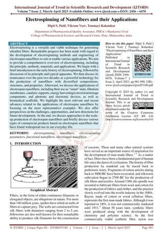
  • 1. International Journal of Trend in Scientific Research and Development (IJTSRD) Volume 7 Issue 2, March-April 2023 Available Online: www.ijtsrd.com e-ISSN: 2456 – 6470 @ IJTSRD | Unique Paper ID – IJTSRD55180 | Volume – 7 | Issue – 2 | March-April 2023 Page 981 Electrospinning of Nanofibers and their Applications Dipti S. Patil, Vikram Veer, Tanmayi Kalamkar Department of Pharmaceutical Quality Assurance, PDEA`s Shankarrao Ursal College of Pharmaceutical Sciences and Research Centre, Pune, Maharashtra, India ABSTRACT Electrospinning is a versatile and viable technique for generating ultrathin fibers. Remarkable progress has been made with regard to the development of electrospinning methods and engineering of electrospun nanofibers to suit or enable various applications. We aim to provide a comprehensive overview of electrospinning, including the principle, methods, materials, and applications. We begin with a brief introduction to the early history of electrospinning, followed by discussion of its principle and typical apparatus. We then discuss its renaissance over the past two decades as a powerful technology for the production of nanofibers with diversified compositions, structures, and properties. Afterward, we discuss the applications of electrospun nanofibers, including their use as “smart” mats, filtration membranes, catalytic supports, energy harvesting/conversion/storage components, and photonic and electronic devices, as well as biomedical scaffolds. We highlight the most relevant and recent advances related to the applications of electrospun nanofibers by focusing on the most representative examples. We also offer perspectives on the challenges, opportunities, and new directions for future development. At the end, we discuss approaches to the scale- up production of electrospun nanofibers and briefly discuss various types of commercial products based on electrospun nanofibers that have found widespread use in our everyday life. KEYWORDS: electrospinning, nanofibers, electrospinning parameters, functional nanofibers, electrospun nanofibers How to cite this paper: Dipti S. Patil | Vikram Veer | Tanmayi Kalamkar "Electrospinning of Nanofibers and their Applications" Published in International Journal of Trend in Scientific Research and Development (ijtsrd), ISSN: 2456- 6470, Volume-7 | Issue-2, April 2023, pp.981-990, URL: www.ijtsrd.com/papers/ijtsrd55180.pdf Copyright © 2023 by author (s) and International Journal of Trend in Scientific Research and Development Journal. This is an Open Access article distributed under the terms of the Creative Commons Attribution License (CC BY 4.0) (http://creativecommons.org/licenses/by/4.0) 1. INTRODUCTION Graphical Abstract Fibers, in the form of either continuous filaments or elongated objects, are ubiquitous in nature. For more than 140 million years, spiders have relied on webs of fibers to capture prey. The webs are constructed from silk fibers with diameters ranging from 2 to 5 µm. Silkworms are also well-known for their remarkable ability to produce silk filaments for the construction of cocoons. These and many other natural systems have served as an important source of inspiration for the development of man-made fibers.1–3 As a matter of fact, fibers have been a fundamental part of human life since the dawn of civilization. The historyof fiber production by mankind can be traced back to prehistoric times. Fragments of cotton articles dating back to 5000 BC have been excavated, and silkworm cultivation began in 2700 BC for the production of silk fibers and textiles. Around 1300, the spindle was invented to fabricate fibers from wool and cotton for the production of fabrics and clothes, and this practice slowly evolved into the textile industry in the 1880s. Rayon, made of cotton or wood cellulose fibers, represents the first man-made fabrics. Although it was reported in 1891, it was not commercially marketed until 1911.4 About 50 years later, synthetic fibers were produced along with the development of chemistry and polymer science. As the first commercially viable synthetic fiber, nylon was IJTSRD55180
  • 2. International Journal of Trend in Scientific Research and Development @ www.ijtsrd.com eISSN: 2456-6470 @ IJTSRD | Unique Paper ID – IJTSRD55180 | Volume – 7 | Issue – 2 | March-April 2023 Page 982 introduced by DuPont in 1938, and it immediately caught the public’s attention.5,6 Thereafter, many different types of polyesters and other synthetic polymers have been developed one after another for the manufacturing of synthetic fibers.7 The synthetic fibers significantly reduce the public’s demand for natural fibers while greatly expanding the scope of applications. Many methods have been developed for producing fibers from synthetic polymers, most notably, those based on wet, dry, melt, and gel spinning.8,9 Wet spinning involves a spinneret submerged in a chemical bath. When a polymer solution is extruded from the spinneret into the chemical bath, the polymer is precipitated out because of the dilution effect or chemical reaction, generating fibers through solidification. For dry spinning, a polymer solution is extruded into air through a spinneret and fibers are obtained as a result of solvent evaporation from the jets aided by a stream of hot air. During melt spinning, a polymer melt is extruded from a spinneret to generate fibers upon cooling. Gel spinning is used to produce fibers with high mechanical strength or other special properties by spinning a polymer in the “gel” state, followed by drying in air and then cooling in a liquid bath. During these spinning processes, jets are mainly formed under external shearing forces and/or mechanical drawing when passing through spinnerets, and fibers are formed upon solidification of the jets as a result of precipitation or drying. The jets are only stretched to a limited extent, corresponding to the formation of fibers with diameters typically in the range of 10–100 µm.8,9 Even with further mechanical drawing during the solidification process or after complete cooling of the jets, the resultant fibers still cannot reach the sub- micrometer scale. In 1887, Charles V. Boys reported that fibers could be drawn from a viscoelastic liquid in the presence of an external electric field.10 He used an apparatus consisting of an insulated dish connected to an electrical supply. It was demonstrated that a viscous liquid (e.g., beeswax and collodion) could be drawn into fibers when it moved to the edge of the dish. Widely known as electrospinning now, this technique opens the door to the production of ultrathin fibers with diameters down to the nanometer scale. In general, electrospinning allows for the facile production of continuous fibers with diameters ranging from tens of nanometers to several micrometers.11 Electrospun fibers with diameters down to 1 nm, and even below, have also been reported.12 In literature, electrospun fibers are often referred to as nanofibers when their diameters are thinner than roughly 500 nm. The concept of electrospinning was conceived in an earlier study conducted by William Gilbert in 1600, in which he observed the formation of a cone-shaped water droplet in the presence of an electric field.13 About one century later, Stephen Gray observed the electrohydrodynamic atomization of a water droplet from which a very fine stream was generated.14 In 1747, Abbé Nollet performed the earliest known electrospraying experiment, demonstrating that water could be sprayed as an aerosol when passing through an electrostatically charged vessel that was placed next to the ground.15 The behaviors of charged droplets were then systematically studied by Lord Rayleigh. In 1882, he theoretically estimated the maximum amount of charges that a liquid droplet could carry before liquid jets would be ejected from the surface.16 Electrospinning can be considered a variant of the electrospraying technique,17 both of which rely on the use of a high voltage to eject liquid jets. The major differences between electrospinning and electrospraying lie in the viscosity and viscoelasticity of the liquid involved and thus the behavior of the jet. During electrospinning, the jet can be kept in a continuous form to produce fibers instead of breaking into droplets (for the formation of particles) as with electrospraying. In 1902, two patents on electrospinning were filed by John Cooley and William Morton, respectively,18,19 describing a prototype of the setup for electrospinning. Afterward, Anton Formhals filed a couple of additional patents in 1934 and 1944 to disclose the improvement in equipment, moving toward the commercialization of electrospinning for the fabrication of textile yarns.20,21 Electrospun nanofibers were first implemented in the Soviet Union in 1938 for the development of air filters, known as “Petryanov filters”, for capturing aerosol particles. By 1939, this work had led to the establishment of a factory in Tver for the manufacturing of smoke filters with nanofiber-based mats as gas masks. During this period of time, a mechanistic understanding of electrospinning was slowly developed. Between 1964 and 1969, Geoffrey Taylor published a series of pioneering papers, showing how to mathematically describe and model the spherical to conical shape change of a polymer solution or melt droplet under the influence of a strong electric field.22–24 Specifically, as the strength of the electric field was increased beyond a critical level, the spherical droplet would gradually evolve into a cone (now commonly referred to as Taylor cone) and emanate a liquid jet. Afterward, the development of electrospinning technique experienced 20 years of stagnancy, as it did not receive much attention from academia or industry
  • 3. International Journal of Trend in Scientific Research and Development @ www.ijtsrd.com eISSN: 2456-6470 @ IJTSRD | Unique Paper ID – IJTSRD55180 | Volume – 7 | Issue – 2 | March-April 2023 Page 983 during this period of time. This stagnancy can be largely attributed to the lack of characterization tools capable of accurately measuring the sizes of fibers with diameters down to the sub-micrometer range. Nevertheless, a variety of applications were proposed for electrospun fibers during this period of time, including their potential use as wound dressing materials as described by a patent filed in 1977.25 In the early 1980s, Donaldson Co. Inc. in the U.S. began to produce and sell filters comprised of electrospun fibers for air filtration. However, the companydid not disclose the makeup of their products in order to gain advantages over its competitors. It was not until the early 1990s that several research groups, notably those led by Darrell Reneker and Gregory Rutledge, began to reinvent this technique.26– 32 This was made possible by the increased accessibility of electron microscopes capable of resolving features down to the nanometer scale. These groups demonstrated that many different organic polymers could be electrospun into nanofibers. The term “electrospinning” was popularized for describing this technique. Their studies brought new life to electrospinning, and this technique eventually became the method of choice for producing long and continuous fibers with diameters down to the nanometer scale. At the beginning of this century, electrospinning started to receive increasing attention when its capability was further expanded by switching to new materials and formulations for the fabrication of composite and ceramic nanofibers.33–35 The ability to electrospin new materials quickly enabled new applications in catalysis, as well as energy harvesting, conversion, and storage, which were traditionally dominated by inorganic nanoparticles. In parallel, new strategies were also developed to control the structure and alignment of electrospun nanofibers, opening a world of opportunities in energy-related and biomedical applications. Notably, several methods for aligning the nanofibers were developed, demonstrating the feasibility to combine different properties arising from the size, structure, composition, morphology, porosity, and assembly of nanofibers.35–38 At the same time, coaxial electrospinning was developed to produce continuous core–sheath and hollow nanofibers.39 The fabrication of continuous yarns of electro-spun nanofibers was also reported.40 brief summary of the major milestones for the development of electrospinning. These achievements make electrospinning a versatile and viable technology for the production of nanofiber-based materials to target a broad range of applications. 2. ELECTROSPINNING 2.1. Principle of Electrospinning As illustrated, the basic setup for electrospinning is rather simple, making it accessible to almost every laboratory.41,42 The major components include a high- voltage power supply, a syringe pump, a spinneret (usually, a hypodermic needle with blunt tip), and a conductive collector. The power supply can be either direct current (DC) or alternating current (AC). During electrospinning, the liquid is extruded from the spinneret to produce a pendant droplet as a result of surface tension. Upon electrification, the electrostatic repulsion among the surface charges that feature the same sign deforms the droplet into a Taylor cone, from which a charged jet is ejected. The jet initially extends in a straight line and then undergoes vigorous whipping motions because of bending instabilities. As the jet is stretched into finer diameters, it solidifies quickly, leading to the deposition of solid fiber(s) on the grounded collector. In general, the electrospinning process can be divided into four consecutive steps: (i) charging of the liquid droplet and formation of Taylor cone or cone-shaped jet; (ii) extension of the charged jet along a straight line; (iii) thinning of the jet in the presence of an electric field and growth of electrical bending instability (also known as whipping instability); and (iv) solidification and collection of the jet as solid fiber(s) on a grounded collector.41,43,44 A more detailed discussion of these four steps is provided in the following subsections.
  • 4. International Journal of Trend in Scientific Research and Development @ www.ijtsrd.com eISSN: 2456-6470 @ IJTSRD | Unique Paper ID – IJTSRD55180 | Volume – 7 | Issue – 2 | March-April 2023 Page 984 Electrospining setup Three parts make up a standard electrospinning setup: a high voltage supplier, a capillary tube containing a needle, and a collecting screen [10]. A typical electrospinning arrangement is shown in Figure 1a and b. Taylor asserts that a 6 kV applied voltage is necessary for the electrospinningprocess to begin [11]. However, the electrospinning procedurecan be carried out at a lower applied voltage when a grounded target is placed closer to the spinneret [12]. Electrospinning Parameters It is very important to understand the electrospinning working parameters, as they effect fiber morphologies. It is much easier and more possible to obtain desired fiber diameters and morphologies through control of these parameters. The ideal targets in electrospinning of a polymer into nanofiber are: A. The diameters of the fibers must be consistent and controllable B. The fiber surface must be defect-free or defect- controllable C. Continuous single nanofibers must be collectable Fiber diameter is among the most important quantities in electrospinning. Another challenge is the uniformity of the fiber diameters. The occurrence of defects such as beads and pores is a major problem the pores in Poly-L- lactide (PLLA) fibers. The beaded fiber structure can be observed in Figure 8 Solution Parameters– viscosity, conductivity, molecular weight, molecular weight distribution, surface tension, polymer structure, solution properties Process Parameters– applied electric field, tip to collector distance, feeding or flow rate, hydrostatic pressure in the capillary, plate movement Ambient Parameters– humidity and temperature of the surroundings, solution temperature, air flow rate Patterning of Nanofibers. Nanofiber-based mats with patterned micro-and/or nanostructures are interesting for their high specific surface areas and roughness. The nanofiber-based mats can be patterned using two different approaches: bottom-up and top-down. For the bottom-up approach, micropatterned architectures can be readily generated in the mats by controlling the properties of the electrospinning liquid and parameters for electrospinning. One typical example is the formation of unique ultrafine nanonets comprised of interlinked ultrathin nanowires in the as-spun nanofiber-based mat. As shown in nanonets of ultrathin nanowires (ca. 30 nm) are stacked layer- by-layer and distributed in the mat of poly (acrylic acid) nanofibers. The nanonets are only formed under certain conditions, for example, electrospinning of a solution containing salts or involvement of fast phase separation between the polymer and solvent. Electrospinning under a relatively high voltage or low relative humidity may also result in the formation of nanonets. In another typical example, PVA nanofiber- based mat with a honeycomb-patterned architecture was fabricated by inducing the self-assembly of wet nanofibers on a collector Micropatterned architectures can also be readily generated through the use of micropatterned conductive templates as collectors, as discussed in . In this case, the electrical forces are the key factors in determining both the deposition and arrangement of nanofibers. The melt and near-field electrospinning techniques have also been demonstrated for patterning fibers through direct writing as discussed is and respectively. The drawbacks are the complicated setups and relatively large feature sizes. Classification of electrospinning methods depending upon design of electrospinning setup. Emulsion electrospinning. This method provides us a chance to make a single fibrous scaffold out of two immiscible solutions when they are electrospun, the method specifies that the immiscible solutions are to be made into an emulsion by mixing strenuously after which the resulting colloid is packed into a syringe made out of glass and fitted with a power supply of high voltage and a needle. Fibers which are made out of this are difficult to produce as it involves a plethora of variables that are to be accounted for to create the emulsion. Nanoparticles and surfactants like sod. Dodecyl sulfate has been used for interface stabilization effectively.42 In this method, the core–shell containing functional materials like peptides, proteins, enzymes, and flavonoids are incorporated into a nanofiber. The setup of emulsion electrospinning is shown in. As far as emulsion material passes through the needle, due to the potential difference between the needle and collector plate results in the formation of nanofiber containing core–shells of emulsion droplets. The attenuation and deformation of this emulsion droplet occurred as a result of jet speed which drags the forces derived from its interaction with the surrounding air. Due to this, the solvent gets evaporated quickly and nanofiber with a core–shell containing fundamental material is formed.42
  • 5. International Journal of Trend in Scientific Research and Development @ www.ijtsrd.com eISSN: 2456-6470 @ IJTSRD | Unique Paper ID – IJTSRD55180 | Volume – 7 | Issue – 2 | March-April 2023 Page 985 Fig. 5 Pictorial representation of setup used for fabrication of nanofibers by (a) emulsion electrospinning, (b) coaxial electrospinning, (c) roller electrospinning, (d) melt electrospinning, (e) magnetic-field facilitated electrospinning with two parallel permanent magnets, (f) bicomponent electrospinning, (g) force spinning, (h) charge injection method and (i) near-field electrospinning. Coaxial electrospinning. A technique that can be used to make core–shell (core–sheath) fibers by using spinneret in which there are two compartments (coaxial), where the shell/sheath (solution of polymer) and core (a solution of a compound) can be used as the precursors and co- spun, core–shell (2 different polymer solution can also be used). The fluids are independently driven using two compartments simultaneously in this method; the outer and inner solutions (precursors) reach the nozzle by passing from their capillaries and combining to produce droplets of composite. As both the solutions extrude through the jet, a nanofiber yarn is formed in which the core is surrounded by shell/sheath material as shown in . Most of the time shell is acts as a physical barrier to avoid the evaporation of core material.43 Because of the electrostatic repulsive forces present in the middle of the surface, the extension was seen in the shell liquid of composite droplets, resulting in viscid tension then the resulting tension was transmitted to the core layer, which was quickly stretched.44, 45 Melt-blowing setup It is a setup of single-step to produce materials on a micrometer and small scale. Once the polymer was melted, multiple nozzles are used to eject the jet of polymer simultaneously. After that, jets were enervated using the hot air stream (high velocity), resulting in a drastic decrease in the diameter of jets. Ultimately, a web of fibers that are fine, have a random position and are non-woven gets deposited on the collector.46 Gas-assisted spinning Also known as the spin blowing method gives a useful way to spin material that is considered poor
  • 6. International Journal of Trend in Scientific Research and Development @ www.ijtsrd.com eISSN: 2456-6470 @ IJTSRD | Unique Paper ID – IJTSRD55180 | Volume – 7 | Issue – 2 | March-April 2023 Page 986 material for electrospinning.47 Reyhaneh Aminyan et al. prepared fibers of 11% wt of aqueous a solution. The prepared fibers were kept under 20 kV voltage, followed by neutralization by 15 wt% NaOH solution, 20 rpm of the rotation speed of the collector with the fed rate of 20 µl min−1 (chosen conditions were rationalized by the previous group's experiences). Then they crosslinked prepared fibers using 1,4- butanediol diglyceryl ether at 0.5, 0.4, and 0.3% wt for 3–7 min at the temperature of 130–1600 °C. The prepared cross-linked specimens were used to obtain results by conducting the swelling ratio analysis.48 Low fiber productivity is the primary problem associated with the typical electrospinning procedure. To bettering the productivity of fibers by introducing the gas jet with the application of increased driving force around the solution of the polymer. Integrated fibers with a narrower diameter dispersity can be achieved using gas-assisted electrospinning.48 Roller electrospinning (nano spider electrospinning).This particular device consists of a tank, a ground collector, a supporting material, and a power supply of high voltage.49 in this, to spin nanofibers a spinning roller electrode is half dipped into the polymer solution. An electrode (grounded) with non-woven material is fixed on the peak of the spine which makes a continuous nanofibers Self-bundling electrospinning Self-bundling electrospinning is rather a straightforward mechanism for creating continuously aligned electrospun fiber yarn. It has manythings like a needle tip, a syringe pump, a generator (high- voltage), and a ground collector (rotating).51 To start the formation of a bundle, a ground tip that is twisted around the collector is used and then the bundling continues. The solution's conductivity (electrical) is contemplated to be a criterion of a significant impact.52 Solvent-free electrospinning Solvent-free electrospinning such as melt electrospinning, CO2-assisted electrospinning, and anion-curing electrospinning are techniques and never use conventional solvents. It is used to highly utilize precursors and avoid solvent emission.53 A. Melt electrospinning The setup consists of a cylindrical collector, molten polymer, a needle, and a high-voltage power supply. For melting the polymer different techniques can be used such as electric heating, laser melting devices, heat guns, and heating ovens. Generally, the parameters are the same for molten polymer electrospinning as it is for the polymer solution electrospinning. Just like the latter, a large diameter is taken using a polymer with higher molecular wt and in the maximum cases, the melted one also has both nano and micrometer-scale fibers but there are some differences as well. The method for fabrication of nanofibers by electrospinning setup is illustrated in In melt electrospinning, before initiating an uninterrupted heat supply to the reservoir, it had to be made sure that the solution of polymer is in the molten state. The gap between the tip and collector is roughly around 2 cm in melt electrospinning whereas it's around 10 cm in the conventional polymer solution electrospinning. A greater charge is required to start the jets in melt electrospinning because the viscosity of polymer melt is higher in the molten electrospinning when compared to the conventional polymer solution electrospinning.54 B. UV-curing electrospinning UV-curing electrospinning method is used to develop fibers that are ultrathin nanofibres, modifications have to be done for creating an oxygen-free environment. Then only the precursors can be electrospun with the ultra-violet radiation and within the nitrogen then problems like solvent evaporation are not faced and fibers can be made ultrathin. The method utilizes an ultra-violet mendable material. An oxygen-free environment is created so that the precursors can be electro-spun under UV light and nitrogen into ultrathin fibers.53,55 C. Anion-curing electrospinning Only two components are there in the solution, the cyanoacrylate (ca.) monomer and polymethyl methacrylate (PMMA). The latter is added to the former to increase the viscosity. Room temperature is enough for more than 90% of the precursor to be electrospun into ultrathin fibers. The acrylic resin (ca. monomer) may polymerize quickly and create strong chains in the presence of an anion. Just as the room temperature has a compelling impact on the diameter of the electrospun fibers created by the traditional method, it also affects the morphology of the anion- cured electro-spun fibers.47 D. Supercritical CO2-assisted electrospinning In this method, electrostatic forces and supercritical CO2 solvents were used to make the polymer fibers. Carbon dioxide is the most commonly found supercritical solvent used in many processes and is known as a material that possesses both the temperature and pressure above the critical point because the supercritical stage is performed in a vessel with high pressure (14 mPa). So, it's difficult to employ a moving collector. The apparatus for this approach is far more sophisticated than any other method.53
  • 7. International Journal of Trend in Scientific Research and Development @ www.ijtsrd.com eISSN: 2456-6470 @ IJTSRD | Unique Paper ID – IJTSRD55180 | Volume – 7 | Issue – 2 | March-April 2023 Page 987 Magnetic-field-assisted electrospinning Fibers made using this technique don't split much like the ones without a magnetic field and are much more uniform. The advantage of the fibers which are made from this method is that they are more uniform and are with much less splitting than others. In this method, either 2 parallel permanent magnets should be used or Helmholtz coils, plus a syringe that contains the solutions that are compatible and can respond to magnets that are used. With this method, fibers with smaller diameters were attained because of high speed.56 Below the setup of two parallel magnets with magnetic field-assisted electrospinning. Bicomponent spinning This technique can be used to make mono and multi- component nanofibers. It's a 2-step process that involves producing nanofibers by splitting or removing one of the components when 2 polymers are spun through a spinning die. For us to produce a nanofiber there should be at least one component that has a cross-section in the nanoscale. Some of the common shapes for the bi-component fibers are segmented pie (hollow, ribbon, plain), sheath–core, side by side, etc. If shapes are to be explained, for instance, islands in the sea in which the sea is of one polymer need to be enclosed by other polymers known as islands (multiple individual fibrils) as shown in the.57 Force spinning (centrifugal spinning) This particular method is known to be well refined and is also called rotational/rotary spinning. The only dissemblance between the said method and the original one is the use of c-force in place of the electric field. In this method when the speed of rotation reaches a certain point then the c-force will be significant enough to subdue the surface tension then only the liquid jet will be excluded from the tip. Ultimately, the c-force will make the jet stretched and nanofibers will be deposited on the collector. The most significant drawback of centrifugal spinning is that material characteristics and spinneret design have a significant impact on fiber quality and production. Charge injection method This technique was refined for electro-spraying still it can be used for electrospinning. This method is dissimilar from the ones used by other devices. This method doesn't involve the formation of Taylor cones and the splitting of the jet is done by an electrical charge. Out of many configurations for this technique, one of them involves three electrodes (power supply-high voltage, collector, and non- conducting pressurized fluid) and two out of those are submerged into the solution The “emitter electrode's” sharpened tip is situated above a grounded orifice i.e. blunt electrode. A strong e-field is created in the solution due to the narrow proximity between electrodes. As the fluid travels between the electrodes, it is continually pushed through the aperture at increased pressure and becomes highly charged, the extruded filaments from the orifice might be drawn towards the collector. Because of the proximity of the emitter electrode and aperture, this method has some certain disadvantages, like the lack of control over the size distribution of the fibers and that only fluids which have low conductivity/insulating can be used. As a matter of fact, the electro-spun mats are normally made of microfibers which are interconnected branches of nanoscale fibers.60 NFES (near-field electrospinning) Apart from the distance between the needle and the collector the system setup is the same as standard. The reduction in the distance (500 µm to 3 mm) is to avert the curving unsteadiness of the jet. The distance in the question employs a sturdy area of the electro- spun jet near the needle, which makes this system good for direct writing. But this closeness between the collector and the spinneret may create electric breakdown or splattering of the fibers because of insufficient evaporation of the solvent. As a result, an adjustment must be done with the polymer solution accurately. To initiate the process, a lower applied voltage (usually 100–600 V) is utilized. In contrast to traditional electrospinning, higher voltage has been observed to result in bigger diameter fibers in this method. With the volume of the collected fibers being limited, the alone droplet of the polymer is more than enough for the direct writing, negating the necessity for a consistent flow of polymer. To get an accurate control over orientation and deposition of the fibers the collector is normally put up on the XY-piezo stage.61 The setup of near-field electrospinning setup was well illustrated in CONCLUSION Over the past two decades or so, remarkable progress has been made with regard to the development of electrospinning methods and engineering of electrospun nanofibers to suit or enable various applications. Most of the advances were made possible through the achievement of a better understanding of the electrospinning mechanism and a better control of the materials. A wide variety of materials, including polymers, small molecules, and colloidal particles, as well as composites, have been successfully electrospun into nanofibers. In terms of methods, electrospinning has been performed in both far-and near-field configurations. The spinneret has been designed with a hollow, solid, or coaxial
  • 8. International Journal of Trend in Scientific Research and Development @ www.ijtsrd.com eISSN: 2456-6470 @ IJTSRD | Unique Paper ID – IJTSRD55180 | Volume – 7 | Issue – 2 | March-April 2023 Page 988 structure and utilized as a single unit or in an array. In addition to conductive solid collectors with different surface patterns, liquid bath has been explored as a collector to enable the fabrication of nanofibers with novel structures and morphologies, in addition to the extension of dimensionality. During or post- electrospinning, it is also feasible to expand the diversity, scope, and functionality of electrospun nanofibers by engineering their composition, structure, morphology, and assembly. Notable examples include the fabrication of nanofibers made of carbon, ceramics, or metals; incorporation of enzymes, biological effectors, or nanoparticles into nanofibers; creation of pores and/or hollow interiors in the nanofibers; conjugation of specific functional groups or biological effectors to the surface of nanofibers; alignment of nanofibers into uniaxial or radial arrays; stacking of nanofibers into patterned architectures; and fabrication of 3D scaffolds by expanding a thin mat of nanofibers along the vertical direction. As a result of their remarkable properties, electrospun nanofibers have found widespread use in a variety of applications ranging from catalysis to environmental protection, energy harvesting/conversion/storage, and biomedicine. Specifically, owing to their high porosity and large specific surface areas, nonwoven mats of electrospun nanofibers have been applied as advanced filters for the removal of pollutants from both polluted air and wastewater. Upon optimization in terms of diameter, porosity, alignment, stacking, surface functional groups, mechanical properties, and biodegradability, nanofiber-based scaffolds have been explored to enhance the repair or regeneration of various types of tissues, including nerve, skin, heart, blood vessel, musculoskeletal system, and tissue interfaces. Recent clinical trials on electrospun nanofibers have begun to pave the way for their ultimate implementation in regenerative medicine, especially for use as barrier membranes to prevent the adhesion between tissues after surgery. ACKNOWLEDGMENTS The authors would like to acknowledge PDEA`s Shankarrao Ursal College of Pharmaceutical Sciences and Research Centre, Pune, Maharashtra, India for offering all vital help to accomplish this work efficaciously CONFLICT OF INTEREST: All authors declared no conflict of interest for the work. REFERENCES [1] Vollrath F; Knight DP Liquid Crystalline Spinning of Spider Silk. Nature 2001, 410, 541–548. [2] Heim M; Keerl D; Scheibel T Spider Silk: From Soluble Protein to Extraordinary Fiber. Angew. Chem., Int. Ed 2009, 48, 3584–3596 [3] Andersson M; Jia Q; Abella A; Lee X-Y; Landreh M; Purhonen P; Hebert H; Tenje M; Robinson CV; Meng Q; et al. Biomimetic Spinning of Artificial Spider Silk from a Chimeric Minispidroin. Nat. Chem. Biol 2017, 13, 262– [4] Woodings C, Ed. Regenerated Cellulose Fibres; Woodhead: Cambridge, U.K., 2001; Chapter 5. [5] Carothers WH Alkylene Ester of Polybasic Acids U.S. Pat. 2,012,267, 1935. [6] Carothers WH Linear Condensation Polymers U.S. Pat. 2,071,250, 1937. [7] McIntyre JE Synthetic Fibres: Nylon, Polyester, Acrylic, Polyolefin; Woodhead: Cambridge, U.K., 2005; Chapter 1. [8] Gupta V, Kothari V, Eds. Manufactured Fibre Technology; Chapman & Hall: London, 1997; Chapter 1. [9] Luo C; Stoyanov SD; Stride E; Pelan E; Edirisinghe M Electrospinning Versus Fibre Production Methods: From Specifics to Technological Convergence. Chem. Soc. Rev 2012, 41, 4708–4735 [10] Boys CV On the Production, Properties, and Some Suggested Uses of the Finest Threads. Proc. Phys. Soc. London 1887, 9, 82013 [11] Dzenis Y Spinning Continuous Fibers for Nanotechnology. Science 2004, 304, 1917– 1919. [12] Jian S; Zhu J; Jiang S; Chen S; Fang H; Song Y; Duan G; Zhang Y; Hou H Nanofibers with Diameter Below One Nanometer from Electrospinning. RSC Adv 2018, 8, 4794–4802. [13] Gilbert W De Magnete; Courier: New York, 1958. [14] Gray SA Letter Concerning the Electricity of Water, from Mr. Stephen Gray to Cromwell Mortimer. Philos. Trans. R. Soc. London 1731, 37, 227–260. [15] Nollet JAX Part of a Letter from Abbè Nollet, of the Royal Academy of Sciences at Paris, to Martin Folkes, Concerning Electricity. Philos. Trans 1748, 45, 187–194. [16] Rayleigh L XX. On the Equilibrium of Liquid Conducting Masses Charged with Electricity. Philos. Mag 1882, 14, 184–186.
  • 9. International Journal of Trend in Scientific Research and Development @ www.ijtsrd.com eISSN: 2456-6470 @ IJTSRD | Unique Paper ID – IJTSRD55180 | Volume – 7 | Issue – 2 | March-April 2023 Page 989 [17] Bailey AG Electrostatic Spraying of Liquids; John Wiley & Sons: New York, 1988. [18] Cooley JF Apparatus for Electrically Dispersing Fluids U.S. Pat. 692,631, 1902. [19] Morton WJ Method of Dispersing Fluid U.S. Pat. 705,691, 1902. [20] Formhals A Process and Apparatus for Preparing Artificial Threads U.S. Pat. 1,975,504, 1934. [21] Formhals A Method and Apparatus for Spinning U.S. Pat. 2,349,950, 1944. [22] Taylor GI Disintegration of Water Drops in an Electric Field. Proc. R. Soc. London A 1964, 280, 383–397. [23] Taylor GI The Force Exerted by an Electric Field on a Long Cylindrical Conductor. Proc. R. Soc. London, Ser. A 1966, 291, 145–158 [24] Taylor G Electrically Driven Jets. Proc. R. Soc. London, Ser. A 1969, 313, 453–475. [25] Martin GE; Cockshott ID Fibrillar Lining for Prosthetic Device U.S. Pat. 4,044,404, 1977. [26] Fong H; Chun I; Reneker DH Beaded Nanofibers Formed During Electrospinning. Polymer 1999, 40, 4585–4592. [27] Reneker DH; Yarin AL; Fong H; Koombhongse S Bending Instability of Electrically Charged Liquid Jets of Polymer Solutions in Electrospinning. J. Appl. Phys 2000, 87, 4531–4547. [28] Shin YM; Hohman MM; Brenner MP; Rutledge GC Experimental Characterization of Electrospinning: The Electrically Forced Jet and Instabilities. Polymer 2001, 42, 09955– 09967. [29] Yarin AL; Koombhongse S; Reneker DH Bending Instability in Electrospinning of Nanofibers. J. Appl. Phys 2001, 89, 3018–3026. [30] Hohman MM; Shin M; Rutledge GC; Brenner MP Electrospinning and Electrically Forced Jets. I. Stability Theory. Phys. Fluids 2001, 13, 2201–2220. [31] Hohman MM; Shin M; Rutledge GC; Brenner MP Electrospinning and Electrically Forced Jets. II. Applications. Phys. Fluids 2001, 13, 2221–2236. [32] Shin YM; Hohman MM; Brenner MP; Rutledge GC Electrospinning: A Whipping Fluid Jet Generates Submicron Polymer Fibers. Appl. Phys. Lett 2001, 78, 1149–1151. [33] Dai H; Gong J; Kim H; Lee D A Novel Method for Preparing Ultra−Fine Alumina−Borate Oxide Fibres via an Electrospinning Technique. Nanotechnol 2002, 13, 674–677. [34] Larsen G; Velarde-Ortiz R; Minchow K; Barrero A; Loscertales IG A Method for Making Inorganic and Hybrid (Organic/Inorganic) Fibers and Vesicles with Diameters in the Submicrometer and Micrometer Range via Sol−Gel Chemistry and Electrically Forced Liquid Jets. J. Am. Chem. Soc 2003, 125, 1154–1155. [35] Li D; Wang Y; Xia Y Electrospinning of Polymeric and Ceramic Nanofibers as Uniaxially Aligned Arrays. Nano Lett 2003, 3, 1167–1171. [36] Theron A; Zussman E; Yarin A Electrostatic Field−Assisted Alignment of Electrospun Nanofibres. Nanotechnology 2001, 12, 384– 390. [37] Deitzel JM; Kleinmeyer JD; Hirvonen JK; Beck Tan NC Controlled Deposition of Electrospun Poly(ethylene oxide) Fibers. Polymer 2001, 42, 8163–8170. [38] Dersch R; Liu T; Schaper A; Greiner A; Wendorff J Electrospun Nanofibers: Internal Structure and Intrinsic Orientation. J. Polym. Sci., Part A: Polym. Chem 2003, 41, 545–553. [39] Sun Z; Zussman E; Yarin AL; Wendorff JH; Greiner A Compound Core−Shell Polymer Nanofibers by Co-Electrospinning. Adv. Mater 2003, 15, 1929–1932. [40] Smit E; Bűttner U; Sanderson RD Continuous Yarns from Electrospun Fibers. Polymer 2005, 46, 2419–2423. [41] Li D; Xia Y Electrospinning of Nanofibers: Reinventing the Wheel? Adv. Mater 2004, 16, 1151–1170. [42] Xue J; Xie J; Liu W; Xia Y Electrospun Nanofibers: New Concepts, Materials, and Applications. Acc. Chem. Res 2017, 50, 1976–1 [43] Sun B; Long YZ; Zhang HD; Li MM; Duvail JL; Jiang XY; Yin HL Advances in Three- Dimensional Nanofibrous Macrostructures via Electrospinning. Prog. Polym. Sci 2014, 39, 862–890. [44] Liao Y; Loh CH; Tian M; Wang R; Fane AG Progress in Electrospun Polymeric Nanofibrous Membranes for Water Treatment: Fabrication, Modification and Applications. Prog. Polym. Sci 2018, 77, 69–94.
  • 10. International Journal of Trend in Scientific Research and Development @ www.ijtsrd.com eISSN: 2456-6470 @ IJTSRD | Unique Paper ID – IJTSRD55180 | Volume – 7 | Issue – 2 | March-April 2023 Page 990 [45] Duft D; Achtzehn T; Müller R; Huber BA; Leisner T Rayleigh Jets from Levitated Microdroplets. Nature 2003, 421, 128. [46] Li D; Marquez M; Xia Y Capturing Electrified Nanodroplets under Rayleigh Instability by Coupling Electrospray with a Sol−Gel Reaction. Chem. Phys. Lett 2007, 445, 271– 275. [47] Reneker DH, Fong H, Eds. Polymeric Nanofibers; American Chemical Society: Washington, DC, USA, 2006; DOI: 10.1021/bk-2006-0918. [48] Finn R Capillary Surface Interfaces. Notices AMS 1999, 46, 770–781. [49] Young T III. An Essay on the Cohesion of Fluids. Philos. Trans. R. Soc. London 1805, 95, 65–87. [50] Reneker DH; Yarin AL Electrospinning Jets and Polymer Nanofibers. Polymer 2008, 49, 2387–2425. [51] Yarin AL; Koombhongse S; Reneker DH Taylor Cone and Jetting from Liquid Droplets in Electrospinning of Nanofibers. J. Appl. Phys 2001, 90, 4836–4846. [52] Collins RT; Jones JJ; Harris MT; Basaran OA Electrohydrodynamic Tip Streaming and Emission of Charged Drops from Liquid Cones. Nat. Phys 2008, 4, 149–154. [53] Fridrikh SV; Yu JH; Brenner MP; Rutledge GC Controlling the Fiber Diameter During Electrospinning. Phys. Rev. Lett 2003, 90, 144502. [ [54] Feng J The Stretching of an Electrified Non−Newtonian Jet: A Model for Electrospinning. Phys. Fluids 2002, 14, 3912– 3926. [55] Feng J Stretching of a Straight Electrically Charged Viscoelastic Jet. J. Non-Newtonian Fluid Mech 2003, 116, 55–70. [56] He JH; Wu Y; Zuo WW Critical Length of Straight Jet in Electrospinning. Polymer 2005, 46, 12637–12640. [57] Reneker DH; Kataphinan W; Theron A; Zussman E; Yarin AL Nanofiber Garlands of Polycaprolactone by Electrospinning. Polymer 2002, 43, 6785–6794. [58] Helgeson ME; Grammatikos KN; Deitzel JM; Wagner NJ Theory and Kinematic Measurements of the Mechanics of Stable Electrospun Polymer Jets. Polymer 2008, 49, 2924–2936. [59] Gañán-Calvo AM Cone−Jet Analytical Extension of Taylor’s Electrostatic Solution and the Asymptotic Universal Scaling Laws in Electrospraying. Phys. Rev. Lett 1997, 79, 217– 220. [60] Xu H Formation and Characterization of Polymer Jets in Electrospinning Ph.D. Thesis; University of Akron, Akron, OH, USA, 2003.