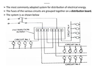
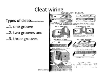
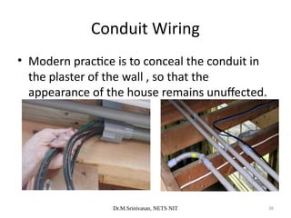
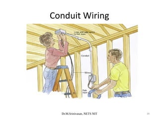
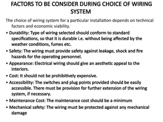
MODULE - 2 18EE822
ELECTRICAL ESTIMATION AND COSTING (PROFESSIONAL
ELECTIVE)
Module-2
Wiring: Introduction, Distribution of energy in a Building, PVC Casing
and Capping, Conduit Wiring, Desirabilities of Wiring. Types of cables
used in Internal Wiring, Multi Strand Cables, Voltage Grading and
Specification of Cables.
Wiring (continued): Main Switch and Distribution Board, Conduits and
its accessories and Fittings. Lighting Accessories and Fittings, Types of
Fuses, Size of Fuse, Fuse Units, Earthing Conductor.
Internal Wiring: General rules for wiring, Design of Lighting Points (Refer
to Seventh Chapter of the Text Book), Number of Points, Determination
of Total Load, Number of Sub –Circuits, Ratings Main Switch and
Distribution Board and Size of Conductor. Current Density, Layout.
Introduction
Introduction
➢ The network of wires connecting various accessories for
distribution of electrical energy from supplier meter board to
the numerous electrical devices is known as Wiring.
➢ The supplier service cable feeding an installation terminates
called Service Cutout.
➢ The point at which the consumers wiring are connected into
the cutout is known as
consumer’s terminals.
➢ From the consumer terminals onwards the supply cables are
entirely under the control of consumer and laid out as per the
selection.
➢ The typical house wiring is as shown.
Systems of Distribution of Electrical Energy
As per the recommendation of Indian standards the
maximum number of points of lights and fans that
can be connected in one circuit is 10 and the
maximum load that can be connected in such a
circuit is 800 Watts, in case more load or points are
required to be connected to the supply, then it is to
be done by having more than one circuit to
distribute supply.
There are 2 types of Distribution systems.
Distribution Board System
➢
➢ Tree System
Distribution Board System
➢ The most commonly adopted system for distribution of electrical energy.
➢ The fuses of the various circuits are grouped together on a distribution board.
➢ The system is as shown below
➢ The two copper strips, known as Bus bars fixed in
the distribution board of hard wood or metal case
are connected to the supply mains through the
linked switch.
➢ So that the installation can be switched off as a
whole from both the poles of the supply if required.
➢ A fuse is inserted in the phase wire of each circuit
so that each circuit is connected through its own
fuse.
➢ The no of circuits and sub circuits is decided as per
no of points to wired and load to be connected to a
supply system.
Tree System
➢ In this system the smaller branches are taken from
the main branch, as shown in fig, the wiring
resembles a tree
➢ As the branch is taken off, a fuse is inserted.
➢ This system used to be employed in early
days.
➢ This system has following drawbacks • The
voltage across all the lamps does not remain
the same.
• The no of joints are involved in every circuit.
• Fuses are scattered.
• In occurrence of fault all the joints are required
to be open for testing purpose.
Electrical Wiring Systems
Dr.M.Srinivasan, NETS NIT 10
1. life of installation
2. future extension or alterations
3. construction of building
4. fire hazards or other special conditions
5. corrosive fumes
6. dampness
7. type of wire and material used
8. nature of load (lighting of power)
9. safety of the system
10. cost of wiring system
Points to be considered while selecting any
system of wiring
Dr.M.Srinivasan, NETS NIT 11
1. single-phase two-wire system
2. three-phase three-wire system
3. three-phase four-wire system
Various systems by which power is
distributed to the domestic consumers
Dr.M.Srinivasan, NETS NIT 12
Commonly used types of wiring systems for
residential buildings ,commercial buildings etc.
1. Cleat wiring
2. Wooden casing and capping wiring
3. C. T. S or T. R. S. wiring
4.Metal Sheathed or Lead Sheathed wiring
5. Conduit wiring
Types of wiring
Dr.M.Srinivasan, NETS NIT 13
Cleat wiring
Dr.M.Srinivasan, NETS NIT 14
• Cleat wiring is normally used for temporary
wiring purpose.
• Ex..functions, marriages…etc.
• In this type of wiring vulcanized india
rubber(V.I.R) or polyvinyl chloride(PVC)
insulated wires are used as conductors.
• Wires are held by the help of porcelain cleat
which are placed 6mm off the walls or ceilings.
Cleat wiring
Dr.M.Srinivasan, NETS NIT 15
• As shown in dia. Grooves are provided in the
base portion of the cleat for accommodating
the wires.
• wiring is done as shown in figure..
Cleat wiring
Dr.M.Srinivasan, NETS NIT 16
Types of cleats…………
…1. one groove
…2. two grooves and
…3. three grooves
Cleat wiring
Dr.M.Srinivasan, NETS NIT 17
Advantages
1. cheapest system of internal wiring
2. installation and dismantlement is easy and
quick
3. material is recoverable after the dismantlement
4. inspection, alternations and additions can be
easily made
5. skill required is little
Cleat wiring
Dr.M.Srinivasan, NETS NIT 18
Disadvantages
1. it is not looking good
2. quit temporary and perishes quickly
3. wire are exposed to mechanical injury
4. oil and smoke are injurious to V.I.R insulation
5. not suitable for domestic premises.
Cleat wiring
Dr.M.Srinivasan, NETS NIT 19
Field of application
1. the wiring of this type is suitable for
temporary installations in dry places.
2. this is also accepted where appearance is not
so important and cheapness is the main
consideration
Cleat wiring
Dr.M.Srinivasan, NETS NIT 20
• This is one of the cheapest type of wiring and is
commonly used for house wiring.
• The cable used in this type of wiring is either
V.I.R or P.V.C or any approved insulated cables.
• Casing consist of V-shaped grooves and is
covered by rectangular strip of teak wood known
as capping.
• This type of wiring adopted up to 250 V in dry
places and in places where no risk of fire.
Wooden Casing and Capping Wiring
Dr.M.Srinivasan, NETS NIT 21
Wooden Casing and Capping Wiring
Dr.M.Srinivasan, NETS NIT 22
Wooden Casing and Capping Wiring
Dr.M.Srinivasan, NETS NIT 23
Advantages
1. better appearance than cleat wiring
2. cheap in cost
3. easy to install and rewire
4. easy to inspect by opening the capping
Wooden Casing and Capping Wiring
Dr.M.Srinivasan, NETS NIT 24
Disadvantages
1. not suitable in damp places
2. risk of fire
3. this type of wiring can only be used on surface
and can not be concealed in plaster.
4.Since it requires better workmanship , labour
cost is more
Wooden Casing and Capping Wiring
Dr.M.Srinivasan, NETS NIT 25
• Field of application
• This type of wiring is suitable for low voltage
domestic installations in dry places and where
there is no risk of fire hazards
Wooden Casing and Capping Wiring
Dr.M.Srinivasan, NETS NIT 26
• This type of wiring is also used for house
wiring and is quite cheap.
• Cab tyre sheathed (C.T.S) wire or tough rubber
sheathed (T.R.S) wire is normally used as
conductor for this wiring.
C.T.S or T.R.S Wiring
Dr.M.Srinivasan, NETS NIT 27
• The wires are run on the teak wooden battens
which are fixed on the wall or the ceiling by
means of screws and wooden plugs.
• C.T.S OR T.R.S cables used are not much
affected by chemicals , water, and steam.
C.T.S or T.R.S Wiring
Dr.M.Srinivasan, NETS NIT 28
Advantages
1. it is easy to install and repair
2. it gives better appearance
3. its life is long
4. it is fire proof up to a certain limit
5. it is cheaper than other types of wiring except cleat
wiring
6. conductors have strong insulations
7. chemicals do not affect the conductor insulation
C.T.S or T.R.S Wiring
Dr.M.Srinivasan, NETS NIT 29
• Disadvantages
• 1. the conductors are open and liable to
mechanical injury thus this type of wiring
cannot be used in workshops etc.
• 2. its use in places open to sun and rain is
restricted
• 3. good workmanship is suitable where acids
and alkalis to be prescut.
C.T.S or T.R.S Wiring
Dr.M.Srinivasan, NETS NIT 30
• This type of wiring is adopted for low voltage
installation.
• This system is similar to C.T.S wiring except that
the cable used is different in this wiring system.
• In this type of system conductors are insulated
with V.I.R and then covered with an outer
sheath of lead aluminium alloy containing 95%
lead and 5% aluminium.
Metal Sheathed Wiring
Dr.M.Srinivasan, NETS NIT 31
• The metal sheath is provided over the insulated conductor
in order to protect system from mechanical injury ,
dampness, and atmospheric action.
• Same as C.T.S wiring system cables are run on wooden
batten and are fixed with the help of tinned link clips.
Metal Sheathed Wiring
Dr.M.Srinivasan, NETS NIT 32
Metal Sheathed Wiring
Dr.M.Srinivasan, NETS NIT 33
Advantages
1. conductors are protected against mechanical
injury
2. it is suitable employed under damp situations
3.it gives better appearance
4.it has longer life
5. conductors are protected against chemicals
6. it can be installed in open space
Metal Sheathed Wiring
Dr.M.Srinivasan, NETS NIT 34
Disadvantages
1. cables are costlier than C.T.S OR T.R.S wires
2. In case of leakage ,there is risk of shock
3. skilled labour and proper supervision is
required
4. it is not suitable for places where chemical
corrosion may occur
Metal Sheathed Wiring
Dr.M.Srinivasan, NETS NIT 35
• Field of application
• This wiring system is suitable for low voltage (up to
250V) installations.
• It may be used in places exposed to sun and rain
provided no joint is exposed.
• It may be used in damp placed with a suitable
protective covering.
• This type of wiring is very common in use these days
except for some small installations and distribution
boards etc.
Metal Sheathed Wiring
Dr.M.Srinivasan, NETS NIT 36
Conduit Wiring
Dr.M.Srinivasan, NETS NIT 37
• Conduit wiring system is best for domestic and
commercial installations.
• It provide proper protection to the installation against
fire hazards, shock, mechanical damage and dampness.
• The cable used in this system is either V.I.R or P.V.C
insulated and is run in mild steel or P.V.C pipes called
conduits.
• Conduits carrying the insulated wires can be installed
on the surface of the walls or concealed in the walls
and the ceiling.
Conduit Wiring
Dr.M.Srinivasan, NETS NIT 38
• Modern practice is to conceal the conduit in
the plaster of the wall , so that the
appearance of the house remains unuffected.
Conduit Wiring
Dr.M.Srinivasan, NETS NIT 39
Conduit Wiring
Dr.M.Srinivasan, NETS NIT 40
Advantages
1. conduit provides protection against
mechanical injury and fire & is shock proof
2. conduit provides protection against chemicals
3. the whole system is water proof
4. conductors are safety secured from moisture
5. this wiring has far better look
6. it has a longer life
Conduit Wiring
Dr.M.Srinivasan, NETS NIT 41
• Disadvantages
• 1. it is costly system of wiring
• 2. it requires more time for erection
• 3. it requires highly skilled labour
• 4. internal condensation of moisture may
cause damage to the insulation unless the
system outlets are drained and ventilated
Conduit Wiring
Dr.M.Srinivasan, NETS NIT 42
Field of application
1. Places where considerable dust of puff is present such as
textile mills, saw mills, flour mills etc.
2. Damp situations
3. In workshops for lighting and motor wiring
4. Places where there is possibility of fire hazards such as in oil
mills, varnish factories, etc.
5.Placed where important documents are kept such as record
room
6.Residential and public buildings where the appearance is of
prime importance
Conduit Wiring
FACTORS TO BE CONSIDER DURING CHOICE OF WIRING
SYSTEM
The choice of wiring system for a particular installation depends on technical
factors and economic viability.
• Durability: Type of wiring selected should conform to standard
specifications, so that it is durable i.e. without being affected by the
weather conditions, fumes etc.
• Safety: The wiring must provide safety against leakage, shock and fire
hazards for the operating personnel.
• Appearance: Electrical wiring should give an aesthetic appeal to the
interiors.
• Cost: It should not be prohibitively expensive.
• Accessibility: The switches and plug points provided should be easily
accessible. There must be provision for further extension of the wiring
system, if necessary.
• Maintenance Cost: The maintenance cost should be a minimum
• Mechanical safety: The wiring must be protected against any mechanical
damage
WIRE AND CABLE
The single wire may be bare or covered with
insulation, is known as wire. The several wires
stranded together called cable.
The cable consists of three parts:
• A conductor or core; the metal wire or strand of
wires carrying current.
• The Insulation: A covering of insulation material
to avoid leakage of current from the conductors
• The protective layer for protection of insulation
from mechanical damage.
Conductor materials used in a cable
The function of the conductor usually known as a core, in a cable is to
carry electrical current.
1. Copper: The copper is the cheaper and best conductor available the
electrical conductivity is comparatively high. It is mechanical strong,
hard, extremely tough, durable and ductile. It is highly resistive to
corrosion. It can withstand the dampness and high temperature. The
copper conductors may be annealed or hard drawn. The annealed
copper is soft used for indoor. Where as hard drawn copper have
high tensile strength used for overhead lines in a bare form.
2. Aluminum: Aluminum is frequently used in a place of copper for bare
electric cables used for long distance power transmission. The
electrical conductivity of aluminum is 60%of that of copper. When
cost of insulating a large conductor the aluminum cables comes
cheaper in larger sizes.
Insulating Materials
The conductor is covered with the Insulating
Material to prevent leakage of current from
the conductor
The various Insulating Materials are
• Rubber
• Vulcanized India Rubber
• Impregnated Paper
• Polyvinyl Chloride(PVC)
• Silk and Cotton
Types of Cables used in Internal wiring
Based on the conductor material used
• Copper
• Aluminium
Based on the number of cores
• Single core
• Twin core
• Three core
• Two core with earth continuity conductor
Based on the Insulating Material
• Vulcanized India Rubber insulated cables
• Tough rubber sheathed
• Lead sheathed
• PVC cables
• XLPE Cable
Vulcanized India Rubber
Main switch and Distribution board
• As per the IE rule 50 a suitable linked switch is to be provided immediately
after the meter board.
• A suitable cut-out must be provided just after the linked switch to protect
against excessive current.
• These two may be provided as a one unit or separate unit.
• The combined unit is known as Iron clad switch.
• It may be double pole for controlling single phase two wire circuits or triple
pole for controlling three phase 3-wire circuits with neutral link for
controlling 3- phase ,4 wire circuits.
• Since no fuse is to be provided in neutral, in DPIC switch fuses, where
provision is made for fuses in both wires, one fuse carrier is furnished with
fuse element and other with a thick copper wire.
• The Distribution board is an assembly of parts, including one or more fuses
or circuit breakers, arranged for distribution of energy.
• The boards are usually a meta case in sheet steel or hard wood-cased.
• The earthing terminal and locking arrangements are provided.
• Separate fuse boxes are to provided for light and power circuits.
Conduits
An electrical conduit is a tube used to protect and route electrical wiring in a building
or structure. Electrical conduit may be made of metal, plastic, fiber, or fired clay.
Most conduits is rigid, but flexible conduit is used for some purposes,
The conduits are classified into
➢ Light gauge steel plain Heavy gauge steel screwed. Flexible conduit
➢ ➢
PVC conduit
➢
Light gauge steel plain conduit:
This type of conduit is used on the surface usually in connection with special grip fittings.
The fittings are generally steel lug grip type, which clamp the conduit on tightening of
screws. In this way, both mechanical joint and reasonable electrical continuity can be
provided that enamel has been removed from the conduit ends. It is the cheapest and
quickest of the conduit installations.
Heavy gauge screwed steel conduit
This is the most expensive conduit available, but this type of conduit provides a permanent
installation with a maximum protection for cables. The joints into fittings are by means of
screw threads which provide mechanical strength and good electrical continuity. There
are two types of heavy gauge conduit: welded and solid drawn. Both types are obtained
with enameled surface or rust proofed.
Flexible steel conduit
This usually consists of light gauge galvanized steel strip wound and to some
extent
, interlocked, so as to form a tube. It is provide with an exterior covering of
corrugated sleeving. The flexible conduits are available in lengths upto
250mtrs, so coupling is required and hence no threading. Since conduits are
flexible and are easily bent, no elbow required. For connecting flexible
conduit to ordinary conduits special brass adapters are used. these are most
commonly used in motors due to its flexibility.
PVC conduit
This type of conduit has wide application in internal wiring due to its light weight,
shock proof, antitermite, self fixing and fire resistant, corrosion resistant.
these are used in surface and concealed conduit wiring. Conduits may be
joined by the screwed or plain couplers depending upon whether the conduits
of screwed type or plain type. These are usually used in installations with
corrosion problem. One disadvantage is that a separate earth wire must be
run inside the tubing.
Fuse
• A Fuse or an Electric Fuse is an Electrical / Electronic device that
protects the circuit from different electrical faults like over current and
overload.
• The principle of a fuse is based on the heating effect of the electric
current. A simple fuse consists of a small conductive material with low
resistance and it is placed in series with the circuit.
• The cross section area of this conducting material is designed such that
it allows a certain amount of current that is permitted to flow in the
circuit.
• When the current in the circuit exceeds this permitted value (which may
be caused due to overload, short circuit or load mismatch), this
excessive current will melt the conductive element in the fuse and
opens the circuit.
• This will disconnect the power supply and thus, the rest of the circuit is
protected from being damaged. The following image shows a block
diagram of how a fuse is connected in the circuit.
Characteristics of a Fuse
There are different types of Fuses available in the market for
different types of applications like residential, industrial,
automotive, etc. All the fuses are often characterized by the
following characteristics.
• Current or Ampere Rating
• Melting Time
• Voltage Rating and
• Interrupting Rating or Breaking capacity
• Packaging
• Temperature
Advantages of an Electrical Fuse
• It is the cheapest form of protection, and it does need any maintenance.
• Its operation is completely automatic and requires less time as compared
to circuit breakers.
• The smaller sizes of fuse element impose a current limiting effect under
short-circuit conditions.
• Its inverse time-current characteristic enables its use for overload
protection
Disadvantages of an Electrical Fuse
• Considerable time is required in replacing a fuse after the
operation.
• The current-time characteristic of a fuse cannot always be
correlated with that of the protective device.
Rewirable or Kit-Kat type fuses
The most commonly used fuse in a house wiring
and small current circuits is semi enclosed Or
rewire able fuse is also known as kitkat fuse. It
consist of porcelain base carrying fixed contacts
to which an incoming line is connected and
porcelain fuse carrier holding fuse element,
consisting of one or more strands of fuse wire
stretched between its terminal the fuse carrier is
separate part can be taken out or inserted in the
base without risk, even without opening main
switch and damaged wire can be replaced
• It has following disadvantages
• o There is possibility of renewal by the fuse wire of
wrong size
• o The fuse wire decorates over a period due to oxidation
• o low rupturing capacity
• o slow speed of operation
Cartridge type fuse unit
• These are totally enclosed type fuse unit. It consist of an
insulating container of bulb or tube shaped sealed at its ends
with metallic cap known as cartridge. These is filled with
powder material known as filler such as sand, calcium
carbonate, quartz etc.
• This powder cools and condenses the vapors of the arc produce
due to the short circuit since it is totally enclosed it will not be
possible to rewire and therefore whole unit have to be replaced.
High rupturing capacity fuses (HRC)
• The high rupturing capacity cartridge fuse is most
popular it consists of heat resisting ceramic body
metal end cap to which are welded feasible silver
current carrying elements. The complete space within
the body surrounding the elements is filled with a
powder which acts as an arc extinguishing agent.
The process of filling compromises operation;
1. Pre- arcing operation-melting of silver metal.
2. Arcing operation-vaporization of elements
3. Fusion of silver vapors and the filling powder.
4. Extinction of arc under fusion process.
HRC Fuse
End of Part I

ELECTRICAL ESTIMATION RESIDENTIAL BUILDING ELECTRIFICATION

  • 1.
    MODULE - 218EE822 ELECTRICAL ESTIMATION AND COSTING (PROFESSIONAL ELECTIVE) Module-2 Wiring: Introduction, Distribution of energy in a Building, PVC Casing and Capping, Conduit Wiring, Desirabilities of Wiring. Types of cables used in Internal Wiring, Multi Strand Cables, Voltage Grading and Specification of Cables. Wiring (continued): Main Switch and Distribution Board, Conduits and its accessories and Fittings. Lighting Accessories and Fittings, Types of Fuses, Size of Fuse, Fuse Units, Earthing Conductor. Internal Wiring: General rules for wiring, Design of Lighting Points (Refer to Seventh Chapter of the Text Book), Number of Points, Determination of Total Load, Number of Sub –Circuits, Ratings Main Switch and Distribution Board and Size of Conductor. Current Density, Layout.
  • 2.
    Introduction Introduction ➢ The networkof wires connecting various accessories for distribution of electrical energy from supplier meter board to the numerous electrical devices is known as Wiring. ➢ The supplier service cable feeding an installation terminates called Service Cutout. ➢ The point at which the consumers wiring are connected into the cutout is known as consumer’s terminals. ➢ From the consumer terminals onwards the supply cables are entirely under the control of consumer and laid out as per the selection. ➢ The typical house wiring is as shown.
  • 4.
    Systems of Distributionof Electrical Energy As per the recommendation of Indian standards the maximum number of points of lights and fans that can be connected in one circuit is 10 and the maximum load that can be connected in such a circuit is 800 Watts, in case more load or points are required to be connected to the supply, then it is to be done by having more than one circuit to distribute supply. There are 2 types of Distribution systems. Distribution Board System ➢ ➢ Tree System
  • 5.
    Distribution Board System ➢The most commonly adopted system for distribution of electrical energy. ➢ The fuses of the various circuits are grouped together on a distribution board. ➢ The system is as shown below
  • 6.
    ➢ The twocopper strips, known as Bus bars fixed in the distribution board of hard wood or metal case are connected to the supply mains through the linked switch. ➢ So that the installation can be switched off as a whole from both the poles of the supply if required. ➢ A fuse is inserted in the phase wire of each circuit so that each circuit is connected through its own fuse. ➢ The no of circuits and sub circuits is decided as per no of points to wired and load to be connected to a supply system.
  • 7.
    Tree System ➢ Inthis system the smaller branches are taken from the main branch, as shown in fig, the wiring resembles a tree
  • 8.
    ➢ As thebranch is taken off, a fuse is inserted. ➢ This system used to be employed in early days. ➢ This system has following drawbacks • The voltage across all the lamps does not remain the same. • The no of joints are involved in every circuit. • Fuses are scattered. • In occurrence of fault all the joints are required to be open for testing purpose.
  • 9.
  • 10.
    Dr.M.Srinivasan, NETS NIT10 1. life of installation 2. future extension or alterations 3. construction of building 4. fire hazards or other special conditions 5. corrosive fumes 6. dampness 7. type of wire and material used 8. nature of load (lighting of power) 9. safety of the system 10. cost of wiring system Points to be considered while selecting any system of wiring
  • 11.
    Dr.M.Srinivasan, NETS NIT11 1. single-phase two-wire system 2. three-phase three-wire system 3. three-phase four-wire system Various systems by which power is distributed to the domestic consumers
  • 12.
    Dr.M.Srinivasan, NETS NIT12 Commonly used types of wiring systems for residential buildings ,commercial buildings etc. 1. Cleat wiring 2. Wooden casing and capping wiring 3. C. T. S or T. R. S. wiring 4.Metal Sheathed or Lead Sheathed wiring 5. Conduit wiring Types of wiring
  • 13.
  • 14.
    Dr.M.Srinivasan, NETS NIT14 • Cleat wiring is normally used for temporary wiring purpose. • Ex..functions, marriages…etc. • In this type of wiring vulcanized india rubber(V.I.R) or polyvinyl chloride(PVC) insulated wires are used as conductors. • Wires are held by the help of porcelain cleat which are placed 6mm off the walls or ceilings. Cleat wiring
  • 15.
    Dr.M.Srinivasan, NETS NIT15 • As shown in dia. Grooves are provided in the base portion of the cleat for accommodating the wires. • wiring is done as shown in figure.. Cleat wiring
  • 16.
    Dr.M.Srinivasan, NETS NIT16 Types of cleats………… …1. one groove …2. two grooves and …3. three grooves Cleat wiring
  • 17.
    Dr.M.Srinivasan, NETS NIT17 Advantages 1. cheapest system of internal wiring 2. installation and dismantlement is easy and quick 3. material is recoverable after the dismantlement 4. inspection, alternations and additions can be easily made 5. skill required is little Cleat wiring
  • 18.
    Dr.M.Srinivasan, NETS NIT18 Disadvantages 1. it is not looking good 2. quit temporary and perishes quickly 3. wire are exposed to mechanical injury 4. oil and smoke are injurious to V.I.R insulation 5. not suitable for domestic premises. Cleat wiring
  • 19.
    Dr.M.Srinivasan, NETS NIT19 Field of application 1. the wiring of this type is suitable for temporary installations in dry places. 2. this is also accepted where appearance is not so important and cheapness is the main consideration Cleat wiring
  • 20.
    Dr.M.Srinivasan, NETS NIT20 • This is one of the cheapest type of wiring and is commonly used for house wiring. • The cable used in this type of wiring is either V.I.R or P.V.C or any approved insulated cables. • Casing consist of V-shaped grooves and is covered by rectangular strip of teak wood known as capping. • This type of wiring adopted up to 250 V in dry places and in places where no risk of fire. Wooden Casing and Capping Wiring
  • 21.
    Dr.M.Srinivasan, NETS NIT21 Wooden Casing and Capping Wiring
  • 22.
    Dr.M.Srinivasan, NETS NIT22 Wooden Casing and Capping Wiring
  • 23.
    Dr.M.Srinivasan, NETS NIT23 Advantages 1. better appearance than cleat wiring 2. cheap in cost 3. easy to install and rewire 4. easy to inspect by opening the capping Wooden Casing and Capping Wiring
  • 24.
    Dr.M.Srinivasan, NETS NIT24 Disadvantages 1. not suitable in damp places 2. risk of fire 3. this type of wiring can only be used on surface and can not be concealed in plaster. 4.Since it requires better workmanship , labour cost is more Wooden Casing and Capping Wiring
  • 25.
    Dr.M.Srinivasan, NETS NIT25 • Field of application • This type of wiring is suitable for low voltage domestic installations in dry places and where there is no risk of fire hazards Wooden Casing and Capping Wiring
  • 26.
    Dr.M.Srinivasan, NETS NIT26 • This type of wiring is also used for house wiring and is quite cheap. • Cab tyre sheathed (C.T.S) wire or tough rubber sheathed (T.R.S) wire is normally used as conductor for this wiring. C.T.S or T.R.S Wiring
  • 27.
    Dr.M.Srinivasan, NETS NIT27 • The wires are run on the teak wooden battens which are fixed on the wall or the ceiling by means of screws and wooden plugs. • C.T.S OR T.R.S cables used are not much affected by chemicals , water, and steam. C.T.S or T.R.S Wiring
  • 28.
    Dr.M.Srinivasan, NETS NIT28 Advantages 1. it is easy to install and repair 2. it gives better appearance 3. its life is long 4. it is fire proof up to a certain limit 5. it is cheaper than other types of wiring except cleat wiring 6. conductors have strong insulations 7. chemicals do not affect the conductor insulation C.T.S or T.R.S Wiring
  • 29.
    Dr.M.Srinivasan, NETS NIT29 • Disadvantages • 1. the conductors are open and liable to mechanical injury thus this type of wiring cannot be used in workshops etc. • 2. its use in places open to sun and rain is restricted • 3. good workmanship is suitable where acids and alkalis to be prescut. C.T.S or T.R.S Wiring
  • 30.
    Dr.M.Srinivasan, NETS NIT30 • This type of wiring is adopted for low voltage installation. • This system is similar to C.T.S wiring except that the cable used is different in this wiring system. • In this type of system conductors are insulated with V.I.R and then covered with an outer sheath of lead aluminium alloy containing 95% lead and 5% aluminium. Metal Sheathed Wiring
  • 31.
    Dr.M.Srinivasan, NETS NIT31 • The metal sheath is provided over the insulated conductor in order to protect system from mechanical injury , dampness, and atmospheric action. • Same as C.T.S wiring system cables are run on wooden batten and are fixed with the help of tinned link clips. Metal Sheathed Wiring
  • 32.
    Dr.M.Srinivasan, NETS NIT32 Metal Sheathed Wiring
  • 33.
    Dr.M.Srinivasan, NETS NIT33 Advantages 1. conductors are protected against mechanical injury 2. it is suitable employed under damp situations 3.it gives better appearance 4.it has longer life 5. conductors are protected against chemicals 6. it can be installed in open space Metal Sheathed Wiring
  • 34.
    Dr.M.Srinivasan, NETS NIT34 Disadvantages 1. cables are costlier than C.T.S OR T.R.S wires 2. In case of leakage ,there is risk of shock 3. skilled labour and proper supervision is required 4. it is not suitable for places where chemical corrosion may occur Metal Sheathed Wiring
  • 35.
    Dr.M.Srinivasan, NETS NIT35 • Field of application • This wiring system is suitable for low voltage (up to 250V) installations. • It may be used in places exposed to sun and rain provided no joint is exposed. • It may be used in damp placed with a suitable protective covering. • This type of wiring is very common in use these days except for some small installations and distribution boards etc. Metal Sheathed Wiring
  • 36.
    Dr.M.Srinivasan, NETS NIT36 Conduit Wiring
  • 37.
    Dr.M.Srinivasan, NETS NIT37 • Conduit wiring system is best for domestic and commercial installations. • It provide proper protection to the installation against fire hazards, shock, mechanical damage and dampness. • The cable used in this system is either V.I.R or P.V.C insulated and is run in mild steel or P.V.C pipes called conduits. • Conduits carrying the insulated wires can be installed on the surface of the walls or concealed in the walls and the ceiling. Conduit Wiring
  • 38.
    Dr.M.Srinivasan, NETS NIT38 • Modern practice is to conceal the conduit in the plaster of the wall , so that the appearance of the house remains unuffected. Conduit Wiring
  • 39.
    Dr.M.Srinivasan, NETS NIT39 Conduit Wiring
  • 40.
    Dr.M.Srinivasan, NETS NIT40 Advantages 1. conduit provides protection against mechanical injury and fire & is shock proof 2. conduit provides protection against chemicals 3. the whole system is water proof 4. conductors are safety secured from moisture 5. this wiring has far better look 6. it has a longer life Conduit Wiring
  • 41.
    Dr.M.Srinivasan, NETS NIT41 • Disadvantages • 1. it is costly system of wiring • 2. it requires more time for erection • 3. it requires highly skilled labour • 4. internal condensation of moisture may cause damage to the insulation unless the system outlets are drained and ventilated Conduit Wiring
  • 42.
    Dr.M.Srinivasan, NETS NIT42 Field of application 1. Places where considerable dust of puff is present such as textile mills, saw mills, flour mills etc. 2. Damp situations 3. In workshops for lighting and motor wiring 4. Places where there is possibility of fire hazards such as in oil mills, varnish factories, etc. 5.Placed where important documents are kept such as record room 6.Residential and public buildings where the appearance is of prime importance Conduit Wiring
  • 43.
    FACTORS TO BECONSIDER DURING CHOICE OF WIRING SYSTEM The choice of wiring system for a particular installation depends on technical factors and economic viability. • Durability: Type of wiring selected should conform to standard specifications, so that it is durable i.e. without being affected by the weather conditions, fumes etc. • Safety: The wiring must provide safety against leakage, shock and fire hazards for the operating personnel. • Appearance: Electrical wiring should give an aesthetic appeal to the interiors. • Cost: It should not be prohibitively expensive. • Accessibility: The switches and plug points provided should be easily accessible. There must be provision for further extension of the wiring system, if necessary. • Maintenance Cost: The maintenance cost should be a minimum • Mechanical safety: The wiring must be protected against any mechanical damage
  • 44.
    WIRE AND CABLE Thesingle wire may be bare or covered with insulation, is known as wire. The several wires stranded together called cable. The cable consists of three parts: • A conductor or core; the metal wire or strand of wires carrying current. • The Insulation: A covering of insulation material to avoid leakage of current from the conductors • The protective layer for protection of insulation from mechanical damage.
  • 45.
    Conductor materials usedin a cable The function of the conductor usually known as a core, in a cable is to carry electrical current. 1. Copper: The copper is the cheaper and best conductor available the electrical conductivity is comparatively high. It is mechanical strong, hard, extremely tough, durable and ductile. It is highly resistive to corrosion. It can withstand the dampness and high temperature. The copper conductors may be annealed or hard drawn. The annealed copper is soft used for indoor. Where as hard drawn copper have high tensile strength used for overhead lines in a bare form. 2. Aluminum: Aluminum is frequently used in a place of copper for bare electric cables used for long distance power transmission. The electrical conductivity of aluminum is 60%of that of copper. When cost of insulating a large conductor the aluminum cables comes cheaper in larger sizes.
  • 46.
    Insulating Materials The conductoris covered with the Insulating Material to prevent leakage of current from the conductor The various Insulating Materials are • Rubber • Vulcanized India Rubber • Impregnated Paper • Polyvinyl Chloride(PVC) • Silk and Cotton
  • 47.
    Types of Cablesused in Internal wiring Types of Cables used in Internal wiring Based on the conductor material used • Copper • Aluminium Based on the number of cores • Single core • Twin core • Three core • Two core with earth continuity conductor Based on the Insulating Material • Vulcanized India Rubber insulated cables • Tough rubber sheathed • Lead sheathed • PVC cables • XLPE Cable
  • 48.
  • 54.
    Main switch andDistribution board • As per the IE rule 50 a suitable linked switch is to be provided immediately after the meter board. • A suitable cut-out must be provided just after the linked switch to protect against excessive current. • These two may be provided as a one unit or separate unit. • The combined unit is known as Iron clad switch. • It may be double pole for controlling single phase two wire circuits or triple pole for controlling three phase 3-wire circuits with neutral link for controlling 3- phase ,4 wire circuits. • Since no fuse is to be provided in neutral, in DPIC switch fuses, where provision is made for fuses in both wires, one fuse carrier is furnished with fuse element and other with a thick copper wire. • The Distribution board is an assembly of parts, including one or more fuses or circuit breakers, arranged for distribution of energy. • The boards are usually a meta case in sheet steel or hard wood-cased. • The earthing terminal and locking arrangements are provided. • Separate fuse boxes are to provided for light and power circuits.
  • 55.
    Conduits An electrical conduitis a tube used to protect and route electrical wiring in a building or structure. Electrical conduit may be made of metal, plastic, fiber, or fired clay. Most conduits is rigid, but flexible conduit is used for some purposes, The conduits are classified into ➢ Light gauge steel plain Heavy gauge steel screwed. Flexible conduit ➢ ➢ PVC conduit ➢ Light gauge steel plain conduit: This type of conduit is used on the surface usually in connection with special grip fittings. The fittings are generally steel lug grip type, which clamp the conduit on tightening of screws. In this way, both mechanical joint and reasonable electrical continuity can be provided that enamel has been removed from the conduit ends. It is the cheapest and quickest of the conduit installations. Heavy gauge screwed steel conduit This is the most expensive conduit available, but this type of conduit provides a permanent installation with a maximum protection for cables. The joints into fittings are by means of screw threads which provide mechanical strength and good electrical continuity. There are two types of heavy gauge conduit: welded and solid drawn. Both types are obtained with enameled surface or rust proofed.
  • 56.
    Flexible steel conduit Thisusually consists of light gauge galvanized steel strip wound and to some extent , interlocked, so as to form a tube. It is provide with an exterior covering of corrugated sleeving. The flexible conduits are available in lengths upto 250mtrs, so coupling is required and hence no threading. Since conduits are flexible and are easily bent, no elbow required. For connecting flexible conduit to ordinary conduits special brass adapters are used. these are most commonly used in motors due to its flexibility. PVC conduit This type of conduit has wide application in internal wiring due to its light weight, shock proof, antitermite, self fixing and fire resistant, corrosion resistant. these are used in surface and concealed conduit wiring. Conduits may be joined by the screwed or plain couplers depending upon whether the conduits of screwed type or plain type. These are usually used in installations with corrosion problem. One disadvantage is that a separate earth wire must be run inside the tubing.
  • 57.
    Fuse • A Fuseor an Electric Fuse is an Electrical / Electronic device that protects the circuit from different electrical faults like over current and overload. • The principle of a fuse is based on the heating effect of the electric current. A simple fuse consists of a small conductive material with low resistance and it is placed in series with the circuit. • The cross section area of this conducting material is designed such that it allows a certain amount of current that is permitted to flow in the circuit. • When the current in the circuit exceeds this permitted value (which may be caused due to overload, short circuit or load mismatch), this excessive current will melt the conductive element in the fuse and opens the circuit. • This will disconnect the power supply and thus, the rest of the circuit is protected from being damaged. The following image shows a block diagram of how a fuse is connected in the circuit.
  • 58.
    Characteristics of aFuse There are different types of Fuses available in the market for different types of applications like residential, industrial, automotive, etc. All the fuses are often characterized by the following characteristics. • Current or Ampere Rating • Melting Time • Voltage Rating and • Interrupting Rating or Breaking capacity • Packaging • Temperature
  • 59.
    Advantages of anElectrical Fuse • It is the cheapest form of protection, and it does need any maintenance. • Its operation is completely automatic and requires less time as compared to circuit breakers. • The smaller sizes of fuse element impose a current limiting effect under short-circuit conditions. • Its inverse time-current characteristic enables its use for overload protection Disadvantages of an Electrical Fuse • Considerable time is required in replacing a fuse after the operation. • The current-time characteristic of a fuse cannot always be correlated with that of the protective device.
  • 61.
    Rewirable or Kit-Kattype fuses The most commonly used fuse in a house wiring and small current circuits is semi enclosed Or rewire able fuse is also known as kitkat fuse. It consist of porcelain base carrying fixed contacts to which an incoming line is connected and porcelain fuse carrier holding fuse element, consisting of one or more strands of fuse wire stretched between its terminal the fuse carrier is separate part can be taken out or inserted in the base without risk, even without opening main switch and damaged wire can be replaced
  • 62.
    • It hasfollowing disadvantages • o There is possibility of renewal by the fuse wire of wrong size • o The fuse wire decorates over a period due to oxidation • o low rupturing capacity • o slow speed of operation
  • 63.
    Cartridge type fuseunit • These are totally enclosed type fuse unit. It consist of an insulating container of bulb or tube shaped sealed at its ends with metallic cap known as cartridge. These is filled with powder material known as filler such as sand, calcium carbonate, quartz etc. • This powder cools and condenses the vapors of the arc produce due to the short circuit since it is totally enclosed it will not be possible to rewire and therefore whole unit have to be replaced.
  • 64.
    High rupturing capacityfuses (HRC) • The high rupturing capacity cartridge fuse is most popular it consists of heat resisting ceramic body metal end cap to which are welded feasible silver current carrying elements. The complete space within the body surrounding the elements is filled with a powder which acts as an arc extinguishing agent. The process of filling compromises operation; 1. Pre- arcing operation-melting of silver metal. 2. Arcing operation-vaporization of elements 3. Fusion of silver vapors and the filling powder. 4. Extinction of arc under fusion process.
  • 65.
  • 66.

Editor's Notes

  • #10 Q: Why was the free electron so sad? A: It had nothing to be positive about!
  • #40 Q: What kind of car does an electrician drive? A: A Volts-wagon.
  • #41 What Thomas Edison's Mother might have said to her son: "Of course I'm proud that you invented the electric light bulb. Now turn it off and get to bed!"
  • #42 Q: What is the definition of a shock absorber? A: A careless electrician!