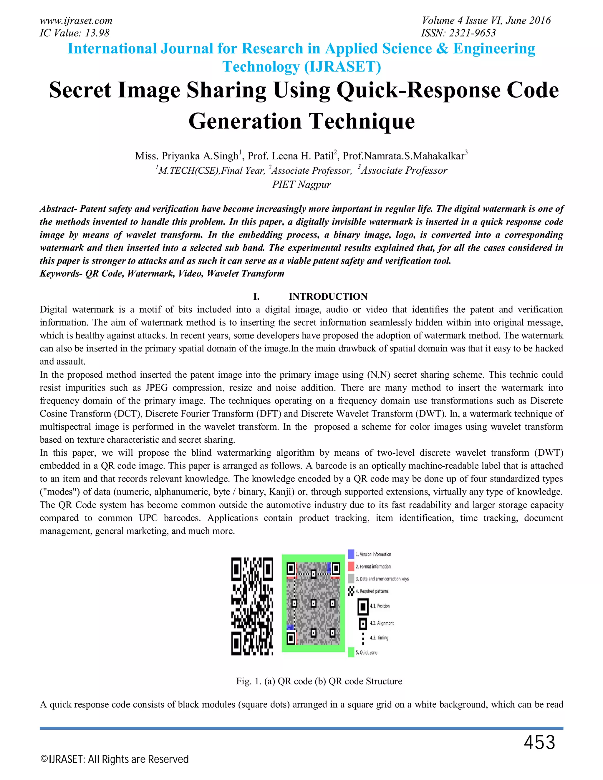
www.ijraset.com Volume 4 Issue VI, June 2016
IC Value: 13.98 ISSN: 2321-9653
International Journal for Research in Applied Science & Engineering
Technology (IJRASET)
©IJRASET: All Rights are Reserved
453
Secret Image Sharing Using Quick-Response Code
Generation Technique
Miss. Priyanka A.Singh1
, Prof. Leena H. Patil2
, Prof.Namrata.S.Mahakalkar3
1
M.TECH(CSE),Final Year, 2
Associate Professor, 3
Associate Professor
PIET Nagpur
Abstract- Patent safety and verification have become increasingly more important in regular life. The digital watermark is one of
the methods invented to handle this problem. In this paper, a digitally invisible watermark is inserted in a quick response code
image by means of wavelet transform. In the embedding process, a binary image, logo, is converted into a corresponding
watermark and then inserted into a selected sub band. The experimental results explained that, for all the cases considered in
this paper is stronger to attacks and as such it can serve as a viable patent safety and verification tool.
Keywords- QR Code, Watermark, Video, Wavelet Transform
I. INTRODUCTION
Digital watermark is a motif of bits included into a digital image, audio or video that identifies the patent and verification
information. The aim of watermark method is to inserting the secret information seamlessly hidden within into original message,
which is healthy against attacks. In recent years, some developers have proposed the adoption of watermark method. The watermark
can also be inserted in the primary spatial domain of the image.In the main drawback of spatial domain was that it easy to be hacked
and assault.
In the proposed method inserted the patent image into the primary image using (N,N) secret sharing scheme. This technic could
resist impurities such as JPEG compression, resize and noise addition. There are many method to insert the watermark into
frequency domain of the primary image. The techniques operating on a frequency domain use transformations such as Discrete
Cosine Transform (DCT), Discrete Fourier Transform (DFT) and Discrete Wavelet Transform (DWT). In, a watermark technique of
multispectral image is performed in the wavelet transform. In the proposed a scheme for color images using wavelet transform
based on texture characteristic and secret sharing.
In this paper, we will propose the blind watermarking algorithm by means of two-level discrete wavelet transform (DWT)
embedded in a QR code image. This paper is arranged as follows. A barcode is an optically machine-readable label that is attached
to an item and that records relevant knowledge. The knowledge encoded by a QR code may be done up of four standardized types
("modes") of data (numeric, alphanumeric, byte / binary, Kanji) or, through supported extensions, virtually any type of knowledge.
The QR Code system has become common outside the automotive industry due to its fast readability and larger storage capacity
compared to common UPC barcodes. Applications contain product tracking, item identification, time tracking, document
management, general marketing, and much more.
Fig. 1. (a) QR code (b) QR code Structure
A quick response code consists of black modules (square dots) arranged in a square grid on a white background, which can be read
www.ijraset.com Volume 4 Issue VI, June 2016
IC Value: 13.98 ISSN: 2321-9653
International Journal for Research in Applied Science & Engineering
Technology (IJRASET)
©IJRASET: All Rights are Reserved
454
by an imaging apparatus, such as a camera or mobile, and 13th International Symposium on Communications and Information
Technologies (ISCIT) 791 processed using Reed-Solomon error correction up to that the image can be appropriately changed.
knowledge is then extracted from the motif present in both horizontal and vertical components of the image. Fig. 1(a) shown the
example of QR code and the structure of QR code shown in Fig. 1(b)
A. Modules
1) Level DWT for creating sub bands: Discrete Wavelet transform (DWT) is a mathematical tool for hierarchically decomposing
an image. It is useful for processing of non-stationary signals. The transform is based on small waves, called wavelets, of
varying frequency and limited duration. Wavelet transform provides both frequency and spatial description of an image. Unlike
conventional Fourier transform, temporal information is retained in this transformation process. DWT is the multi-resolution
description of an image the decoding can be processed sequentially from a low resolution to the higher resolution. The DWT
splits the signal into high and low frequency components and the high frequency part contains information about the edge
components, while the low frequency part is split again into high and low frequency parts. In two dimensional applications, for
each level of decomposition, we first perform the DWT in the vertical direction, followed by the DWT in the horizontal
direction. After the first level of decomposition, there are 4 sub-bands: LL1, LH1, HL1, and HH1. For each successive level of
decomposition, the LL sub-band of the previous level is used as the input. To perform second level decomposition, the DWT is
applied to LL1 band which decomposes the LL1 band into the four sub-bands LL2, LH2, HL2, and HH2. To perform third level
decomposition, the DWT is applied to LL2 band which decompose this band into the four sub-bands – LL3, LH3, HL3, HH3.
This results in 10 sub-bands per component. LH1, HL1, and HH1 contain the highest frequency bands present in the image tile,
while LL3 contains the lowest frequency band
Fig.2.2-Level discrete Wavelet Transform
2) Watermark embedding in original image: A binary image of Burapha University logo, is a selected as the watermark. The
process of inserting this watermark was performed on a QR code image on its frequency domain. The QR code image was first
decomposed by a two-level two-dimensional wavelet transform as shown inFig.2. The following watermark extraction, are
bided in a sense that it did not want the primary QR code image in order to get the embedding watermark. There were two steps
in our algorithm: watermark embedding and watermark extraction.
The step of embedding process are outlined as follows Step of watermark image with secret key
I The watermark image was produced as a bit sequence of watermark S. The information and background contains were set to 1 and
–1, respectively.
S={si,1<=i<=N}.si ε{-1,1} (1)
where N is the total number of pictures-cells in the watermark image The pseudo-random sequence (P) whose each digit can take a
value either 1 or –1 was randomly generated with a secret key for embedding and extracting of the watermark.
P={pi,1<=i<=M},pi ε {-1,1} (2)
Step of QR code image
a) The two-level DWT of M x M image ( ) ti was computed for quick response code image.
b) A watermark was then embedded in sub band LH2 orHL2 or HH2. According to the rule
ti = ti + α.pi.si,I = 1,2,3……..N
www.ijraset.com Volume 4 Issue VI, June 2016
IC Value: 13.98 ISSN: 2321-9653
International Journal for Research in Applied Science & Engineering
Technology (IJRASET)
©IJRASET: All Rights are Reserved
455
Where is input image. ′ is output image with watermark. α is a magnitude factor which is a unchanged determining the
watermark power.
c) After that, the inverse DWT (IDWT) was then applied to obtain the watermarked image.
d) Compute PSNR
Fig.3. Watermark embedding process
3) Neural Network Training &Generation Of QR code: In information technology, a neural network is a system of programs
and data structures that approximates the operation of the human brain. A neural network usually involves a large number of
processors operating in parallel, each with its own small sphere of knowledge and access to data in its local memory. Typically,
a neural network is initially "trained" or fed large amounts of data and rules about data relationships (for example, "A
grandfather is older than a person's father"). A program can then tell the network how to behave in response to an external
stimulus (for example, to input from a computer user who is interacting with the network) or can initiate activity on its own
(within the limits of its access to the external world). Much has been said about 2D barcodes, and the discussion has focused on
the format of the 2D barcode itself – QRCode, Data Matrix, and so on. But equally important is the format of what the barcode
itself encodes.2D barcodes encode text, generally, but that text can represent many things. Commonly, 2D barcodes encode text
that represents a URL, like http://google.com/m. This is a special string of text since it is recognizable as a URL by readers, and
therefore can be acted upon: the reader can open the URL in a browser.2D barcodes can encode many types of actionable text.
Text representing contact information, when recognized, could trigger a prompt to add the contact to an address book. But this
only works when readers understand that text encodes contact information. For this, we need standards too. There are some
standards -- de facto and otherwise -- already in use. This wiki attempts to catalog some possible standards for encoding
various types of information, and suggest a standard action associated to them. It is not necessarily complete and contributions
are welcome. The ZXing
www.ijraset.com Volume 4 Issue VI, June 2016
IC Value: 13.98 ISSN: 2321-9653
International Journal for Research in Applied Science & Engineering
Technology (IJRASET)
©IJRASET: All Rights are Reserved
456
Fig. Generated QR images
4) Watermark Extraction Process: The watermark extraction algorithm didn’t used the primary QR code image. A assumption of
the original value of the picture-cell is however required. Thus, a assumption of the primary value of the pixels was performed
using noise reduction technique. In this paper, we use an averaging3×3mask whose elements were fixed to 1/9. The extraction
process are outlined as follows (Fig.4).The predicted image ti could be gained by smoothing the input image ti
*
with a spatial
convolution mask. The prediction of the primary value can be defined as:
where c is the size of the convolution cover.
a) The watermarked image and the predicted image were DWT converted independently.
b) The estimate of the Si҇ is indicated by the difference between t* and ҇҇ti
δ =t*i-ti҇=α.pi.si (5)
c) The sign of the difference between the assumption and the actual value is the value of the embedded bit:
Sgn (δi )=pi.si (6)
d) Compute NC
The watermark was then appraise by multiplying pseudo- random number to the embedded bit. If wrong pseudo random series was
to be used, the scheme should not work.
Fig.4. Watermark Extraction Process
II. CONCLUSION AND FUTURE SCOPE
In the proposed Digital watermarking method, a binary image is watermarked into a quick response Code image. The inserting
process is in LH, HL and HH sub bands based on wavelet transform. The algorithm explain that the watermark with an acceptable
visual quality can be get easily. In future we try to find more efficient ways for more series attacks such as stronger noise, high
compression and geometric distortion etc.
In future work we focus on enhanced the proposed method for more inserting capacity and also for embedding secret data in audio
or video file. In future there is a scope to build a better method for QR Code image depending on the above theoretical knowledge
and the current method available and also reduce the degradation of image quality.
REFERENCES
[1] R. Z. Wang, Y. C. Lan, Y. K. Lee, S. Y. Huang, S. J. Shyu, and T. L. Chia, “Incrementing visual cryptography using random grids,” Opt. Commun., vol. 283,
no. 21, pp. 4242–4249, Nov. 2010.
[2] P. L. Chiu and K. H. Lee, “A simulated annealing algorithm for general threshold visual cryptography schemes,” IEEE Trans. Inf. Forensics Security, vol. 6,
www.ijraset.com Volume 4 Issue VI, June 2016
IC Value: 13.98 ISSN: 2321-9653
International Journal for Research in Applied Science & Engineering
Technology (IJRASET)
©IJRASET: All Rights are Reserved
457
no. 3, pp. 992–1001, Sep. 2011.
[3] Kang, G. R. Arce, and H. K. Lee, “Color extended visual cryptography using error diffusion,” IEEE Trans. Image Process., vol. 20, no. 1,132–145, Jan. 2011.
[4] M. Kim, D. Li, and S. Hong, A Robust and Invisible Digital Watermarking Algorithm based on Multiple Transform Method for Image Contents :Proceedings
of the World Congress on Engineering and Computer Science 2013 Vol I WCECS 2013, 23-25 October, 2013, San Francisco, USA.
[5] C. Guo, C. C. Chang, and C. Qin, “A multi-threshold secret image sharing scheme based on MSP,” Pattern Recognit. Lett., vol. 33, no. 12, pp. 1594–1600, Sep.
2012.
[6] K. H. Lee and P. L. Chiu, “An extended visual cryptography algorithm for general access structures,” IEEE Trans. Inf. Forensics Security, vol. 7, no. 1, pp.
219–229, Feb. 2012.
[7] Frank Y. Shih: Digital watermarking and steganography: fundamentals and techniques. Taylor & Francis, Boca Raton, FL, USA, 2008.
[8] Jun-Chou Chuang, Yu-Chen Hu & Hsien-Ju Ko. A Novel Secret Sharing Technique using QR Code, International Journal of Image Processing (IJIP), Volume :
Issue (5),pp. 468-475, 2010.
[9] J. Fridrich, M. Goljan, and D. Soukal, “Perturbed quantization steganog-raphy with wet paper codes,” in Proc. Workshop Multimedia Sec., Magdeburg,
Germany, Sep. 2004, pp. 4–15.
[10] Sushma Yalamanchili, M. Kameswara Rao, “Copyright Protection of Gray Scale Images by Watermarking Technique using (N,N) Secret Sharing Scheme,”
Journal of Emerging Technologies in Web Intelligence, Vol 2, No 2, pp.101-105, May 2010.
[11] Y. Rangsanseri, J. Panyaveraporn and P. Thitimajshima, “PCA/Wavelet Based Watermarking of Multispectral Images,” 2005 International Symposium on
Remote Sensing (ISRS2005), Korea, 12-14 Oct. 2005.
[12] Nagaraj V. Dharwadkar and B.B.Amberker, “Watermarking Scheme for Color Images using Wavelet Transform based Texture Properties and Secret Sharing,”
International Journal of Information and Communication Engineering,Vol 6, No 2,pp 94-101, 2010.
[13] R.Z.Wang,Y.C.Lan,Y. K. Lee, S. Y. Huang, S. J. Shyu, and T. L. Chia, “Incrementing visual cryptography using random grids,” Opt. Commun., vol. 283, no.
21, pp. 4242–4249, Nov. 2010.
[14] P. L. Chiu and K. H. Lee, “A simulated annealing algorithm for general threshold visual cryptography schemes,” IEEE Trans. Inf. Forensics Security, vol. 6,
no. 3, pp. 992–1001, Sep. 2011.
[15] Y. Rangsanseri, J. Panyaveraporn and P. Thitimajshima, “PCA/Wavelet Based Watermarking of Multispectral Images,” 2005 International Symposium on
Remote Sensing (ISRS2005), Korea, 12-14 Oct. 2005.
[16] G. Ateniese, C. Blundo, A. D. Santis, and D. R. Stinson, “Extended capabilities for visual cryptography,” Theoretical Comput. Sci., vol. 250, nos. 1–2, pp. 143–
161, Jan. 2001.
[17] F. Hartung, J.K. Su, and B. Girod, Spread Spectrum Watermarking: Malicious Attacks and Counter-Attacks, Proc. of SPIE Vol. 3657: Security and
Watermarking of Multimedia Contents, San Jose, CA, USA, Jan. 1999.

International Journal for Research in Applied Science & Engineering

  • 1.
    www.ijraset.com Volume 4Issue VI, June 2016 IC Value: 13.98 ISSN: 2321-9653 International Journal for Research in Applied Science & Engineering Technology (IJRASET) ©IJRASET: All Rights are Reserved 453 Secret Image Sharing Using Quick-Response Code Generation Technique Miss. Priyanka A.Singh1 , Prof. Leena H. Patil2 , Prof.Namrata.S.Mahakalkar3 1 M.TECH(CSE),Final Year, 2 Associate Professor, 3 Associate Professor PIET Nagpur Abstract- Patent safety and verification have become increasingly more important in regular life. The digital watermark is one of the methods invented to handle this problem. In this paper, a digitally invisible watermark is inserted in a quick response code image by means of wavelet transform. In the embedding process, a binary image, logo, is converted into a corresponding watermark and then inserted into a selected sub band. The experimental results explained that, for all the cases considered in this paper is stronger to attacks and as such it can serve as a viable patent safety and verification tool. Keywords- QR Code, Watermark, Video, Wavelet Transform I. INTRODUCTION Digital watermark is a motif of bits included into a digital image, audio or video that identifies the patent and verification information. The aim of watermark method is to inserting the secret information seamlessly hidden within into original message, which is healthy against attacks. In recent years, some developers have proposed the adoption of watermark method. The watermark can also be inserted in the primary spatial domain of the image.In the main drawback of spatial domain was that it easy to be hacked and assault. In the proposed method inserted the patent image into the primary image using (N,N) secret sharing scheme. This technic could resist impurities such as JPEG compression, resize and noise addition. There are many method to insert the watermark into frequency domain of the primary image. The techniques operating on a frequency domain use transformations such as Discrete Cosine Transform (DCT), Discrete Fourier Transform (DFT) and Discrete Wavelet Transform (DWT). In, a watermark technique of multispectral image is performed in the wavelet transform. In the proposed a scheme for color images using wavelet transform based on texture characteristic and secret sharing. In this paper, we will propose the blind watermarking algorithm by means of two-level discrete wavelet transform (DWT) embedded in a QR code image. This paper is arranged as follows. A barcode is an optically machine-readable label that is attached to an item and that records relevant knowledge. The knowledge encoded by a QR code may be done up of four standardized types ("modes") of data (numeric, alphanumeric, byte / binary, Kanji) or, through supported extensions, virtually any type of knowledge. The QR Code system has become common outside the automotive industry due to its fast readability and larger storage capacity compared to common UPC barcodes. Applications contain product tracking, item identification, time tracking, document management, general marketing, and much more. Fig. 1. (a) QR code (b) QR code Structure A quick response code consists of black modules (square dots) arranged in a square grid on a white background, which can be read
  • 2.
    www.ijraset.com Volume 4Issue VI, June 2016 IC Value: 13.98 ISSN: 2321-9653 International Journal for Research in Applied Science & Engineering Technology (IJRASET) ©IJRASET: All Rights are Reserved 454 by an imaging apparatus, such as a camera or mobile, and 13th International Symposium on Communications and Information Technologies (ISCIT) 791 processed using Reed-Solomon error correction up to that the image can be appropriately changed. knowledge is then extracted from the motif present in both horizontal and vertical components of the image. Fig. 1(a) shown the example of QR code and the structure of QR code shown in Fig. 1(b) A. Modules 1) Level DWT for creating sub bands: Discrete Wavelet transform (DWT) is a mathematical tool for hierarchically decomposing an image. It is useful for processing of non-stationary signals. The transform is based on small waves, called wavelets, of varying frequency and limited duration. Wavelet transform provides both frequency and spatial description of an image. Unlike conventional Fourier transform, temporal information is retained in this transformation process. DWT is the multi-resolution description of an image the decoding can be processed sequentially from a low resolution to the higher resolution. The DWT splits the signal into high and low frequency components and the high frequency part contains information about the edge components, while the low frequency part is split again into high and low frequency parts. In two dimensional applications, for each level of decomposition, we first perform the DWT in the vertical direction, followed by the DWT in the horizontal direction. After the first level of decomposition, there are 4 sub-bands: LL1, LH1, HL1, and HH1. For each successive level of decomposition, the LL sub-band of the previous level is used as the input. To perform second level decomposition, the DWT is applied to LL1 band which decomposes the LL1 band into the four sub-bands LL2, LH2, HL2, and HH2. To perform third level decomposition, the DWT is applied to LL2 band which decompose this band into the four sub-bands – LL3, LH3, HL3, HH3. This results in 10 sub-bands per component. LH1, HL1, and HH1 contain the highest frequency bands present in the image tile, while LL3 contains the lowest frequency band Fig.2.2-Level discrete Wavelet Transform 2) Watermark embedding in original image: A binary image of Burapha University logo, is a selected as the watermark. The process of inserting this watermark was performed on a QR code image on its frequency domain. The QR code image was first decomposed by a two-level two-dimensional wavelet transform as shown inFig.2. The following watermark extraction, are bided in a sense that it did not want the primary QR code image in order to get the embedding watermark. There were two steps in our algorithm: watermark embedding and watermark extraction. The step of embedding process are outlined as follows Step of watermark image with secret key I The watermark image was produced as a bit sequence of watermark S. The information and background contains were set to 1 and –1, respectively. S={si,1<=i<=N}.si ε{-1,1} (1) where N is the total number of pictures-cells in the watermark image The pseudo-random sequence (P) whose each digit can take a value either 1 or –1 was randomly generated with a secret key for embedding and extracting of the watermark. P={pi,1<=i<=M},pi ε {-1,1} (2) Step of QR code image a) The two-level DWT of M x M image ( ) ti was computed for quick response code image. b) A watermark was then embedded in sub band LH2 orHL2 or HH2. According to the rule ti = ti + α.pi.si,I = 1,2,3……..N
  • 3.
    www.ijraset.com Volume 4Issue VI, June 2016 IC Value: 13.98 ISSN: 2321-9653 International Journal for Research in Applied Science & Engineering Technology (IJRASET) ©IJRASET: All Rights are Reserved 455 Where is input image. ′ is output image with watermark. α is a magnitude factor which is a unchanged determining the watermark power. c) After that, the inverse DWT (IDWT) was then applied to obtain the watermarked image. d) Compute PSNR Fig.3. Watermark embedding process 3) Neural Network Training &Generation Of QR code: In information technology, a neural network is a system of programs and data structures that approximates the operation of the human brain. A neural network usually involves a large number of processors operating in parallel, each with its own small sphere of knowledge and access to data in its local memory. Typically, a neural network is initially "trained" or fed large amounts of data and rules about data relationships (for example, "A grandfather is older than a person's father"). A program can then tell the network how to behave in response to an external stimulus (for example, to input from a computer user who is interacting with the network) or can initiate activity on its own (within the limits of its access to the external world). Much has been said about 2D barcodes, and the discussion has focused on the format of the 2D barcode itself – QRCode, Data Matrix, and so on. But equally important is the format of what the barcode itself encodes.2D barcodes encode text, generally, but that text can represent many things. Commonly, 2D barcodes encode text that represents a URL, like http://google.com/m. This is a special string of text since it is recognizable as a URL by readers, and therefore can be acted upon: the reader can open the URL in a browser.2D barcodes can encode many types of actionable text. Text representing contact information, when recognized, could trigger a prompt to add the contact to an address book. But this only works when readers understand that text encodes contact information. For this, we need standards too. There are some standards -- de facto and otherwise -- already in use. This wiki attempts to catalog some possible standards for encoding various types of information, and suggest a standard action associated to them. It is not necessarily complete and contributions are welcome. The ZXing
  • 4.
    www.ijraset.com Volume 4Issue VI, June 2016 IC Value: 13.98 ISSN: 2321-9653 International Journal for Research in Applied Science & Engineering Technology (IJRASET) ©IJRASET: All Rights are Reserved 456 Fig. Generated QR images 4) Watermark Extraction Process: The watermark extraction algorithm didn’t used the primary QR code image. A assumption of the original value of the picture-cell is however required. Thus, a assumption of the primary value of the pixels was performed using noise reduction technique. In this paper, we use an averaging3×3mask whose elements were fixed to 1/9. The extraction process are outlined as follows (Fig.4).The predicted image ti could be gained by smoothing the input image ti * with a spatial convolution mask. The prediction of the primary value can be defined as: where c is the size of the convolution cover. a) The watermarked image and the predicted image were DWT converted independently. b) The estimate of the Si҇ is indicated by the difference between t* and ҇҇ti δ =t*i-ti҇=α.pi.si (5) c) The sign of the difference between the assumption and the actual value is the value of the embedded bit: Sgn (δi )=pi.si (6) d) Compute NC The watermark was then appraise by multiplying pseudo- random number to the embedded bit. If wrong pseudo random series was to be used, the scheme should not work. Fig.4. Watermark Extraction Process II. CONCLUSION AND FUTURE SCOPE In the proposed Digital watermarking method, a binary image is watermarked into a quick response Code image. The inserting process is in LH, HL and HH sub bands based on wavelet transform. The algorithm explain that the watermark with an acceptable visual quality can be get easily. In future we try to find more efficient ways for more series attacks such as stronger noise, high compression and geometric distortion etc. In future work we focus on enhanced the proposed method for more inserting capacity and also for embedding secret data in audio or video file. In future there is a scope to build a better method for QR Code image depending on the above theoretical knowledge and the current method available and also reduce the degradation of image quality. REFERENCES [1] R. Z. Wang, Y. C. Lan, Y. K. Lee, S. Y. Huang, S. J. Shyu, and T. L. Chia, “Incrementing visual cryptography using random grids,” Opt. Commun., vol. 283, no. 21, pp. 4242–4249, Nov. 2010. [2] P. L. Chiu and K. H. Lee, “A simulated annealing algorithm for general threshold visual cryptography schemes,” IEEE Trans. Inf. Forensics Security, vol. 6,
  • 5.
    www.ijraset.com Volume 4Issue VI, June 2016 IC Value: 13.98 ISSN: 2321-9653 International Journal for Research in Applied Science & Engineering Technology (IJRASET) ©IJRASET: All Rights are Reserved 457 no. 3, pp. 992–1001, Sep. 2011. [3] Kang, G. R. Arce, and H. K. Lee, “Color extended visual cryptography using error diffusion,” IEEE Trans. Image Process., vol. 20, no. 1,132–145, Jan. 2011. [4] M. Kim, D. Li, and S. Hong, A Robust and Invisible Digital Watermarking Algorithm based on Multiple Transform Method for Image Contents :Proceedings of the World Congress on Engineering and Computer Science 2013 Vol I WCECS 2013, 23-25 October, 2013, San Francisco, USA. [5] C. Guo, C. C. Chang, and C. Qin, “A multi-threshold secret image sharing scheme based on MSP,” Pattern Recognit. Lett., vol. 33, no. 12, pp. 1594–1600, Sep. 2012. [6] K. H. Lee and P. L. Chiu, “An extended visual cryptography algorithm for general access structures,” IEEE Trans. Inf. Forensics Security, vol. 7, no. 1, pp. 219–229, Feb. 2012. [7] Frank Y. Shih: Digital watermarking and steganography: fundamentals and techniques. Taylor & Francis, Boca Raton, FL, USA, 2008. [8] Jun-Chou Chuang, Yu-Chen Hu & Hsien-Ju Ko. A Novel Secret Sharing Technique using QR Code, International Journal of Image Processing (IJIP), Volume : Issue (5),pp. 468-475, 2010. [9] J. Fridrich, M. Goljan, and D. Soukal, “Perturbed quantization steganog-raphy with wet paper codes,” in Proc. Workshop Multimedia Sec., Magdeburg, Germany, Sep. 2004, pp. 4–15. [10] Sushma Yalamanchili, M. Kameswara Rao, “Copyright Protection of Gray Scale Images by Watermarking Technique using (N,N) Secret Sharing Scheme,” Journal of Emerging Technologies in Web Intelligence, Vol 2, No 2, pp.101-105, May 2010. [11] Y. Rangsanseri, J. Panyaveraporn and P. Thitimajshima, “PCA/Wavelet Based Watermarking of Multispectral Images,” 2005 International Symposium on Remote Sensing (ISRS2005), Korea, 12-14 Oct. 2005. [12] Nagaraj V. Dharwadkar and B.B.Amberker, “Watermarking Scheme for Color Images using Wavelet Transform based Texture Properties and Secret Sharing,” International Journal of Information and Communication Engineering,Vol 6, No 2,pp 94-101, 2010. [13] R.Z.Wang,Y.C.Lan,Y. K. Lee, S. Y. Huang, S. J. Shyu, and T. L. Chia, “Incrementing visual cryptography using random grids,” Opt. Commun., vol. 283, no. 21, pp. 4242–4249, Nov. 2010. [14] P. L. Chiu and K. H. Lee, “A simulated annealing algorithm for general threshold visual cryptography schemes,” IEEE Trans. Inf. Forensics Security, vol. 6, no. 3, pp. 992–1001, Sep. 2011. [15] Y. Rangsanseri, J. Panyaveraporn and P. Thitimajshima, “PCA/Wavelet Based Watermarking of Multispectral Images,” 2005 International Symposium on Remote Sensing (ISRS2005), Korea, 12-14 Oct. 2005. [16] G. Ateniese, C. Blundo, A. D. Santis, and D. R. Stinson, “Extended capabilities for visual cryptography,” Theoretical Comput. Sci., vol. 250, nos. 1–2, pp. 143– 161, Jan. 2001. [17] F. Hartung, J.K. Su, and B. Girod, Spread Spectrum Watermarking: Malicious Attacks and Counter-Attacks, Proc. of SPIE Vol. 3657: Security and Watermarking of Multimedia Contents, San Jose, CA, USA, Jan. 1999.