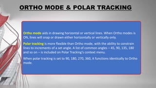
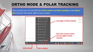
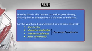
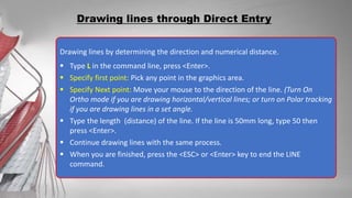
This document provides instructions for using the LINE command in AutoCAD to draw straight line segments. There are four ways to access the LINE command: through toolbars, pull-down menus, command line, or buttons. When using LINE, points are specified by clicking in the graphics window or entering coordinates. Options like ortho mode and polar tracking can help constrain angles of lines drawn.


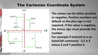
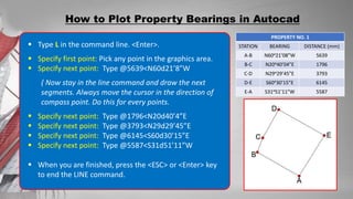
![After first points entered, your next points can be entered by specifying the next
coordinate compare/relative from the first points. The relative coordinate started
with symbol “@” tell AutoCAD it was a relative coordinates. Using relative
coordinate, points entered by typing @x,y [Enter]
Note: relative coordinates are very useful in drawing rectangle.
Drawing lines through Relative Coordinates
Type L in the command line. <Enter>
Specify first point: Pick any point in the
graphics area.
Specify next point: Type @50,50
Specify next point: Type @0,25
Specify next point: Type @30,0
When you are finished, press the <ESC> or
<Enter> key to end the LINE command.](https://image.slidesharecdn.com/drawinglines-230614131302-f79d235e/85/DRAWING-LINES-pptx-16-320.jpg)
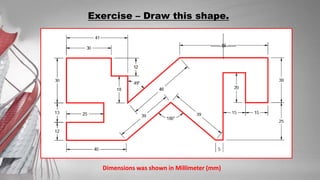
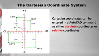
![Polar coordinates used when you need to draw the next points at specify angle.
Polar coordinates system in AutoCAD specifies distance length at which angle. Using
polar coordinate, points entered by typing @distance<angle [Enter]
Drawing lines through Polar Coordinates
Type L in the command line. (Enter>
Specify first point: Pick any point in the
graphics area.
Specify next point: Type @70<45
Specify next point: Type @25<90
Specify next point: Type @30<0
When you are finished, press the <ESC>
or <Enter> key to end the LINE
command.](https://image.slidesharecdn.com/drawinglines-230614131302-f79d235e/85/DRAWING-LINES-pptx-17-320.jpg)
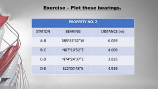
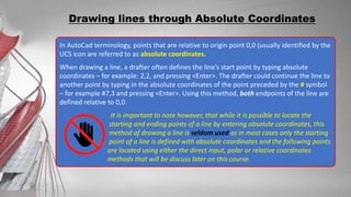
![How to Plot Property Bearings in Autocad
PROPERTY NO. 1
STATION BEARING DISTANCE (m)
A-B N60ᵒ21’08”W 5.639
B-C N20ᵒ40’04”E 1.796
C-D N29ᵒ29’45”E 3.793
D-E S60ᵒ30’15”E 6.145
E-A S31ᵒ51’11”W 5.587
CONVERSION
DISTANCE (mm)
5639
1796
3793
6145
5587
To plot this, points entered by typing @distance<Bearing [Enter]. Degree (ᵒ) will be
represented by letter d.
If your Drawing Units was set to Decimal, any entities that you will draw will be measured
in millimeters.
On this Property bearings, since the distance was shown in meters (m), you have to
convert and draw it in millimeters.](https://image.slidesharecdn.com/drawinglines-230614131302-f79d235e/85/DRAWING-LINES-pptx-18-320.jpg)