
Recommended
Recommended
More Related Content
What's hot
What's hot (18)
Similar to Download
Similar to Download (20)
Recently uploaded
Recently uploaded (20)
Download
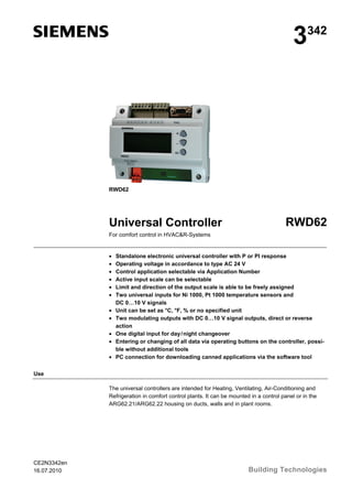
- 1. 3342 RWD62 Universal Controller RWD62 For comfort control in HVAC&R-Systems • Standalone electronic universal controller with P or PI response • Operating voltage in accordance to type AC 24 V • Control application selectable via Application Number • Active input scale can be selectable • Limit and direction of the output scale is able to be freely assigned • Two universal inputs for Ni 1000, Pt 1000 temperature sensors and DC 0…10 V signals • Unit can be set as °C, °F, % or no specified unit • Two modulating outputs with DC 0…10 V signal outputs, direct or reverse action • One digital input for day/night changeover • Entering or changing of all data via operating buttons on the controller, possi- ble without additional tools • PC connection for downloading canned applications via the software tool Use The universal controllers are intended for Heating, Ventilating, Air-Conditioning and Refrigeration in comfort control plants. It can be mounted in a control panel or in the ARG62.21/ARG62.22 housing on ducts, walls and in plant rooms. CE2N3342en 16.07.2010 Building Technologies
- 2. HVAC&R Application Measurement and control of temperature, relative humidity, absolute humidity, en- thalpy, pressure differential, volumetric airflow and indoor air quality. The input scale can be set from –100 units to 8,000 units. The start and end points of output voltage can be any value between DC 0 V to DC 10 V. Functions Summary • Controller Stand-alone controller with two DC 0…10 V outputs with independent adjustment on each sequence for direct acting and/or reverse acting. Adjustable parameters includ- ing proportional band and integral action time. • Auxiliary selectable function Universal input X2 for one of the following functions: − PI limiter function (absolute and relative) − Remote setpoint function − Cascade control function − Setpoint compensation − Winter/summer operation − Maximum priority • Digital input D1 for setpoint changeover day/night Type summary Inputs Outputs Type Reference Universal Digital Analog Digital 2 1 2 0 RWD62 Name Type Protective small enclosure for wall mounting ARG62.21 Protective big enclosure for wall mounting ARG62.22 Software Tool S3341A031EN0 Accessories Equipment combinations The following Siemens units can be connected to RWD62 universal controller. Units Data sheet no. Sensor with LG-Ni 1000 temperature sensing element 17… to 19… Sensor with Pt 1000 temperature sensing element 1846 Sensor with DC 0…10 V measuring signal 17… to 19… Room temperature sensor with setpoint adjuster QAA25 or QAA25/AP 1721 / 1748 Remote setpoint adjusters FZA21.11 and FZA61.11 19… Air damper actuators with DC 0…10 V input 46… Valve actuators with DC 0…10 V input 45… Control valves 46… Signal converter SEM 61.4 for current valve control 51… Various signal converters 34… 2/10 Siemens RWD62 Universal controller CE2N3342en Building Technologies 16.07.2010
- 3. Other combinations with third-party units are possible, provided the input and output specifications match the RWD62. Software Tool A software tool for controller application selection and parameter adjustment is avail- able. It is a user-friendly Windows® 95 (or above) based software tool which provides you a printout of the controller settings. Functions Controller type The RWD62 is a stand-alone universal controller, which performs both primary and auxiliary control functions. The respective mode is defined by entering the correspond- ing configuration and setting parameters via the push buttons on the controller or the software tool. Main functions The RWD62 controller can be programmed as follows: One sequence: Y1 or Y2 reverse or direct acting Two sequence: Y1 and Y2 reverse and direct acting or Y1 and Y2 reverse and reverse acting or Y1 and Y2 direct and direct acting Y1 Output Voltage Setpoint Load 3342d01 3342d02 Y1 Output Voltage Load Y2 Setpoint Reverse acting sequence (application no.: 10…19) 2 Reverse acting sequences (application no.: 20…29) Y1 Setpoint Load Y2 3342d03 Output Voltage Y1 Setpoint Load 3342d04 Output Voltage Reverse and direct acting sequences (application no.: 30…39) Direct acting sequence (application no.: 40…49) 3342d05 Output Voltage Y1 Setpoint Load Y2 2 Direct acting sequences (application no.: 50…59) 3/10 Siemens RWD62 Universal controller CE2N3342en Building Technologies 16.07.2010
- 4. The universal input X1 is used as the primary input for a LG- Ni 1000 temperature sen- sor, a Pt 1000 temperature sensor or a DC 0…10 V active input. Universal input X1 The universal input X2 is used as the secondary input for a LG-Ni 1000 temperature sensor, a Pt 1000 temperature sensor, an active/passive remote setpoint transmitter or a DC 0…10 V active input. Universal input X2 Digital input D1 The digital input D1 is used to select the day or night changeover. Changeover occurs via potential-free contacts between D1 and M. Analog outputs Each output Y (Y1, Y2) can be configured for either reverse or direct acting. The modu- lating voltage output (Y…) controls the devices requiring a DC 0…10 V signal. Ventilating plant with temperature control X1 Room temperature Y1 Heating, reverse action Y2 Cooling, direct action X1Y2Y1 Temp. RWD62 Y 3342s01 Example Auxiliary functions One of the following auxiliary functions can be selected: • PI limiter function (absolute and relative) • Remote setpoint function • Cascade control function • Setpoint compensation • Winter/summer operation • Maximum priority Additionally, the day and night operation mode is available. The limiter function with PI control enables absolute (or relative) maximum or minimum limitation of the supply air temperature (X2). When the value drops below or exceeds the limiter setpoint, the limiter function controls and takes priority over the main setpoint. X1Y2Y1 Temp. RWD62 Y X2 3342s02 PI limiter function A remote setpoint transmitter (FZA21.11, QAA25 or QAA25/AP), connected to X2 and configured accord- ingly, enables setpoint adjustment. Active measurement from 0…10 V DC corresponding adjustable range from –100 to 8000 Passive measurement from 0…1000 Ω corresponding adjustable range from –100 to 8000 X1Y2Y1 Temp. RWD62 Y X2 3342s03 Remote setpoint 4/10 Siemens RWD62 Universal controller CE2N3342en Building Technologies 16.07.2010
- 5. X2 Supply air temperature sensor You can select the PI/PI room/supply air temperature cascade control. In this case, the virtual PI room temperature controller determines the setpoint within the limiter setpoints for the PI supply air temperature controller. X1Y2Y1 Temp. RWD62 Y X2 3342s04 Cascade control Maximum priority Maximum priority, cooling If the value (0…10 V) of the input X2 is greater than the calculated output of the cooling sequence, the output will use the X2 input value as output value. This is active even when the controller is working with the heating sequence. X2Y2Y1 Temp. RWD62 Y X1 3342s05 The temperature setpoint X1 is shifted by the tem- perature as measured at sensor X2. Configuration of the RWD62 defines the influence on setpoint X1. The example shows the room air temperature setpoint as controlled by the outside temperature. 3342s06 X2Y1 Temp. RWD62 Y X1 Setpoint compensation A digital switch or analogue input between termi- nals X2 and M can be used to implement win- ter/summer changeover. Digital changeover When the contact is closed, summer operation is selected. Reverse acting output (Y1 only) is set to direct action (cooling). Analog changeover When the X2 input exceeds the setpoint, sum- mer operation is selected. Reverse acting output (Y1 only) is set to direct action (cooling). X1Y2Y1 Temp. RWD62 Y T X2 3342s07 Winter/summer operation Day/night setpoint A contact between terminals D1 and M can be used to implement setpoint changeover for day/night operation. When the contact is open, the setpoints for day operation are selected. When the contact is closed, the setpoints for night operation are selected. During the night mode, the following auxiliary func- tions are disabled: remote setpoint, abso- lute/relative limiter, setpoint compensation and maximum priority. X1Y2Y1 Temp. RWD62 Y D1 3342s08 5/10 Siemens RWD62 Universal controller CE2N3342en Building Technologies 16.07.2010
- 6. Mechanical design Housing The RWD62 universal controller is as per DIN 43 880 Gr. 1 requirements. Protective housing ARG62.21/ARG62.22 A protective housing is used to protect the controller when mounted outside a control panel, such as on ducts, walls and in plant rooms. Furthermore, the protective housing prevents inadvertent contact with voltage supplying parts such as the connecting termi- nals. The RWD62 clips into the protective housing. The cable entries are located at the top and the bottom of the protective housing. The front has an opening for the LCD display and the programming buttons. Mounting options The RWD62 universal controller can be mounted as follows: • In a standard electrical control cabinet as per DIN 43 880 • Wall mounted in a protective housing • Front mounting with standard available installation elements Terminals Plug-in screw terminals Operating and display elements The RWD62 is operated by the buttons on the controller front. Additional tools are not necessary. A 9-pin port is provided for optional programming via the software tool. 3342z01 LCD The LCD shows the following information for normal operation: • Current operating values (maximum 4 digits) • Current setpoints (day/night) • Application number • Output voltage value • Control sequencing diagram • Auxiliary input value • Selected auxiliary function The controller has three operating buttons for the following functions:Operating buttons The SELECT button is used to enter or save the value adjustment.SELECT The operating buttons are used for viewing and adjusting parameters. Configuration To configure the controller, follow the instructions supplied with the controller. 6/10 Siemens RWD62 Universal controller CE2N3342en Building Technologies 16.07.2010
- 7. Engineering notes Intended use Use this controller only for applications as described in the description on the title page (bold print) and the section "Use". Additionally, observe all conditions and restrictions imposed in this section and in "Technical data". The sections marked with a warning symbol contain technical safety requirements and restrictions. Observe all of these warnings as they directly relate to the protection of person and equipment. Installation notes Observe all local installation and mounting regulations. The RWD62 controllers can be mounted as follows: A On a top hat rail (EN60715, 35 × 7.5) at least 120 mm long B Wall mounted with 2 screws C Front mounted using standard elements, e.g. 1 × top hat rail 150 mm long 2 × hexagonal placeholders 50 mm washers and screws D In the ARG62.21/ARG62.22 protective housing Electrical installation Standard cables can be used for the controller. However, when mounting in an envi- ronment greatly exposed to EMI, use only shielded cables. The RWD62 is designed for AC 24 V operating voltage. The low voltage must comply with the requirements for safety extra-low voltage (SELV) as per EN 60730. Use safety insulating transformers with double insulation as per EN 60742; they must be designed for 100 % on-time. When using several transformers in one system, the connection terminals G0 must be galvanically connected. Supplying voltages above AC 24 V to low voltage connections may damage or destroy the controller or any other connected devices. Additionally, connections to voltages exceeding AC 42 V endanger personal safety. Commissioning notes A booklet is supplied with the RWD62 controller for commissioning. Observe the following: • The controller must be configured for plant-specific operation using standard applica- tion number • Plant specific fine tuning can be performed if required (refer to the commissioning booklet) • Power supply to the controller and the connected devices must be guaranteed • Values and settings entered remain available even on power failure 7/10 Siemens RWD62 Universal controller CE2N3342en Building Technologies 16.07.2010
- 8. 8/10 Siemens RWD62 Universal controller CE2N3342en Building Technologies 16.07.2010 Technical data Operating voltage Safety extra-low voltage (SELV) as per Frequency AC 24 V ±20 % EN 60730 50 Hz/60 Hz RWD62 2.5 VA Actual and nominal values 4 digits LG-Ni 1000 Pt 1000 Active sensor 0.5 °C 0.5 °C Depends on the setting range Transport Climatic conditions Temperature Humidity Mechanical conditions IEC721-3-2 Class 2K3 −25…+70 °C <95 % r.h. Class 2M2 Operation Climatic conditions Temperature Humidity IEC721-3-3 Class 3K5 0…+50 °C <95 % r.h. Housing Front and with ARG62.21 Front and with ARG62.22 IP 20 as per EN 60529 IP 30 as per EN 60529 IP 30 as per EN 60529 Automatic electrical controls for household and similar use EN 60730 In accordance with European Union directives Electromagnetic compatibility EMC Low voltage directive Emissions Immunity Safety 89/336 EEC 73/23 EEC EN 50081-1 EN 50082-1 EN 60730 N474 Screw terminals for cables with min. 0.5 mm dia. max. 2 x 1.5 mm2 or 2.5 mm2 RWD62 0.277 kg Controller measuring range Max. cable length for dia. 0.6 mm −50…+150 °C max. 300 m Controller measuring range Max. cable length for dia. 0.6 mm −20…+180 °C max. 300 m General data Power supply Power consumption LCD Display resolution for (these values do not relate to the controller accuracy) Environmental conditions Environmental conditions IP code Product standards conformity Other international approval Terminals Weight without packag- ing Analog inputs X1, X2 LG-Ni 1000 Ω at 0 °C Pt 1000 Ω at 0 °C
- 9. Range Max. cable length for dia. 0.6 mm DC 0…10 V corresponding to adjustable range from –100 to 8000 (°C, °F, % or no unit) max. 300 m Analog voltages (for measured variables in °C, % or without unit) Range Max. cable length for dia. 0.6 mm 0…1000 Ω corresponding to adjustable range from –100 to 8000 (°C, °F, % or no unit) max. 300 m Remote setpoints X2 Polling voltage for control commands (D…M) Current consumption DC 15 V <15 mA Digital input D1 Range Maximum current DC 0…10 V ±1 mA Analog outputs Y1, Y2 Internal diagram G0 RWD62 Y2 D1 M X1 M X2 MG MY1 M Tool 3342g01 D1 Digital input G, G0 AC 24 V supply ( SELV AC 24 V power supply) M Ground (G0) for signal inputs, universal inputs and analog outputs X1 Signal input (main input: LS Ni 1000, Pt 1000 and 0…10 V DC) X2 Signal input (aux. input: LS Ni 1000, Pt 1000, 0 …10 V DC and 0…1000 Ω or 0…10 V DC remote setpoint) Y1, Y2 Analog outputs Tool Communication port for PC (9-pin plug) Connection diagram N1 RWD62 controller PC Personal computer S1 Time clock or switch X1 Main input (Termination G appears when X1 is an active sensor) X2 Auxiliary input or remote setpoint (Termination G appears when X2 is an active sensor) Y1, Y2 Valve actuator 1 and 2 / damper actuator 1 and 2 9/10 Siemens RWD62 Universal controller CE2N3342en Building Technologies 16.07.2010
- 10. Please note that if you use a DESKTOP computer, the TOOL signal ground is gal- vanically connected to G0 inside the controller. If the signal line of the computer is grounded to Earth, the G0 line after TOOL connection will be Earthed as well. Note This will change from SELV to a PELV. Dimensions RWD62 ARG62.21 = 150 200 61.5 48.5 ARG62.22 = 345 ARG62.21 / ARG62.22 10/10 Siemens RWD62 Universal controller CE2N3342en 2001-2008 Siemens Switzerland Ltd Subject to alteration Building Technologies 16.07.2010