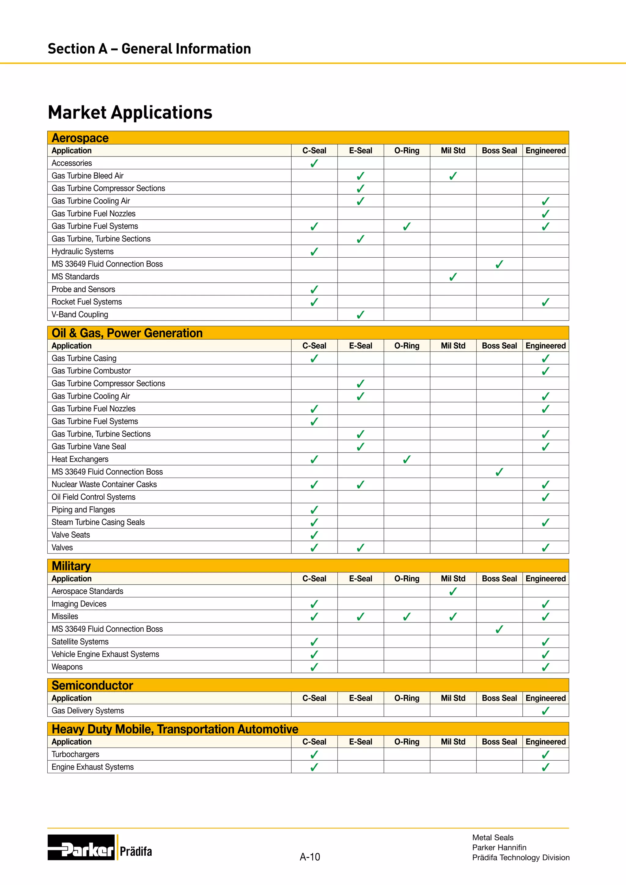
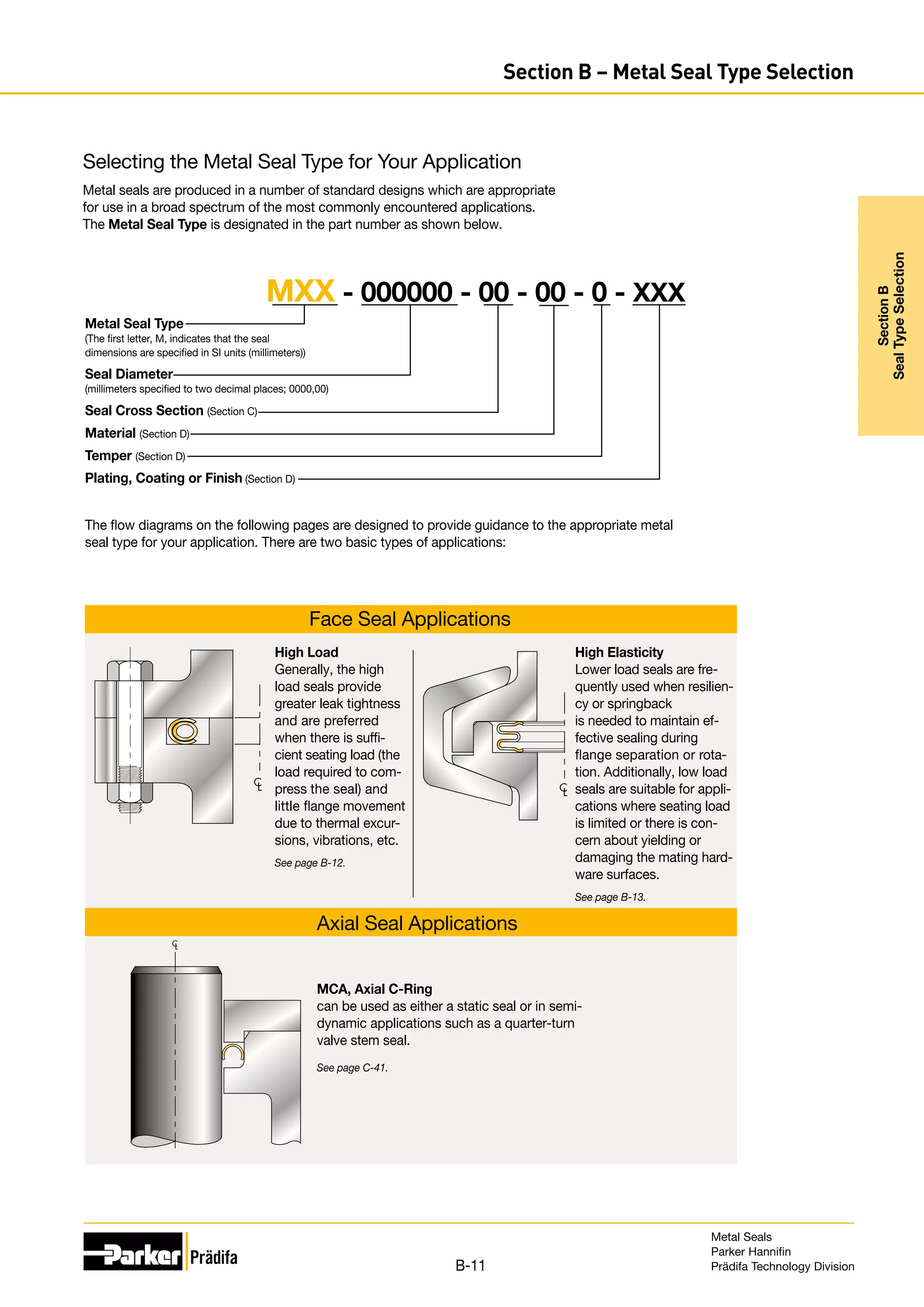
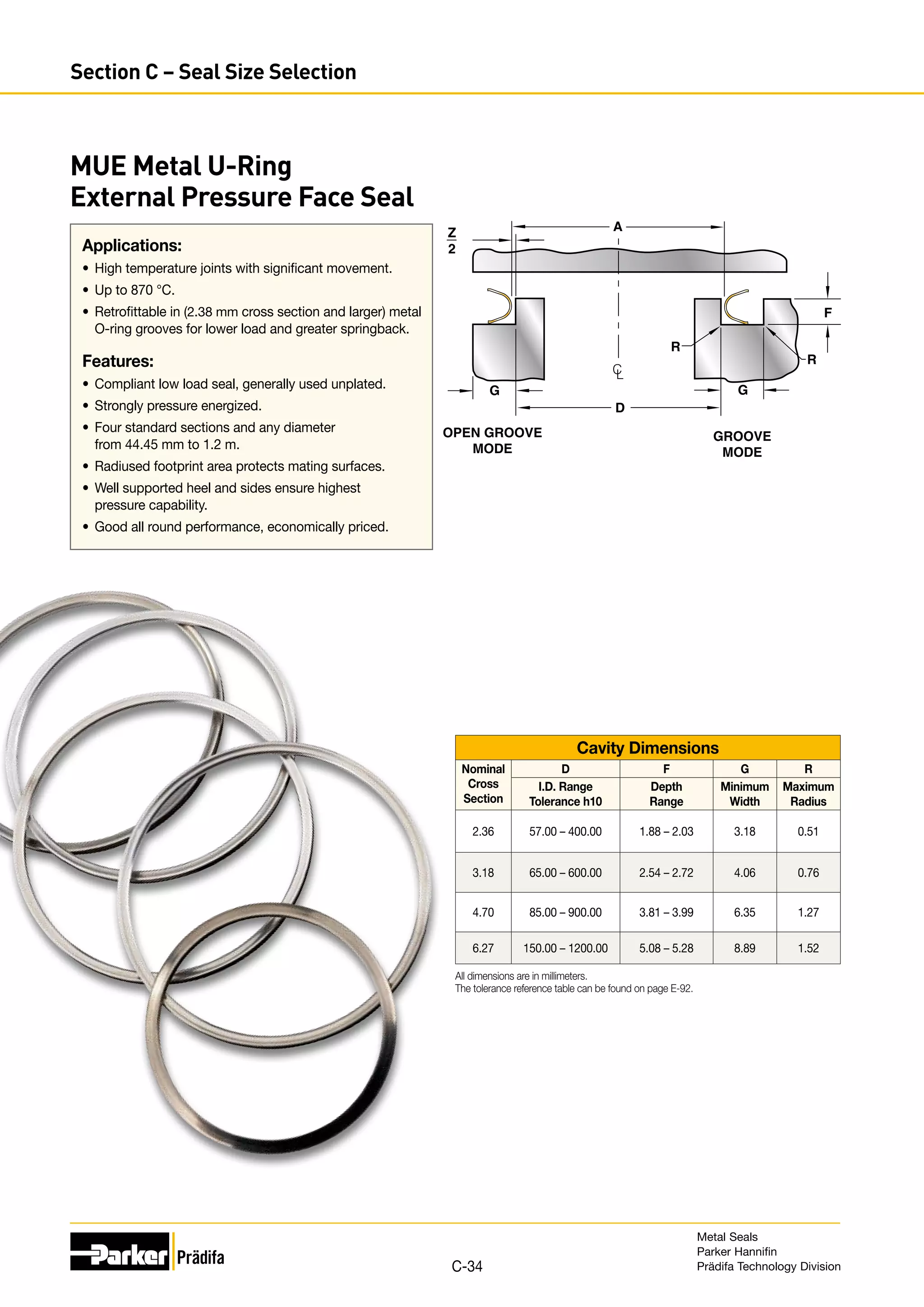
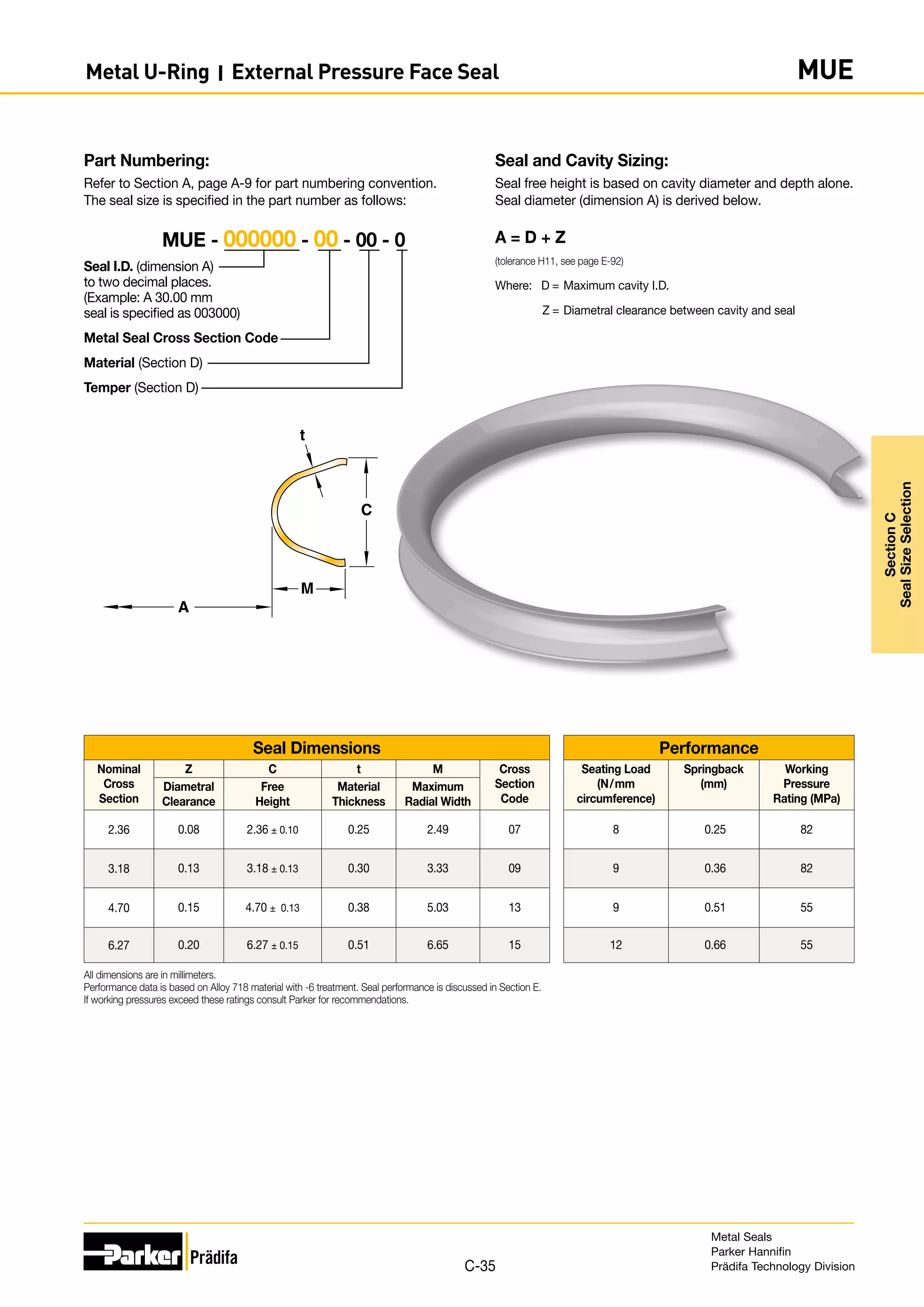
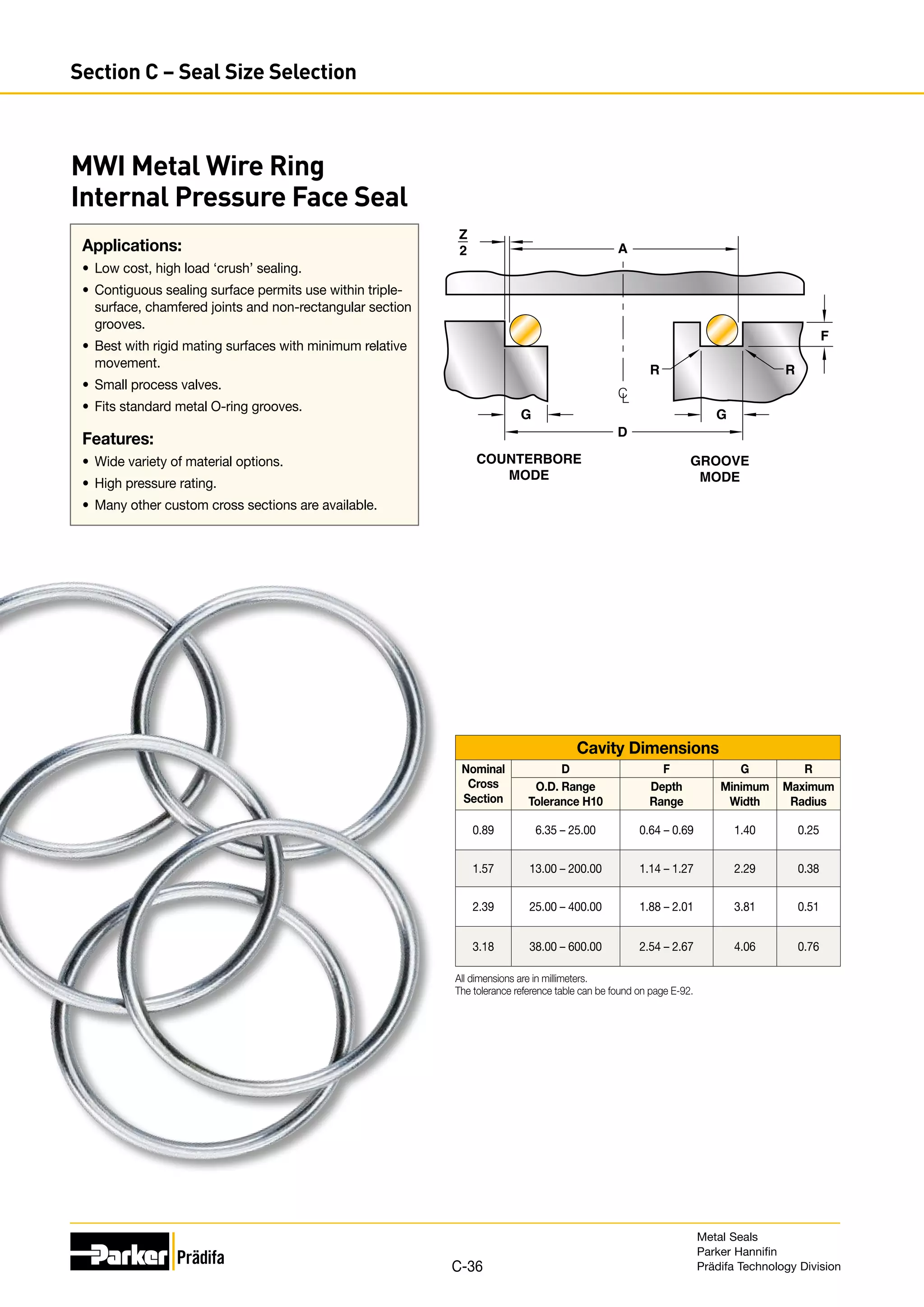
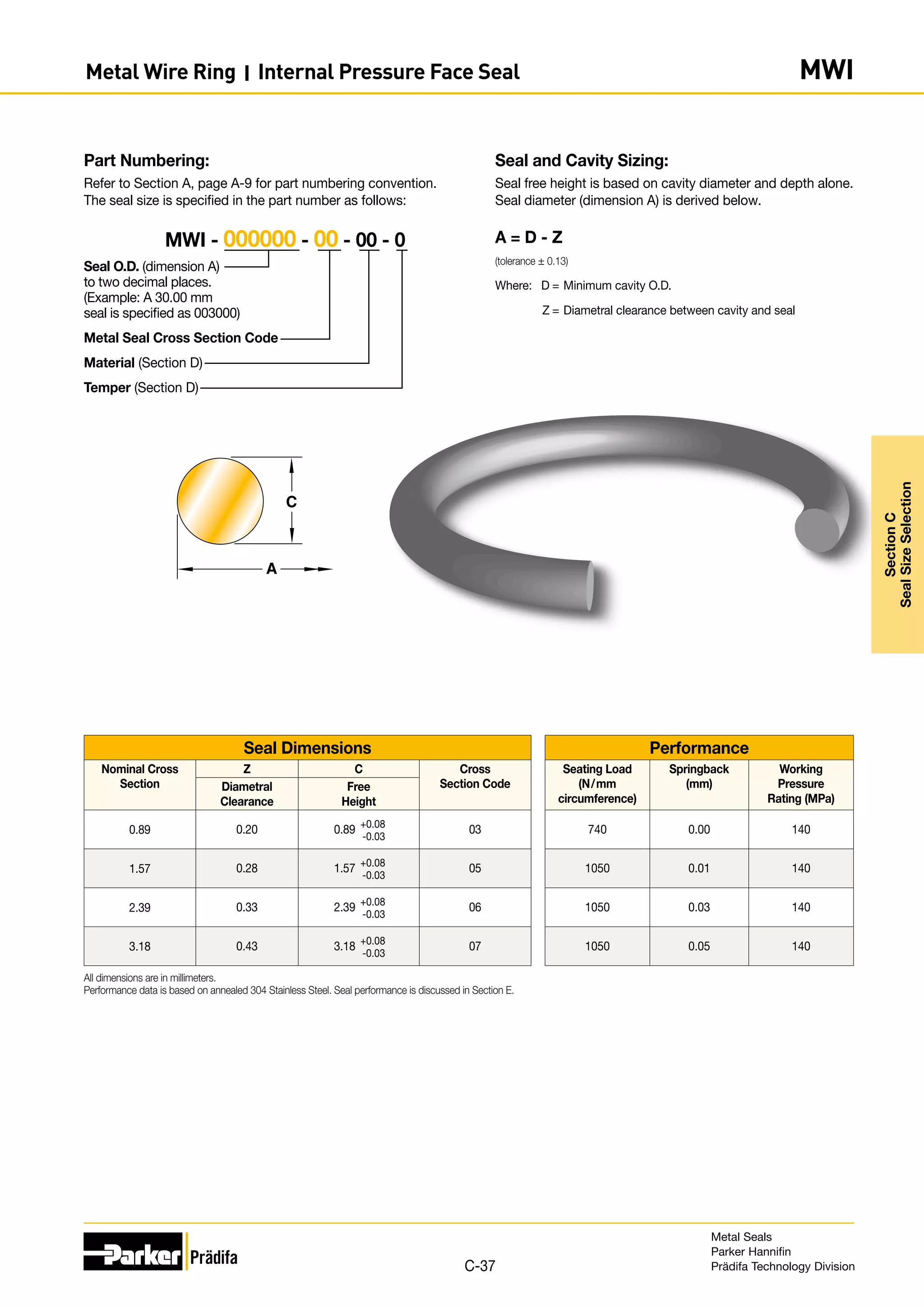
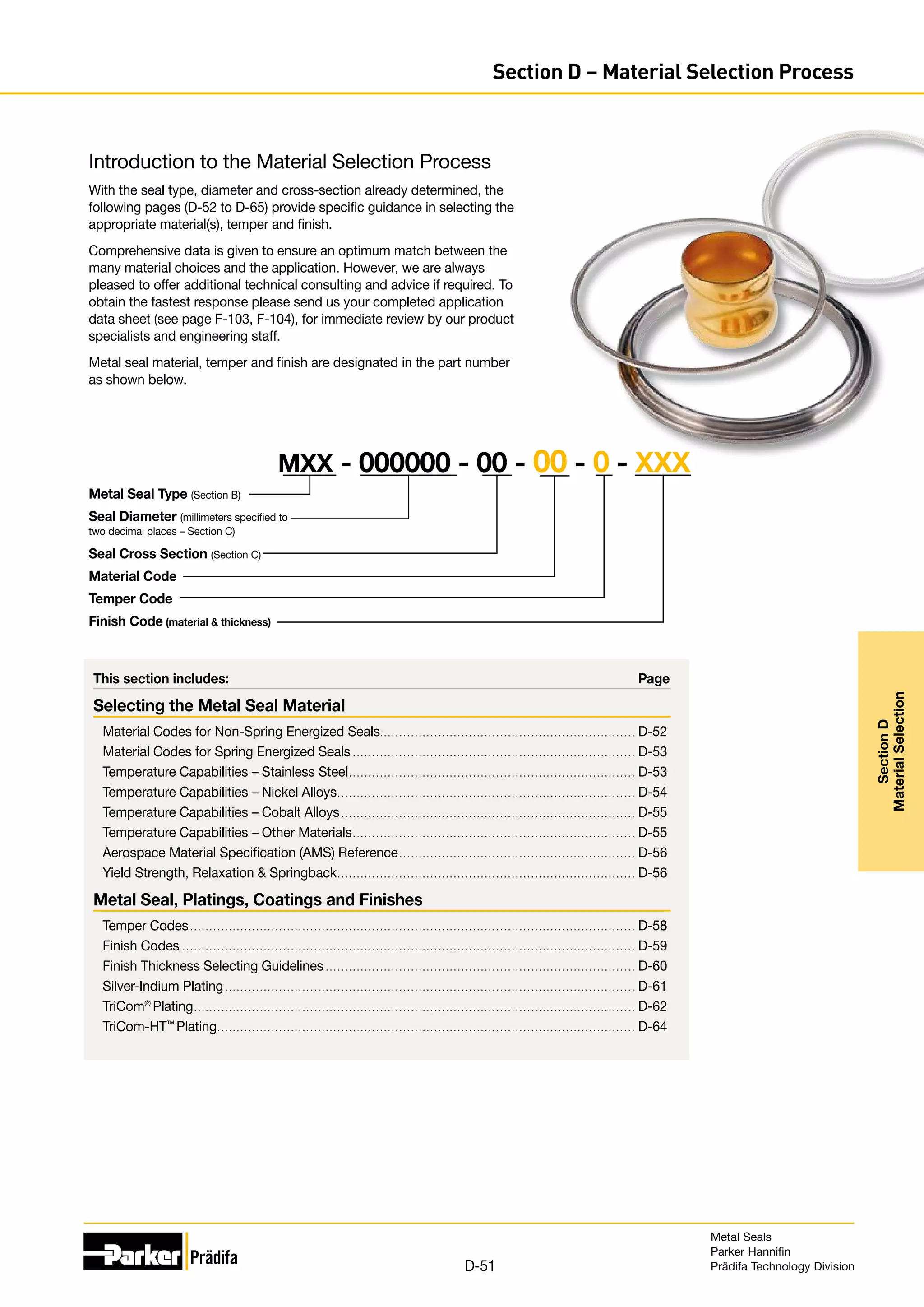
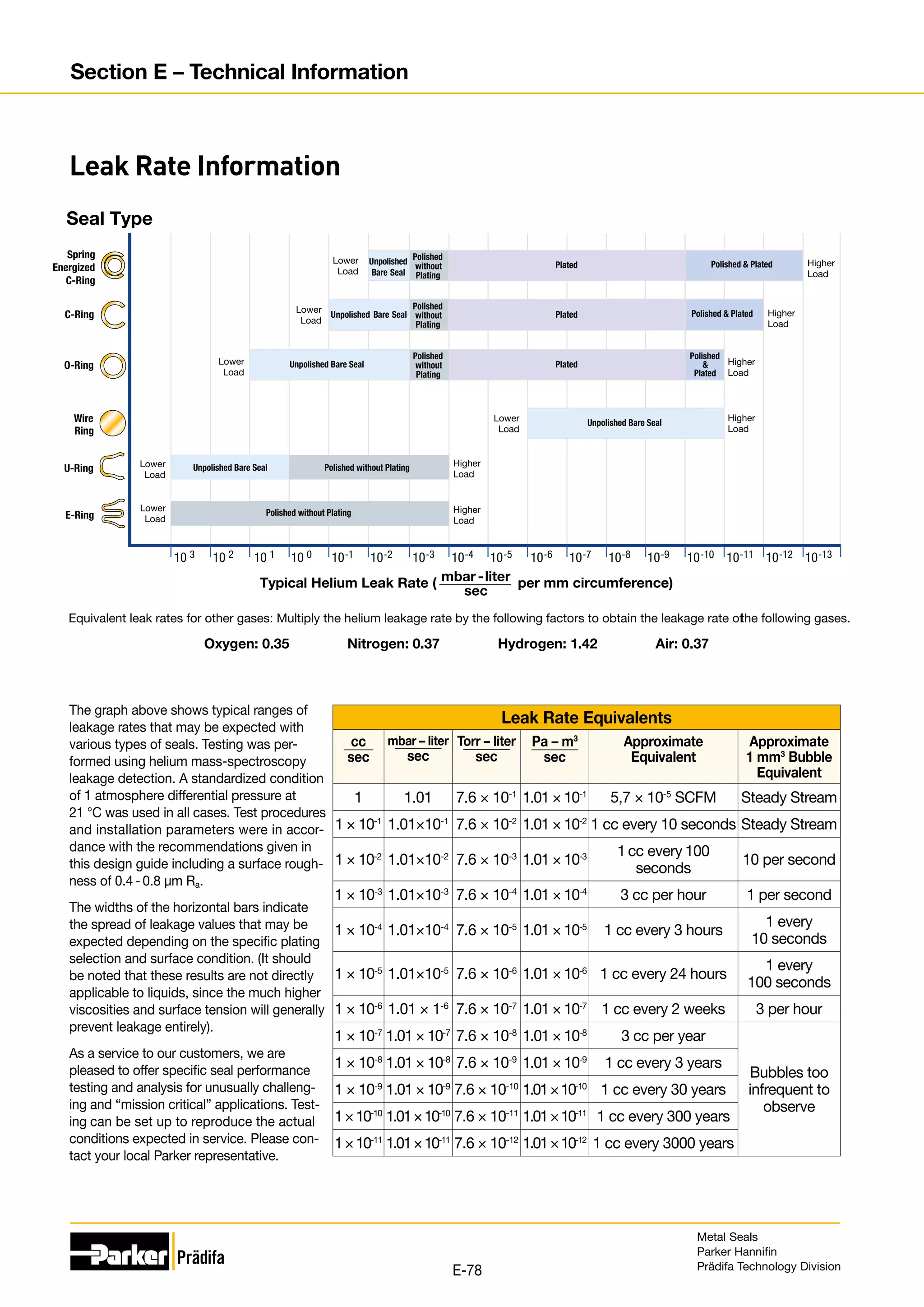
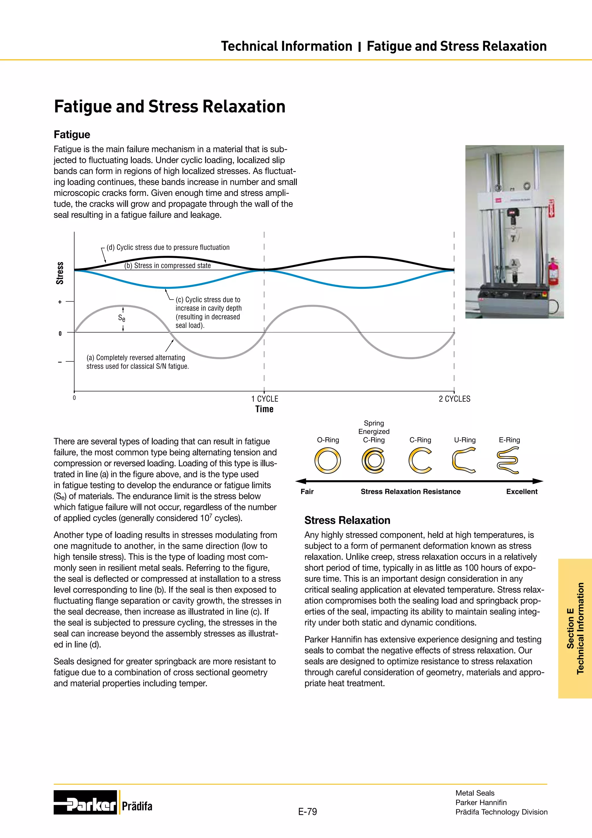
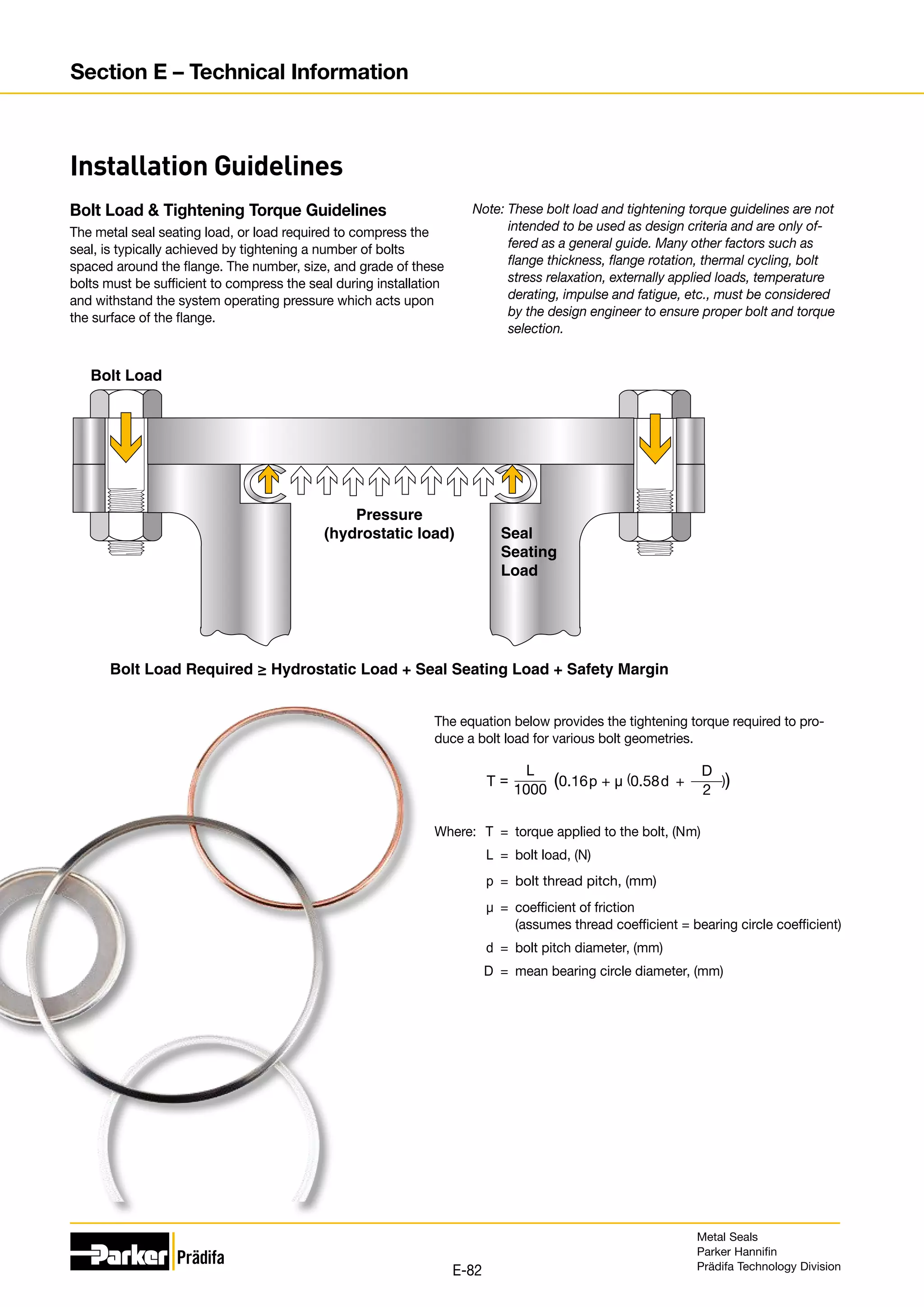
The document provides information on metal seals, including their advantages, applications, and design guidelines. It details the different types of metal seals, sizes, materials, and technical specifications. The document is intended to help users select the appropriate metal seal for their application.


![Seal Dimensions Performance
Nominal
Cross
Section
Z C t Cross
Section
Code
Seating Load
(N/mm circ.)
Springback
(mm)
Working Pressure Rating (MPa)
Diametral
Clearance
Free
Height
Material
Thickness
Vented Non-Vented
304SS/
321SS
Alloy
X-750/
Alloy 718
304SS/
321SS
Alloy
X-750/
Alloy 718
304SS/
321SS
Alloy
X-750/
Alloy 718
304SS/
321SS
Alloy
X-750/
Alloy 718
0.89 0.18 0.89
+0.08
-0.03
0.15 01 70 96 0.01 0.01 70 100 5 7
1.19 0.20 1.19
+0.08
-0.03
0.18 29 70 96 0.03 0.03 50 70 5 7
1.57 0.20 1.57 +0.08
-0.03
0.15 02 45 61 0.04 0.05 30 45 4 6
0.25 03 96 130 0.03 0.04 75 110 5 7
0.30 31 140 190 0.03 0.03 100 140 5 8
0.35 08 190 260 0.03 0.03 120 170 6 8
2.39 0.23 2.39 +0.08
-0.03
0.15 04 26 35 0.05 0.05 10 15 5 7
0.25 05 52 70 0.05 0.05 30 40 6 8
0.30 32 70 96 0.03 0.04 40 70 6 8
0.46 09 210 280 0.03 0.04 110 170 6 9
3.18 0.28 3.18 +0.08
-0.03
0.20 06 17 24 0.10 0.13 15 30 3 5
0.25 07 26 35 0.08 0.10 30 40 3 5
0.30 25 49 70 0.05 0.08 40 70 4 6
0.51 10 160 210 0.05 0.05 110 170 5 7
3.96 0.33 3.96 +0.10
-0.00
0.41 11 70 96 0.10 0.13 30 40 5 7
0.51 12 130 175 0.08 0.10 90 140 5 8
4.78 0.35 4.78 +0.13
-0.00
0.51 13 78 105 0.10 0.13 30 40 5 7
0.63 14 120 170 0.08 0.10 100 150 5 8
6.35 0.46 6.35 +0.13
-0.00
0.63 15 78 105 0.13 0.15 30 40 5 7
0.81 16 170 230 0.10 0.13 90 140 5 8
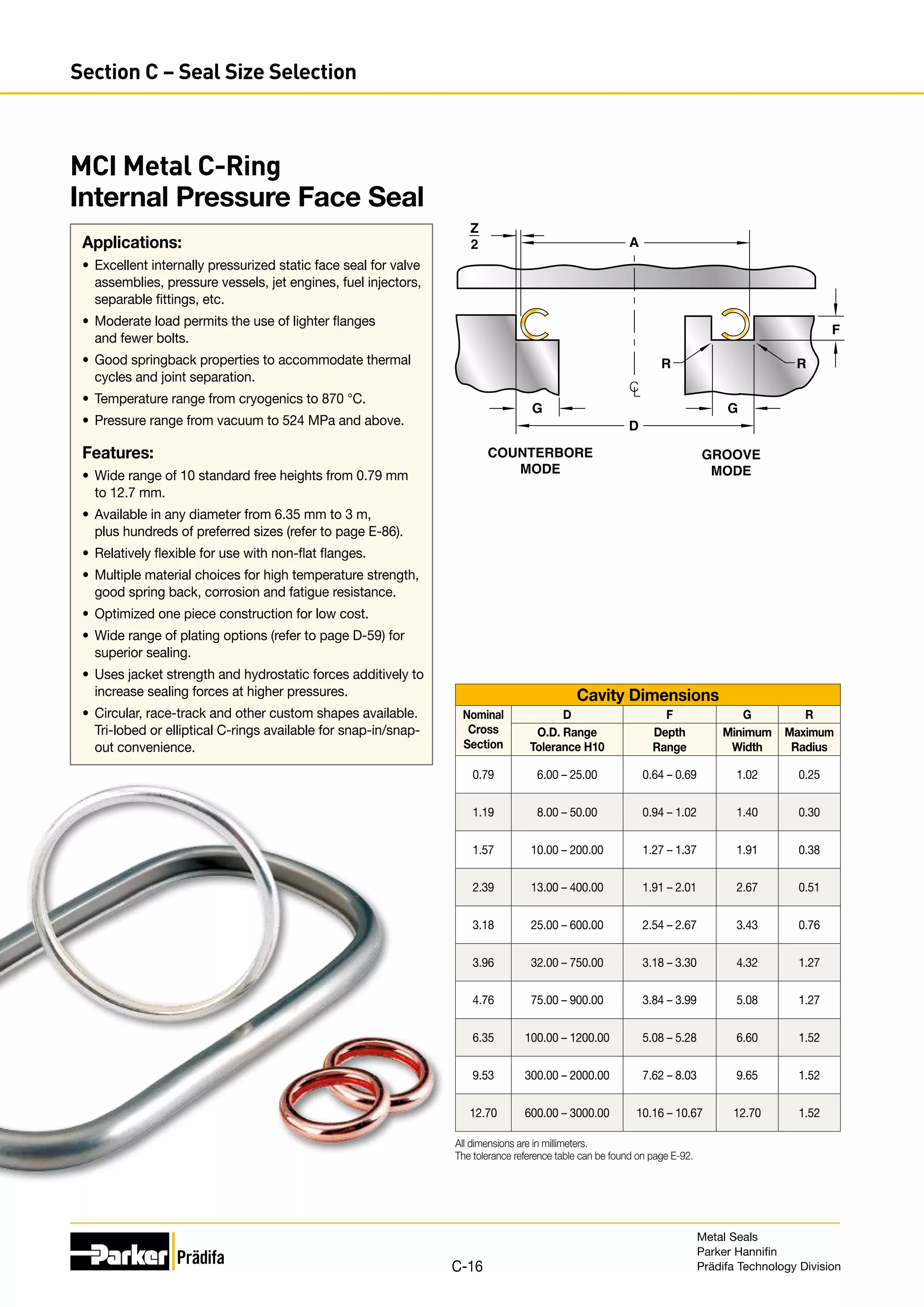
All dimensions are in millimeters and prior to plating.
Performance data is based on Alloy 718 material with -6 treatment. Seal performance is discussed in Section E.
If working pressures exceed these ratings consult Parker for recommendations.
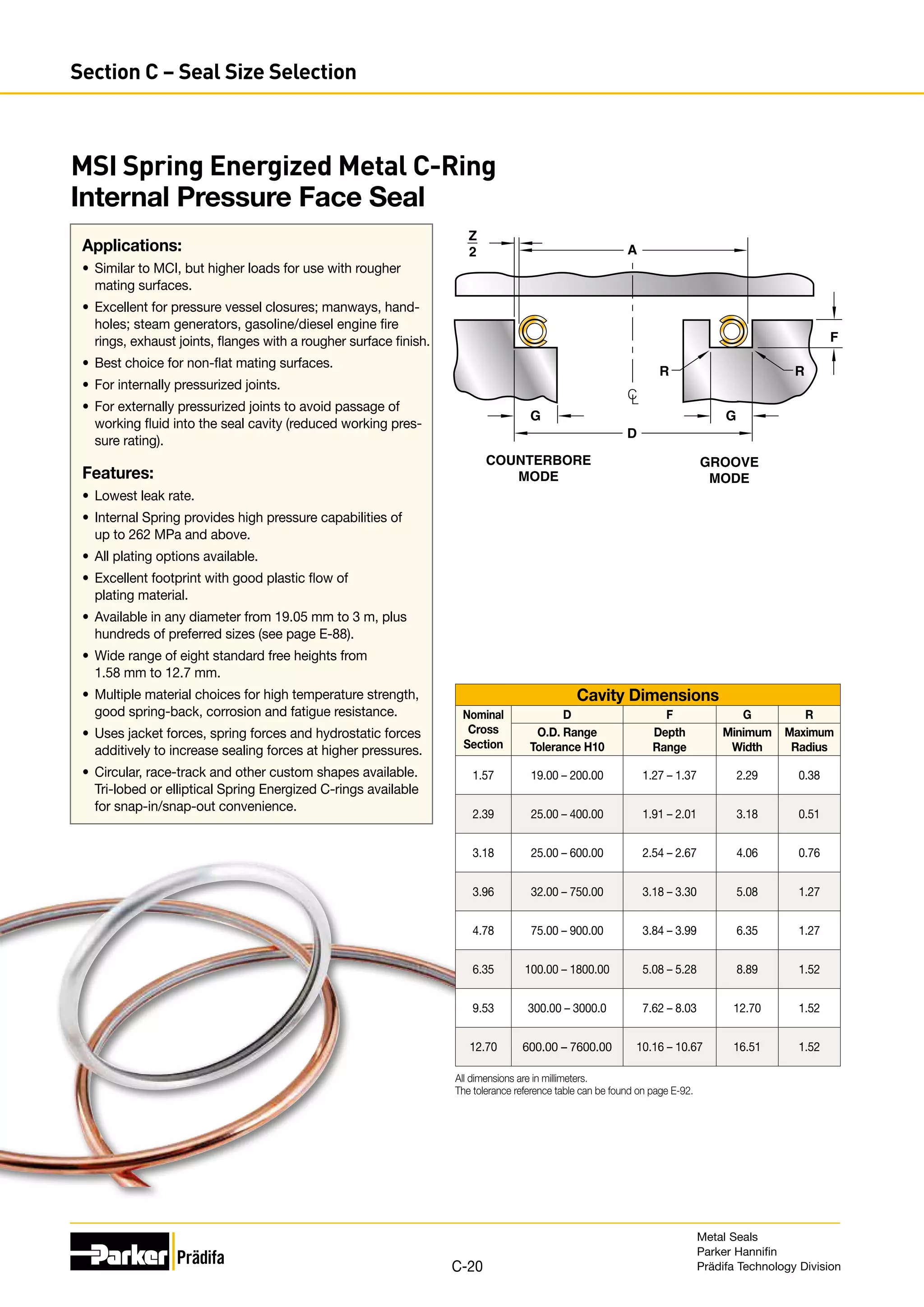
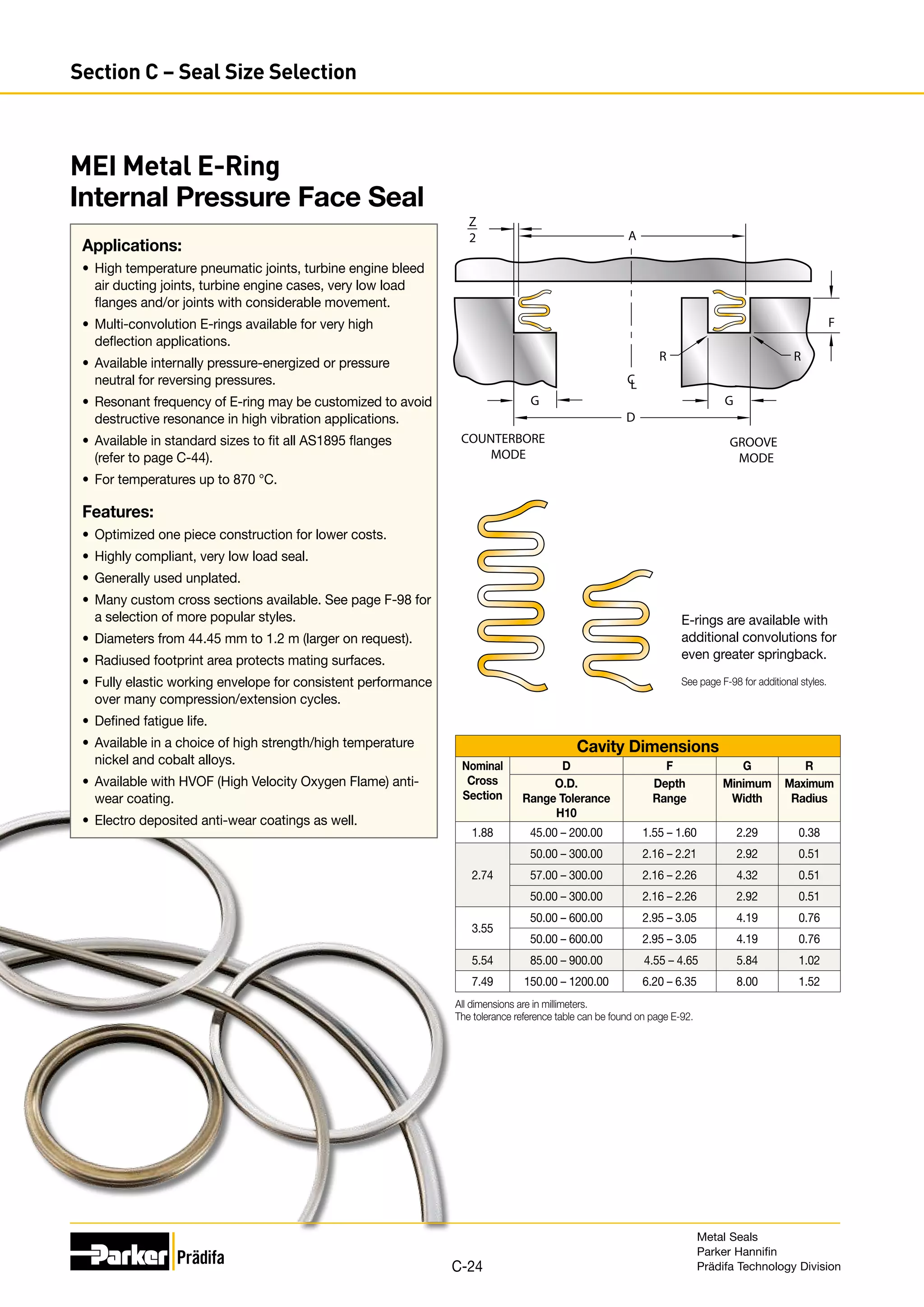
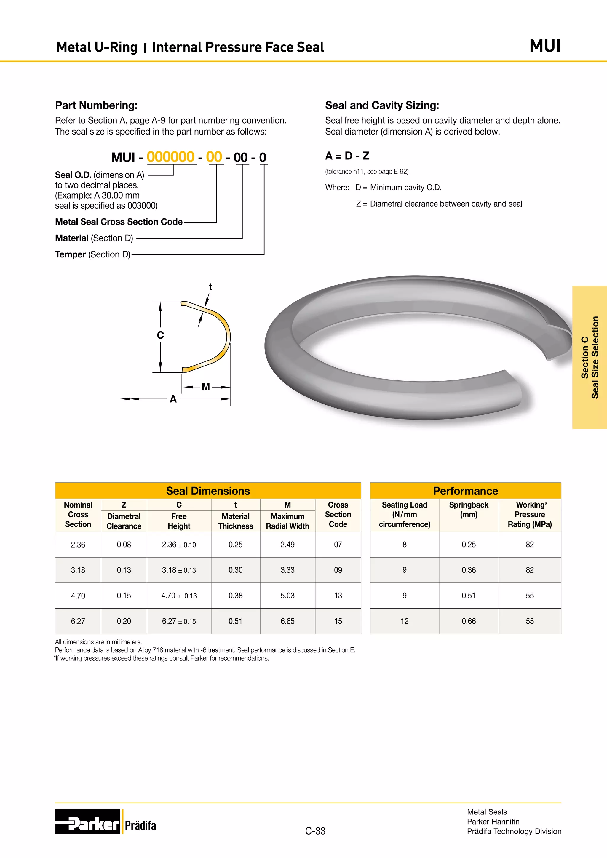
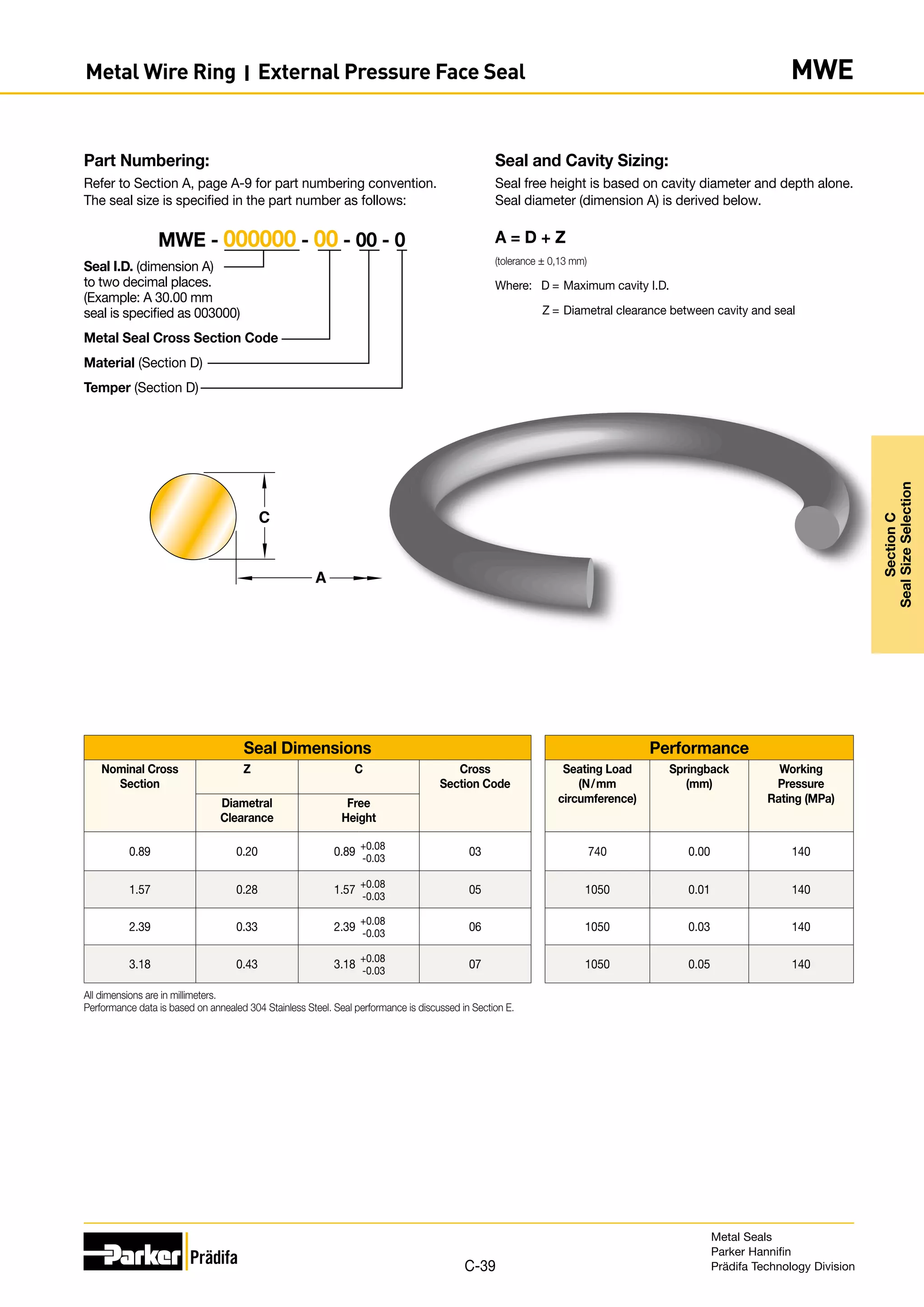
Seal and Cavity Sizing:
Seal free height is based on cavity diameter and depth alone.
Seal diameter (dimension A) is derived below.
Seal Tolerance
Free Height Seal Diameter Tolerance (-0.000)
0.89 - 4.77 +0.13
6.35 +0.20
9.52 - 15.87 +0.25
A = D - Z - 2Pmax
Where: D = Minimum cavity O.D.
Z = Diametral clearance between cavity and seal
Pmax = Maximum plating thickness (from page D-60)
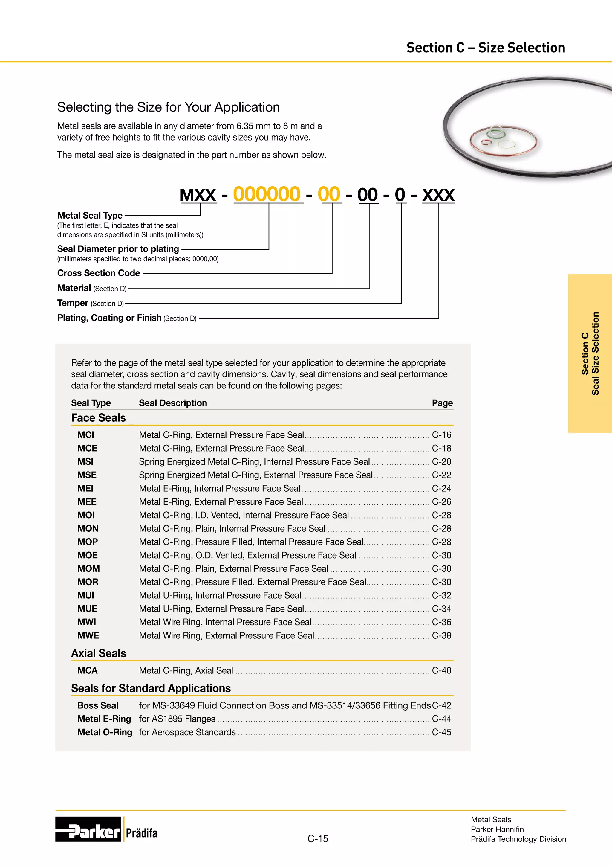
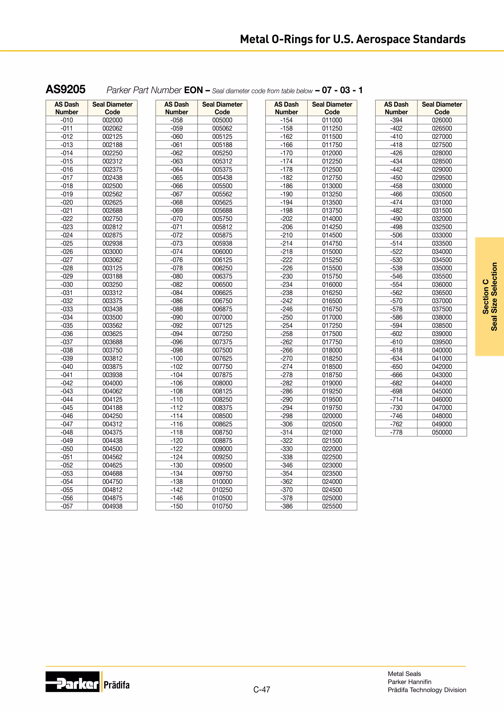
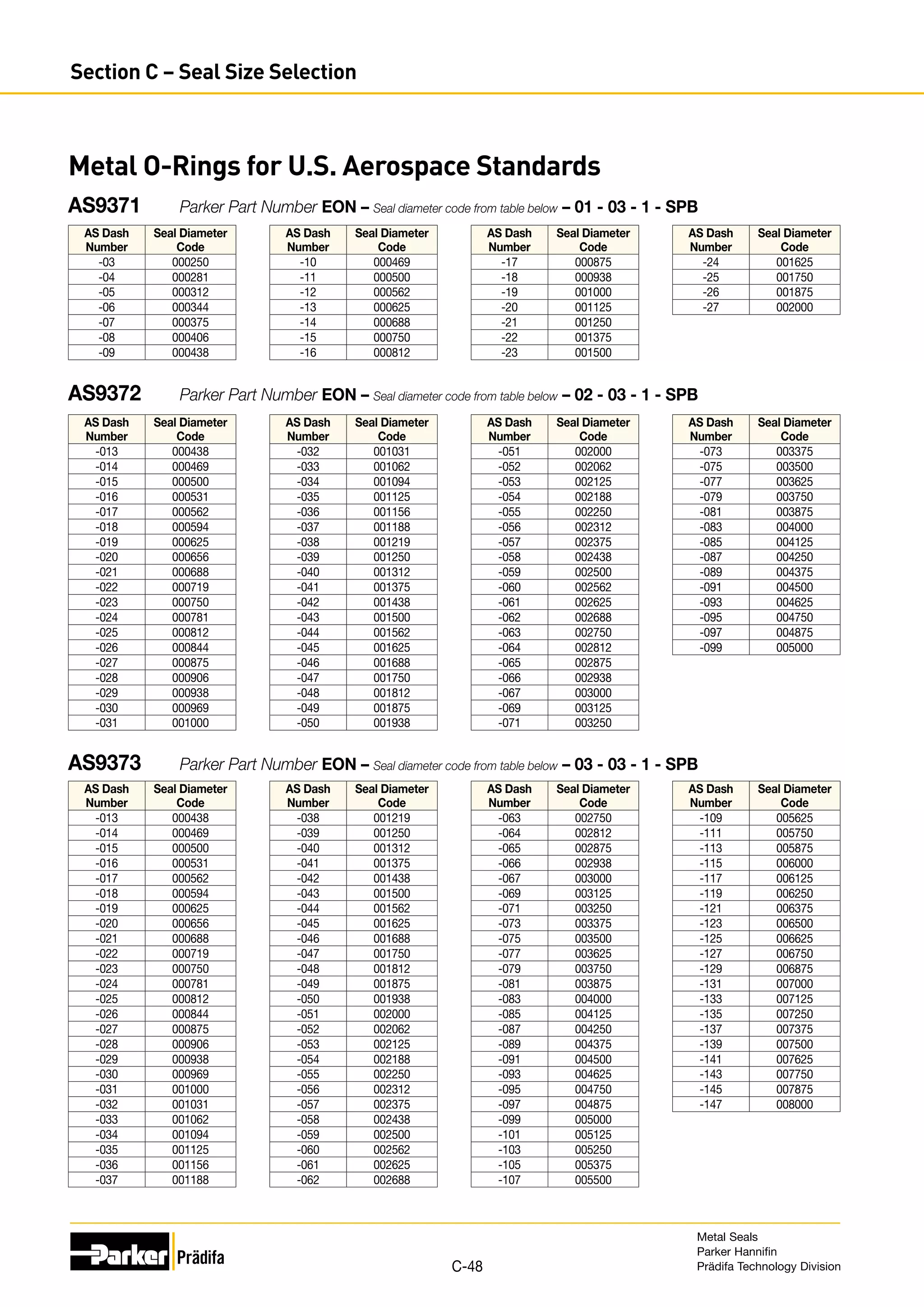
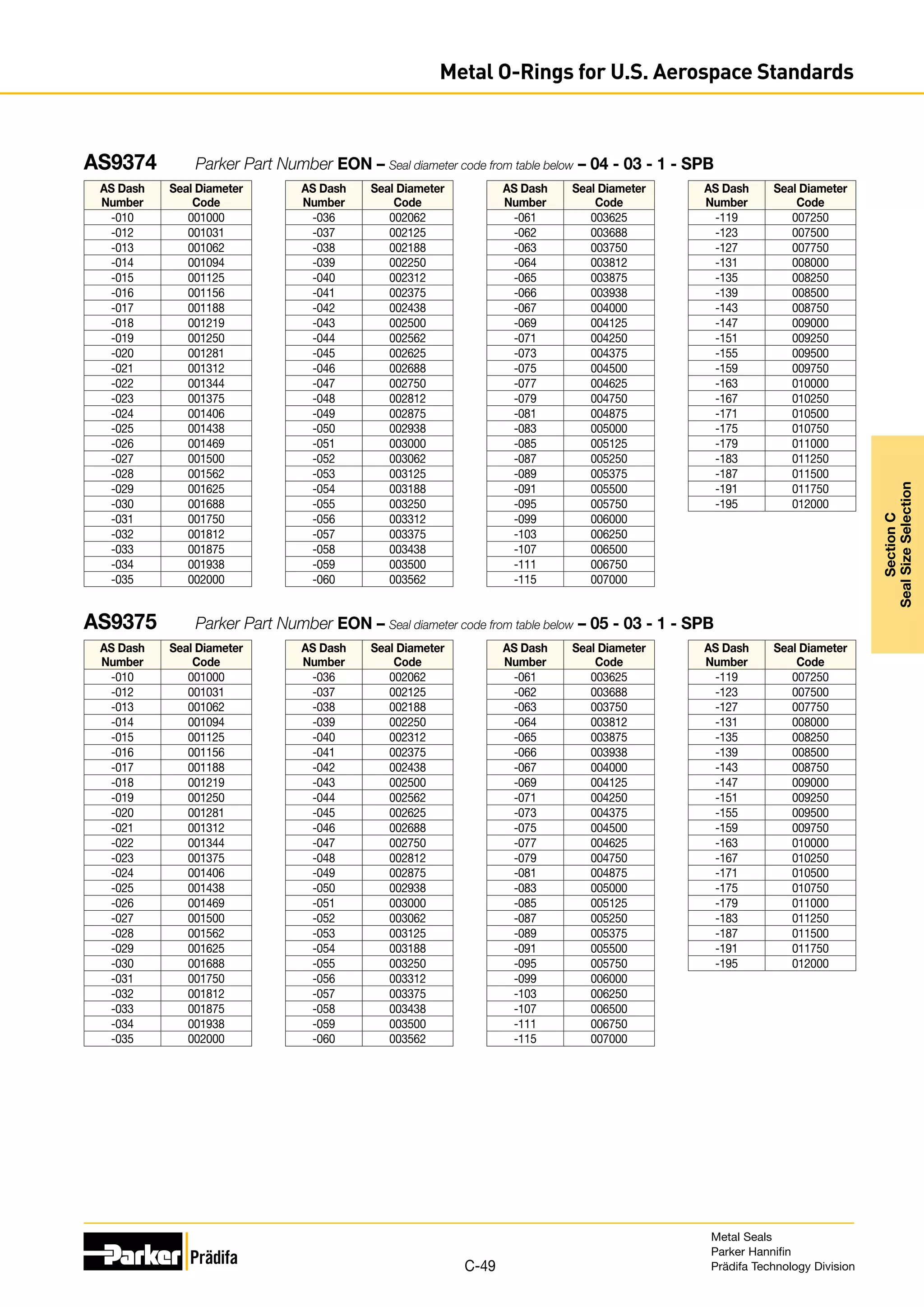
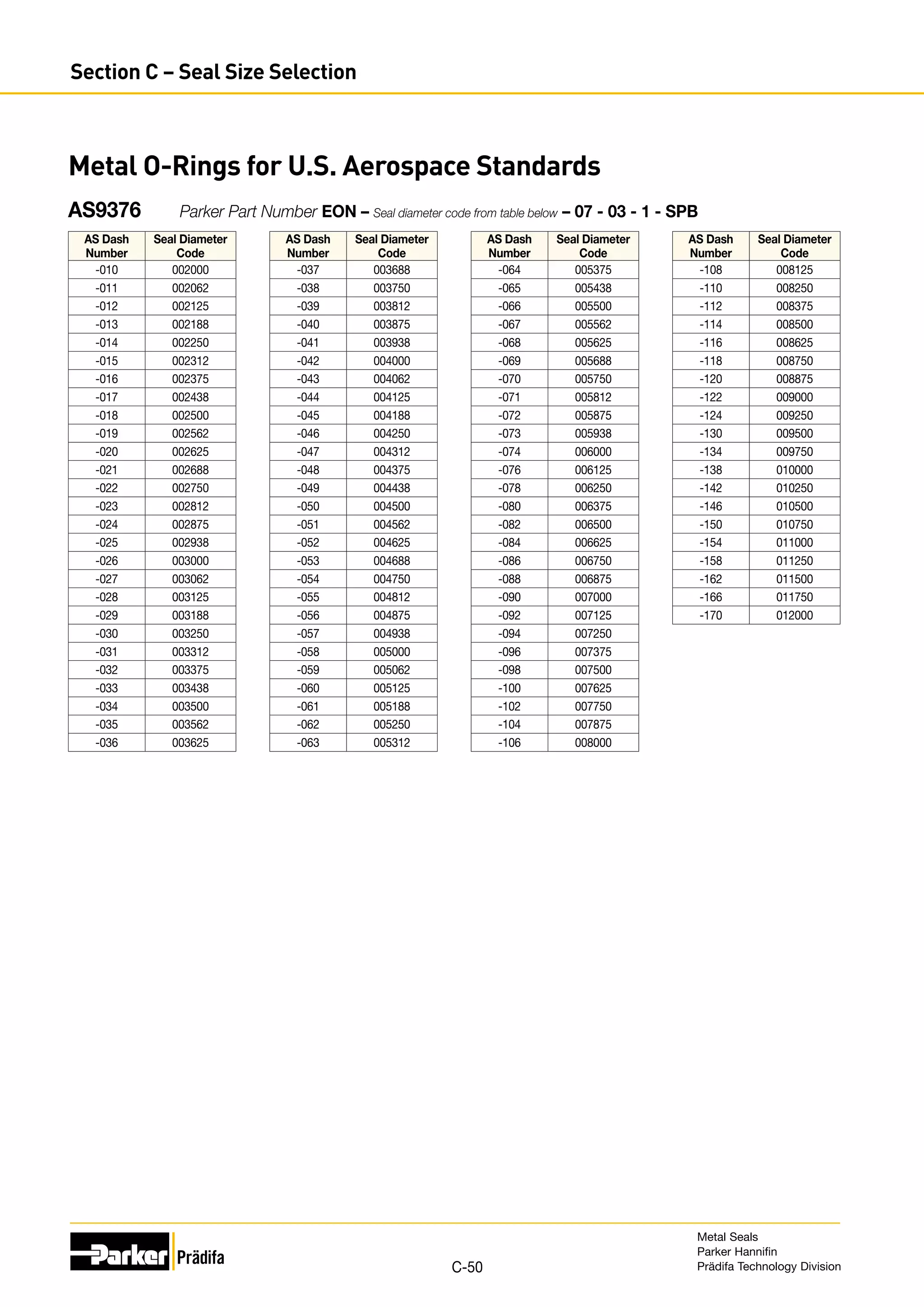
Part Numbering:
Refer to Section A, page A-9 for part numbering convention.
The seal size is specified in the part number as follows:
Seal O.D. prior to plating
(dimension A) to two decimal
places. (Example: A 30.00 mm
seal is specified as 003000)
Metal Seal Cross Section Code
Material (Section D)
Temper (Section D)
Plating, Coating or Finish (Section D)
MO [I, N, P] - 000000 - 00 - 00 - 0 - XXX
t
A
C
Metal Seals
Parker Hannifin
Prädifa Technology Division
C-29
Section
C
Seal
Size
Selection
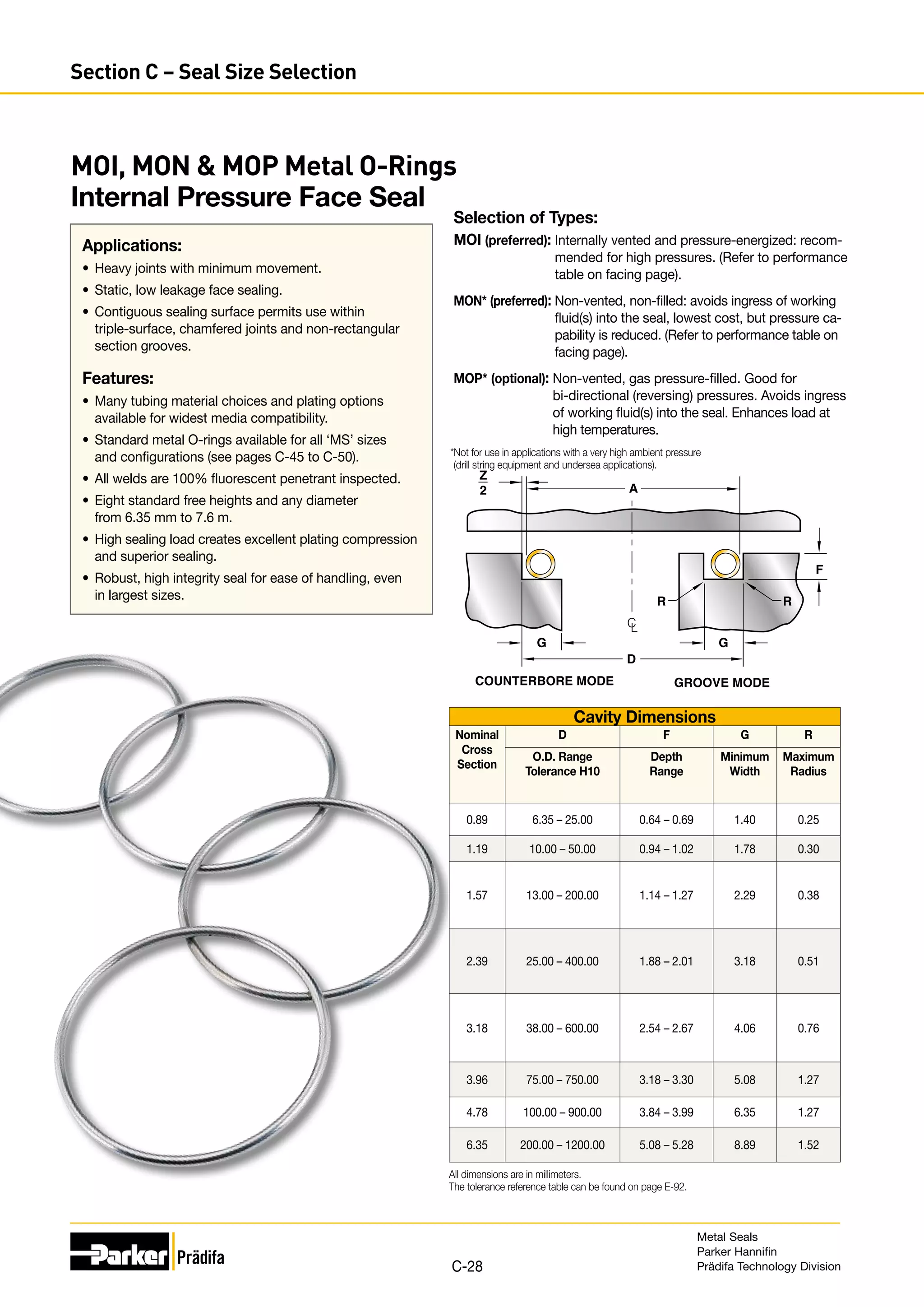
Metal O-Rings I Internal Pressure Face Seal MOI, MON MOP](https://image.slidesharecdn.com/metalsealdesignguidemetricparker-220122070824/75/Metal-seal-design-guide-metric-Parker-29-2048.jpg)
![Seal Dimensions Performance
Nominal
Cross
Section
Z C t Cross
Section
Code
Seating Load
(N/mm circ.)
Springback
(mm)
Working Pressure Rating (MPa)
Diametral
Clearance
Free
Height
Material
Thickness
Vented Non-Vented
304SS/
321SS
Alloy
X-750/
Alloy 718
304SS/
321SS
Alloy
X-750/
Alloy 718
304SS/
321SS
Alloy
X-750/
Alloy 718
304SS/
321SS
Alloy
X-750/
Alloy 718
0.89 0.18 0.89
+0.08
-0.03
0.15 01 70 96 0.01 0.01 70 100 5 7
1.19 0.20 1.19
+0.08
-0.03
0.18 29 70 96 0.03 0.03 50 70 5 7
1.57 0.20 1.57 +0.08
-0.03
0.15 02 45 61 0.04 0.05 30 45 4 6
0.25 03 96 130 0.03 0.04 75 110 5 7
0.30 31 140 190 0.03 0.03 100 140 5 8
0.35 08 190 260 0.03 0.03 120 170 6 8
2.39 0.23 2.39 +0.08
-0.03
0.15 04 26 35 0.05 0.05 10 15 5 7
0.25 05 52 70 0.05 0.05 30 40 6 8
0.30 32 70 96 0.03 0.04 40 70 6 8
0.46 09 210 280 0.03 0.04 110 170 6 9
3.18 0.28 3.18 +0.08
-0.03
0.20 06 17 24 0.10 0.13 15 30 3 5
0.25 07 26 35 0.08 0.10 30 40 3 5
0.30 25 49 70 0.05 0.08 40 70 4 6
0.51 10 160 210 0.05 0.05 110 170 5 7
3.96 0.33 3.96 +0.10
-0.00
0.41 11 70 96 0.10 0.13 30 40 5 7
0.51 12 130 175 0.08 0.10 90 140 5 8
4.78 0.35 4.78 +0.13
-0.00
0.51 13 78 105 0.10 0.13 30 40 5 7
0.63 14 120 170 0.08 0.10 100 150 5 8
6.35 0.46 6.35 +0.13
-0.00
0.63 15 78 105 0.13 0.15 30 40 5 7
0.81 16 170 230 0.10 0.13 90 140 5 8
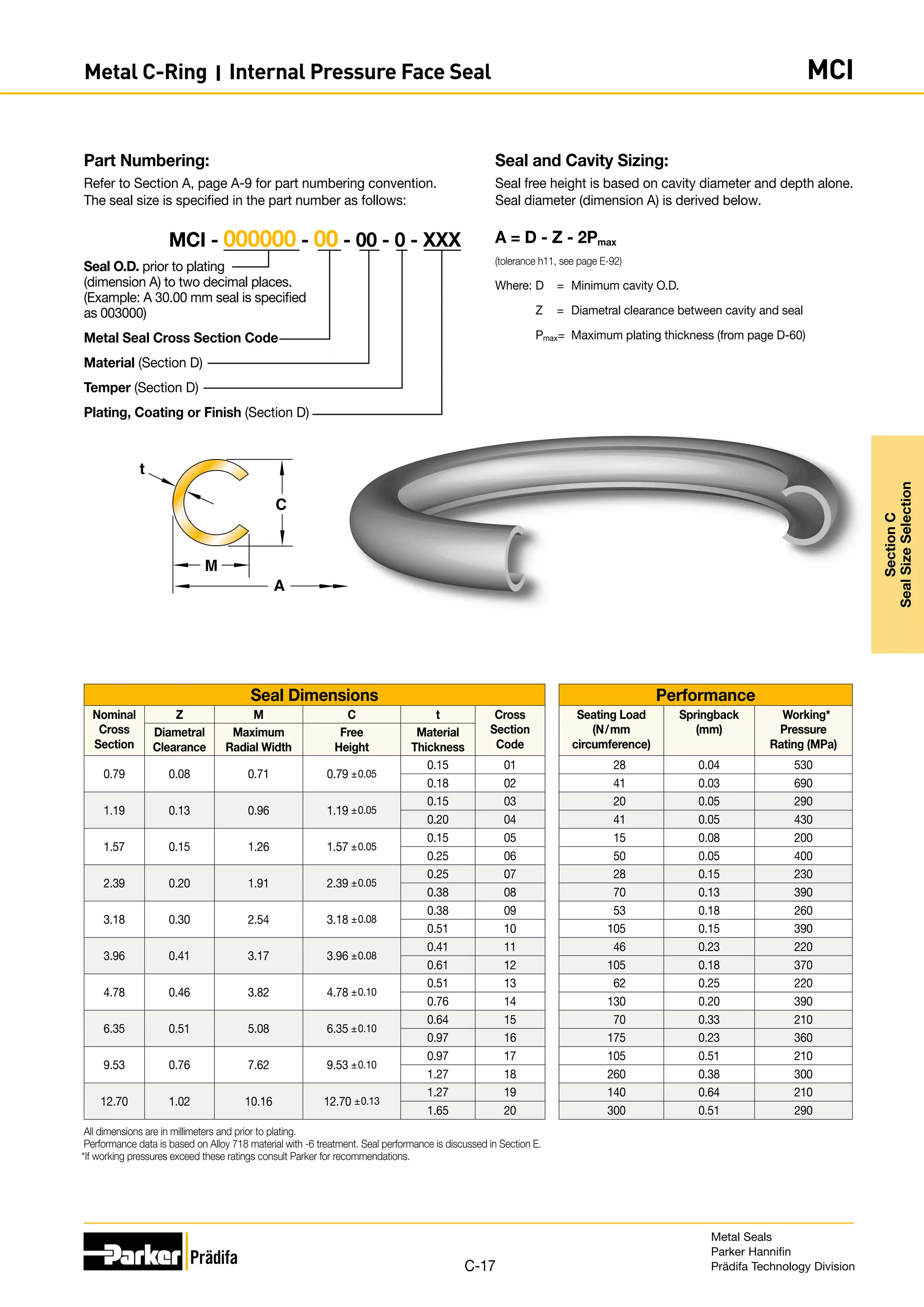
All dimensions are in millimeters and prior to plating.
Performance data is based on Alloy 718 material with -6 treatment. Seal performance is discussed in Section E.
If working pressures exceed these ratings consult Parker for recommendations.
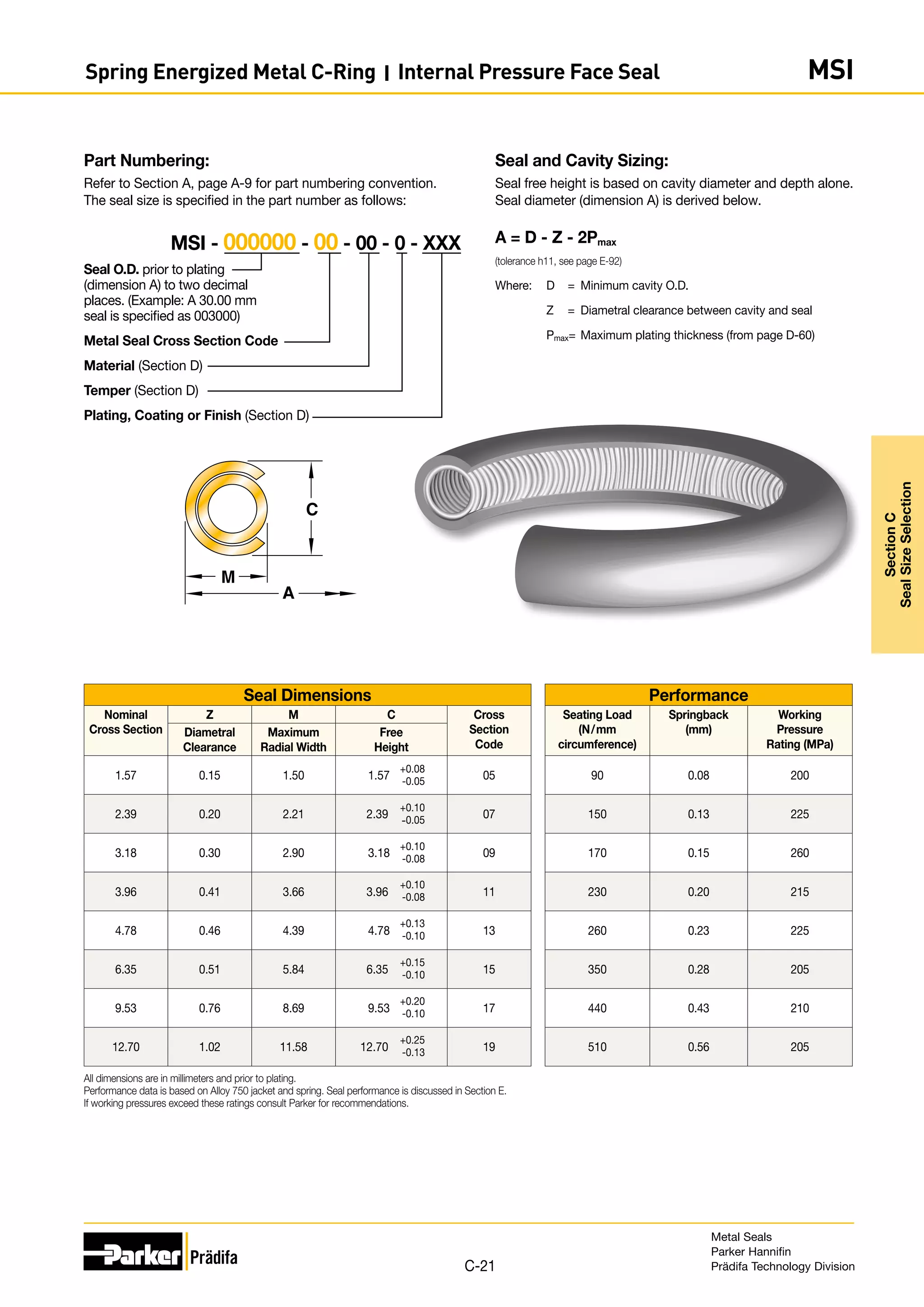
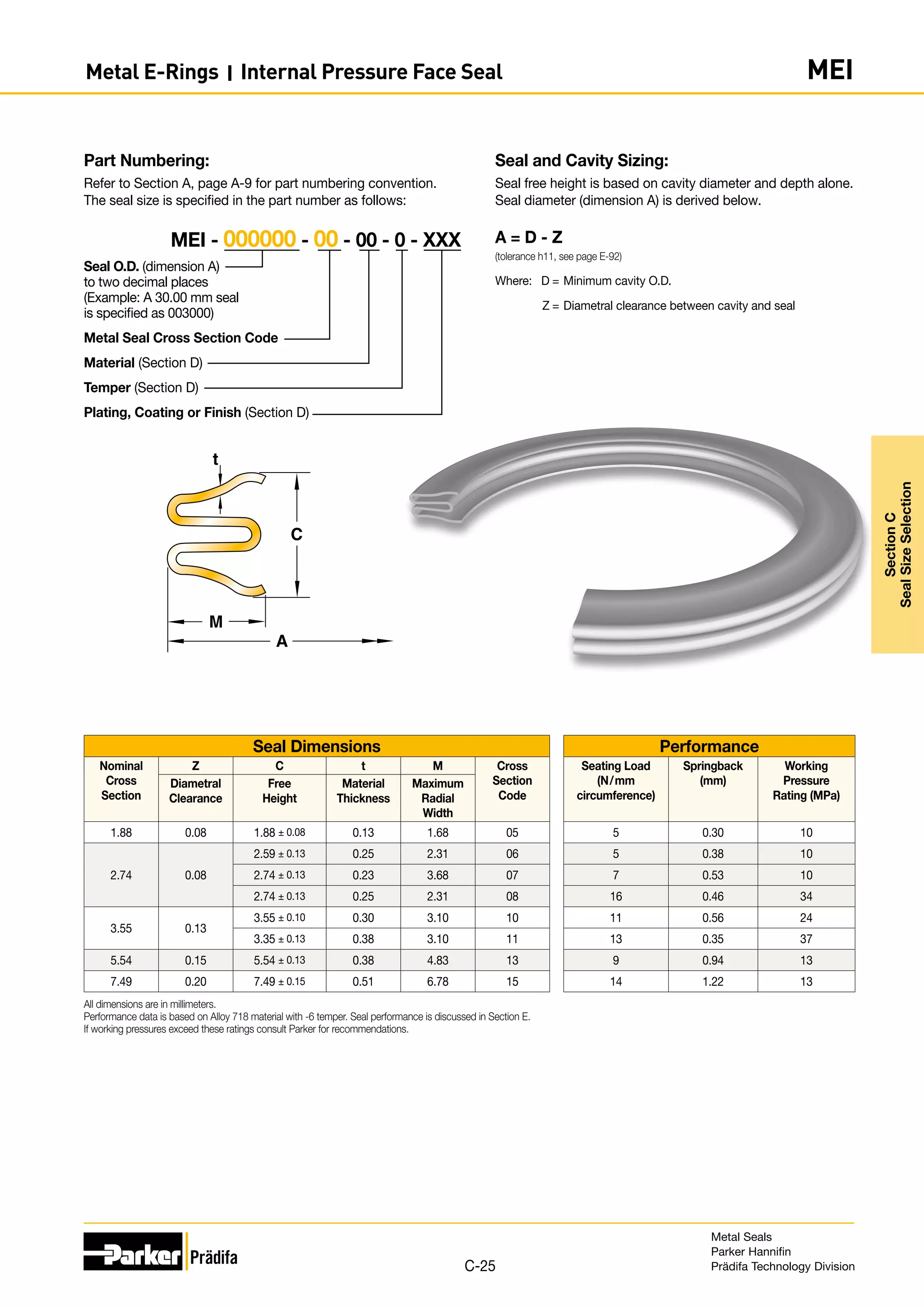
Seal and Cavity Sizing:
Seal free height is based on cavity diameter and depth alone.
Seal diameter (dimension A) is derived below.
Seal Tolerance
Free Height Seal Diameter Tolerance (-0.000)
0.89 - 4.77 +0.13
6.35 +0.20
9.52 - 15.87 +0.25
A = D + Z + 2Pmax
Where: D = Maximum cavity I.D.
Z = Diametral clearance between cavity and seal
Pmax = Maximum plating thickness (from page D-60)
Part Numbering:
Refer to Section A, page A-9 for part numbering convention.
The seal size is specified in the part number as follows:
Seal I.D. prior to plating
(dimension A) to two decimal
places. (Example: A 30.00 mm
seal is specified as 003000)
Metal Seal Cross Section Code
Material (Section D)
Temper (Section D)
Plating, Coating or Finish (Section D)
MO [E, M, R] - 000000 - 00 - 00 - 0 - XXX
t
A
C
Metal Seals
Parker Hannifin
Prädifa Technology Division
C-31
Section
C
Seal
Size
Selection
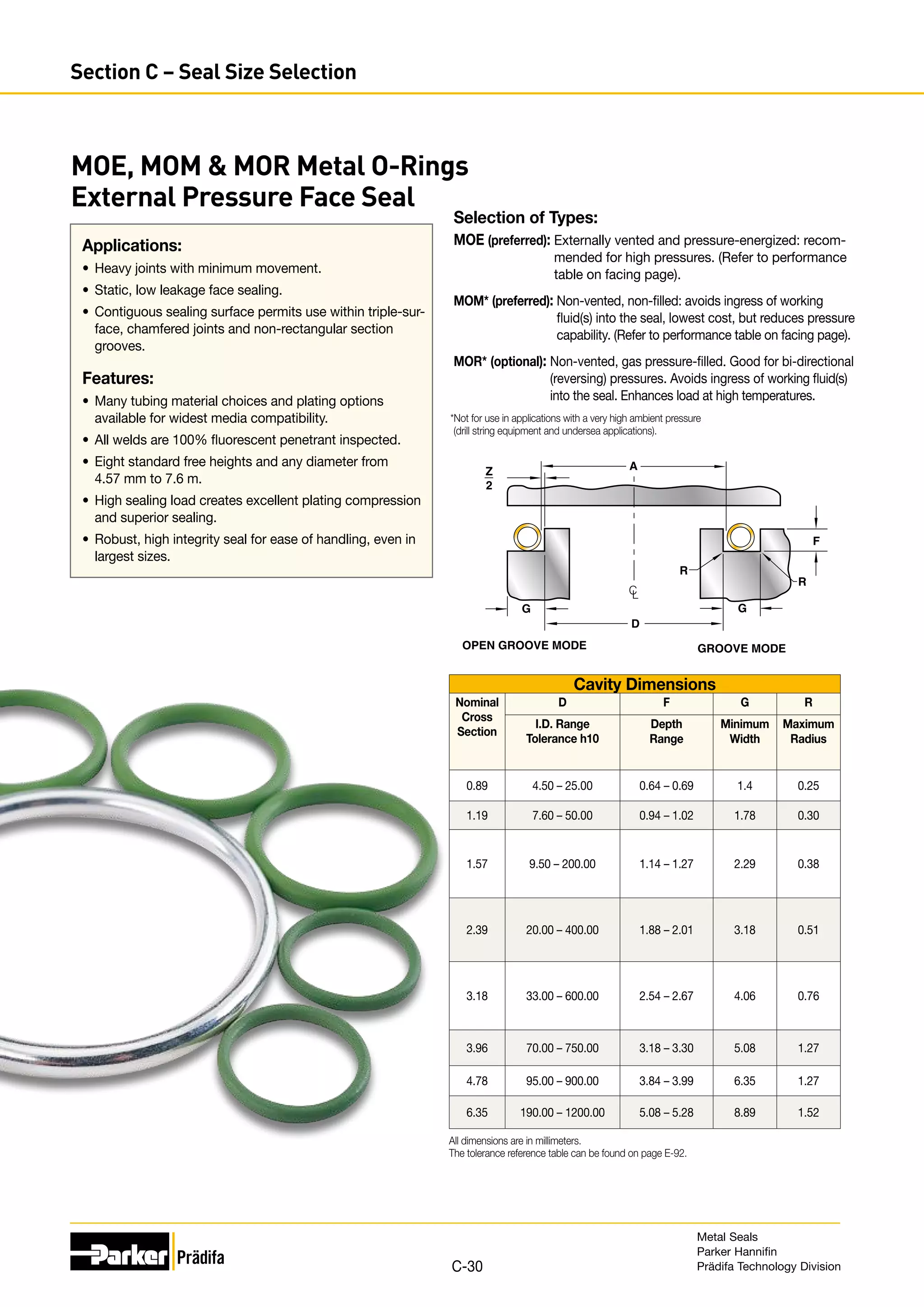
Metal O-Rings I External Pressure Face Seal MOE, MOM MOR](https://image.slidesharecdn.com/metalsealdesignguidemetricparker-220122070824/75/Metal-seal-design-guide-metric-Parker-31-2048.jpg)

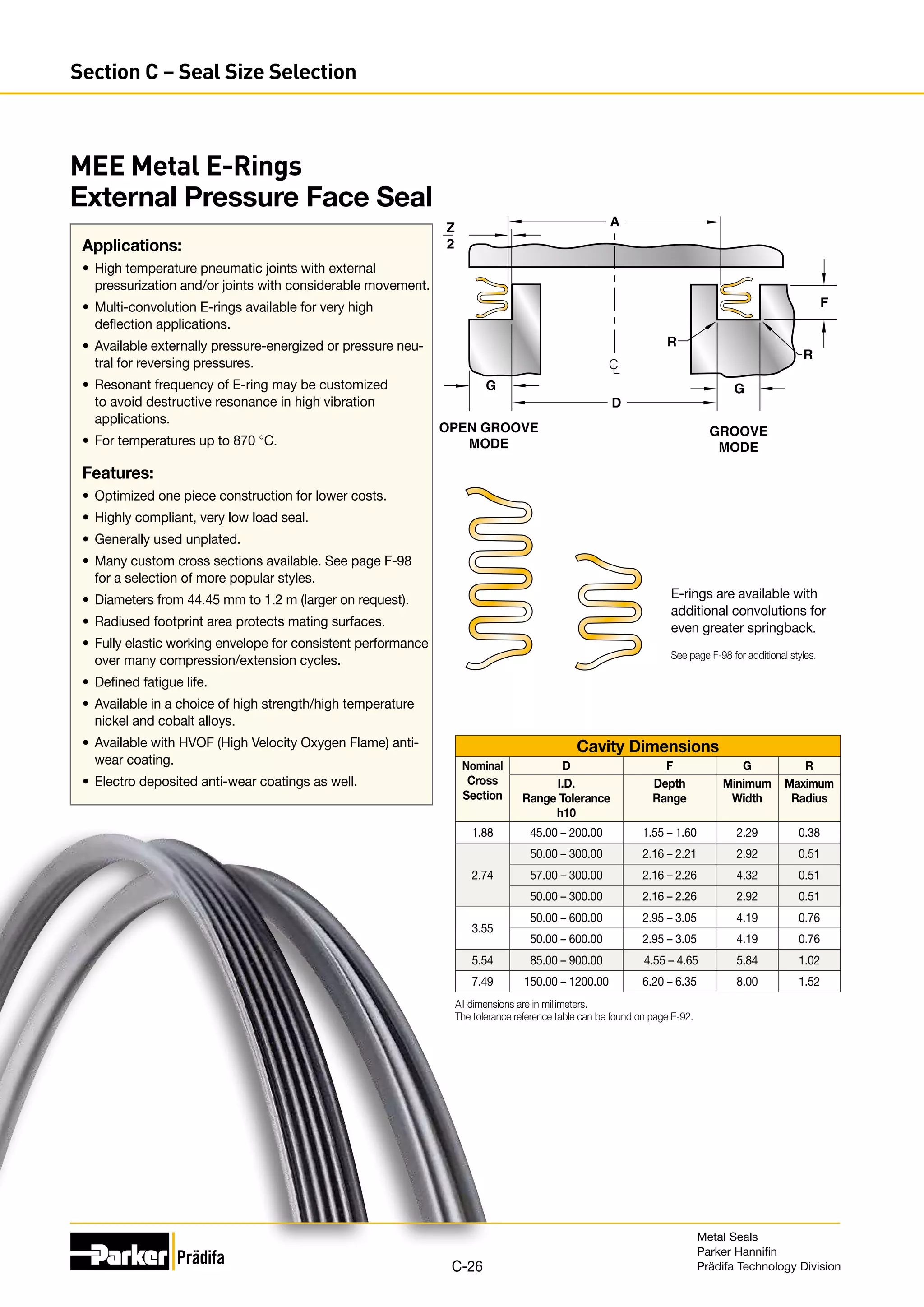
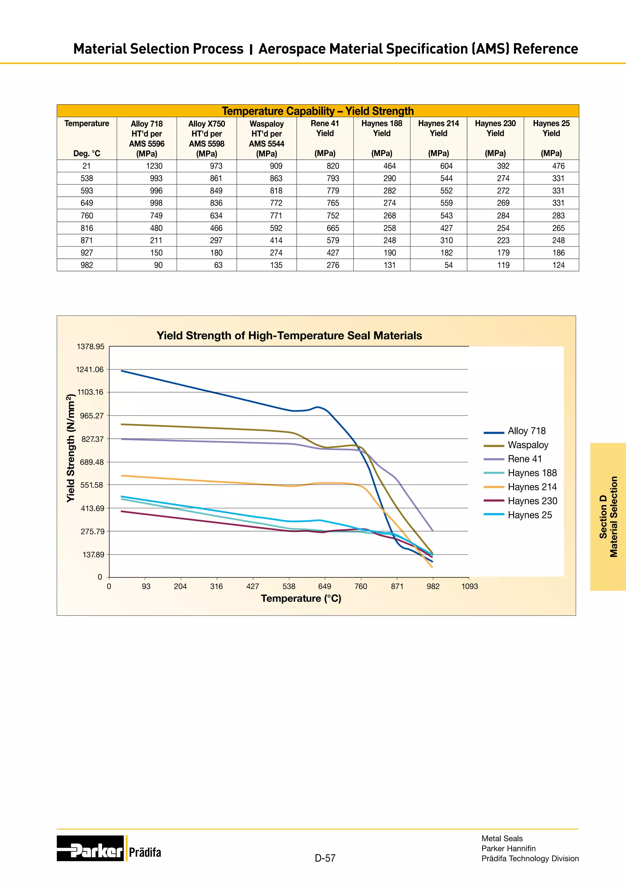
![Temperature Capability [cont.]
Cobalt Alloys
Material UNS
No.
AMS Specifications Description Maximum
Recommend-
ed Service
Temperature
Typical Usage
Strip
Sheet
Tub-
ing
Wire
Wire
Rings
Spring
Elgiloy®
Cobalt-
Chromium-
Nickel Alloy
R30003 AMS 5876 AMS 5833
This cobalt-chromium-nickel alloy gives a
combination of high strength, ductility and good
mechanical properties and is age hardenable.
Excellent fatigue life and corrosion resistance in
numerous environments.
371 °C
(700 °F)
Approved high
strength spring
material for sour
gas application.
Haynes®
25
R30605 AMS 5537
A solid-solution-strengthened, cobalt-nickel-
chromium-tungsten alloy with very good resistance to
high-temperature oxidizing environments. Largely
replaced by Haynes 188 and Haynes 230.
871 °C
(1600 °F)
High temperature
C-ring applications.
High wear C-ring
applications.
Haynes®
188
R30188 AMS 5608
A cobalt-nickel-chromium-tungsten alloy with very
good resistance to high-temperature oxidizing
environments. Better thermal stability than Haynes 25
with similar high-temperature strength.
871 °C
(1600 °F)
High temperature
C-ring applications.
Temperature Capabilities
Other Materials
Material UNS
No.
AMS Specifications Description Maximum
Recommended
Service
Temperature
Typical Usage
Strip
Sheet
Tub-
ing
Wire
Wire
Rings
Spring
Indium N/A
Commercially pure ( 99.9%)
Indium
66 °C
(150 °F)
Electroplated in various combinations to
provide aductile outer layer that enhances
seal-ability and/or corrosion. Occasionally
used for wire rings.
Lead N/A Commercially pure ( 99.9%) Lead
204 °C
(400 °F)
PTFE N/A
Chemically inert polymer.
Highly resistant to chemical attack.
260 °C
(500 °F)
Near net-shape electroplated anti-wear coatings.
Used to prolong seal life in applications with high
thermal, mechanical or vibrational movement.
Copper C11000
Commercially pure ( 99.0%
copper). Fair corrosion resistance.
316 °C
(600 °F)
Electroplated in various combinations to provide
aductile outer layer that enhances seal-ability and/
or corrosion. Occasionally used for wire rings.
Nickel 200 N02200
Commercially pure ( 99.9%)
Nickel
316 °C
(600 °F)
Low-temperature wire rings.
Aluminum
Alloy 1100
A91100
Commercially pure ( 99.0%)
aluminum. Good corrosion
resistance and high formability.
538 °C
(1000 °F)
Machined seals.
Silver N/A
Commercially pure ( 99.9%)
Silver
260 °C (500 °F)
Oxidizing;
650 °C (1200 °F)
non-oxydizing
Electroplated in various combinations to provide
aductile outer layer that enhances seal-ability and/
or corrosion. Occasionally used for wire rings.
TriCom®
N/A
A cobalt-chrome-carbide anti-wear
coating with a low coefficient of
friction and good oxidation
resistance.
649 °C
(1200 °F)
Near net-shape electroplated anti-wear coatings.
Used to prolong seal life in applications with high
thermal, mechanical or vibrational movement.
Nickel 201 N02201
Low-carbon version of Nickel 200.
Preferable for application
temperatures above 316 °C (600 °F).
760 °C
(1400 °F)
High-temperature wire rings.
Gold N/A Commercially pure ( 99.9%) Gold
927 °C
(1700 °F)
Electroplated in various combinations to provide
aductile outer layer that enhances seal-ability and/
or corrosion. Occasionally used for wire rings.
Tribaloy®
T-400
N/A Cobalt-chromium-molybdenum
alloys offering excellent wear
resistance at extreme tempera-
tures.
982 °C
(1800 °F) HVOF plasma-sprayed anti-wear coatings for
extreme environments. May require post-coating
machining to meet design tolerances.
Tribaloy®
T-800
N/A
982 °C
(1800 °F)
Nickel N/A
Commercially pure ( 99.9%)
Nickel
1204 °C
(2200 °F)
Electroplated in various combinations to provide
aductile outer layer that enhances seal-ability and/
or corrosion. Occasionally used for wire rings.
Metal Seals
Parker Hannifin
Prädifa Technology Division
D-55
Section
D
Material
Selection
Material Selection Process I Selecting the Material](https://image.slidesharecdn.com/metalsealdesignguidemetricparker-220122070824/75/Metal-seal-design-guide-metric-Parker-55-2048.jpg)


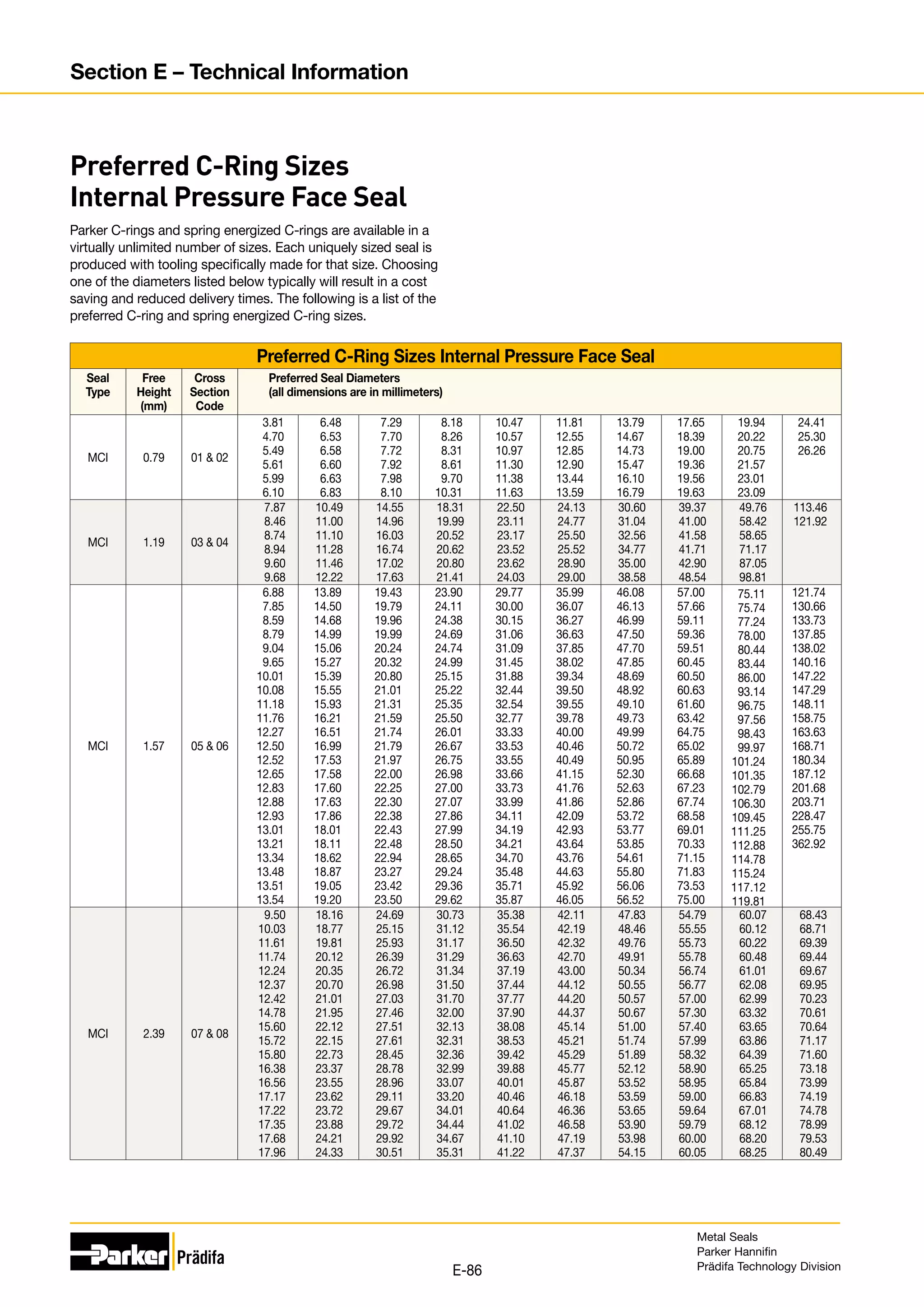
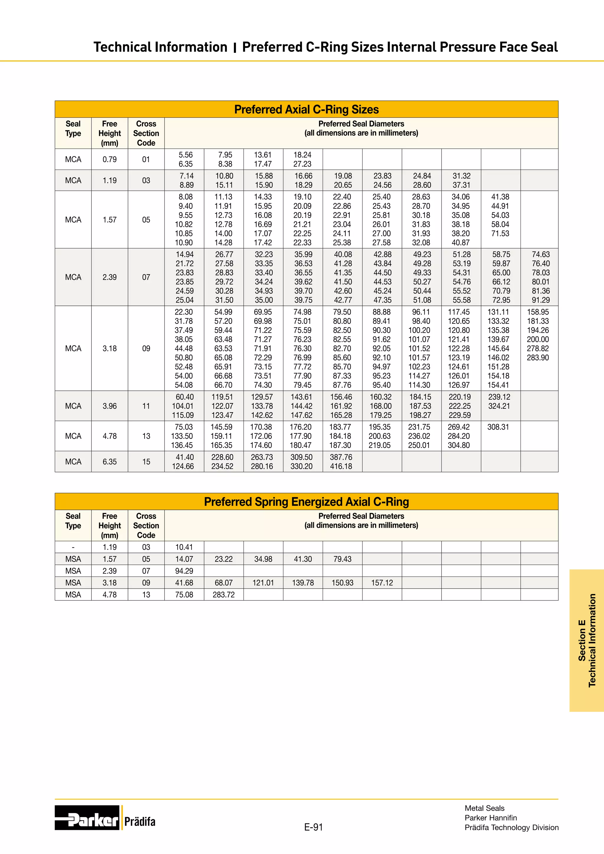
![Preferred C-Ring Sizes Internal Pressure Face Seal
Seal
Type
Free
Height
(mm)
Cross
Section
Code
Preferred Seal Diameters
(all dimensions are in millimeters)
MCI
[cont.]
2.39 07 08
80.67
80.98
82.70
85.85
85.88
87.00
87.38
88.19
88.65
89.05
90.65
91.01
91.11
93.83
94.01
94.21
97.00
100.25
101.35
101.42
102.44
102.54
105.92
107.77
108.41
109.91
111.15
113.00
113.08
114.73
114.81
115.49
117.47
119.20
119.30
119.33
119.99
120.47
121.01
121.13
121.74
122.81
123.60
123.70
123.80
124.99
126.67
129.31
130.30
130.33
131.17
133.17
134.87
135.71
136.35
139.24
140.21
145.44
147.22
147.85
149.94
152.22
153.67
158.70
160.27
176.00
184.30
203.20
209.55
273.58
MCI 3.18 09 10
22.00
24.71
26.31
27.10
28.60
28.68
29.54
29.69
30.05
31.01
32.66
32.72
33.27
35.13
35.56
35.84
36.14
36.60
36.93
37.41
37.64
37.80
39.01
39.90
40.59
41.71
41.81
41.91
43.71
43.82
44.60
45.36
45.72
46.33
46.94
47.12
47.55
48.26
48.62
50.01
50.17
50.22
50.39
51.99
53.21
53.23
54.89
54.94
55.32
55.60
55.83
56.72
56.77
56.90
57.99
59.69
59.79
60.07
61.11
61.34
61.49
61.72
61.80
62.03
62.10
62.94
63.07
63.20
63.25
63.37
64.14
64.26
64.82
65.61
65.99
66.29
66.42
66.50
67.16
68.00
68.22
68.33
68.81
69.06
69.60
69.90
70.23
71.04
71.30
71.32
71.91
72.01
72.78
73.03
73.89
73.99
74.35
74.91
75.41
75.77
75.84
76.00
76.58
77.01
77.52
77.60
79.12
80.49
80.70
82.37
82.63
82.80
84.46
84.51
84.63
85.42
85.52
85.62
87.94
89.54
89.81
91.24
91.82
92.00
92.84
93.22
93.40
94.74
94.89
95.00
95.38
96.57
98.17
98.45
99.06
99.24
99.47
99.75
99.82
100.61
101.22
102.41
102.77
102.92
103.10
104.52
104.77
105.31
106.10
106.58
108.33
109.91
111.25
112.32
113.16
114.20
114.22
116.10
116.54
117.60
117.78
117.86
119.79
119.81
119.89
120.52
120.65
120.83
122.99
125.40
125.60
125.73
125.78
126.31
127.38
128.57
128.90
129.24
129.26
129.41
130.56
130.99
131.95
132.87
136.65
136.80
137.01
137.16
138.10
139.52
142.75
143.41
145.62
146.05
146.51
148.01
149.48
150.34
150.88
151.21
151.76
152.60
153.54
153.85
155.57
155.85
156.03
156.82
157.00
158.55
162.31
165.10
167.39
167.59
169.49
170.99
171.45
173.20
174.68
179.22
179.40
184.00
184.61
190.55
191.82
193.19
194.82
197.87
202.95
209.55
228.83
252.88
MCI 3.96 11 12
32.46
37.47
40.26
44.12
45.03
46.41
52.38
52.45
53.47
56.01
59.49
59.94
64.52
65.41
68.43
69.57
69.65
69.72
70.99
72.47
73.41
75.64
75.87
77.19
77.22
77.78
79.50
82.45
83.57
86.11
86.41
87.17
89.99
91.44
94.41
94.77
98.86
101.14
102.46
102.62
104.27
106.48
106.83
108.43
109.60
110.59
111.99
113.77
114.10
115.87
117.22
119.76
121.87
127.46
128.98
129.44
130.00
130.33
132.00
135.10
138.71
139.50
139.75
139.83
147.50
147.70
147.80
151.16
151.66
161.49
161.72
175.01
179.02
183.31
185.75
196.60
212.72
MCI 4.78 13 14
43.74
50.42
52.45
66.50
69.42
74.17
82.27
91.90
96.14
97.33
97.54
101.83
101.98
103.45
103.68
103.89
104.44
105.46
108.58
108.76
109.80
110.87
112.75
114.05
116.81
117.96
119.91
120.01
123.57
126.42
126.54
127.94
128.19
129.97
131.27
131.90
133.60
135.99
137.01
139.80
144.20
146.94
146.96
147.65
149.94
150.06
150.14
152.88
154.99
158.93
159.49
160.40
160.53
161.82
167.08
167.23
169.67
173.33
174.37
177.55
180.72
182.40
182.58
183.26
190.14
202.74
225.22
234.98
263.52
MCI 6.35 15 16
99.44
119.38
119.71
123.62
124.36
129.69
132.69
137.21
138.56
144.07
145.67
153.09
167.13
213.61
MCI 9.53 17 18 151.61
Continued on next page.
Metal Seals
Parker Hannifin
Prädifa Technology Division
E-87
Section
E
Technical
Information
Technical Information I Preferred C-Ring Sizes Internal Pressure Face Seal](https://image.slidesharecdn.com/metalsealdesignguidemetricparker-220122070824/75/Metal-seal-design-guide-metric-Parker-87-2048.jpg)
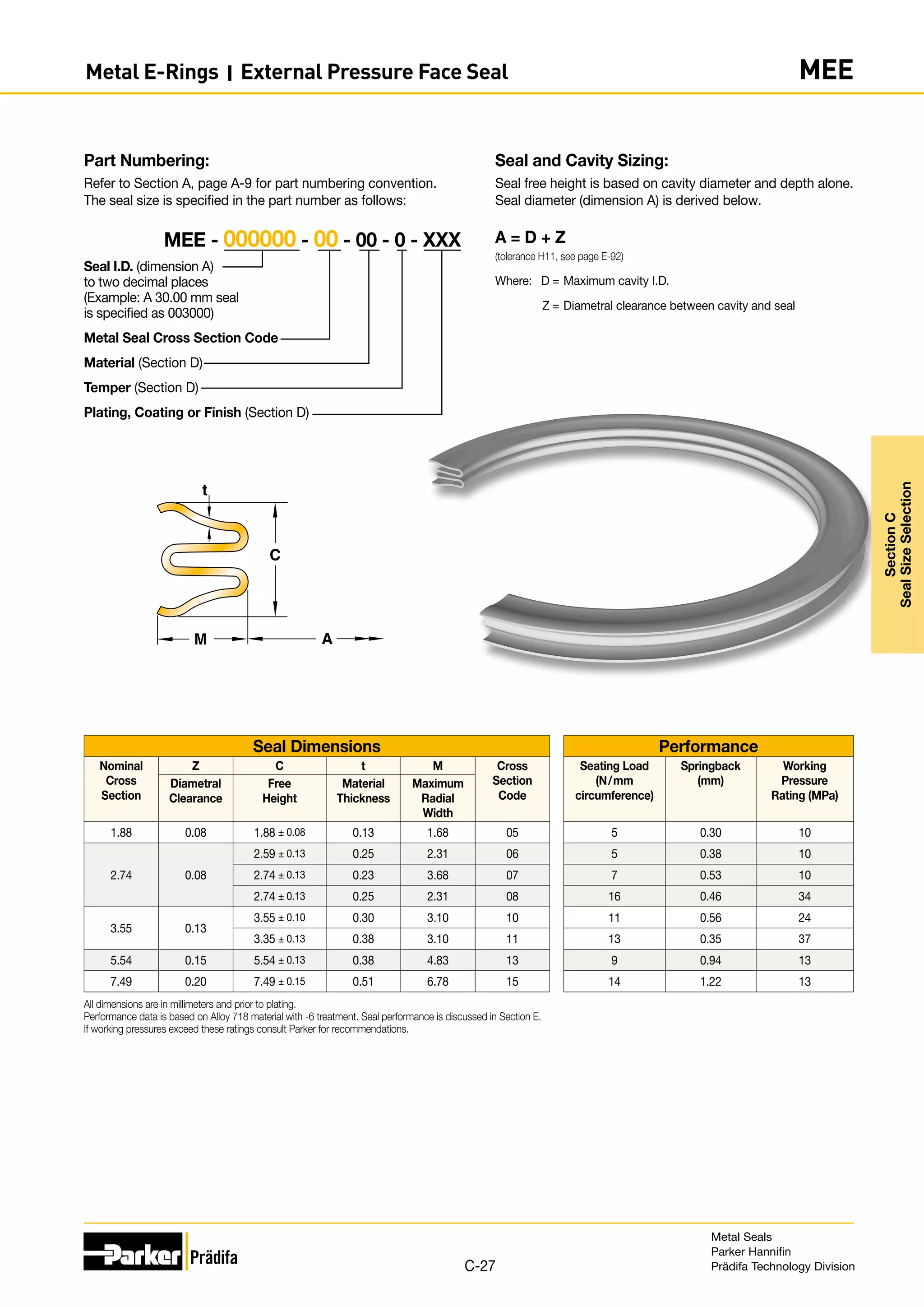
![Pressure
to obtain
multiply
atmosphere bar inches of
mercury
inches of
water
millimeters
of mercury
(Torr)
millimeters
of
water
kPa MPa Newtons/
m2
(Pascal)
pounds/
square
inch
atmosphere by 1 1.0133 29.9210 4.0678×10²
7.6000×10²
1.0332×10⁴
1.0133×10⁻¹
1.0133×10⁻¹
1.0133×10⁵
14.6960
bar by 9.8692×10-1
1 29.5300 4.0146×10²
7.5006×10²
1.0197×10⁴
1.000×10⁻²
1.0000×10⁻¹
1.0000×10⁵
14.5038
inches of
mercury
by 3.3421×10⁻²
3.3864×10⁻²
1 13.5950 25.4000 3.4532×10²
3.3864 3.3864×10⁻³
3.3864×10³
4.9116×10⁻¹
inches of
water
by 2.4584×10⁻³
2.4840×10⁻³
7.3556×10⁻²
1 1.8685 25.4000 2.4910×10⁻¹
2.4910×10⁻²
2.4910×10²
3.6128×10⁻²
mmof
mercury(Torr)
by 1.3158×10⁻³
1.3332×10⁻³
3.9370×10⁻²
5.3520×10⁻¹
1 13.5950 1.3332×10⁻¹
9.8068 1.3332×10²
1.9337×10⁻²
millimeters
of water
by 9.6787×10⁻⁵
9.8068×10⁻⁵
2.8959×10⁻³
3.9370×10⁻²
7.3556×10⁻²
1 9.8068×10⁻³
1.0000×10⁻³
9.8068 1.4223×10-3
kPa by 9.8692×10-3
1.0000×10⁻²
2.9530×10⁻¹
4.0146 7.5006 1.0197×10⁻²
1 1.0000×10⁻⁶
1.0000×10³
1.4504×10-1
MPa by 9.8692 10.0000 2.9530×10²
4.0146×10³
7.5006×10³
1.0197×10⁵
1.0000×10⁻⁶
1 1.0000×10⁶
1.4504×10²
Newtons/
m2
(Pascal)
by 9.8692×10⁻⁶
1.0000×10⁻⁵
2.9530×10⁻⁴
4.0146×10⁻³
7.5006×10⁻³
1.0197×10⁻¹
6.8948×10⁻³
6.8948×10⁻³
1 1.4504×10⁻⁴
pounds/
square inch
by 6.8046×10⁻²
6.8947×10⁻²
2.0360 27.6810 51.7144 7.0310×10²
6.8948 6.8948×10⁻³
6.8948×10³
1
Torque [Moment]
to obtain
multiply
N-m kg-m kg-cm ft-lb Inch-lb
N-m by 1 0.1020 10.1970 0.7376 8.8509
kg-m by 9.8068 1 100.0000 7.2330 86.7942
kg-cm by 0.0981 0.0100 1 0.0723 0.8679
ft-lb by 1.3558 0.1383 13.8255 1 12.0000
inch-lb by 0.1130 0.0115 1.1522 0.0833 1
Force
to obtain
multiply
newton kilogram pound
newton by 1 0.1020 0.2248
kilogram by 9.8068 1 2.2046
pound by 4.4482 0.4536 1
Distributed Force [Force per unit length]
to obtain
multiply
N/mm kg/cm lb/in
N/mm by 1 1.0197 5.7102
kg/cm by 0.9807 1 5.5997
lb/in by 0.1751 0.1786 1
For leakage rate conversion refer to page E-80.
1200
1000
800
600
400
200
0
-200
-400
KELVIN (K)
CELSIUS (°C )
FAHRENHEIT
(°F
)
RANKINE
(R)
1860
1460
873
673
473
273
73 1073
600
400
200
0
-200 800
1260
1060
860
660
460
260
60
°F = °C ( ) + 32
°C = (°F - 32)
°R = °F + 460
K = °C + 273
K = °R ( )
9
5
5
9
5
9
Temperature
Conversion Tables
Metal Seals
Parker Hannifin
Prädifa Technology Division
E-93
Section
E
Technical
Information
Technical Information I Conversion Tables](https://image.slidesharecdn.com/metalsealdesignguidemetricparker-220122070824/75/Metal-seal-design-guide-metric-Parker-93-2048.jpg)