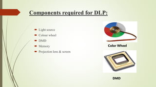
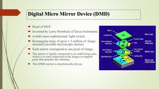
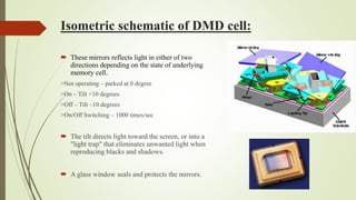
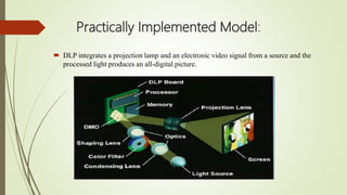
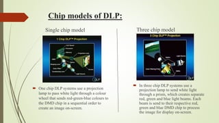
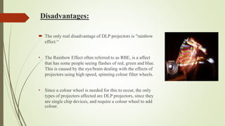
DIGITAL LIGHT PROCESSING AND IT’S
FUTURE APPLICATION
OUTLINE:
 Introduction
 History of Evolution
 Basic components of DLP
 How DLP works?
 Pixel structure of Digital Micro-mirror Device (DMD)cell
 Advantages & Disadvantages
 Applications
 Conclusion
 Future roadmap
 References
Introduction:
 Digital Light Processing (DLP) is a display technology developed by Texas
Instruments.
 It is based on an optical semiconductor, called a DMD, which uses mirrors made
of aluminium to reflect light to make the picture.
 DMD can be combined with image processing, memory , a light source and
optics to form a DLP system capable of projecting images with better colour
fidelity and consistency than current technology.
 It provides all-digital projection displays that offer superior picture quality in
terms of resolution, brightness, contrast.
History of innovation:
 DMD was invented in 1987 by Dr. Larry Hornbeck of Texas Instruments.
 In 1993, it named the new technology DLP and formed a separate group
to develop commercial display applications .
 In 1994, TI demonstrated DLP projectors for the first time.
 Since 2000, several DLP technology based products such as projectors,
HDTV’s, 3-D printer, etc were introduced .
Why DLP?
 The traditional CRT projectors have RGB tubes which
makes the entire cabinet bulky.
 The LCD projectors use LCD light gates for projecting,
which introduces pixelation effect.
 In order to overcome all the drawbacks of previous
techniques, DLP was developed.
Components required for DLP:
 Light source
 Colour wheel
 DMD
 Memory
 Projection lens & screen
DMD
Color Wheel
Digital Micro Mirror Device (DMD)
 Heart of DLP.
 Invented by Larry Hornbeck of Texas Instrument.
 world's most sophisticated light switch.
 Rectangular array of up to 1.3 million of hinge-
mounted movable microscopic mirrors.
 Each mirror correspond to one pixel of image.
 The mirror is rigidly connected to an underlying yoke,
which is in turn connected to the hinges to support
posts that attaches the substrate.
 This DMD mirror is electronically driven.
Isometric schematic of DMD cell:
 These mirrors reflects light in either of two
directions depending on the state of underlying
memory cell.
>Not operating – parked at 0 degree
>On – Tilt +10 degrees
>Off – Tilt –10 degrees
>On/Off Switching – 1000 times/sec
 The tilt directs light toward the screen, or into a
"light trap" that eliminates unwanted light when
reproducing blacks and shadows.
 A glass window seals and protects the mirrors.
DLP: Adding Colors
 The white light passes through a color wheel
 The color wheel filters the light into red, green, and blue.
 A single-chip DLP projection system can create at least 16.7 million
colors.
 3-DMD chip system is capable of producing no fewer than 35 trillion
colors.
How DLP works ?
 Signal Conversion
 Gray Scale Image
 Color Creation
Step 1 – Signal Conversion:
 Accepts both analog or digital signal.
 All signals must be converted into digital.
 The digital signal, enables mirrors to tilt
towards “On” or away from “Off” light source.
Step 2 – Gray Scale Image:
 On” – light Pixel vs. “Off” – Dark Pixel
 Mirror switched on more frequently than off – Reflects Light Gray Pixel
 Rapid Switching allows up to 1024 shades of gray reflections
 Digitalized video signal entering DMD get converted into highly
detailed grayscale image
Not present
Step 3 – Color Creation:
 Color is added as white light from the lamp passes through a color wheel
filter.
 Color Wheel – RED, GREEN & BLUE.
 Mirrors on DMD are tilted on for the exact amount of time required for
each basic color.
 Only 1 color is shined onto DMD at a time.
 When spinning fast enough, human eyes blend alternating flashes to view
“more” colors in the projected image.
Color wheel present
Practically Implemented Model:
 DLP integrates a projection lamp and an electronic video signal from a source and the
processed light produces an all-digital picture.
Chip models of DLP:
Single chip model
 One chip DLP systems use a projection
lamp to pass white light through a colour
wheel that sends red-green-blue colours to
the DMD chip in a sequential order to
create an image on-screen.
Three chip model
 In three chip DLP systems use a
projection lamp to send white light
through a prism, which creates separate
red, green and blue light beams. Each
beam is send to their respective red,
green and blue DMD chip to process
the image for display on-screen.
Advantages:
 Brighter
-Because it brings more light from lamp to screen.
 Sharper
-As it can produce the closest mirror image of an incoming video of any
resolution .
 Versatile
-DLP projectors are small and light weight.
 Reliable
-it is capable of recreating the source material
Disadvantages:
 The only real disadvantage of DLP projectors is "rainbow
effect.“
• The Rainbow Effect often referred to as RBE, is a affect
that has some people seeing flashes of red, green and blue.
This is caused by the eye/brain dealing with the effects of
projectors using high speed, spinning colour filter wheels.
• Since a colour wheel is needed for this to occur, the only
types of projectors affected are DLP projectors, since they
are single chip devices, and require a colour wheel to add
colour.
LCD V/s DLP Projector:
DLP V/s LCD
Applications:
 DLP Televisions
 Digital Light Processing Television is a
technology that uses one, or sometimes three,
electronic chips called Digital Micro-mirror
Devices, or DMDs, to produce a vivid picture
with a high contrast ratio on a high-definition
large-screen TV.
 DLP is definitely fast enough to steer the light
around the falling rain drop – thereby avoiding
the blurred vision and blooming effect.
Conclusion:
 As compact disc revolutionized the audio industry, DLP will
revolutionize the video projection.
 Based on the reflected light produced by multiple mirrors, DLP
creates a final link to display visual information.
Future Roadmap:
 DLP projectors are becoming more common in business environments as
it incorporates high-definition image creation.
 Scientist and developers are likely to discover even more uses for DMDs
and DLP technology in the future.
References:
 Digital Light Processing™: A New MEMS-Based Display Technology Larry J. Hornbeck
Texas Instruments
 http://www.ti.com
 http://www.christiedigital.com
 Rainbow effect,http://www.projectorreviews.com

Digital light processing and its future application.

  • 1.
    DIGITAL LIGHT PROCESSINGAND IT’S FUTURE APPLICATION
  • 2.
    OUTLINE:  Introduction  Historyof Evolution  Basic components of DLP  How DLP works?  Pixel structure of Digital Micro-mirror Device (DMD)cell  Advantages & Disadvantages  Applications  Conclusion  Future roadmap  References
  • 3.
    Introduction:  Digital LightProcessing (DLP) is a display technology developed by Texas Instruments.  It is based on an optical semiconductor, called a DMD, which uses mirrors made of aluminium to reflect light to make the picture.  DMD can be combined with image processing, memory , a light source and optics to form a DLP system capable of projecting images with better colour fidelity and consistency than current technology.  It provides all-digital projection displays that offer superior picture quality in terms of resolution, brightness, contrast.
  • 4.
    History of innovation: DMD was invented in 1987 by Dr. Larry Hornbeck of Texas Instruments.  In 1993, it named the new technology DLP and formed a separate group to develop commercial display applications .  In 1994, TI demonstrated DLP projectors for the first time.  Since 2000, several DLP technology based products such as projectors, HDTV’s, 3-D printer, etc were introduced .
  • 5.
    Why DLP?  Thetraditional CRT projectors have RGB tubes which makes the entire cabinet bulky.  The LCD projectors use LCD light gates for projecting, which introduces pixelation effect.  In order to overcome all the drawbacks of previous techniques, DLP was developed.
  • 6.
    Components required forDLP:  Light source  Colour wheel  DMD  Memory  Projection lens & screen DMD Color Wheel
  • 7.
    Digital Micro MirrorDevice (DMD)  Heart of DLP.  Invented by Larry Hornbeck of Texas Instrument.  world's most sophisticated light switch.  Rectangular array of up to 1.3 million of hinge- mounted movable microscopic mirrors.  Each mirror correspond to one pixel of image.  The mirror is rigidly connected to an underlying yoke, which is in turn connected to the hinges to support posts that attaches the substrate.  This DMD mirror is electronically driven.
  • 8.
    Isometric schematic ofDMD cell:  These mirrors reflects light in either of two directions depending on the state of underlying memory cell. >Not operating – parked at 0 degree >On – Tilt +10 degrees >Off – Tilt –10 degrees >On/Off Switching – 1000 times/sec  The tilt directs light toward the screen, or into a "light trap" that eliminates unwanted light when reproducing blacks and shadows.  A glass window seals and protects the mirrors.
  • 9.
    DLP: Adding Colors The white light passes through a color wheel  The color wheel filters the light into red, green, and blue.  A single-chip DLP projection system can create at least 16.7 million colors.  3-DMD chip system is capable of producing no fewer than 35 trillion colors.
  • 10.
    How DLP works?  Signal Conversion  Gray Scale Image  Color Creation
  • 11.
    Step 1 –Signal Conversion:  Accepts both analog or digital signal.  All signals must be converted into digital.  The digital signal, enables mirrors to tilt towards “On” or away from “Off” light source.
  • 12.
    Step 2 –Gray Scale Image:  On” – light Pixel vs. “Off” – Dark Pixel  Mirror switched on more frequently than off – Reflects Light Gray Pixel  Rapid Switching allows up to 1024 shades of gray reflections  Digitalized video signal entering DMD get converted into highly detailed grayscale image Not present
  • 13.
    Step 3 –Color Creation:  Color is added as white light from the lamp passes through a color wheel filter.  Color Wheel – RED, GREEN & BLUE.  Mirrors on DMD are tilted on for the exact amount of time required for each basic color.  Only 1 color is shined onto DMD at a time.  When spinning fast enough, human eyes blend alternating flashes to view “more” colors in the projected image. Color wheel present
  • 15.
    Practically Implemented Model: DLP integrates a projection lamp and an electronic video signal from a source and the processed light produces an all-digital picture.
  • 16.
    Chip models ofDLP: Single chip model  One chip DLP systems use a projection lamp to pass white light through a colour wheel that sends red-green-blue colours to the DMD chip in a sequential order to create an image on-screen. Three chip model  In three chip DLP systems use a projection lamp to send white light through a prism, which creates separate red, green and blue light beams. Each beam is send to their respective red, green and blue DMD chip to process the image for display on-screen.
  • 17.
    Advantages:  Brighter -Because itbrings more light from lamp to screen.  Sharper -As it can produce the closest mirror image of an incoming video of any resolution .  Versatile -DLP projectors are small and light weight.  Reliable -it is capable of recreating the source material
  • 18.
    Disadvantages:  The onlyreal disadvantage of DLP projectors is "rainbow effect.“ • The Rainbow Effect often referred to as RBE, is a affect that has some people seeing flashes of red, green and blue. This is caused by the eye/brain dealing with the effects of projectors using high speed, spinning colour filter wheels. • Since a colour wheel is needed for this to occur, the only types of projectors affected are DLP projectors, since they are single chip devices, and require a colour wheel to add colour.
  • 19.
    LCD V/s DLPProjector: DLP V/s LCD
  • 20.
    Applications:  DLP Televisions Digital Light Processing Television is a technology that uses one, or sometimes three, electronic chips called Digital Micro-mirror Devices, or DMDs, to produce a vivid picture with a high contrast ratio on a high-definition large-screen TV.  DLP is definitely fast enough to steer the light around the falling rain drop – thereby avoiding the blurred vision and blooming effect.
  • 21.
    Conclusion:  As compactdisc revolutionized the audio industry, DLP will revolutionize the video projection.  Based on the reflected light produced by multiple mirrors, DLP creates a final link to display visual information.
  • 22.
    Future Roadmap:  DLPprojectors are becoming more common in business environments as it incorporates high-definition image creation.  Scientist and developers are likely to discover even more uses for DMDs and DLP technology in the future.
  • 23.
    References:  Digital LightProcessing™: A New MEMS-Based Display Technology Larry J. Hornbeck Texas Instruments  http://www.ti.com  http://www.christiedigital.com  Rainbow effect,http://www.projectorreviews.com