Download to read offline


![27
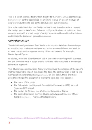
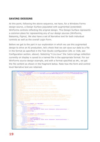
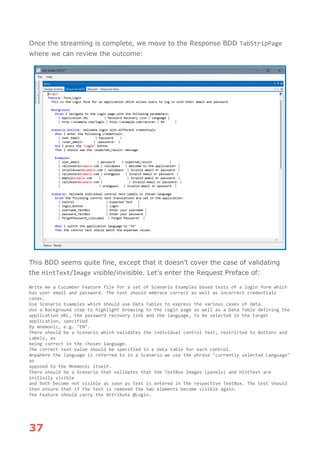
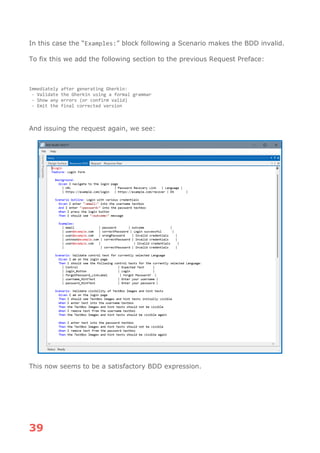
So, for example we see in the Figma project structure a “text box” containing a
“rectangle”, a “button” containing a “rectangle” and so on. These subtleties
need to be dealt with as part of our process of transforming the Figma world on
to our generic Design Surface.
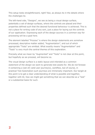
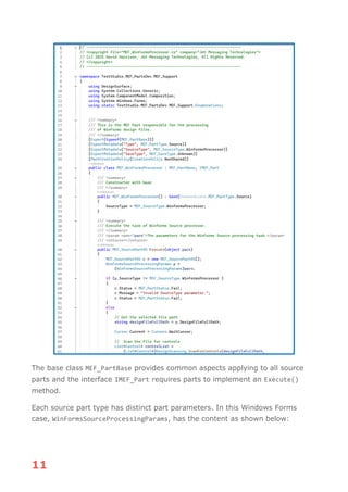
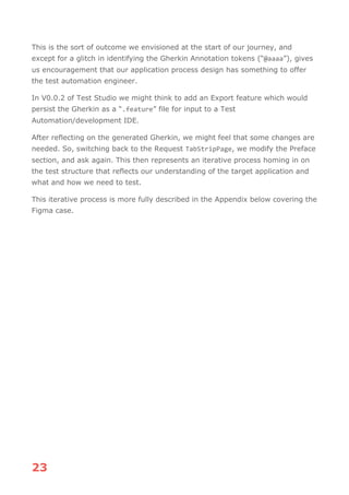
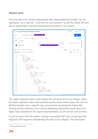
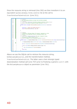
FIGMA DESIGN STRUCTURE
Let us go through the sections of the structure and see their equivalence on the
design. The naming convention of the highlighted node text is:
figma-design-name [winforms-type-short-name:winforms-identifier-name]
This text adaptation is vital to our overall process.](https://image.slidesharecdn.com/designfortest-251213093713-8d5032cb/85/Design-For-Test-Getting-Test-Automation-value-from-Design-Expressions-29-320.jpg)
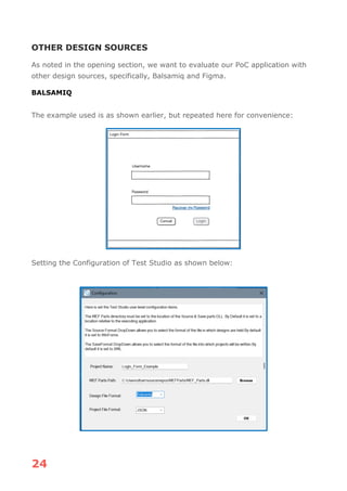
![28
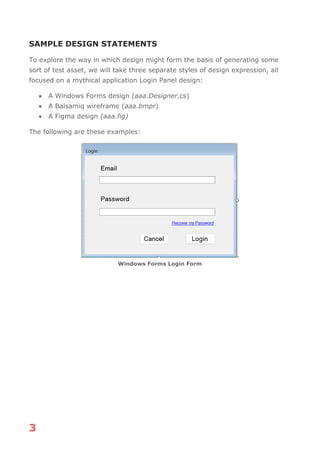
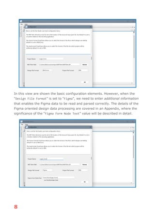
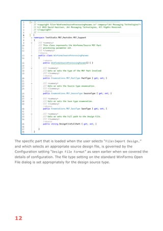
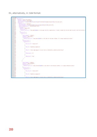
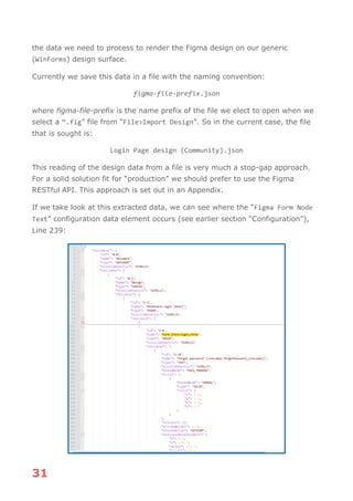
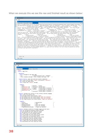
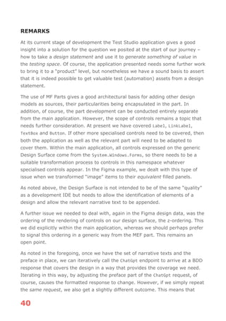
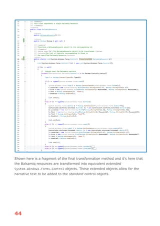
1. Form [Form:login_Form]
This represents the surrounding container of all the elements of the
design, the form:
2. Group [Image:SKIP]
This part of the design we don’t see as relevant to the test automation
solution, thus it is marked with the special winforms-identifier-name of
“SKIP”. No processing, transformation will happen when we encounter this
section in the Figma design data.
3. Login btn [Button:login_Button]
This represents the action button which actions the login process. In the
design it also plays the role of a container, enclosing the elements (login
[Label:login_Text]) and (Rectangle [Rectangle:login_ButtonRectangle]).](https://image.slidesharecdn.com/designfortest-251213093713-8d5032cb/85/Design-For-Test-Getting-Test-Automation-value-from-Design-Expressions-30-320.jpg)
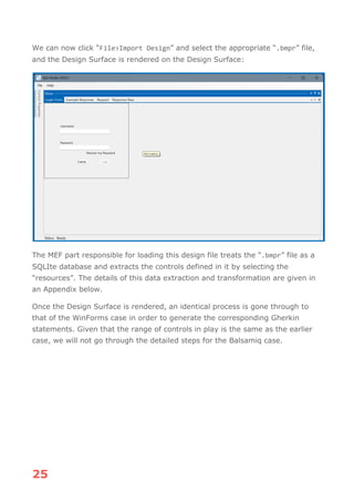
![29
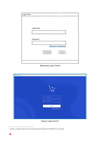
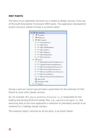
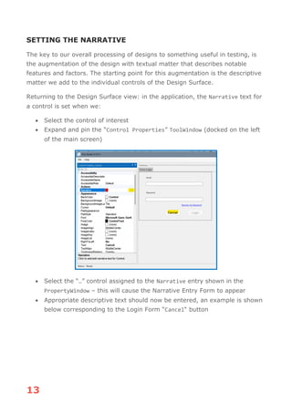
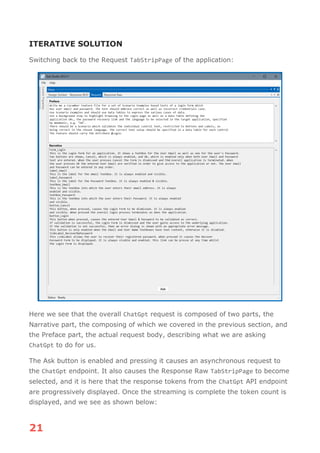
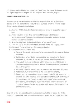
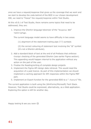
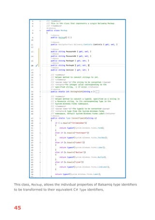
The “Label” represents the label of the login button, whilst the “Rectangle”
represents its bounding box.
4. Password [TextBox:textbox_Password]
This component is the text box into which password is to be entered. Just
as in the case of the login button, this component acts as container for
other parts, in this case; (lock [Image:password_LockImage]), (password
[Label:password_HintText]) and (Rectangle
[Rectangle:password_TextBox]). The image element operates as a fixed
graphic, whilst the “password” text appears to operate as a hint text; it is
shown when the enclosing text box has no containing text but has its
visibility set to false when the user enters any characters. S in the case of
the button, the “Rectangle” plays the role of a bounding box for the
TextBox itself.
5. Username [TextBox:username_TextBox]
This is the TextBox into which the user enters there username. Its
structure is the same as that of the “textbox_Password”, it has a small
graphic item, an enclosing “Rectangle” and hint text.
6. Forgot password? [LinkLabel:forgotPassword_LinkLabel]
This element acts as a password recovery link.](https://image.slidesharecdn.com/designfortest-251213093713-8d5032cb/85/Design-For-Test-Getting-Test-Automation-value-from-Design-Expressions-31-320.jpg)

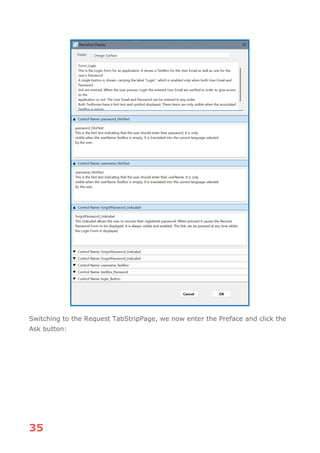
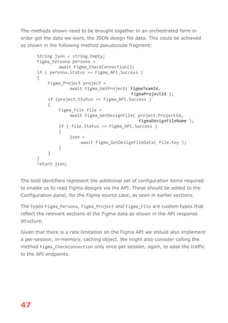

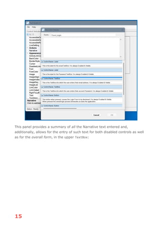
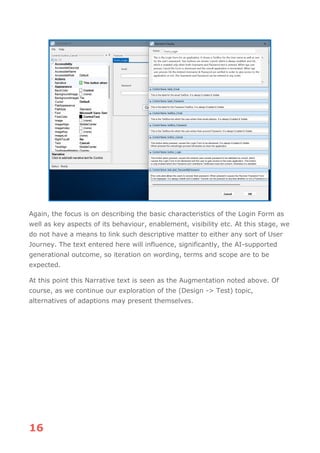
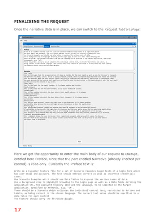
This article explores the process of taking Design Expressions, such as Winforms, Balsamiq or Figma and generating something of value to the Test Automation space. It does this using a working proof-of-concept (PoC) application. This application shows clearly what's involved and how BDD/Gherkin can be generated from Design Expressions using an AI-assisted process. Detailed insight into this PoC application is given as well as a summary of where further work is needed. It is possible to see this application as the basis of a commercial product.


![[webinar] Cutting-edge Functional UI Testing Techniques - w/ Adam Carmi](https://cdn.slidesharecdn.com/ss_thumbnails/20200325-functionalvisualai-200330145548-thumbnail.jpg?width=640&height=640&fit=bounds)