Downloaded 19 times
![IJRET: International Journal of Research in Engineering and Technology eISSN: 2319-1163 | pISSN: 2321-7308
_______________________________________________________________________________________
Volume: 04 Issue: 09 | September-2015, Available @ http://www.ijret.org 411
TABLE 1: SETUP TIME STUDY DETAIL AFTER
IMPLEMENTATION
Sl
no
Component
Name
Avg Set
up time
in mins
before
Avg
Set up
time
in
mins
After
Efficiency
increase
1 Cover clutch 47 11 77%
2 Pipe intake 34 10 71%
3 Crank Shaft 31 3.5 89%
ACKNOWLEDGMENT
[1]. I proudly vest my honor to Management of East Point
College of Engineering and Technology, Bengaluru
for providing me an opportunity to work on this
project as part of my research work.
[2]. It gives me immense pleasure to express my deep
sense of gratitude to our beloved Dr. B M Satish,
Principal, EPCET, whose words of advice have always
been a constant source of inspiration for me, and I
would like to take this opportunity to thank Dr. R
Venkatram, Director, EPCET, Bengaluru.
[3]. I would like to express my heartfelt thanks to Dr. A K
Murthy, Head of the Department of Mechanical
Engineering, for his valuable advice and
encouragement to me in completing this project work.
[4]. I take it as a high esteemed privilege in expressing my
sincere gratitude, heartfelt respect and regards to my
guide Prof. M S Aswathnarayan, Associate Professor,
Department of ME, EPCET, Bengaluru. For the co-
operation and support which helped me to accomplish
my Project work. Also I am thankful to him for his
valuable guidance and innovative ideas given to me
during the course of my Project work.
[5]. I would like to thank my parents and friends all of
those who supported me in any respect during the
project.
REFERENCES
[1]. Frieder, R., Kumaresan, S., and Sances, A., "Modular
medical evacuation fixture for use in military and
disaster response vehicles," SAE technical paper
2007-01-1767, 2007, DOI:10.4271/2007-01-1767.
[2]. LI, Y. and Bahr, B., "The design of a flexible fixture
for aircraft assembly," SAE technical paper 961885,
2006, DOI:10.4271/961885
[3]. Moohl, J., "APPLYING jigs and fixtures to engine-
block machining," SAE technical paper 250056,
2009, DOI:10.4271/250056.
[4]. BI, Z. M., Zhang, W. J.: Flexible fixture design and
automation: review, issues and future directions,
international journal of production research, 2010,
Vol.39, NO. 13, PP. 2867-2894.](https://image.slidesharecdn.com/designandfabricationofmodularfixtureforcmminspection-160916052141/75/Design-and-fabrication-of-modular-fixture-for-cmm-inspection-6-2048.jpg)

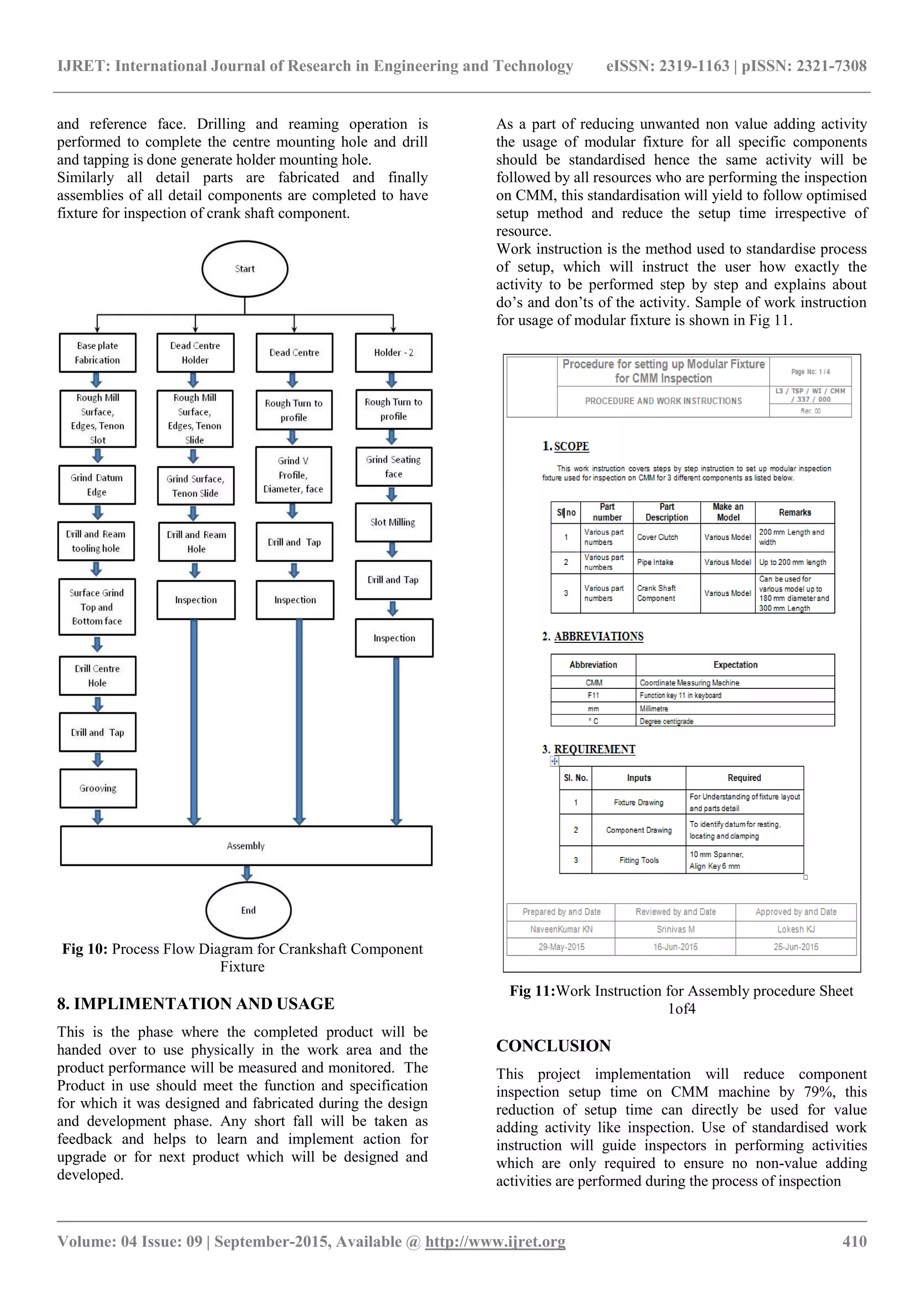
This document discusses the design and fabrication of a modular fixture for coordinate measuring machine (CMM) inspections aimed at reducing setup time and improving utilization of the machine. The modular fixture allows for components of various configurations to be efficiently held and inspected, with a standardization process that minimizes non-value adding activities. The implementation resulted in a significant reduction in setup times by up to 79%, allowing more time for actual inspection activities.


![Apqp+english+version[1]](https://cdn.slidesharecdn.com/ss_thumbnails/apqpenglishversion1-121219073626-phpapp02-thumbnail.jpg?width=640&height=640&fit=bounds)


