SlideShare a Scribd company logo
1 of 204
Download to read offline
UNIT- I
Fig1.1
1. PROCESS PLANNING
According to ASTM, ―process planning is defined as the systematic determination
of the methods by which a product is to be manufactured economically and
competitively‖.
Process planning comprises the selection and sequencing of processes and
operations to transform a chosen raw material into a finished component. It is the act
of preparing detailed work instructions to produce a component. This includes the
selection of manufacturing processes and operations, production equipment, tooling
and jigs and fixtures. It will also normally include determining manufacturing
parameters and specifying criteria for the selection of quality assurance (QA)
Visit : www.Civildatas.com
Visit : www.Civildatas.com Visit : www.Civildatas.com
w
w
w
.
C
i
v
i
l
d
a
t
a
s
.
c
o
m
methods to ensure product quality.
1.1 Process planning the design/manufacture interface
Fig 1.2 Main functions involved in product design and manufacture
There are various functions within a manufacturing Organization. In terms of the
successful product design and manufacture, there are three major functions
involved, namely marketing and sales, design and manufacturing in fig 1.2. The
numerous tasks undertaken by these functions in the design and manufacture of a
product traditionally occur in a sequential manner. Generally, marketing is
responsible for assessing the current market trends and needs and generating new
product ideas. Also based on the market assessment, marketing is responsible for
generating specifications for the further development of existing products. The role
of sales is to generate interest in the products being manufactured and obtain firm
orders. The design function will take the product ideas and specifications generated
by marketing and provide a detailed specification of all the components and
Visit : www.Civildatas.com
Visit : www.Civildatas.com Visit : www.Civildatas.com
w
w
w
.
C
i
v
i
l
d
a
t
a
s
.
c
o
m
sub-assemblies for the finished product. This will include all detail drawings,
assembly drawings and bills of materials. Very often, a prototype of the product will
be developed to help validate the design and establish which manufacturing facilities
are required.
The product and process requirements generated at the design and development
stage are then passed to the manufacturing function. These will be used to prepare
the detailed work instructions required to manufacture the product. These will then
be passed to the manufacturing facility for execution. Therefore, although the design
and manufacturing functions are separated, the process planning activity links them
as shown in fig 1.3. Thus, process planning is the design/ manufacture interface in
this sequential approach. This sequential approach to the design and manufacture of
products has relied on there being a long product life cycle, that is, a stable demand
for the product over a long period of time. However, in today's highly competitive
global market, this is very often not the case. Therefore, manufacturing
organizations have had to consider ways of compressing the time taken to design
and manufacture products or the time to market as it is also known. Some have
focused on the implementation of organizational change to achieve shorter times to
market using matrix-based structures and encouraging all functions or departments
to contribute to the development, design and manufacture of their products. This
cooperative approach, based on the use of cross-functional teams, is known as
simultaneous or concurrent engineering.
Fig 1.3 Process planning - the design~manufacture interface
The functions of such cross-functional teams include
Visit : www.Civildatas.com
Visit : www.Civildatas.com Visit : www.Civildatas.com
w
w
w
.
C
i
v
i
l
d
a
t
a
s
.
c
o
m
 ensuring all team members understand enough about the product
functions to be able to contribute to the design decisions;
 determining the appropriate design and manufacturing methods to use;
 relating all product functions to manufacturing methods.
1.3 Process planning activities
1. Drawing interpretation
The first step in preparing the process plan for any component or product is to
consult the engineering drawings. The drawing of the component under
consideration will contain a variety of information which can help assess the
processing requirements. The interpretation of the drawing will include assessing
the part geometry, dimensions and associated tolerances, geometric tolerances,
surface finish specifications, the material specification and the number of parts
required. From this interpretation, the critical processing factors can be identified
and give some indication of candidate manufacturing processes. For example, all
processes and production equipment will have an economic batch quantity, that is,
the batch size with which the process or production equipment becomes
economically viable to use. Therefore, the number of parts required would eliminate
certain processes and production equipment from the list of possible candidate
processes while indicating the suitability of others.
2. Material evaluation and process selection
Although the design engineer specifies the material to be used, the process planner
will, on occasion, have to enter into a meaningful dialogue with the design engineer
about the materials specified, based on the availability of manufacturing processes.
Therefore, a thorough knowledge of the materials used in manufacturing is essential
for effective process planning. This is because every material has different
properties and, based on these, will be more suited to particular processes than
others. For example, brittle materials are more suited to casting or material removal
processes. On the other hand, they are not well suited for use with forming
processes. Also, some materials undergo changes in properties during processing
and therefore due consideration must be given to this fact. Finally, it is the job of the
manufacturing engineer to specify the raw material billet form for the component.
This will include the size and any special requirements for the raw materials, for
example, heat treatment. Knowledge of material properties is essential to carry out
this task, again because some materials undergo changes in their properties during
Visit : www.Civildatas.com
Visit : www.Civildatas.com Visit : www.Civildatas.com
w
w
w
.
C
i
v
i
l
d
a
t
a
s
.
c
o
m
processing. For example, during forging a material may undergo dynamic loading
and it is important to know how it will react to this sudden loading. Therefore, it is
important to know about the material's impact resistance or toughness, as it is also
known. Based on the drawing interpretation and the materials evaluation, a shortlist
of candidate processes can be drawn up. Using some general rules for process
selection and criteria such as material form, component size and weight, economic
considerations, dimensional and geometric accuracy, surface finish specification,
batch size and production rate, the shortlist can be evaluated further and a final
selection of processes and operations identified.
3. Selection of machines and tooling
Once the process planner has determined which processes are being used, the
specific production equipment required for this must be selected. Typical factors to
be considered include the component size and weight, the physical size and
construction of the machine, and the power and torque of the machine. Another
factor to be considered is the number and type of tools available for the machine
under consideration. Once the equipment decision has been made, the specific
tooling for each operation must be identified. Successful processing of a component
relies heavily on the selection of appropriate tools, particularly for machining. This
should be eased by the fact that available tooling should be a factor in the selection
of the machine in the first instance. There are various factors
that will be considered in selecting an appropriate tool including work piece
material, type of cut, tool material, machining data and quality/capability
requirements. For example, all processes and production equipment have an
inherent capability in terms of surface finish. Thus, any process or production
equipment that can't meet the surface finish specification would be discounted at an
early stage of the selection process.
4. Setting process parameters
Once the machines and tooling have been selected, specific parameters must be
established for each operation for each machine. These include calculating
appropriate feeds, speeds and depth of cut for each tool for each operation. It is also
normal to calculate the time taken for each operation based on the part geometry and
the speeds and feeds employed. Times taken for non-value added tasks, such as
setting and handling, are also established. This enables the total time taken for the
job to be compiled. A major part of this task will be the use of reference materials
such as machine manufacturer's data and tool manufacturer's data.
Visit : www.Civildatas.com
Visit : www.Civildatas.com Visit : www.Civildatas.com
w
w
w
.
C
i
v
i
l
d
a
t
a
s
.
c
o
m
5. Work holding devices
In the context of this book, work holding devices are classified into two categories.
These are general-purpose work holders, which include the likes of chucks and
collets, and specialist work holders, which are taken to mean jigs and fixtures. From
the drawing interpretation, the process planner identifies any general location and
restraint requirements and any critical location and restraint requirements. The
general requirements will be based on any dimensional and geometric tolerances
specified in the drawing, while the critical requirements will be based on any
instances of coupled dimensional and geometric tolerances. Having identified the
need for a jig or fixture for a particular operation and identified the location and
clamping requirements, this data will generally be passed to a specialist tool
designer. Based on these requirements, the tool designer will produce the detail
drawings and a general arrangement drawing of the workholding device to be
manufactured.
6. Selecting quality assurance methods
The critical processing factors such as dimensional and geometric tolerances and
surface finish specifications will have been identified during the drawing
interpretation. It is the job of the process planner to specify the inspection criteria for
all these critical processing factors as all manufacturing processes have some degree
of inherent variability. In some cases, the process planner might be responsible for
specifying the tools and techniques to be employed to ensure adherence to
specification. However, more commonly the inspection criteria will be passed to a
Quality Engineer who decides which tools and techniques are most appropriate.
Finally, it is important to strike the balance between ensuring the product quality and
avoiding unnecessary checking. The overuse of QA methods and inspection will add
to the processing time which, in turn, will add to the manufacturing costs.
7. Costing
The process planner is also tasked with estimating the costs of the process plan. This
means estimating the manufacturing costs of producing a component or product
based on the available cost and time data. This will be used to determine the unit cost
and the profitability of the product. Cost data will also be used to formulate the
process plan itself. Through establishing relationships between cost and volume,
decisions can be made about what material to use, the manufacturing processes to be
used, the batch size to be employed and whether to make or buy a product or
component. Furthermore, relative cost data for materials and processes is used to
help make process planning decisions.
Visit : www.Civildatas.com
Visit : www.Civildatas.com Visit : www.Civildatas.com
w
w
w
.
C
i
v
i
l
d
a
t
a
s
.
c
o
m
Preparing the process planning documentation
There are two documents involved in the preparation of the process plans.
These are:
1. routing sheets;
2. Operations list.
1. Routing sheets
The routing sheet, as its name suggests, specifies the route the raw material follows
through the manufacturing environment. It usually lists the production equipment
and tooling to be used. It is normal practice for the routing sheet to follow the
material through the manufacturing shop floor providing 'travel' information for the
operators. As stated it isquite often in the shop only a routing sheet will be used with
the fine details of production left to the highly skilled operators employed in such an
environment.
Fig1.4 Route sheet
2. Operations list
Once the routing of a component has been established, the detailed plan for every
operation can be prepared using an operations list. This specifies in more detail each
individual operation. It is usual for an operations list to be prepared for each
workstation listed on the routing sheet, although it may sometimes cover a group of
machines in a work cell. Although the content of an operations sheet will vary from
organization to organization, it will typically include details of tooling (including
Visit : www.Civildatas.com
Visit : www.Civildatas.com Visit : www.Civildatas.com
w
w
w
.
C
i
v
i
l
d
a
t
a
s
.
c
o
m
work holding devices), feeds and speeds, set-up and operation times.
Fig1.5 operations sheet
Miscellaneous documents
In some companies, the total process planning package may include further
documentation. For example, the calculations for the speeds and feeds detailed in the
operations list may be detailed in a speeds and feeds calculation sheet as illustrated
in Fig. 1.6. It can also be the case that further details of the tooling specified in the
operations list is detailed in a tooling list, an example of which is illustrated in Fig.
1.7. Finally, it is important to note that in some companies
a single process planning document may be used which is a combination of the
routing sheet and the operations list. From the brief descriptions given above, it can
be seen that the process plan provides the complete work instructions required for
the manufacture of a component or product. Consequently, these instructions will
affect the cost, quality and production rate of the component or product.
Visit : www.Civildatas.com
Visit : www.Civildatas.com Visit : www.Civildatas.com
w
w
w
.
C
i
v
i
l
d
a
t
a
s
.
c
o
m
Fig. 1.6 speeds/feeds calculation sheet
Visit : www.Civildatas.com
Visit : www.Civildatas.com Visit : www.Civildatas.com
w
w
w
.
C
i
v
i
l
d
a
t
a
s
.
c
o
m
Fig. 1.6 Tooling list
Table1.1 Process chart symbols
Visit : www.Civildatas.com
Visit : www.Civildatas.com Visit : www.Civildatas.com
w
w
w
.
C
i
v
i
l
d
a
t
a
s
.
c
o
m
Fig 1.7 Example of a flow process chart
1.4 Inputs and outputs for Process planning
Fig 1.8 Inputs and outputs for process planning
Visit : www.Civildatas.com
Visit : www.Civildatas.com Visit : www.Civildatas.com
w
w
w
.
C
i
v
i
l
d
a
t
a
s
.
c
o
m
1.5 Process planning methods
Traditional approach
He looks at the drawing and uses his experience of manufacturing methods,
combined with knowledge of the types of resource available; in some cases
previously developed plan for a similar part forms the basis of the new plan. For
each element of each operation, he refers to manuals to ascertain the company's
recommended tools, feeds and speeds for the particular material on the selected
machine. Also using manuals, the planned times for all the handling and machining
elements involved in the process.
Workbook approach
This is considered a more efficient approach to process planning. It involves
developing workbooks of pre-determined sequences of operations for given types of
workpieces. After having carried out the drawing interpretation and identified the
manufacturing processes required, the pre-determined sequence of operations can be
selected from the workbook and incorporated into the process plan.
Advantages
The only real advantages of manual process planning are that it is a low-cost task
and is flexible, in terms that the system can be changed easily.
Disadvantages
1. Excessive clerical content
2. Lack of consistency in planning
3. Late design modifications
4. Changing technology
Visit : www.Civildatas.com
Visit : www.Civildatas.com Visit : www.Civildatas.com
w
w
w
.
C
i
v
i
l
d
a
t
a
s
.
c
o
m
Computer Aided Process Planning
Need for process planning (advantages)
1. Process rationalization and standardisation
2. Productivity improvement
3. Product cost reduction
4. Elimation of human error
5. Reduction in time, clerical and paper work
6. Improved legibility
7. Faster response to engineering changes
8. Incorporation of other application programs
Variant CAPP system
Visit : www.Civildatas.com
Visit : www.Civildatas.com Visit : www.Civildatas.com
w
w
w
.
C
i
v
i
l
d
a
t
a
s
.
c
o
m
This approach to CAPP is similar to the manual approach as it retrieves a standard
plan and modifies it to suit for a given part. The standard plan is usually for a
composite part that incorporates all the features for a particular group or family of
parts. The parts are usually grouped according to how they are made using a GT
classification and coding system. The process plan for the part under consideration is
compiled by retrieving those parts of the standard plan that are relevant. Thus, the
variant approach is also known as the retrieval method. Although popular in industry
due to their relative ease of implementation and use, the major disadvantage of
variant systems is that plans can be developed only for parts that have previously
been classified as one of the part families.
Generative Method of Process Planning (Generative CAPP System)
The second method of computerized process planning is the generative method. In
this method the computer uses the stored manufacturing and design data to generate
a complete list of all possible process plans that could be used to manufacture the
current part. It then exhaustively searches this list for the one which optimizes the
cost function. This method always yields the optimum process plan for
manufacturing a particular part. However, it has a very high cost in terms of time and
computer processing expenses. The computations required to provide even a single
process plan for an arbitrary part design can be enormously complex. To repeat this
for every feasible process plan or a part can become very costly. This approach of
process planning is also known as Generative CAPP System. Both the approaches
viz. Variant (or retrieval) method of process planning and Generative method of
process planning involves a systematic development of Code Numbers using Group
Technology concepts and principles for the design and manufacture of the part. Both
of these methods of computerized process planning can be enhanced through the
application of AI (Artificial Intelligence) in the form of expert systems.
1.6 Drawing Interpretation
Drawing Interpretation is to identify the relevant drawing information that helps the
process planner by identifying the critical processing factors.
 Appropriate supplementary information from the drawing to aid the process planning;
 Identify and interpret dimensional information from the drawing;
 Identify and interpret geometric information from the drawing;
 Identify the critical processing factors for the component from the dimensional and
geometric information.
Just as raw material is the 'lifeblood' of manufacturing, information is the 'lifeblood' of
design (Rhodes and Smith, 1987). Throughout the design process, from marketing to
Visit : www.Civildatas.com
Visit : www.Civildatas.com Visit : www.Civildatas.com
w
w
w
.
C
i
v
i
l
d
a
t
a
s
.
c
o
m
manufacturing, various types of information is sent and received by numerous internal and
external sources.
In terms of process planning, the most important stage is the detail design. The output of
the detail design is a complete description of the product in written and/or graphical form. The
main thrust of this output will be the engineering drawings. These should contain all the
information required to convey the design representation and are therefore a major input to the
process planning activity.
In engineering, the drawing is the most common form of communication and is accepted as
a universal language. There are several types of drawings used in industry. These are (Parker,
1984):
 Detail drawings;
 Assembly drawings;
 Combined drawings.
Detail drawings contain all the information required to manufacture the item or items
represented. This information will include all dimensions, tolerances, surface finish
specifications, and material specifications. There are two different types of detail drawing. These
are:
 Single-part drawings;
 Collective drawings.
A single-part drawing should show all the information required to completely define
the manufacture of a single item. This will include the form, dimensions, tolerances, material,
special treatments, surface finishes, etc. It should be noted that a drawing might consist of more
than one sheet as illustrated in Fig.3.2.
There are also collective single-part drawings. These drawings show essentially similar
parts where only one or more details differ from the rest. These are used for standard parts such
as nuts, bolts, washers, etc. as illustrated in Fig. 3.3. Due to the nature of the information in detail
drawings, they are of obvious use for process planning.
Visit : www.Civildatas.com
Visit : www.Civildatas.com Visit : www.Civildatas.com
w
w
w
.
C
i
v
i
l
d
a
t
a
s
.
c
o
m
Visit : www.Civildatas.com
Visit : www.Civildatas.com Visit : www.Civildatas.com
w
w
w
.
C
i
v
i
l
d
a
t
a
s
.
c
o
m
Visit : www.Civildatas.com
Visit : www.Civildatas.com Visit : www.Civildatas.com
w
w
w
.
C
i
v
i
l
d
a
t
a
s
.
c
o
m
ASSEMBLY DRAWINGS
Assembly drawings contain all the information required to assemble two or more parts together.
Normally, there will be no dimensions on an assembly drawing. However, in some instances some
dimensions that might be required for assembly may be included. There are three types of
assembly drawings:
 Single-part assembly drawings;
 Collective assembly drawings;
 Arrangement drawings.
A single-part assembly drawing seems to be a contradiction in terms as an assembly drawing
by definition contains two or more parts. However, what this actually means is that it contains the
information to build a single sub-assembly or assembly. An assembly drawing should show all the
necessary information to be able to assemble a product from a number of items. Information about
the items is listed in a parts list that may well be separated from the actual drawing. Each item on
the assembly drawing should have an identification number. An example of control handle
assembly is illustrated in Fig 3.4.
A collective assembly drawing shows a number of products that are assembled from the
same or similar parts, the resultant assemblies only differing slightly from each other. Examples
Visit : www.Civildatas.com
Visit : www.Civildatas.com Visit : www.Civildatas.com
w
w
w
.
C
i
v
i
l
d
a
t
a
s
.
c
o
m
include die sets differing in size and gearboxes with different ratios. Fig. 3.5 shows a typical
example of a standard coupler, which actually has a few dimensions to aid assembly.
An arrangement drawing, also sometimes referred to as a general arrangement drawing, is
an assembly drawing which shows the complete product. This is in effect an assembly drawing of
the assemblies or sub-assemblies as they are called in some cases. It contains all the information
required to arrange the assemblies together, including any functional features of the product. An
example of a general arrangement of a jig is shown in Fig. 3.6.
Regardless of the type of assembly drawing, they are not used to develop process plans for
the manufacture of either single parts of or groups of similar parts. However, they are used to
prepare assembly plans for sub-assemblies, assemblies and complete products from a number of
parts.
Visit : www.Civildatas.com
Visit : www.Civildatas.com Visit : www.Civildatas.com
w
w
w
.
C
i
v
i
l
d
a
t
a
s
.
c
o
m
Visit : www.Civildatas.com
Visit : www.Civildatas.com Visit : www.Civildatas.com
w
w
w
.
C
i
v
i
l
d
a
t
a
s
.
c
o
m
COMBINED DRAWINGS
A combined drawing shows an assembly with parts list and the details of these parts on
one drawing as shown in Fig. 3.8. The individual parts need not be given special identification
numbers or separate drawing numbers when using combined drawings.
Visit : www.Civildatas.com
Visit : www.Civildatas.com Visit : www.Civildatas.com
w
w
w
.
C
i
v
i
l
d
a
t
a
s
.
c
o
m
Orthographic projection
Although there are several types of drawings commonly employed in engineering, they are
all usually multi-view drawings (Chang and Wysk, 1985). This means that they have two or three
views of the part or assembly being represented. These views will usually be a view of the front (a
front elevation), the top (a plan) and the side (a side elevation). This method of detailing a
three-dimensional object on paper, which is, of course, a two-dimensional plane surface, is
known as orthographic projection. To be able to fully represent a three-dimensional object using
orthographic projection requires at least two planes of projection. These two planes are known as
the horizontal plane (HP) and the vertical plane (VP). The intersection of these two planes forms
perpendicular quadrants know angles as illustrated in Fig. 3.9.
There are six basic rules that govern the use of orthographic projection (Hart, 1970):
 The angles are designated as shown in Fig. 3.9 and the object is situated in the first
angle.
 The lines of sight are parallel and at right angles to the project planes.
 The object is viewed from the top and front positions shown regardless of the
quadrant it is situated in.
 The horizontal plane can be rotated about the XY intersection until it coincides with
the vertical plane.
 The projection on the VP is known as the elevation.
 The projection on the HP is known as the plan. and fourth
Using these rules, the object situated in the first angle would be represented as illustrated in
Fig. 3.10. This is known as first angle orthographic projection and this is commonly used in the
Visit : www.Civildatas.com
Visit : www.Civildatas.com Visit : www.Civildatas.com
w
w
w
.
C
i
v
i
l
d
a
t
a
s
.
c
o
m
United Kingdom and Europe. However, if the object were situated in the third angle, the views of
the object would be depicted as illustrated in Fig. 3.11. This is known as third angle orthographic
projection and is commonly used in the North American continent. It should be noted that the
views are identical in both instances and it is only the position of these that has changed. All
engineering drawings will normally be in either first or third angle orthographic projection. This
will be indicated on the drawing itself by one of the symbols shown in Fig. 3.12.
Visit : www.Civildatas.com
Visit : www.Civildatas.com Visit : www.Civildatas.com
w
w
w
.
C
i
v
i
l
d
a
t
a
s
.
c
o
m
Visit : www.Civildatas.com
Visit : www.Civildatas.com Visit : www.Civildatas.com
w
w
w
.
C
i
v
i
l
d
a
t
a
s
.
c
o
m
SECTIONING
As stated above, orthographic projection is the method of detailing a three dimensional
object on a two-dimensional plane using a number of different views. However, for many
components these views may not be sufficient to depict all details. This could be due to hidden or
internal features that cannot be shown regardless of what view or views are taken. Although
hidden details are generally illustrated by using broken lines, these can make a view look more
complex. Therefore, in these instances a sectional view would be used.
The sectional view is obtained by cutting the component in two using a designated cutting
plane, which in many instances will be a centre line. The view is then drawn as if the part is cut in
two and the hidden or internal details are shown. The surface that has been cut is shown using
evenly spaced lines at 450
known as hatching. In the case where an assembly has been sectioned,
each item sectioned will have hatching at alternate angles and sometimes have different spacing. A
common derivative of this approach is the use of a half-section where both internal and external
features are shown on a single view. An example of a sectional view is given in Fig. 3.13. Further
examples of sectional views are shown in Figs 3.6-3.8.
DIMENSIONS
Visit : www.Civildatas.com
Visit : www.Civildatas.com Visit : www.Civildatas.com
w
w
w
.
C
i
v
i
l
d
a
t
a
s
.
c
o
m
The objective of providing an engineering drawing is to provide enough information for
the part to be manufactured. Therefore, each geometric feature must have an associated size or
dimension and the units employed clearly stated. If an engineering drawing has been properly
dimensioned, then no calculation should be required to determine the size of any feature.
Therefore, there must be sufficient dimensions to be able to manufacture the part.
All dimensions can be classified as one of three types (Hadley, 1999):
 Functional dimensions- those that influence or control the manner in which a part
operates.
 Non-functional parts- those that do not affect the way in which the part operates but can
influence the efficiency of the part.
 Auxiliary dimensions - those that are not related to the way the part operates but are
required in order to manufacture the part.
In terms of process planning, the size and the shape of the geometric features will have a major
influence on the selection of manufacturing processes.
IDENTIFYING USEFUL SUPPLEMENTARY INFORMATION
Apart from the geometry, there will be various supplementary information on the drawing
sheet, most of which will be textual information. Some of this will be basic information that will
have no bearing on the process plan. This will include information such as the company name,
drawing number and title, date, scale, projection symbol, copyright clauses, issue information and
signatures (draughtsman, checker, etc.).
However, there are certain items of additional information that will have some bearing on
the process plan and these must be identified and used accordingly. These include:
 Material and specification;
 Notes on special material treatments;
 Notes on surface finish;
 General tolerances;
 Keys to geometrical tolerances;
 Notes on equivalent parts;
 Notes on screw thread forms;
 Tool references;
 Gauge references;
 Quantity to be produced;
 Parts list (in the case of assembly drawings).
The first five items listed above will have a major influence on the manufacturing
processes to be used, based on the ability of the processes to meet the specifications for
dimensional and geometrical accuracy and surface finish. Equally important to the selection of
manufacturing processes, is the quantity to be produced. This is because most processes and
production equipment have an economic batch quantity or a break-even quantity when
compared to other processes. Therefore, although easily overlooked on a drawing, the above
must be given as much attention as the drawing geometry itself due to their importance in the
selection of manufacturing processes.
MATERIAL AND SPECIFICATION
A thorough knowledge of materials is essential for effective process planning. This is
because the material used will have certain physical and mechanical properties that will make it
more appropriate for use with some manufacturing processes and even completely unsuitable for
Visit : www.Civildatas.com
Visit : www.Civildatas.com Visit : www.Civildatas.com
w
w
w
.
C
i
v
i
l
d
a
t
a
s
.
c
o
m
some processes. Therefore, the material specified will limit the manufacturing processes that can
be used. Finally, the material to be used will usually be stated as a specification that will relate to a
specific material. Therefore, familiarity of the appropriate material standards is essential in the
first instance, to correctly identify the material and in the second instance, to enable suitable
candidate processes to be identified.
SPECIAL MATERIAL TREATMENTS
All materials exhibit certain mechanical and physical properties. However, in certain cases,
these properties might change due to the manufacturing processes used. In instances where this is
the case, the material may have to undergo a special treatment to improve or restore certain
properties that altered during processing. For example, some steels may lose some of their
toughness during processing. In order to improve the toughness the steel may be tempered. This
involves heating the metal to its specific temperature then cooling it at a controlled rate. Therefore,
this must be considered in the process plan.
EQUIVALENT PARTS (INTERCHANGEABILITY AND STANDARDIZATION)
Modem manufacturing is based on three major concepts. These are mass manufacture,
interchangeability and standardization. Of these concepts, both interchangeability and
standardization influence the specification of equivalent parts.
lnterchangeability
The concept behind interchangeable manufacture is that parts, and in particular mating
parts, are manufactured in a manner that allows any one of a batch of parts to be used with any
other appropriate mating part in a sub-assembly or assembly. That is not to say that they are
identical, but they are made within certain agreed tolerances. Thus, interchangeable manufacture
requires (Black et al., 1996):
 the permissible variation of each dimension to be agreed (i.e. dimensional tolerances);
 the mating condition of each pair of mating parts to be agreed (i.e. limits and fits).
Therefore, in essence, interchangeable manufacture is about making parts as near to identical
as possible to allow then to function identically within a sub-assembly or assembly. Process
planning is, in fact, one of three activities considered essential in the pursuit of interchangeable
manufacture. Of the other two activities, the first to consider is the design of special jigs and tools
to accommodate repeatability in manufacture. The final activity is the design of suitable limit
gauges and gauging equipment to control the accuracy of manufacture.
Standardization
In order to pursue the goal of interchangeable manufacture, methods of standardization
have been developed, such as those mentioned later in this chapter for screw thread forms and
limits and fits. The use of standardization in manufacturing usually involves five key steps
(Matthews, 1998):
 Identifying and using preferred numbers and sizes;
 Identifying which dimensions should be toleranced;
 Setting the tolerance values;
 Designing suitable measurement and inspection tools and procedures;
 Specifying these requirements in the design specification.
In recent years, the use of standard parts has increased dramatically. The use of standard parts
has a number of distinct advantages over the use of unique parts. The first of these is that they are
more widely available and should be of a known capability and reliability (Nicholas, 1998).
Furthermore, standard parts will be cheaper, also due to their widespread use and
Visit : www.Civildatas.com
Visit : www.Civildatas.com Visit : www.Civildatas.com
w
w
w
.
C
i
v
i
l
d
a
t
a
s
.
c
o
m
availability. Therefore, in the event of service and repair, replacements for standard parts should be
easily sourced. Finally, as part of this use of standard parts, it may be that more than one part can
be used and there may be equivalent parts that can be used. The standardization of parts may be
based on part families. Many organizations may use Group Technology (GT) classification and
coding as the means to formulate these part families.
SCREW THREAD FORMS
Many parts that will eventually form part of a sub-assembly or assembly will be joined by
means of mechanical fasteners such as screws and/or nuts and bolts. Therefore, a thorough
understanding of how these are represented in graphical and written terms is essential.
Although there are many screw thread forms used in engineering (such as Whitworth and
Unified), the most commonly used is the ISO metric screw thread. These can be manufactured as
either coarse or fine pitch series threads. For the vast majority of engineering applications, coarse
pitch threads will suffice. These are usually represented on an engineering drawing with an M
prefix followed by a value indicating the external diameter in millimetres. For example, if a screw
thread is designated as M5, it is a coarse pitch thread of 5 mm diameter. However, if a fine pitch
thread is used, the M and associated diameter value will be followed by the pitch. For example, if a
thread is designated as M5 x 0.5, it is a fine series pitch. Several of the standard combinations of
pitch and diameter are given for both coarse and fine threads in Table 3.1.
It should be noted that if a thread is stated with a pitch that is not a standard combination of
pitch and diameter it is not a fine series pitch thread. For example, M5 x 0.35 is simply an ISO
metric thread of pitch 0.35 mm, that is, it is a non-standard combination of diameter and pitch
(Davies and Yarwood, 1986). Finally, tolerances of fit may also be added to the thread. For more
details, the relevant standard should be consulted.
TOOL REFERENCES
When designing and detailing a part some design engineers might specify certain tools to
produce particular features. Therefore, in terms of process planning it is essential that these can be
Visit : www.Civildatas.com
Visit : www.Civildatas.com Visit : www.Civildatas.com
w
w
w
.
C
i
v
i
l
d
a
t
a
s
.
c
o
m
interpreted. In most instances, the appropriateness of the tool specified will also be considered in
terms of the complete process plan. This is because the specification of a particular tool may limit
the processes that can be employed. For example, a designer may specify that a hole is reamed to a
specific surface finish and identify the specific tool to perform this operation.
DIMENSIONAL TOLERANCES
Although drawings are generally dimensioned without tolerances, in manufacturing
engineering terms, the achievement of an exact dimension is a practical impossibility. However, as
notes on general tolerances are usually included on the drawing. This usually takes the form of a
general statement such as tolerances +_ 0.5 unless otherwise stated and this saves having a
tolerance for every individual dimension. Therefore, only those dimensions that do not adhere to
this general tolerance require a tolerance limit to be added to it.
Therefore, the limits within which a dimension is acceptable can be included with that
dimension. There are two basic methods used to indicate the limit of size on an individual
dimension, although they do the same thing, that is, state the minimum and maximum size of a
dimension. The first method directly states the upper and lower limit of the size (in that order) to
the same accuracy. This is illustrated in Fig. 3.14. The second method states the size with a
tolerance value, that is, the value it can be over or undersized. In cases where the over- and
undersize are equal it will be as shown in Fig. 3.15. In cases where maximum and minimum sizes
are different, they should be expressed to the same accuracy, except where a limit is zero.
These are also illustrated in Fig. 3.15.
Visit : www.Civildatas.com
Visit : www.Civildatas.com Visit : www.Civildatas.com
w
w
w
.
C
i
v
i
l
d
a
t
a
s
.
c
o
m
Finally, limits can be either unilateral or bilateral. In the first instance with a unilateral
tolerance, the maximum and minimum sizes are both on the same side of the basic size, that is,
both over or under the basic size. However, with a unilateral tolerance the maximum and minimum
limits are above and below the basic size (Simmons and Maguire, 2001). Examples of both of
these are illustrated in Fig. 3.16.
LIMITS AND FITS
The tolerances described above specify the acceptable upper and lower limits within which
a size may vary. However, in addition to these tolerances the class of fit may be specified. There
are two bases for systems of limits and fits and these are (Simmons and Maguire, 2001):
Hole basis- in this system the shaft must fit the hole. This means the hole size remains
constant while the shaft size varies according to the type of fit. This is usually the system of fits
employed as it allows for economic manufacture. This is because a single tool can be used to
produce the hole and the type of fit required can be varied by changing the limits of the shaft.
Shaft basis- in this system the hole must fit the shaft. This means the shaft size remains
constant while the hole size varies according to the type of fit. However, this is more expensive
because a range of tools is required to produce the holes. However, this system might be employed
Visit : www.Civildatas.com
Visit : www.Civildatas.com Visit : www.Civildatas.com
w
w
w
.
C
i
v
i
l
d
a
t
a
s
.
c
o
m
when a number of fits are required along a long shaft or when temperature can affect larger hole
sizes.
Regardless of the base of the system, the class of fit to which a part is manufactured will
depend on its function within an assembly as described below. Considering the hole-based system
(i.e. the shaft fits the hole) as this is more commonly used, there are three basic types of fit:
Clearance fit- where the shaft is made smaller than the hole under all extremes of tolerance, that is,
the upper size of the shaft is smaller than the lower size of the hole, allowing it to rotate within the
hole. Typical applications of this type of fit are found in shaft bearings and where it is a
requirement for one part to slide within another.
Interference fit - where the shaft is made larger than the hole under all extremes of tolerance, that
is, the lower size of the shaft is larger than the upper size of the hole, and pressure or heat will be
used to mate the parts. This type of fit results in a permanent assembly and typical applications are
found in press-fit bushes and couplings shrunk onto shafts after pre-heating.
Transition fit- where a light interference fit is often used and the parts can be assembled and
unassembled with the minimum of pressure. However, it should be noted that a transition fit may
provide either a clearance or interference fit at extremes of the tolerances. Typical applications of
this fit include fasteners such as keys, pins and parts fitted together for location purposes.
The tolerances of the fit are usually indicated by indicating the permitted maximum and
minimum sizes with the dimensions on the drawing, according to the aforementioned class of fit
required. These indicate the limits of a size of a fit between mating parts, a series of which are
defined in BS4500: ISO limits and fits. It uses a system of two complimentary elements, known as
a fundamental deviation and a tolerance grade, to specify tolerances. A fundamental deviation is
defined as the smallest permissible deviation, that is, that which is closest to the nominal size using
the designate tolerance grade. Fundamental deviations for holes are designated using capital
letters, while for shafts lower-case letters are used.
According to this standard, there are 27 fundamental deviations for both holes and shafts
from the nominal size. There are also 18 tolerance grades provided and they are designated with
the letters IT, which stands for ISO series of tolerances, and they range from IT01, IT0, IT1, etc. up
to IT16 as illustrated in Table 3.2. Used in conjunction letter code for the fundamental deviation,
only the tolerance grade number is used, for example, H8. If a hole is dimensioned as 050 H8/f7,
this means it is a hole-based system, that is, the shaft fits the hole. The H8 indicates that the hole
deviation is +0.046 mm and 0. For the shaft, the f7 indicates that the upper tolerance is -0.03mm
and the lower tolerance is -0.06mm.
Visit : www.Civildatas.com
Visit : www.Civildatas.com Visit : www.Civildatas.com
w
w
w
.
C
i
v
i
l
d
a
t
a
s
.
c
o
m
Determining the fit of the hole is achieved by comparing the extremes of the shaft and the
hole that is the largest shaft is compared with the smallest hole and the largest hole with the
smallest shaft. The use of the above system is best illustrated through a worked example.
Example: Using the example cited in previous section, that is, a hole is dimensioned as 050 H8/f
7, and the data charts in BS4500, determine the upper and lower limits, the extremes of fit and
thus the type of fit for this combination of shaft and hole.
As stated above, the H8 indicates that this is a hole-based system, that is, the shaft must fit the hole.
Upper and lower limits
Hole H8: Upper deviation = 0.046 mm. Upper limit = 50.046 mm
Lower deviation = 0 mm. Lower limit = 50 mm
Shaft f7: Upper deviation = -0.03 mm. Upper limit = 49.97 mm
Lower deviation = -0.06 mm. Lower limit = 49.94 mm
Extremes of fit
Largest hole = 50.046 mm
Smallest shaft = 49.94 mm
Difference = 0.106 mm (clearance)
Smallest hole = 50 mm
Largest shaft = 49.97 mm
Difference = 0.03 mm (clearance)
Type of fit
Using the above calculations, the type of fit is a clearance fit. This is because there is clearance at
both extremes of tolerance as defined in Section above. Although the above limits and fits have
been described in terms of holes and shafts, these are equally applicable to parts of square section
and to sizes of length, height and depth of parts.
Gauge references
Dimensional tolerances and limits and fits on certain features must be employed carefully
Visit : www.Civildatas.com
Visit : www.Civildatas.com Visit : www.Civildatas.com
w
w
w
.
C
i
v
i
l
d
a
t
a
s
.
c
o
m
for two main reasons. The first is that as the dimensional tolerances/limits become tighter there
will be fewer manufacturing processes with the capability to produce the part, that is, there are
greater limitations on the manufacturing processes that can be used. The other reason is simply that
as the tolerances/limits become tighter the cost of manufacturing the part increases. In addition,
these features must be checked to ensure that they conform to the specifications in the engineering
drawing. This usually falls under the general heading of quality control that would determine the
sampling system to be employed for inspection. The inspection will usually use a system of
gauging to measure any toleranced dimensions. However, not all toleranced dimensions need be
measured, as this would be time consuming and expensive due to the level of skill required to
perform it, particularly for mass/flow manufacturing. Therefore, only a number of key toleranced
dimensions which are indicative of the process accuracy will be measured (Matthews, 1998).
A common application of gauging is the use of GO/NO-GO gauges. The idea is that the
GO gauge must fit and the NO-GO must not fit for the feature to be within the specified tolerances.
These are particularly useful for checking mating parts and threaded parts. Therefore,
In a case where there are a number of key toleranced dimensions for which a system of gauging is
already being employed, references may be made to this system on the engineering drawing.
GEOMETRICAL TOLERANCES
Symbols for geometrical forms and features
Just as dimensional tolerances restrict size to certain limits, geometrical tolerances limit the
shape of a component to certain limits. The symbols for these are illustrated in Table 3.3 and these
are taken from BS EN ISO 7083: Geometrical tolerancing. Symbols for geometrical tolerancing,
while Table 3.4 shows additional symbols that can be used in conjunction with the main
geometrical symbols. These are used in an engineering drawing in a tolerance frame as shown in
Fig. 3.17. This occurs when a feature is being toleranced with respect to two geometric forms or
positions.
3.13.2 Description and interpretation of geometrical tolerances
In effect, a geometrical tolerance limits the permissible variation of form, attitude or location of a
feature (Kempster, 1984). It does so by defining a tolerance zone within which the feature must be
contained. Although a full listing of geometrical tolerances is provided in BS EN ISO 1101:
Technical drawings. Geometrical tolerancing, a list with a brief description of the tolerances is
given below (Hawkes and Abinett, 1981)
Visit : www.Civildatas.com
Visit : www.Civildatas.com Visit : www.Civildatas.com
w
w
w
.
C
i
v
i
l
d
a
t
a
s
.
c
o
m
Straightness - limits the amount of 'waviness' of a surface in two dimensions between two parallel
straight lines set a specified distance apart (see Fig. 3.18a).
Flatness - limits the amount of 'bumpiness' of a surface in three dimensions between two parallel
Visit : www.Civildatas.com
Visit : www.Civildatas.com Visit : www.Civildatas.com
w
w
w
.
C
i
v
i
l
d
a
t
a
s
.
c
o
m
planes set a specified distance apart (see Fig. 3.18b).
Roundness - limits the amount of ovality of a surface in three dimensions between concentric
circles set a specified distance apart (see Fig. 3.18c).
Cylindricity- limits the amount of ovality of a cylindrical cross-section and the 'bumpiness' along
its length between two concentric cylinders set a specified distance apart (see Fig. 3.18d).
Parallelism - limits the extent to which a surface is out of true between two parallel planes set a
specified distance apart from the datum (see Fig. 3.18e).
Squareness- limits the extent to which perpendicular surfaces are out of true between two parallel
planes set a specified distance apart that are square to the chosen datum (see Fig. 3.18f).
Angularity- limits the extent to which two surfaces at a stated angle may be out of true between
two parallel planes set a specified distance apart that are true to the required angle and datum (see
Fig. 3.18g).
Concentricity- limits the extent to which a cylinder axis can vary within a cylinder of a specified
diameter whose axis is in line with the chosen datum axis (see Fig. 3.18h).
Symmetry - limits the extent to which the symmetrical axis of two planes is out of true between
two parallel planes set a specified distance apart which are also symmetrical about the central
datum axis (see Fig. 3.18i).
Position (or true position) - limits the extent to which an axis may deviate from its stated position
in three dimensions to lie within a cylinder of specified diameter whose axis is in the true position
(see Fig. 3.18j).
Visit : www.Civildatas.com
Visit : www.Civildatas.com Visit : www.Civildatas.com
w
w
w
.
C
i
v
i
l
d
a
t
a
s
.
c
o
m
Visit : www.Civildatas.com
Visit : www.Civildatas.com Visit : www.Civildatas.com
w
w
w
.
C
i
v
i
l
d
a
t
a
s
.
c
o
m
The best way to gain familiarity with the application and interpretation of these symbols is
through examples. Examples of these tolerances are given in Fig. 3.18 as indicated above in the
brief descriptions.
SURFACE FINISH
All manufacturing processes have an inherent ability to produce a range of surface finishes,
sometimes also referred to as surface texture or surface roughness (although this actually refers to
a specific type of surface irregularity). This is illustrated in Fig. 3.19, which was compiled from
various sources (Hawkes and Abinett, 1984; Schey, 1987; Mair, 1993; Kalpakjian, 1995; Swift
and Booker, 1997).
Surface finish is defined as the depth of irregularities of a surface resulting from the
manufacturing process used to produce it. The smaller the irregularity, the smoother the surface.
There are three basic types of surface irregularities that can occur, and these are illustrated in Fig.
3.20. The first of these is a geometric or form irregularity, that is, the actual surface deviates from
the geometric surface. These types of error have already been discussed in Section 3.13.
Visit : www.Civildatas.com
Visit : www.Civildatas.com Visit : www.Civildatas.com
w
w
w
.
C
i
v
i
l
d
a
t
a
s
.
c
o
m
However, two further irregularities can also occur that tend to form the surface texture. The
first of these is known as waviness and is generally caused by machine vibration or heat. This is
also the larger of the two irregularities. The last irregularity is superimposed on the waviness and is
known as roughness. These irregularities are inherent in the manufacturing process itself. The
most commonly used method of indicating the surface finish is to use the average depth of surface
irregularity resulting from the use of a manufacturing process. This is termed the Ra value and is
measured in micrometres (μm) or microinches.
When specifying a value, it should be selected from the ISO range of preferred values for
surface finish as shown in Table 3.5 and can be indicated by the corresponding N-value. The table
also shows the equivalent N-value in microinches, which are still widely used in the United States.
When indicating a surface finish on a drawing, machining symbols are used. A variety of
information can be included with the symbol:
 the manufacturing process or treatment to be used;
Visit : www.Civildatas.com
Visit : www.Civildatas.com Visit : www.Civildatas.com
w
w
w
.
C
i
v
i
l
d
a
t
a
s
.
c
o
m
 the sampling length (the length over which the surface finish has to be measured);
 the direction of lay (the direction of cutting);
 the machining allowance (how much material is to be left for removal by machining);
 the surface finish required of the machining process.
This information is used with the machining symbol as shown in Fig. 3.21 and it should be
noted that only some of this information may be used and not necessarily all of it. However, there
are three basic variations of this symbol as illustrated in Table 3.6. The first of these indicates the
surface finish required and that the surface must be machined, in this case to a surface finish of n
Ixm. The second symbol again indicates the surface finish required but this time machining is not
mandatory, that is, any process capable of producing the specified surface finish can be used.
For example, some casting processes have the capability to provide the specified surface finish
for a feature without secondary processing, i.e., machining. Finally, the third variation of this
symbol again states the surface finish required. However, if this symbol is used then the surface
must not be machined. For example, machining a surface might be prohibited if other surfaces or
features might possibly be damaged through either the work holding or the machining itself.
Visit : www.Civildatas.com
Visit : www.Civildatas.com Visit : www.Civildatas.com
w
w
w
.
C
i
v
i
l
d
a
t
a
s
.
c
o
m
IDENTIFYING THE CRITICAL PROCESSING FACTORS
The identification of the critical processing factors is the first step towards identifying the
appropriate manufacturing processes to be employed. The drawing interpretation forms the basis
for this and there are three distinct analysis and outputs from this. These are the geometry analysis,
the manufacturing information analysis and the material evaluation. These analyses will include
considering the geometric shape, dimensions and associated tolerances, geometric tolerances,
surface finish specifications, the raw material size and the number of parts required. Particular
attention should be paid to instances where there are combinations of dimensional tolerances and
geometrical tolerances and/or surface finish specifications. The correlation of the output from
these analyses allows the critical processing factors to be formulated. These are a list of
requirements that the manufacturing process or processes selected must meet.
Visit : www.Civildatas.com
Visit : www.Civildatas.com Visit : www.Civildatas.com
w
w
w
.
C
i
v
i
l
d
a
t
a
s
.
c
o
m
1.7 Material Evaluation
Manufacturing was defined in terms of transforming raw materials into a product.
The selection of a specific material for a particular part or product is an important
part of the design and manufacture cycle. It is the responsibility of the design
function, not only to design a product that meets the specific need, but also to select
the correct material for the part or product. However, once specified, the selection of
a specific material ultimately limits the manufacturing processes that can be used.
Four important factors influence the use of materials in manufacturing are
 the product design must meet the specified need;
 materials with appropriate properties must be selected;
 based on both of the above, suitable manufacturing processes must be
selected;
Aims and objectives
 To identify and describe the common materials used for manufacture;
 To identify and describe the main properties of materials;
 To identify and describe common material selection processes;
 To identify and describe the common processes used for manufacture;
 To carry out an overall evaluation of the selection of materials for
manufacture in terms of processes;
 select suitable processes for a given part/product based on the critical
 Processing factors identified during the drawing interpretation.
1.7.1 Basic classification of Materials (fig 1.7.1)
+
Visit : www.Civildatas.com
Visit : www.Civildatas.com Visit : www.Civildatas.com
w
w
w
.
C
i
v
i
l
d
a
t
a
s
.
c
o
m
1.7.2 General mechanical and physical material properties
1.7.3 Material selection process and methods
Material selection process
The selection of an appropriate material or materials for a product design is a
difficult and complex task. However, regardless of the level of difficulty or
omplexity, two distinct approaches arise for the materials selection process:
 the design and development of a new product;
 the modification of an existing product.
Visit : www.Civildatas.com
Visit : www.Civildatas.com Visit : www.Civildatas.com
w
w
w
.
C
i
v
i
l
d
a
t
a
s
.
c
o
m
The most thorough approach to any materials selection problem is to view it as the
design and development of a new product. There are five basic steps that can be
followed for this approach (Dieter, 2000):
1. Specify the performance parameters of the design and translate these into
the required material properties, for example, strength, hardness, etc. taking into
account the cost and availability of materials.
2. Specify the manufacturing considerations such as the quantity/ batch size;
size, weight and complexity of the part; dimensional and geometrical accuracy
required, the surface finish required, any quality requirements and the overall
manufacturability of the material.
3. Draw up a shortlist of candidate materials from the largest possible
database of materials deemed suitable for the application.
4. Evaluate the candidate materials in more detail. Compare each, based on
product performance, cost, availability and manufacturability. The result of this
evaluation should be the selection of a single material.
5. Develop design data and/or a design specification for the chosen material.
The second approach of modifying an existing product is usually carried out to
reduce costs and/or improve quality. In terms of the material selection process, this
is often referred to as materials substitution. However, it should be noted that the
manufacturing processes associated with the materials are also evaluated to optimize
the material substitution. Again, there are five basic steps to the material selection
process:
1. Evaluate the current product in terms of the materials performance,
manufacturing process requirements and cost.
2. Identify which characteristics have to be improved for enhanced product
Performance.
3. Search for alternative materials and/or manufacturing routes.
4. Compile a shortlist of materials and manufacturing routes. Evaluate each
in terms of the cost of manufactured parts.
5. Evaluate the results of Step 4 and employ the best alternative.
The third approach, which is similar, called as the case-history method. The
assumption is that something similar has been previously manufactured successfully
and that the combination of materials and processes can be used again. Although a
useful approach, even the slightest difference in product performance requirements
can render the previous material selection useless. The other disadvantage of this
technique is that developments in technology, materials and processes tend to be
overlooked.
Visit : www.Civildatas.com
Visit : www.Civildatas.com Visit : www.Civildatas.com
w
w
w
.
C
i
v
i
l
d
a
t
a
s
.
c
o
m
Material selection Methods
Several methods have been developed for material selection problems, some not
only applicable to material selection but also any design selection procedure.
Although no one method is accepted as the standard approach, there are a number of
commonly used methods.
 selection with computer-aided databases;
 performance indices;
 decision matrices;
 selection with expert systems;
 value analysis (particularly for materials substitution);
 failure analysis;
 cost-benefit analysis.
1.7.4 Material evaluation method
one of the prime considerations for the manufacturing engineer or process planner is
the shapes or features required. Any number of processes can be used to produce a
particular shape as given in the following table
Visit : www.Civildatas.com
Visit : www.Civildatas.com Visit : www.Civildatas.com
w
w
w
.
C
i
v
i
l
d
a
t
a
s
.
c
o
m
Visit : www.Civildatas.com
Visit : www.Civildatas.com Visit : www.Civildatas.com
w
w
w
.
C
i
v
i
l
d
a
t
a
s
.
c
o
m
identified based on the shapes and features, they should be evaluated in terms of
dimensional and geometrical tolerance requirements, surface finish requirements,
component size, material selected, relative processing costs and the quantity
required (some of which are included in the above table. It is also important to
remember that the processing will nearly always affect the properties of the material.
For example, ductility and hardness will be relevant properties to consider if the
material is to be hardened by heat treatment.
The process planner merely evaluates the result of the material selection
process, that is, the material selected in terms of how the part should be
manufactured. This evaluation should focus on three main areas
1. shape or geometry considerations;
2. material property requirements;
3. manufacturing considerations
Visit : www.Civildatas.com
Visit : www.Civildatas.com Visit : www.Civildatas.com
w
w
w
.
C
i
v
i
l
d
a
t
a
s
.
c
o
m
Shape or geometry considerations
This particular consideration affects the manufacturing process. Although most of
these considerations are obvious, some can be more complex than first imagined.
Typical considerations are:
1. What is the relative size of the component?
2. How complex is the shape? Is it symmetrical at all? Uniform cross-sections?
Will it be more than one piece?
3. Are there enough dimensions to enable manufacture?
4. Are there any dimensional tolerances outside the general tolerance requirements?
5. How does this part mate in a sub-assembly or assembly?
6. What are the surface finish requirements?
7. Have allowances been made for wear during service?
8. Are there any minor design modifications that can significantly improve
manufacturability, that is, design for manufacture?
Visit : www.Civildatas.com
Visit : www.Civildatas.com Visit : www.Civildatas.com
w
w
w
.
C
i
v
i
l
d
a
t
a
s
.
c
o
m
All of the above should have been considered during the drawing
Interpretation to help identify the critical processing factors. A useful tool in
assessing the geometry in terms of manufacturing processes is the geometry
classification matrix as shown below.
Finally, the material and shape/geometry should also be assessed in terms of
the raw material or billet form. Raw materials come in many shapes and forms for
many different processes as shown. In many cases, the forming of the billet may
simply be a case of cutting the material to the required size from stock material.
However, for complex geometry the billet may be formed using manufacturing
processes from the casting and forming/shaping categories.
Material property requirements
This is a much more complex task and can be split into three distinct considerations
namely:
 mechanical properties;
 physical properties;
 service environment.
Visit : www.Civildatas.com
Visit : www.Civildatas.com Visit : www.Civildatas.com
w
w
w
.
C
i
v
i
l
d
a
t
a
s
.
c
o
m
Mechanical properties
1. Are there any static loading needs with regards to particular processes?
2. Is failure likely during manufacture and, if so, how?
3. Is there the likelihood of impact loading? Type and magnitude?
4. Is there the likelihood of cyclic loading? Type, magnitude and frequency?
5. Is wear resistance needed? Where? How much?
6. Is there a temperature range within which the properties are stable?
7. How much can the material deform and still function properly?
Physical properties
1. Will processing affect electrical property requirements?
2. Will processing affect magnetic property requirements?
3. Will processing affect thermal property requirements?
4. Is weight a significant factor?
5. Is appearance a significant factor?
Service requirements
1. What is the range of operating temperatures and rate of temperature change?
2. What is the most severe environment anticipated with respect to corrosion and
deterioration of material properties?
3. What is the desired service lifetime of the product?
4. What is the anticipated maintenance for this component?
5. What is the potential liability if the product should fail?
6. Should the product be manufactured with recycling in mind?
Manufacturing considerations
A final concern is to determine the various factors that would influence the potential
manufacturing processes. These include:
1. Have standard components and parts been specified wherever possible?
2. Has the ease of manufacture of the design been considered?
3. How many components have to be made and at what rate?
4. What is the minimum and maximum section thickness?
5. What is the desired level of quality compared to similar products on the
market?
6. What are the anticipated quality control and inspection requirements?
7. Are there any special considerations to be made for assembly?
It is important that evaluation of the selected material is as thorough as
possible. The above factors cover all the main considerations for the process plan.
However, it is not intended to be exhaustive and it should be recognized that every
product and/or part might have some unique requirement not considered above.
Visit : www.Civildatas.com
Visit : www.Civildatas.com Visit : www.Civildatas.com
w
w
w
.
C
i
v
i
l
d
a
t
a
s
.
c
o
m
Finally, another useful tool in identifying candidate processes, in terms of the material selected, is the PRIMA
selection matrix developed by Swift and Booker.
Visit : www.Civildatas.com
Visit : www.Civildatas.com Visit : www.Civildatas.com
www.Civildatas.com
1.7.5 General classification of manufacturing processes
4.12 Process selection 4.12.1 Factors in process selection
Regardless of the material selection process employed (as detailed in Section 4.9),
the result will be the selection of a suitable material or materials. The material itself
will limit the manufacturing processes that can be used, as not all materials are
suitable for all processes. For example, when considering joining processes, cast
iron cannot be used for resistance welding. However, there are a number of factors
common to both the material and process selection decisions:
 the number of components to be made;
 the component size;
 the component weight;
 the precision required;
 the surface finish and appearance required.
All of these factors have already been considered at the material evaluation stage.
However, In terms of the material evaluation for process planning, the focus will be
firmly on 'manufacturability' or 'processability', as it is also known. This is defined
as the ability of a material to be worked or shaped into the finished component
(Farag, 1979) and is sometimes referred to as 'workability'. Thus terms such as
'weldability', 'castability', 'formability', 'machinability' are used to describe how
easily the material can be used for specific processes. The workability will also have
a significant influence on the quality of the part, where quality is defined by three
factors (Dieter, 1988):
 freedom from defects;
 surface finish;
 dimensional accuracy and tolerances.
Thus, the combination of material and process will have a significant bearing on the
quality of the part and thus the process selected must be appropriate for the material.
Visit : www.Civildatas.com
Visit : www.Civildatas.com Visit : www.Civildatas.com
w
w
w
.
C
i
v
i
l
d
a
t
a
s
.
c
o
m
Finally, apart from all of the above technical factors, there are also the economic
factors to be considered. Many of the decisions to be made in the design and
manufacture of a product will be influenced by the costs involved. Therefore, the
total cost of the product must be considered as early as possible. Other economic
considerations will be based on the quantity required in terms of the production
volume, the production rate and the economic batch size. This aspect of the process
planning activity will be considered
1.7.6 General guidelines for process selection
Numerous criteria can be used in the selection of manufacturing processes. These
could include such as material form, component size and weight,
Visit : www.Civildatas.com
Visit : www.Civildatas.com Visit : www.Civildatas.com
w
w
w
.
C
i
v
i
l
d
a
t
a
s
.
c
o
m
economic considerations, dimensional and geometric accuracy, surface finish
specification, batch size and production rate as already mentioned. In many
instances, the technology used to manufacture a product may be so well established
that the choice is obvious. Regardless of the factors, some general guidelines can be
applied for the selection of manufacturing processes.
1. Select a process capable of providing the specified dimensional/ geometric
accuracy and surface finish.
2. Specify the widest possible tolerances and surface finish variation for products to
allow the widest possible choice of manufacturing processes.
3. Use prototypes as much as possible, taking into consideration the variation in
performance of methods used to manufacture a one-off compared with volume
manufacturing.
4. Carry out a detailed comparison of candidate processes early in the design
process, paying particular attention to the variation in assembly costs for different
processes.
Two useful tools in identifying candidate processes are the geometry classification
matrix and the PR/MA selection matrix
1.7.7 Process selection method
As can be seen from the coverage in this chapter so far, process selection is a
complex activity. Therefore, a process selection method is required to help make the
approach to process selection more systematic. The process selection method was
developed to help undergraduates grasp the complexity of process selection while
providing them with a systematic method to follow. Two basic assumptions are
made in using this method.
These are:
1. the material has been selected first, as opposed to manufacturing processes
first, and specified at the design stage;
2. all the information contained within the design documents, that is, drawings,
parts lists, etc. is comprehensive and that all information required for
manufacturing can be derived during the drawing interpretation.
Visit : www.Civildatas.com
Visit : www.Civildatas.com Visit : www.Civildatas.com
w
w
w
.
C
i
v
i
l
d
a
t
a
s
.
c
o
m
There are four stages to this process selection method as follows:
1. Drawing interpretation
As detailed in Chapter 3, the drawing interpretation forms the basis for the process
selection. This analysis can be broken down into three distinct analysis and outputs.
The first of these is the geometry analysis. Using the geometry classification matrix,
a number of candidate processes can be identified based on the complexity of shape
required. The size of the part will also be considered. The second analysis and output
is that concerned with the manufacturing information in the design documents. This
includes information such process parameters as the surface finish, dimensional and
geometric tolerances, limits and fits, special treatments, gauge references and
tooling references. The third and final analysis and output is that of the material
Evaluation stage. This considers the material in terms of the desired geometry, the
material properties and the manufacturing considerations. Using the PRIMA matrix,
a number of further candidate processes can be identified.
2. Critical processing factors
The combined output from the first stage must be correlated to identify the critical
processing factors. In particular, the correlation of the candidate processes from the
geometry analysis and the material evaluation may allow the list of candidate
processes to be shortened using these factors. This is because they provide
quantitative limits within which the candidate process must operate.
3. Consult process tables
Using the correlated data from the previous stage, the candidate processes are
compared by using the appropriate process selection table. In most cases, this
approach will enable a clear-cut decision to be made using all the information
gathered. However, in a case where more than one process can meet all the
requirements, economic data such as labour, equipment and tooling costs, batch size
and production rate, may provide further clarification. In some instances, a detailed
cost comparison may have to be made between processes to help make a decision.
Finally, in some instances the decision being made maybe whether to make or buy in
a part/product where the process expertise is not available in-house. It should be
noted that the use of costing methods should be incorporated as early as possible in
the design and manufacture process.
Visit : www.Civildatas.com
Visit : www.Civildatas.com Visit : www.Civildatas.com
w
w
w
.
C
i
v
i
l
d
a
t
a
s
.
c
o
m
4. Identifying a process
Using the data from the second stage, and if required a detailed economic analysis, a
suitable process should be selected. If it is the case that one process is all that is
required to make the part, then the process selection is complete. However, except in
the case of the use of some primary processes, secondary processing is usually
required. Therefore, in cases where further processing is required, the critical
processing factors should be reconsidered and stage 3 repeated. Once all the required
processes have been identified, the process selection is complete.
Visit : www.Civildatas.com
Visit : www.Civildatas.com Visit : www.Civildatas.com
w
w
w
.
C
i
v
i
l
d
a
t
a
s
.
c
o
m
1.8 Production Equipment and Tooling
1.8.1 Factors in equipment selection
Although there is a huge amount of processing equipment, and variables of
such equipment, the problem of selecting a suitable machine is easier than selecting
a suitable process. In fact, with the process already selected, the range of machine
tools to select from is already narrowed. Some of the factors used to select a suitable
process will be used again to select a suitable machine, for example, surface finish
and machine accuracy. These factors can be categorized as either technical or
operational factors.
Technical factors
The focus of the technical factors is to ensure the machine tool selected is capable of
producing the part to the required specification.
The main factors considered are:
Physical size - the machine tool must be of a sufficient size to cope with the
dimensions of the workpiece and be physically able to carry out the desired
processing. In addition, the structure of the machine must be able to cope with the
weight of the workpiece.
Machine accuracy- this refers specifically to the capability of the machines under
consideration to be able to manufacture parts within the required dimensional and
geometric tolerance specification. Although already used to help identify suitable
processes, the parameters specified for individual processes are stated in ranges.
Therefore, machines for specific processes may operate within any part of that
range. Thus, these parameters are considered for specific machines to ascertain their
suitability for a particular job.
Surface finish- this refers specifically to the capability of the machines under
consideration to be able to manufacture parts to the required surface specification.
The reasoning behind considering this factor again is the same as for machine
accuracy.
Cutting forces - the calculation of cutting forces should be carried out for the
operations identified using the method outlined in Section 4.12.3. The cutting forces
involved are functions of the manufacturing parameters such as feed, speed and
depth of cut, have to be studied. Although these manufacturing parameters have not
been calculated for each operation, each machine will have maximum values for
these parameters. In orthogonal cutting, there are two forces to be considered. The
first of these is the main cutting force Fc. In terms of the machine selection, this is the
Visit : www.Civildatas.com
Visit : www.Civildatas.com Visit : www.Civildatas.com
w
w
w
.
C
i
v
i
l
d
a
t
a
s
.
c
o
m
most important force, as it will be used to determine the power requirements. The
power required for each operation would have to be calculated to determine the
maximum power required of the machine. For the same conditions, the greater the
volume of material removed per unit time, the greater the power required. Finally,
reducing feeds and speeds and/or the depth of cut can reduce the power required.
Operational factors
The focus of the operational factors is really about the available resources and how
they can be used cost-effectively to fulfil the master production schedule (MPS).
The MPS is a time-phased plan for all end-items, that is, it is a schedule of what is to
be made and when (Evans, 1996). From this perspective, the factors considered are
more operations management issues than processing planning issues. The factors
include: Batch size -just as every process has an economic batch quantity (EBQ) that
must be achieved before it can be considered economically viable, so too does
specific machinery. A common approach is to compare different machines for a
given batch size using a break-even analysis to see which is most economic. This
will be considered in more depth when considering the economics of process
planning.
Capacity- as equally important as the EBQ is the production rate of the machines
under consideration. All machines are capable of achieving a particular output per
unit time. Therefore, parts must be assigned to machines capable of output that can
match the MPS requirements.
Availability- this can be defined on two levels. The first definition is that of whether
the machine required is already being used or not, that is, is it available or
unavailable. However, in terms of equipment effectiveness, availability can be
defined as the proportion of time a machine is actually available to perform work out
of the time it should be available (Nicholas, 1998). This, in turn, relates to the overall
efficiency and reliability for the machine. process planner is concerned with how a
job is going to be made and how long it takes. Therefore, the issue of manufacturing
resources at a machine level is the concern of the capacity requirements planner. As
such, of the operational factors listed above, the process planner would only
consider the batch size in any great depth.
Visit : www.Civildatas.com
Visit : www.Civildatas.com Visit : www.Civildatas.com
w
w
w
.
C
i
v
i
l
d
a
t
a
s
.
c
o
m
1.8.2 Machine selection method
Even though there are various factors that must be considered in the selection of a
suitable machine for a given job, relatively speaking it is still an easier task than the
initial process selection. A systematic approach to machine selection, is
incorporated with the factors are discussed. This is based on a preliminary machine
selection method developed by Halevi and Weill (1995).
Visit : www.Civildatas.com
Visit : www.Civildatas.com Visit : www.Civildatas.com
w
w
w
.
C
i
v
i
l
d
a
t
a
s
.
c
o
m
First cut selection
The types of machine will be specified by the virtue of having already preselected
the manufacturing processes. For example, if turning is the selected process then a
lathe will be the type of machine to be used. At this first cut selection, the only factor
considered is the physical size of the machine in relation to the work piece. Any
machine that cannot perform any one operation is excluded from further
consideration. For example, a lathe whose machine bed is shorter than that of the
length of the part cannot be used to turn that part.
Power/force analysis
After having calculated the power requirements for all operations, those machines
that cannot meet the maximum power requirement can be discounted. The only
exception to this is if there are no other machines available. Similarly, those
machines with a far greater power output than required can also be discounted. This
is on the basis that machines with far greater power than required offer no significant
advantage over those closest to the actual power requirement. The only exception to
this is if such a machine has a higher spindle speed required by one or more
operations.
Capability analysis
The factors considered in the capability analysis are the dimensional and geometric
accuracy and the surface finish required. The machine or machines that are most
suitable should be shortlisted and the remainder considered no further.
Operational analysis
The only operational factor to be considered in any detail by the process planner is
that of the batch size. Those machines that do not meet the EBQ should be
discounted. Any remaining machines can be compared using a break-even analysis.
Final selection
Although it is unlikely that there will be more than one machine still being
considered at this stage, a single machine can be selected by selecting the machine
with the lowest machining time. If there is still more than one machine after this,
then select the machine with the lowest time for any operation. The final criteria to
be used if still searching for a single machine is to consider that with the lowest time
for the most operations. This selection method, in effect, considers the machine
limitations (physical size, power and force) first and then the machine capabilities
(machine accuracy and surface finish). After this, the economics of the machines
under scrutiny are compared to give a single machine selection.
Visit : www.Civildatas.com
Visit : www.Civildatas.com Visit : www.Civildatas.com
w
w
w
.
C
i
v
i
l
d
a
t
a
s
.
c
o
m
1.8.3 Factors in tooling selection
The methods were outlined for the selection and sequencing of processes and
operations. In this chapter a method has been outlined for the selection of an
appropriate machine to carry out these operations. However, in no other category of
process is the selection of proper tools more critical than in machining. Therefore,
the factors that affect the selection of tooling must be considered thoroughly. There
are numerous factors that influence the tool selection decision and these can be
considered as a constraint, an operating requirement or a tool performance factor as
shown.
All of these factors should be considered when selecting a cutting tool, although the
most important of these are generally considered to be the manufacturing process,
the work piece material, processing time and the use of cutting fluids (Timings,
1992).
Constraints on tool selection
There are six constraints that must be considered in tool selection. These are outlined
in the following sections.
Manufacturing practice
This particular factor refers to the manufacturing practice of individual processes
with regard to how the tooling is used to cut the material. The two basic categories of
practice are continuous or intermittent cutting. Strictly speaking, this actually refers
to how the tool is actually fed into the workpiece. In continuous cutting, the cutting
tool is continuously fed into the workpiece and this is normal practice for turning,
milling and drilling. However, with intermittent cutting, the cutting tool is not
Visit : www.Civildatas.com
Visit : www.Civildatas.com Visit : www.Civildatas.com
w
w
w
.
C
i
v
i
l
d
a
t
a
s
.
c
o
m
continuously fed into the work piece. A good example of this is in shaping and
planing where the tool is not cutting or being feed into the work piece during the
return stroke. This would equally apply to broaching.
Manufacturing process
At this stage of the process planning activity both the process and the machine to be
used have been identified. Therefore, providing both have been selected carefully
and are suitable to carry out the operations at hand, these will limit the selection of
tooling to a particular sub-set suitable for that process and machine tool. For
Machine tool characteristics
There are a number of machine tool characteristics that must be considered. These
include the availability of suitable workholders, the machine tool structure, that is,
rigidity, the power output and the range of speeds and feeds available. Finally, the
actual availability of the machines must also be considered.
Capability
The factors considered under this heading are identical to those considered in the
capability analysis for the machine tool selection. These are the dimensional and
geometric accuracy required and the surface finish specification.
Processing time
The time available to process a particular job will be driven by the production
scheduleas already discussed. This, in turn, will limit the time available for all
operations. The required machining time will then influence the power, feed and
speed requirements for both machine and tooling.
Cutting tool availability
Regardless of the consideration of all of the above constraints, only cutting tools that
are available can be used. Therefore, it could be said that this is actually a further
constraint on all other constraints.
1.8.4 Operating requirements for tool selection
The operating requirements refer to the conditions under which the cutting must take
place.
Work piece material
The work piece material has a huge influence on both the cutting tool geometry and
the cutting tool material. This is due to the fact different materials react differently
during cutting in terms of chip formation and the heat generated.
Visit : www.Civildatas.com
Visit : www.Civildatas.com Visit : www.Civildatas.com
w
w
w
.
C
i
v
i
l
d
a
t
a
s
.
c
o
m
Operation
Just as the choice of process limits the machine to choose from, so too does the
identification of a specific operation for cutting tool selection. Most operations for
specific processes and machine tools will only have a few tools capable of carrying
out that operation. In fact, some operations may only be possible with one particular
type of tool. Therefore, this particular factor can be used to narrow the scope of the
selection problem considerably.
Part geometry
The part geometry will again have a huge influence on the selection of cutting tools
in terms of the geometric features that must be produced. This is due to the fact that
certain geometric features will be produced by certain operations which, in turn,
require certain cutting tools as outlined in the previous factor.
Tooling data
All tool manufacturers provide data for their own products. This can be used to help
ascertain the suitability of tools for particular operations. Also, in well-established
organizations, data on the use of tooling for specific jobs will have been collected
over the years by both manufacturing engineers and the quality function.
1.8.5 Factors affecting tooling performance
Generally, the kind of surface finish produced by the cutting operation depends on
the shape of the tool and the path it takes through the material. However, when the
cutting edge of the tool starts to wear, the surface finish gained will deteriorate and
the cutting forces will rise. Signs that significant tool wear has occurred are
indicated by excessive vibration and chatter during machine tool operation and
increased power requirements.
The three basic factors that determine tool performance are:
1. the tool material;
2. the tool geometry;
3. the use of cutting fluids.
Cutting tool materials
With regard to tool material, no one cutting material is best for all operations. In
general, tool materials must possess the following characteristics (Ludema et al.,
1987):
1. harder and more wear resistant than the workpiece material;
2. retain its physical and mechanical properties and characteristics during
cutting;
3. possess adequate toughness to avoid fracture under impact loading.
Visit : www.Civildatas.com
Visit : www.Civildatas.com Visit : www.Civildatas.com
w
w
w
.
C
i
v
i
l
d
a
t
a
s
.
c
o
m
There is a variety of materials commonly used for machining. High-carbon steels are
the traditional materials for cutting tools. The hardness of such metals reduces under
high temperatures, usually around 300~ (Amstead et al., 1987) and are not suitable
for use at high speeds or for heavy-duty applications. The most commonly used tool
materials are high-speed steels (HSS). These are used for tooling for drilling,
milling, turning, threading, shaping and planing. Cast non-ferrous alloys are also
used for cutting tools. They can operate at speeds twice that of HSS and retain a
good cutting edge up to temperatures of 925 ~ As a tool material they sit between
HSS and carbides and due to this overlap are not widely used because of the superior
performance of carbide cutting tools (Ludema et al., 1987). Carbides are extensively
used for tool inserts. These are generally manufactured using powder processing and
are sintered and often referred to as sintered carbides. Modern machining practice
has an increasing emphasis towards the use of carbide tips. The hardness and wear
resistance characteristics of these tool materials far exceed that of the materials
already described. Ceramics, also referred to as sintered oxides, are used due to their
excellent hardness and wear resistance. Typical applications for these materials are
for use in grinding wheels, although they are sometimes used for turning.
Cutting tool geometry
Tool shapes and form should also be considered when choosing tooling. The tool
angles, rake angles, cutting edge angles and tool nose radius all affect the metal
cutting process. The material being machined will also influence the tool geometry.
For example, when machining low-strength, ductile materials with HSS, a large rake
angle is required to take advantage of the increased speeds capable with HSS tools
and still maintain good surface finish capabilities. On the other hand, high-strength
materials are cut with low rake angles to provide adequate tool strength and better
heat dissipation. Therefore, the tool geometry can change depending on the
combination of work piece and tool material. The following table gives some
examples of the combinations of rake angles for HSS tools required for some of the
most commonly used materials for manufacture.
Visit : www.Civildatas.com
Visit : www.Civildatas.com Visit : www.Civildatas.com
w
w
w
.
C
i
v
i
l
d
a
t
a
s
.
c
o
m
Cutting fluids
One of the main ways of maintaining and often enhancing the performance of
cutting tools is to use cutting fluids during cutting. Cutting fluids have two primary
functions in machining. The first is to cool both the work piece and the tool.
Reducing the temperature at which cutting tools operate helps they maintain their
hardness. It also prevents the possibility of heat causing any work piece distortion.
The second primary function is to provide lubrication between the tool and the work
piece, which reduces friction and also helps maintain the wear resistance of the tool.
The lubrication can also prevent chip build-up on the cutting edge of the tool. Other
functions include improving the surface finish and flushing away the chips.
However, research has shown the cooling effect and flushing away of the chips to be
the most important functions in preventing tool wear, due to the sensitivity of tool
wear to small temperature changes.
1.8.6 Tooling selection method
In the previous section, the factors affecting the selection of suitable tooling were
considered. In this section, a method for tool selection will be outlined which
incorporates the selection factors.
This is a five-stage process as follows:
1. Evaluation of process and machine selections- Provided the selection of processes
and machines is satisfactory, the range of tools that can be used should be limited to
those suitable for the processes and machines selected. Therefore, this limits the
initial list of possible suitable tooling.
2. Analysis of machining operations- A specific machine will carry out every
operation required. Each machine tool to be used will have specific tool types to
carry out certain operations. Therefore, this analysis should enable the identification
of specific tool types for specific operations.
3. Analysis of workpiece characteristics - The focus of the workpiece analysis is on
the workpiece material and geometry and the capability in terms of dimensional and
geometric accuracy and surface finish. The analysis of the first two characteristics
enables suitable tool materials and geometry (in terms of size and shape) to be
identified. The third characteristic allows the tool type and geometry to be refined
further to suit the operations.
4. Tooling analysis- Using the tooling data available, the general tooling
specifications generated at the third stage can be translated into a statement of
tooling requirements for the job, that is, a tooling list. This will obviously reflect
whatever tooling is actually available for the operations required.
5. Selection of tooling - There are two routes that the tool selection can take at this
point. If single-piece tooling is being used, then a suitable toolholder should be
Visit : www.Civildatas.com
Visit : www.Civildatas.com Visit : www.Civildatas.com
w
w
w
.
C
i
v
i
l
d
a
t
a
s
.
c
o
m
selected before fully defining the tool geometry and material. However, if
insert-type tooling is being used then the following steps should be followed (Black
et al., 1996):
(i) select clamping system;
(ii) select toolholder type and size;
(iii) select insert shape;
(iv) select insert size;
(v) determine tool edge radius;
(vi) select insert type;
(vii) select tool material.
Once all of the above is completed, the machining parameters can be calculated.
These will be the speeds, feeds and machining times for each operation. All of the
above factors will have a significant influence on the determination of these
parameters.
Visit : www.Civildatas.com
Visit : www.Civildatas.com Visit : www.Civildatas.com
w
w
w
.
C
i
v
i
l
d
a
t
a
s
.
c
o
m
UNIT II
2.1 Process parameters of various production processes
This chapter will focus specifically on the setting of the process parameters and in
particular on those for machining processes. The setting of these parameters
logically follows on from the selection of appropriate production equipment and
tooling, as was described. In fact, once the machine tool and tooling have been
selected and cutting fluid specified for the part under consideration, there are only
three other parameters remaining that can influence the success of the machining.
These are the cutting speed, feed rate and depth of cut to be used for each operation
To accurately determine the precise data for any machining operation can be
difficult without knowledge of the exact practicalities involved.
Aims and objectives
The aim of this chapter is to introduce the setting of appropriate process
Parameters for a given machine and tooling for a given component.
1. To identify the main factors for the selection of appropriate process
parameters;
2. calculate appropriate speeds and feeds for a number of processes for specified
production equipment and tooling for a given component;
3. Calculate machining times using the speeds and feeds calculated for a number
of processes for specified production equipment and tooling for a given
component.
2.1 Factors affecting speeds, feeds and depth of cut
There are numerous factors that should be considered when setting all three of
the above process parameters.
Operating constraints such as manufacturing practice, the manufacturing process,
machine tool characteristics and capability and available processing time as
specified by production planning.
Operating requirements such as the work piece material and geometry, the operation
being performed and the tooling data.
Tool performance factors such as the tool material and geometry and the use of
cutting fluids.
Visit : www.Civildatas.com
Visit : www.Civildatas.com Visit : www.Civildatas.com
w
w
w
.
C
i
v
i
l
d
a
t
a
s
.
c
o
m
However, the fact that all of the above have been considered in detail for the
selection of suitable tooling for which the process parameters are being calculated,
means that not all the above factors have to be considered again. Therefore, only
those that will have a significant influence on the calculation of the process
parameters will be considered in this chapter namely:
 the work piece material and geometry;
 the tool material and geometry;
 the processing time available as specified by production planning.
Surface cutting speeds
The cutting speed for a machining operation refers to the speed at which the cutting
edge of the tool passes over the surface of the workpiece. It is invariably also
referred to as the surface speed. It is always considered as the maximum relative
speed between the tool and the workpiece and is usually quoted in metres per minute
(mmin-1). The cutting speed Vc is subsequently used to calculate the time taken for
the operation, that is, the machining time T.
2.1.1 Cutting speeds for turning, boring, milling and drilling
The maximum cutting speed can be calculated for processes where either the work
piece or the tool rotate, that is, turning, boring, milling and drilling, by using the
maximum rotational speed N of the work piece/tool and the work piece/tool
diameter D in the following equation:
where Vc is the surface cutting speed (m/min), D the diameter of the cutter for
milling/drilling or the work piece for turning/boring (mm) and N the revolutions of
the cutter for milling/drilling or the work piece for turning/boring (rpm). In turning
and boring where a taper is being machined, that is, the diameter is varying across
the cutting operation; the average diameter should be used.
Where, D is the average diameter of the work piece, d 1 the diameter of the work
piece at the start of the operation and d2 the diameter of the work piece at the end of
the operation. The above also applies for calculating the cutting speeds for facing
and Parting-off operations for turning.
Visit : www.Civildatas.com
Visit : www.Civildatas.com Visit : www.Civildatas.com
w
w
w
.
C
i
v
i
l
d
a
t
a
s
.
c
o
m
Process_Planning_and_Cost_Estimation- notes guna 26.04.17 - BY Civildatas.com pec.pdf

More Related Content

Similar to Process_Planning_and_Cost_Estimation- notes guna 26.04.17 - BY Civildatas.com pec.pdf

IRJET- Role of Artificial Intelligence in Flexible Manufacturing Process - A ...
IRJET- Role of Artificial Intelligence in Flexible Manufacturing Process - A ...IRJET- Role of Artificial Intelligence in Flexible Manufacturing Process - A ...
IRJET- Role of Artificial Intelligence in Flexible Manufacturing Process - A ...IRJET Journal
 
Process planning unit two
Process planning  unit twoProcess planning  unit two
Process planning unit twoZELALEMGIRMAW
 
A Review on Design of Fixtures
A Review on Design of FixturesA Review on Design of Fixtures
A Review on Design of FixturesLaukik Raut
 
IRJET- Production Plan and Control
IRJET- Production Plan and ControlIRJET- Production Plan and Control
IRJET- Production Plan and ControlIRJET Journal
 
MFG 240 - Manufacturing DesignFinal ProjectScope of Project.docx
MFG 240 - Manufacturing DesignFinal ProjectScope of Project.docxMFG 240 - Manufacturing DesignFinal ProjectScope of Project.docx
MFG 240 - Manufacturing DesignFinal ProjectScope of Project.docxARIV4
 
CADCAM CAE Notes
CADCAM CAE NotesCADCAM CAE Notes
CADCAM CAE NotesAbhay Gore
 
Design and fabrication of modular fixture for cmm inspection
Design and fabrication of modular fixture for cmm inspectionDesign and fabrication of modular fixture for cmm inspection
Design and fabrication of modular fixture for cmm inspectioneSAT Journals
 
introduction to process planning murugananthan
introduction to process planning murugananthanintroduction to process planning murugananthan
introduction to process planning murugananthanMurugananthan K
 
Line Balancing and facility optimization of Machine Shop with Work Study and ...
Line Balancing and facility optimization of Machine Shop with Work Study and ...Line Balancing and facility optimization of Machine Shop with Work Study and ...
Line Balancing and facility optimization of Machine Shop with Work Study and ...IRJET Journal
 
Project management assignment evaluating the process in car manufacturing
Project management assignment  evaluating the process in car manufacturingProject management assignment  evaluating the process in car manufacturing
Project management assignment evaluating the process in car manufacturingTotal Assignment Help
 
ME6501 Unit 1 introduction to cad
ME6501 Unit 1 introduction to cadME6501 Unit 1 introduction to cad
ME6501 Unit 1 introduction to cadJavith Saleem
 
Optimizing Product Realization Costs Across the Value Chain
Optimizing Product Realization Costs Across the Value ChainOptimizing Product Realization Costs Across the Value Chain
Optimizing Product Realization Costs Across the Value ChainCognizant
 
1-unit(Introduction to process planning)-converted.docx
1-unit(Introduction to process planning)-converted.docx1-unit(Introduction to process planning)-converted.docx
1-unit(Introduction to process planning)-converted.docxprabaharjeevanananda
 
Production process
Production processProduction process
Production processBoss Hsiang
 

Similar to Process_Planning_and_Cost_Estimation- notes guna 26.04.17 - BY Civildatas.com pec.pdf (20)

IRJET- Role of Artificial Intelligence in Flexible Manufacturing Process - A ...
IRJET- Role of Artificial Intelligence in Flexible Manufacturing Process - A ...IRJET- Role of Artificial Intelligence in Flexible Manufacturing Process - A ...
IRJET- Role of Artificial Intelligence in Flexible Manufacturing Process - A ...
 
Process planning unit two
Process planning  unit twoProcess planning  unit two
Process planning unit two
 
A Review on Design of Fixtures
A Review on Design of FixturesA Review on Design of Fixtures
A Review on Design of Fixtures
 
IRJET- Production Plan and Control
IRJET- Production Plan and ControlIRJET- Production Plan and Control
IRJET- Production Plan and Control
 
MFG 240 - Manufacturing DesignFinal ProjectScope of Project.docx
MFG 240 - Manufacturing DesignFinal ProjectScope of Project.docxMFG 240 - Manufacturing DesignFinal ProjectScope of Project.docx
MFG 240 - Manufacturing DesignFinal ProjectScope of Project.docx
 
CADCAM CAE Notes
CADCAM CAE NotesCADCAM CAE Notes
CADCAM CAE Notes
 
Design and fabrication of modular fixture for cmm inspection
Design and fabrication of modular fixture for cmm inspectionDesign and fabrication of modular fixture for cmm inspection
Design and fabrication of modular fixture for cmm inspection
 
introduction to process planning murugananthan
introduction to process planning murugananthanintroduction to process planning murugananthan
introduction to process planning murugananthan
 
Line Balancing and facility optimization of Machine Shop with Work Study and ...
Line Balancing and facility optimization of Machine Shop with Work Study and ...Line Balancing and facility optimization of Machine Shop with Work Study and ...
Line Balancing and facility optimization of Machine Shop with Work Study and ...
 
Project management assignment evaluating the process in car manufacturing
Project management assignment  evaluating the process in car manufacturingProject management assignment  evaluating the process in car manufacturing
Project management assignment evaluating the process in car manufacturing
 
Unit 1 notes
Unit 1 notesUnit 1 notes
Unit 1 notes
 
Chapter-3-PROCESS-PLANNING.pptx
Chapter-3-PROCESS-PLANNING.pptxChapter-3-PROCESS-PLANNING.pptx
Chapter-3-PROCESS-PLANNING.pptx
 
Mod 1 Lecture_PDC.pdf
Mod 1 Lecture_PDC.pdfMod 1 Lecture_PDC.pdf
Mod 1 Lecture_PDC.pdf
 
ME6501 Unit 1 introduction to cad
ME6501 Unit 1 introduction to cadME6501 Unit 1 introduction to cad
ME6501 Unit 1 introduction to cad
 
PEPD MODULE 1.pdf
PEPD MODULE 1.pdfPEPD MODULE 1.pdf
PEPD MODULE 1.pdf
 
CIM MODULE 2.pptx
CIM MODULE 2.pptxCIM MODULE 2.pptx
CIM MODULE 2.pptx
 
Optimizing Product Realization Costs Across the Value Chain
Optimizing Product Realization Costs Across the Value ChainOptimizing Product Realization Costs Across the Value Chain
Optimizing Product Realization Costs Across the Value Chain
 
1-unit(Introduction to process planning)-converted.docx
1-unit(Introduction to process planning)-converted.docx1-unit(Introduction to process planning)-converted.docx
1-unit(Introduction to process planning)-converted.docx
 
PROCESS IMPOVEMENT PLAN
PROCESS IMPOVEMENT PLAN                                           PROCESS IMPOVEMENT PLAN
PROCESS IMPOVEMENT PLAN
 
Production process
Production processProduction process
Production process
 

More from Ravichandran R

ME6005 pit - By EasyEngineering.net.pdf
ME6005 pit - By EasyEngineering.net.pdfME6005 pit - By EasyEngineering.net.pdf
ME6005 pit - By EasyEngineering.net.pdfRavichandran R
 
MEC_403_Part_1_Fundamental_of_Kinematics_&_Mechanism.pdf
MEC_403_Part_1_Fundamental_of_Kinematics_&_Mechanism.pdfMEC_403_Part_1_Fundamental_of_Kinematics_&_Mechanism.pdf
MEC_403_Part_1_Fundamental_of_Kinematics_&_Mechanism.pdfRavichandran R
 
1introductiontokinematics-.pdf
1introductiontokinematics-.pdf1introductiontokinematics-.pdf
1introductiontokinematics-.pdfRavichandran R
 
Mechatronics Manual.docx
Mechatronics   Manual.docxMechatronics   Manual.docx
Mechatronics Manual.docxRavichandran R
 
Syllabus ME8791 MECHATRONICS.docx
Syllabus ME8791 MECHATRONICS.docxSyllabus ME8791 MECHATRONICS.docx
Syllabus ME8791 MECHATRONICS.docxRavichandran R
 
Name boardLab equipments Mechanical.docx
Name boardLab equipments Mechanical.docxName boardLab equipments Mechanical.docx
Name boardLab equipments Mechanical.docxRavichandran R
 

More from Ravichandran R (10)

ME6005 pit - By EasyEngineering.net.pdf
ME6005 pit - By EasyEngineering.net.pdfME6005 pit - By EasyEngineering.net.pdf
ME6005 pit - By EasyEngineering.net.pdf
 
MEC_403_Part_1_Fundamental_of_Kinematics_&_Mechanism.pdf
MEC_403_Part_1_Fundamental_of_Kinematics_&_Mechanism.pdfMEC_403_Part_1_Fundamental_of_Kinematics_&_Mechanism.pdf
MEC_403_Part_1_Fundamental_of_Kinematics_&_Mechanism.pdf
 
1introductiontokinematics-.pdf
1introductiontokinematics-.pdf1introductiontokinematics-.pdf
1introductiontokinematics-.pdf
 
Notes.docx
Notes.docxNotes.docx
Notes.docx
 
Notes.docx
Notes.docxNotes.docx
Notes.docx
 
kinematics.ppt
kinematics.pptkinematics.ppt
kinematics.ppt
 
two_marks1.pdf
two_marks1.pdftwo_marks1.pdf
two_marks1.pdf
 
Mechatronics Manual.docx
Mechatronics   Manual.docxMechatronics   Manual.docx
Mechatronics Manual.docx
 
Syllabus ME8791 MECHATRONICS.docx
Syllabus ME8791 MECHATRONICS.docxSyllabus ME8791 MECHATRONICS.docx
Syllabus ME8791 MECHATRONICS.docx
 
Name boardLab equipments Mechanical.docx
Name boardLab equipments Mechanical.docxName boardLab equipments Mechanical.docx
Name boardLab equipments Mechanical.docx
 

Recently uploaded

UNIT-V FMM.HYDRAULIC TURBINE - Construction and working
UNIT-V FMM.HYDRAULIC TURBINE - Construction and workingUNIT-V FMM.HYDRAULIC TURBINE - Construction and working
UNIT-V FMM.HYDRAULIC TURBINE - Construction and workingrknatarajan
 
University management System project report..pdf
University management System project report..pdfUniversity management System project report..pdf
University management System project report..pdfKamal Acharya
 
(PRIYA) Rajgurunagar Call Girls Just Call 7001035870 [ Cash on Delivery ] Pun...
(PRIYA) Rajgurunagar Call Girls Just Call 7001035870 [ Cash on Delivery ] Pun...(PRIYA) Rajgurunagar Call Girls Just Call 7001035870 [ Cash on Delivery ] Pun...
(PRIYA) Rajgurunagar Call Girls Just Call 7001035870 [ Cash on Delivery ] Pun...ranjana rawat
 
Introduction to IEEE STANDARDS and its different types.pptx
Introduction to IEEE STANDARDS and its different types.pptxIntroduction to IEEE STANDARDS and its different types.pptx
Introduction to IEEE STANDARDS and its different types.pptxupamatechverse
 
Structural Analysis and Design of Foundations: A Comprehensive Handbook for S...
Structural Analysis and Design of Foundations: A Comprehensive Handbook for S...Structural Analysis and Design of Foundations: A Comprehensive Handbook for S...
Structural Analysis and Design of Foundations: A Comprehensive Handbook for S...Dr.Costas Sachpazis
 
BSides Seattle 2024 - Stopping Ethan Hunt From Taking Your Data.pptx
BSides Seattle 2024 - Stopping Ethan Hunt From Taking Your Data.pptxBSides Seattle 2024 - Stopping Ethan Hunt From Taking Your Data.pptx
BSides Seattle 2024 - Stopping Ethan Hunt From Taking Your Data.pptxfenichawla
 
Porous Ceramics seminar and technical writing
Porous Ceramics seminar and technical writingPorous Ceramics seminar and technical writing
Porous Ceramics seminar and technical writingrakeshbaidya232001
 
UNIT - IV - Air Compressors and its Performance
UNIT - IV - Air Compressors and its PerformanceUNIT - IV - Air Compressors and its Performance
UNIT - IV - Air Compressors and its Performancesivaprakash250
 
UNIT-III FMM. DIMENSIONAL ANALYSIS
UNIT-III FMM.        DIMENSIONAL ANALYSISUNIT-III FMM.        DIMENSIONAL ANALYSIS
UNIT-III FMM. DIMENSIONAL ANALYSISrknatarajan
 
Call Girls Service Nashik Vaishnavi 7001305949 Independent Escort Service Nashik
Call Girls Service Nashik Vaishnavi 7001305949 Independent Escort Service NashikCall Girls Service Nashik Vaishnavi 7001305949 Independent Escort Service Nashik
Call Girls Service Nashik Vaishnavi 7001305949 Independent Escort Service NashikCall Girls in Nagpur High Profile
 
Call for Papers - Educational Administration: Theory and Practice, E-ISSN: 21...
Call for Papers - Educational Administration: Theory and Practice, E-ISSN: 21...Call for Papers - Educational Administration: Theory and Practice, E-ISSN: 21...
Call for Papers - Educational Administration: Theory and Practice, E-ISSN: 21...Christo Ananth
 
Coefficient of Thermal Expansion and their Importance.pptx
Coefficient of Thermal Expansion and their Importance.pptxCoefficient of Thermal Expansion and their Importance.pptx
Coefficient of Thermal Expansion and their Importance.pptxAsutosh Ranjan
 
AKTU Computer Networks notes --- Unit 3.pdf
AKTU Computer Networks notes ---  Unit 3.pdfAKTU Computer Networks notes ---  Unit 3.pdf
AKTU Computer Networks notes --- Unit 3.pdfankushspencer015
 
UNIT-II FMM-Flow Through Circular Conduits
UNIT-II FMM-Flow Through Circular ConduitsUNIT-II FMM-Flow Through Circular Conduits
UNIT-II FMM-Flow Through Circular Conduitsrknatarajan
 
Call for Papers - African Journal of Biological Sciences, E-ISSN: 2663-2187, ...
Call for Papers - African Journal of Biological Sciences, E-ISSN: 2663-2187, ...Call for Papers - African Journal of Biological Sciences, E-ISSN: 2663-2187, ...
Call for Papers - African Journal of Biological Sciences, E-ISSN: 2663-2187, ...Christo Ananth
 
Online banking management system project.pdf
Online banking management system project.pdfOnline banking management system project.pdf
Online banking management system project.pdfKamal Acharya
 
Java Programming :Event Handling(Types of Events)
Java Programming :Event Handling(Types of Events)Java Programming :Event Handling(Types of Events)
Java Programming :Event Handling(Types of Events)simmis5
 
The Most Attractive Pune Call Girls Manchar 8250192130 Will You Miss This Cha...
The Most Attractive Pune Call Girls Manchar 8250192130 Will You Miss This Cha...The Most Attractive Pune Call Girls Manchar 8250192130 Will You Miss This Cha...
The Most Attractive Pune Call Girls Manchar 8250192130 Will You Miss This Cha...ranjana rawat
 

Recently uploaded (20)

UNIT-V FMM.HYDRAULIC TURBINE - Construction and working
UNIT-V FMM.HYDRAULIC TURBINE - Construction and workingUNIT-V FMM.HYDRAULIC TURBINE - Construction and working
UNIT-V FMM.HYDRAULIC TURBINE - Construction and working
 
University management System project report..pdf
University management System project report..pdfUniversity management System project report..pdf
University management System project report..pdf
 
(PRIYA) Rajgurunagar Call Girls Just Call 7001035870 [ Cash on Delivery ] Pun...
(PRIYA) Rajgurunagar Call Girls Just Call 7001035870 [ Cash on Delivery ] Pun...(PRIYA) Rajgurunagar Call Girls Just Call 7001035870 [ Cash on Delivery ] Pun...
(PRIYA) Rajgurunagar Call Girls Just Call 7001035870 [ Cash on Delivery ] Pun...
 
Introduction to IEEE STANDARDS and its different types.pptx
Introduction to IEEE STANDARDS and its different types.pptxIntroduction to IEEE STANDARDS and its different types.pptx
Introduction to IEEE STANDARDS and its different types.pptx
 
Structural Analysis and Design of Foundations: A Comprehensive Handbook for S...
Structural Analysis and Design of Foundations: A Comprehensive Handbook for S...Structural Analysis and Design of Foundations: A Comprehensive Handbook for S...
Structural Analysis and Design of Foundations: A Comprehensive Handbook for S...
 
BSides Seattle 2024 - Stopping Ethan Hunt From Taking Your Data.pptx
BSides Seattle 2024 - Stopping Ethan Hunt From Taking Your Data.pptxBSides Seattle 2024 - Stopping Ethan Hunt From Taking Your Data.pptx
BSides Seattle 2024 - Stopping Ethan Hunt From Taking Your Data.pptx
 
Porous Ceramics seminar and technical writing
Porous Ceramics seminar and technical writingPorous Ceramics seminar and technical writing
Porous Ceramics seminar and technical writing
 
UNIT - IV - Air Compressors and its Performance
UNIT - IV - Air Compressors and its PerformanceUNIT - IV - Air Compressors and its Performance
UNIT - IV - Air Compressors and its Performance
 
(INDIRA) Call Girl Aurangabad Call Now 8617697112 Aurangabad Escorts 24x7
(INDIRA) Call Girl Aurangabad Call Now 8617697112 Aurangabad Escorts 24x7(INDIRA) Call Girl Aurangabad Call Now 8617697112 Aurangabad Escorts 24x7
(INDIRA) Call Girl Aurangabad Call Now 8617697112 Aurangabad Escorts 24x7
 
UNIT-III FMM. DIMENSIONAL ANALYSIS
UNIT-III FMM.        DIMENSIONAL ANALYSISUNIT-III FMM.        DIMENSIONAL ANALYSIS
UNIT-III FMM. DIMENSIONAL ANALYSIS
 
Call Girls Service Nashik Vaishnavi 7001305949 Independent Escort Service Nashik
Call Girls Service Nashik Vaishnavi 7001305949 Independent Escort Service NashikCall Girls Service Nashik Vaishnavi 7001305949 Independent Escort Service Nashik
Call Girls Service Nashik Vaishnavi 7001305949 Independent Escort Service Nashik
 
Call for Papers - Educational Administration: Theory and Practice, E-ISSN: 21...
Call for Papers - Educational Administration: Theory and Practice, E-ISSN: 21...Call for Papers - Educational Administration: Theory and Practice, E-ISSN: 21...
Call for Papers - Educational Administration: Theory and Practice, E-ISSN: 21...
 
DJARUM4D - SLOT GACOR ONLINE | SLOT DEMO ONLINE
DJARUM4D - SLOT GACOR ONLINE | SLOT DEMO ONLINEDJARUM4D - SLOT GACOR ONLINE | SLOT DEMO ONLINE
DJARUM4D - SLOT GACOR ONLINE | SLOT DEMO ONLINE
 
Coefficient of Thermal Expansion and their Importance.pptx
Coefficient of Thermal Expansion and their Importance.pptxCoefficient of Thermal Expansion and their Importance.pptx
Coefficient of Thermal Expansion and their Importance.pptx
 
AKTU Computer Networks notes --- Unit 3.pdf
AKTU Computer Networks notes ---  Unit 3.pdfAKTU Computer Networks notes ---  Unit 3.pdf
AKTU Computer Networks notes --- Unit 3.pdf
 
UNIT-II FMM-Flow Through Circular Conduits
UNIT-II FMM-Flow Through Circular ConduitsUNIT-II FMM-Flow Through Circular Conduits
UNIT-II FMM-Flow Through Circular Conduits
 
Call for Papers - African Journal of Biological Sciences, E-ISSN: 2663-2187, ...
Call for Papers - African Journal of Biological Sciences, E-ISSN: 2663-2187, ...Call for Papers - African Journal of Biological Sciences, E-ISSN: 2663-2187, ...
Call for Papers - African Journal of Biological Sciences, E-ISSN: 2663-2187, ...
 
Online banking management system project.pdf
Online banking management system project.pdfOnline banking management system project.pdf
Online banking management system project.pdf
 
Java Programming :Event Handling(Types of Events)
Java Programming :Event Handling(Types of Events)Java Programming :Event Handling(Types of Events)
Java Programming :Event Handling(Types of Events)
 
The Most Attractive Pune Call Girls Manchar 8250192130 Will You Miss This Cha...
The Most Attractive Pune Call Girls Manchar 8250192130 Will You Miss This Cha...The Most Attractive Pune Call Girls Manchar 8250192130 Will You Miss This Cha...
The Most Attractive Pune Call Girls Manchar 8250192130 Will You Miss This Cha...
 

Process_Planning_and_Cost_Estimation- notes guna 26.04.17 - BY Civildatas.com pec.pdf

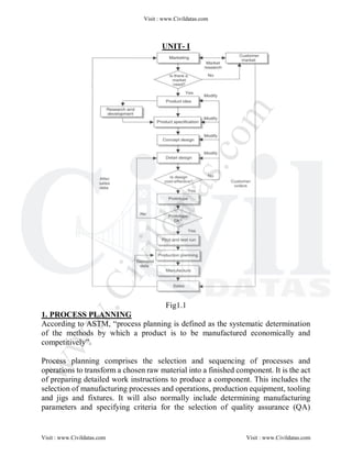
  • 1. UNIT- I Fig1.1 1. PROCESS PLANNING According to ASTM, ―process planning is defined as the systematic determination of the methods by which a product is to be manufactured economically and competitively‖. Process planning comprises the selection and sequencing of processes and operations to transform a chosen raw material into a finished component. It is the act of preparing detailed work instructions to produce a component. This includes the selection of manufacturing processes and operations, production equipment, tooling and jigs and fixtures. It will also normally include determining manufacturing parameters and specifying criteria for the selection of quality assurance (QA) Visit : www.Civildatas.com Visit : www.Civildatas.com Visit : www.Civildatas.com w w w . C i v i l d a t a s . c o m
  • 2. methods to ensure product quality. 1.1 Process planning the design/manufacture interface Fig 1.2 Main functions involved in product design and manufacture There are various functions within a manufacturing Organization. In terms of the successful product design and manufacture, there are three major functions involved, namely marketing and sales, design and manufacturing in fig 1.2. The numerous tasks undertaken by these functions in the design and manufacture of a product traditionally occur in a sequential manner. Generally, marketing is responsible for assessing the current market trends and needs and generating new product ideas. Also based on the market assessment, marketing is responsible for generating specifications for the further development of existing products. The role of sales is to generate interest in the products being manufactured and obtain firm orders. The design function will take the product ideas and specifications generated by marketing and provide a detailed specification of all the components and Visit : www.Civildatas.com Visit : www.Civildatas.com Visit : www.Civildatas.com w w w . C i v i l d a t a s . c o m
  • 3. sub-assemblies for the finished product. This will include all detail drawings, assembly drawings and bills of materials. Very often, a prototype of the product will be developed to help validate the design and establish which manufacturing facilities are required. The product and process requirements generated at the design and development stage are then passed to the manufacturing function. These will be used to prepare the detailed work instructions required to manufacture the product. These will then be passed to the manufacturing facility for execution. Therefore, although the design and manufacturing functions are separated, the process planning activity links them as shown in fig 1.3. Thus, process planning is the design/ manufacture interface in this sequential approach. This sequential approach to the design and manufacture of products has relied on there being a long product life cycle, that is, a stable demand for the product over a long period of time. However, in today's highly competitive global market, this is very often not the case. Therefore, manufacturing organizations have had to consider ways of compressing the time taken to design and manufacture products or the time to market as it is also known. Some have focused on the implementation of organizational change to achieve shorter times to market using matrix-based structures and encouraging all functions or departments to contribute to the development, design and manufacture of their products. This cooperative approach, based on the use of cross-functional teams, is known as simultaneous or concurrent engineering. Fig 1.3 Process planning - the design~manufacture interface The functions of such cross-functional teams include Visit : www.Civildatas.com Visit : www.Civildatas.com Visit : www.Civildatas.com w w w . C i v i l d a t a s . c o m
  • 4.  ensuring all team members understand enough about the product functions to be able to contribute to the design decisions;  determining the appropriate design and manufacturing methods to use;  relating all product functions to manufacturing methods. 1.3 Process planning activities 1. Drawing interpretation The first step in preparing the process plan for any component or product is to consult the engineering drawings. The drawing of the component under consideration will contain a variety of information which can help assess the processing requirements. The interpretation of the drawing will include assessing the part geometry, dimensions and associated tolerances, geometric tolerances, surface finish specifications, the material specification and the number of parts required. From this interpretation, the critical processing factors can be identified and give some indication of candidate manufacturing processes. For example, all processes and production equipment will have an economic batch quantity, that is, the batch size with which the process or production equipment becomes economically viable to use. Therefore, the number of parts required would eliminate certain processes and production equipment from the list of possible candidate processes while indicating the suitability of others. 2. Material evaluation and process selection Although the design engineer specifies the material to be used, the process planner will, on occasion, have to enter into a meaningful dialogue with the design engineer about the materials specified, based on the availability of manufacturing processes. Therefore, a thorough knowledge of the materials used in manufacturing is essential for effective process planning. This is because every material has different properties and, based on these, will be more suited to particular processes than others. For example, brittle materials are more suited to casting or material removal processes. On the other hand, they are not well suited for use with forming processes. Also, some materials undergo changes in properties during processing and therefore due consideration must be given to this fact. Finally, it is the job of the manufacturing engineer to specify the raw material billet form for the component. This will include the size and any special requirements for the raw materials, for example, heat treatment. Knowledge of material properties is essential to carry out this task, again because some materials undergo changes in their properties during Visit : www.Civildatas.com Visit : www.Civildatas.com Visit : www.Civildatas.com w w w . C i v i l d a t a s . c o m
  • 5. processing. For example, during forging a material may undergo dynamic loading and it is important to know how it will react to this sudden loading. Therefore, it is important to know about the material's impact resistance or toughness, as it is also known. Based on the drawing interpretation and the materials evaluation, a shortlist of candidate processes can be drawn up. Using some general rules for process selection and criteria such as material form, component size and weight, economic considerations, dimensional and geometric accuracy, surface finish specification, batch size and production rate, the shortlist can be evaluated further and a final selection of processes and operations identified. 3. Selection of machines and tooling Once the process planner has determined which processes are being used, the specific production equipment required for this must be selected. Typical factors to be considered include the component size and weight, the physical size and construction of the machine, and the power and torque of the machine. Another factor to be considered is the number and type of tools available for the machine under consideration. Once the equipment decision has been made, the specific tooling for each operation must be identified. Successful processing of a component relies heavily on the selection of appropriate tools, particularly for machining. This should be eased by the fact that available tooling should be a factor in the selection of the machine in the first instance. There are various factors that will be considered in selecting an appropriate tool including work piece material, type of cut, tool material, machining data and quality/capability requirements. For example, all processes and production equipment have an inherent capability in terms of surface finish. Thus, any process or production equipment that can't meet the surface finish specification would be discounted at an early stage of the selection process. 4. Setting process parameters Once the machines and tooling have been selected, specific parameters must be established for each operation for each machine. These include calculating appropriate feeds, speeds and depth of cut for each tool for each operation. It is also normal to calculate the time taken for each operation based on the part geometry and the speeds and feeds employed. Times taken for non-value added tasks, such as setting and handling, are also established. This enables the total time taken for the job to be compiled. A major part of this task will be the use of reference materials such as machine manufacturer's data and tool manufacturer's data. Visit : www.Civildatas.com Visit : www.Civildatas.com Visit : www.Civildatas.com w w w . C i v i l d a t a s . c o m
  • 6. 5. Work holding devices In the context of this book, work holding devices are classified into two categories. These are general-purpose work holders, which include the likes of chucks and collets, and specialist work holders, which are taken to mean jigs and fixtures. From the drawing interpretation, the process planner identifies any general location and restraint requirements and any critical location and restraint requirements. The general requirements will be based on any dimensional and geometric tolerances specified in the drawing, while the critical requirements will be based on any instances of coupled dimensional and geometric tolerances. Having identified the need for a jig or fixture for a particular operation and identified the location and clamping requirements, this data will generally be passed to a specialist tool designer. Based on these requirements, the tool designer will produce the detail drawings and a general arrangement drawing of the workholding device to be manufactured. 6. Selecting quality assurance methods The critical processing factors such as dimensional and geometric tolerances and surface finish specifications will have been identified during the drawing interpretation. It is the job of the process planner to specify the inspection criteria for all these critical processing factors as all manufacturing processes have some degree of inherent variability. In some cases, the process planner might be responsible for specifying the tools and techniques to be employed to ensure adherence to specification. However, more commonly the inspection criteria will be passed to a Quality Engineer who decides which tools and techniques are most appropriate. Finally, it is important to strike the balance between ensuring the product quality and avoiding unnecessary checking. The overuse of QA methods and inspection will add to the processing time which, in turn, will add to the manufacturing costs. 7. Costing The process planner is also tasked with estimating the costs of the process plan. This means estimating the manufacturing costs of producing a component or product based on the available cost and time data. This will be used to determine the unit cost and the profitability of the product. Cost data will also be used to formulate the process plan itself. Through establishing relationships between cost and volume, decisions can be made about what material to use, the manufacturing processes to be used, the batch size to be employed and whether to make or buy a product or component. Furthermore, relative cost data for materials and processes is used to help make process planning decisions. Visit : www.Civildatas.com Visit : www.Civildatas.com Visit : www.Civildatas.com w w w . C i v i l d a t a s . c o m
  • 7. Preparing the process planning documentation There are two documents involved in the preparation of the process plans. These are: 1. routing sheets; 2. Operations list. 1. Routing sheets The routing sheet, as its name suggests, specifies the route the raw material follows through the manufacturing environment. It usually lists the production equipment and tooling to be used. It is normal practice for the routing sheet to follow the material through the manufacturing shop floor providing 'travel' information for the operators. As stated it isquite often in the shop only a routing sheet will be used with the fine details of production left to the highly skilled operators employed in such an environment. Fig1.4 Route sheet 2. Operations list Once the routing of a component has been established, the detailed plan for every operation can be prepared using an operations list. This specifies in more detail each individual operation. It is usual for an operations list to be prepared for each workstation listed on the routing sheet, although it may sometimes cover a group of machines in a work cell. Although the content of an operations sheet will vary from organization to organization, it will typically include details of tooling (including Visit : www.Civildatas.com Visit : www.Civildatas.com Visit : www.Civildatas.com w w w . C i v i l d a t a s . c o m
  • 8. work holding devices), feeds and speeds, set-up and operation times. Fig1.5 operations sheet Miscellaneous documents In some companies, the total process planning package may include further documentation. For example, the calculations for the speeds and feeds detailed in the operations list may be detailed in a speeds and feeds calculation sheet as illustrated in Fig. 1.6. It can also be the case that further details of the tooling specified in the operations list is detailed in a tooling list, an example of which is illustrated in Fig. 1.7. Finally, it is important to note that in some companies a single process planning document may be used which is a combination of the routing sheet and the operations list. From the brief descriptions given above, it can be seen that the process plan provides the complete work instructions required for the manufacture of a component or product. Consequently, these instructions will affect the cost, quality and production rate of the component or product. Visit : www.Civildatas.com Visit : www.Civildatas.com Visit : www.Civildatas.com w w w . C i v i l d a t a s . c o m
  • 9. Fig. 1.6 speeds/feeds calculation sheet Visit : www.Civildatas.com Visit : www.Civildatas.com Visit : www.Civildatas.com w w w . C i v i l d a t a s . c o m
  • 10. Fig. 1.6 Tooling list Table1.1 Process chart symbols Visit : www.Civildatas.com Visit : www.Civildatas.com Visit : www.Civildatas.com w w w . C i v i l d a t a s . c o m
  • 11. Fig 1.7 Example of a flow process chart 1.4 Inputs and outputs for Process planning Fig 1.8 Inputs and outputs for process planning Visit : www.Civildatas.com Visit : www.Civildatas.com Visit : www.Civildatas.com w w w . C i v i l d a t a s . c o m
  • 12. 1.5 Process planning methods Traditional approach He looks at the drawing and uses his experience of manufacturing methods, combined with knowledge of the types of resource available; in some cases previously developed plan for a similar part forms the basis of the new plan. For each element of each operation, he refers to manuals to ascertain the company's recommended tools, feeds and speeds for the particular material on the selected machine. Also using manuals, the planned times for all the handling and machining elements involved in the process. Workbook approach This is considered a more efficient approach to process planning. It involves developing workbooks of pre-determined sequences of operations for given types of workpieces. After having carried out the drawing interpretation and identified the manufacturing processes required, the pre-determined sequence of operations can be selected from the workbook and incorporated into the process plan. Advantages The only real advantages of manual process planning are that it is a low-cost task and is flexible, in terms that the system can be changed easily. Disadvantages 1. Excessive clerical content 2. Lack of consistency in planning 3. Late design modifications 4. Changing technology Visit : www.Civildatas.com Visit : www.Civildatas.com Visit : www.Civildatas.com w w w . C i v i l d a t a s . c o m
  • 13. Computer Aided Process Planning Need for process planning (advantages) 1. Process rationalization and standardisation 2. Productivity improvement 3. Product cost reduction 4. Elimation of human error 5. Reduction in time, clerical and paper work 6. Improved legibility 7. Faster response to engineering changes 8. Incorporation of other application programs Variant CAPP system Visit : www.Civildatas.com Visit : www.Civildatas.com Visit : www.Civildatas.com w w w . C i v i l d a t a s . c o m
  • 14. This approach to CAPP is similar to the manual approach as it retrieves a standard plan and modifies it to suit for a given part. The standard plan is usually for a composite part that incorporates all the features for a particular group or family of parts. The parts are usually grouped according to how they are made using a GT classification and coding system. The process plan for the part under consideration is compiled by retrieving those parts of the standard plan that are relevant. Thus, the variant approach is also known as the retrieval method. Although popular in industry due to their relative ease of implementation and use, the major disadvantage of variant systems is that plans can be developed only for parts that have previously been classified as one of the part families. Generative Method of Process Planning (Generative CAPP System) The second method of computerized process planning is the generative method. In this method the computer uses the stored manufacturing and design data to generate a complete list of all possible process plans that could be used to manufacture the current part. It then exhaustively searches this list for the one which optimizes the cost function. This method always yields the optimum process plan for manufacturing a particular part. However, it has a very high cost in terms of time and computer processing expenses. The computations required to provide even a single process plan for an arbitrary part design can be enormously complex. To repeat this for every feasible process plan or a part can become very costly. This approach of process planning is also known as Generative CAPP System. Both the approaches viz. Variant (or retrieval) method of process planning and Generative method of process planning involves a systematic development of Code Numbers using Group Technology concepts and principles for the design and manufacture of the part. Both of these methods of computerized process planning can be enhanced through the application of AI (Artificial Intelligence) in the form of expert systems. 1.6 Drawing Interpretation Drawing Interpretation is to identify the relevant drawing information that helps the process planner by identifying the critical processing factors.  Appropriate supplementary information from the drawing to aid the process planning;  Identify and interpret dimensional information from the drawing;  Identify and interpret geometric information from the drawing;  Identify the critical processing factors for the component from the dimensional and geometric information. Just as raw material is the 'lifeblood' of manufacturing, information is the 'lifeblood' of design (Rhodes and Smith, 1987). Throughout the design process, from marketing to Visit : www.Civildatas.com Visit : www.Civildatas.com Visit : www.Civildatas.com w w w . C i v i l d a t a s . c o m
  • 15. manufacturing, various types of information is sent and received by numerous internal and external sources. In terms of process planning, the most important stage is the detail design. The output of the detail design is a complete description of the product in written and/or graphical form. The main thrust of this output will be the engineering drawings. These should contain all the information required to convey the design representation and are therefore a major input to the process planning activity. In engineering, the drawing is the most common form of communication and is accepted as a universal language. There are several types of drawings used in industry. These are (Parker, 1984):  Detail drawings;  Assembly drawings;  Combined drawings. Detail drawings contain all the information required to manufacture the item or items represented. This information will include all dimensions, tolerances, surface finish specifications, and material specifications. There are two different types of detail drawing. These are:  Single-part drawings;  Collective drawings. A single-part drawing should show all the information required to completely define the manufacture of a single item. This will include the form, dimensions, tolerances, material, special treatments, surface finishes, etc. It should be noted that a drawing might consist of more than one sheet as illustrated in Fig.3.2. There are also collective single-part drawings. These drawings show essentially similar parts where only one or more details differ from the rest. These are used for standard parts such as nuts, bolts, washers, etc. as illustrated in Fig. 3.3. Due to the nature of the information in detail drawings, they are of obvious use for process planning. Visit : www.Civildatas.com Visit : www.Civildatas.com Visit : www.Civildatas.com w w w . C i v i l d a t a s . c o m
  • 16. Visit : www.Civildatas.com Visit : www.Civildatas.com Visit : www.Civildatas.com w w w . C i v i l d a t a s . c o m
  • 17. Visit : www.Civildatas.com Visit : www.Civildatas.com Visit : www.Civildatas.com w w w . C i v i l d a t a s . c o m
  • 18. ASSEMBLY DRAWINGS Assembly drawings contain all the information required to assemble two or more parts together. Normally, there will be no dimensions on an assembly drawing. However, in some instances some dimensions that might be required for assembly may be included. There are three types of assembly drawings:  Single-part assembly drawings;  Collective assembly drawings;  Arrangement drawings. A single-part assembly drawing seems to be a contradiction in terms as an assembly drawing by definition contains two or more parts. However, what this actually means is that it contains the information to build a single sub-assembly or assembly. An assembly drawing should show all the necessary information to be able to assemble a product from a number of items. Information about the items is listed in a parts list that may well be separated from the actual drawing. Each item on the assembly drawing should have an identification number. An example of control handle assembly is illustrated in Fig 3.4. A collective assembly drawing shows a number of products that are assembled from the same or similar parts, the resultant assemblies only differing slightly from each other. Examples Visit : www.Civildatas.com Visit : www.Civildatas.com Visit : www.Civildatas.com w w w . C i v i l d a t a s . c o m
  • 19. include die sets differing in size and gearboxes with different ratios. Fig. 3.5 shows a typical example of a standard coupler, which actually has a few dimensions to aid assembly. An arrangement drawing, also sometimes referred to as a general arrangement drawing, is an assembly drawing which shows the complete product. This is in effect an assembly drawing of the assemblies or sub-assemblies as they are called in some cases. It contains all the information required to arrange the assemblies together, including any functional features of the product. An example of a general arrangement of a jig is shown in Fig. 3.6. Regardless of the type of assembly drawing, they are not used to develop process plans for the manufacture of either single parts of or groups of similar parts. However, they are used to prepare assembly plans for sub-assemblies, assemblies and complete products from a number of parts. Visit : www.Civildatas.com Visit : www.Civildatas.com Visit : www.Civildatas.com w w w . C i v i l d a t a s . c o m
  • 20. Visit : www.Civildatas.com Visit : www.Civildatas.com Visit : www.Civildatas.com w w w . C i v i l d a t a s . c o m
  • 21. COMBINED DRAWINGS A combined drawing shows an assembly with parts list and the details of these parts on one drawing as shown in Fig. 3.8. The individual parts need not be given special identification numbers or separate drawing numbers when using combined drawings. Visit : www.Civildatas.com Visit : www.Civildatas.com Visit : www.Civildatas.com w w w . C i v i l d a t a s . c o m
  • 22. Orthographic projection Although there are several types of drawings commonly employed in engineering, they are all usually multi-view drawings (Chang and Wysk, 1985). This means that they have two or three views of the part or assembly being represented. These views will usually be a view of the front (a front elevation), the top (a plan) and the side (a side elevation). This method of detailing a three-dimensional object on paper, which is, of course, a two-dimensional plane surface, is known as orthographic projection. To be able to fully represent a three-dimensional object using orthographic projection requires at least two planes of projection. These two planes are known as the horizontal plane (HP) and the vertical plane (VP). The intersection of these two planes forms perpendicular quadrants know angles as illustrated in Fig. 3.9. There are six basic rules that govern the use of orthographic projection (Hart, 1970):  The angles are designated as shown in Fig. 3.9 and the object is situated in the first angle.  The lines of sight are parallel and at right angles to the project planes.  The object is viewed from the top and front positions shown regardless of the quadrant it is situated in.  The horizontal plane can be rotated about the XY intersection until it coincides with the vertical plane.  The projection on the VP is known as the elevation.  The projection on the HP is known as the plan. and fourth Using these rules, the object situated in the first angle would be represented as illustrated in Fig. 3.10. This is known as first angle orthographic projection and this is commonly used in the Visit : www.Civildatas.com Visit : www.Civildatas.com Visit : www.Civildatas.com w w w . C i v i l d a t a s . c o m
  • 23. United Kingdom and Europe. However, if the object were situated in the third angle, the views of the object would be depicted as illustrated in Fig. 3.11. This is known as third angle orthographic projection and is commonly used in the North American continent. It should be noted that the views are identical in both instances and it is only the position of these that has changed. All engineering drawings will normally be in either first or third angle orthographic projection. This will be indicated on the drawing itself by one of the symbols shown in Fig. 3.12. Visit : www.Civildatas.com Visit : www.Civildatas.com Visit : www.Civildatas.com w w w . C i v i l d a t a s . c o m
  • 24. Visit : www.Civildatas.com Visit : www.Civildatas.com Visit : www.Civildatas.com w w w . C i v i l d a t a s . c o m
  • 25. SECTIONING As stated above, orthographic projection is the method of detailing a three dimensional object on a two-dimensional plane using a number of different views. However, for many components these views may not be sufficient to depict all details. This could be due to hidden or internal features that cannot be shown regardless of what view or views are taken. Although hidden details are generally illustrated by using broken lines, these can make a view look more complex. Therefore, in these instances a sectional view would be used. The sectional view is obtained by cutting the component in two using a designated cutting plane, which in many instances will be a centre line. The view is then drawn as if the part is cut in two and the hidden or internal details are shown. The surface that has been cut is shown using evenly spaced lines at 450 known as hatching. In the case where an assembly has been sectioned, each item sectioned will have hatching at alternate angles and sometimes have different spacing. A common derivative of this approach is the use of a half-section where both internal and external features are shown on a single view. An example of a sectional view is given in Fig. 3.13. Further examples of sectional views are shown in Figs 3.6-3.8. DIMENSIONS Visit : www.Civildatas.com Visit : www.Civildatas.com Visit : www.Civildatas.com w w w . C i v i l d a t a s . c o m
  • 26. The objective of providing an engineering drawing is to provide enough information for the part to be manufactured. Therefore, each geometric feature must have an associated size or dimension and the units employed clearly stated. If an engineering drawing has been properly dimensioned, then no calculation should be required to determine the size of any feature. Therefore, there must be sufficient dimensions to be able to manufacture the part. All dimensions can be classified as one of three types (Hadley, 1999):  Functional dimensions- those that influence or control the manner in which a part operates.  Non-functional parts- those that do not affect the way in which the part operates but can influence the efficiency of the part.  Auxiliary dimensions - those that are not related to the way the part operates but are required in order to manufacture the part. In terms of process planning, the size and the shape of the geometric features will have a major influence on the selection of manufacturing processes. IDENTIFYING USEFUL SUPPLEMENTARY INFORMATION Apart from the geometry, there will be various supplementary information on the drawing sheet, most of which will be textual information. Some of this will be basic information that will have no bearing on the process plan. This will include information such as the company name, drawing number and title, date, scale, projection symbol, copyright clauses, issue information and signatures (draughtsman, checker, etc.). However, there are certain items of additional information that will have some bearing on the process plan and these must be identified and used accordingly. These include:  Material and specification;  Notes on special material treatments;  Notes on surface finish;  General tolerances;  Keys to geometrical tolerances;  Notes on equivalent parts;  Notes on screw thread forms;  Tool references;  Gauge references;  Quantity to be produced;  Parts list (in the case of assembly drawings). The first five items listed above will have a major influence on the manufacturing processes to be used, based on the ability of the processes to meet the specifications for dimensional and geometrical accuracy and surface finish. Equally important to the selection of manufacturing processes, is the quantity to be produced. This is because most processes and production equipment have an economic batch quantity or a break-even quantity when compared to other processes. Therefore, although easily overlooked on a drawing, the above must be given as much attention as the drawing geometry itself due to their importance in the selection of manufacturing processes. MATERIAL AND SPECIFICATION A thorough knowledge of materials is essential for effective process planning. This is because the material used will have certain physical and mechanical properties that will make it more appropriate for use with some manufacturing processes and even completely unsuitable for Visit : www.Civildatas.com Visit : www.Civildatas.com Visit : www.Civildatas.com w w w . C i v i l d a t a s . c o m
  • 27. some processes. Therefore, the material specified will limit the manufacturing processes that can be used. Finally, the material to be used will usually be stated as a specification that will relate to a specific material. Therefore, familiarity of the appropriate material standards is essential in the first instance, to correctly identify the material and in the second instance, to enable suitable candidate processes to be identified. SPECIAL MATERIAL TREATMENTS All materials exhibit certain mechanical and physical properties. However, in certain cases, these properties might change due to the manufacturing processes used. In instances where this is the case, the material may have to undergo a special treatment to improve or restore certain properties that altered during processing. For example, some steels may lose some of their toughness during processing. In order to improve the toughness the steel may be tempered. This involves heating the metal to its specific temperature then cooling it at a controlled rate. Therefore, this must be considered in the process plan. EQUIVALENT PARTS (INTERCHANGEABILITY AND STANDARDIZATION) Modem manufacturing is based on three major concepts. These are mass manufacture, interchangeability and standardization. Of these concepts, both interchangeability and standardization influence the specification of equivalent parts. lnterchangeability The concept behind interchangeable manufacture is that parts, and in particular mating parts, are manufactured in a manner that allows any one of a batch of parts to be used with any other appropriate mating part in a sub-assembly or assembly. That is not to say that they are identical, but they are made within certain agreed tolerances. Thus, interchangeable manufacture requires (Black et al., 1996):  the permissible variation of each dimension to be agreed (i.e. dimensional tolerances);  the mating condition of each pair of mating parts to be agreed (i.e. limits and fits). Therefore, in essence, interchangeable manufacture is about making parts as near to identical as possible to allow then to function identically within a sub-assembly or assembly. Process planning is, in fact, one of three activities considered essential in the pursuit of interchangeable manufacture. Of the other two activities, the first to consider is the design of special jigs and tools to accommodate repeatability in manufacture. The final activity is the design of suitable limit gauges and gauging equipment to control the accuracy of manufacture. Standardization In order to pursue the goal of interchangeable manufacture, methods of standardization have been developed, such as those mentioned later in this chapter for screw thread forms and limits and fits. The use of standardization in manufacturing usually involves five key steps (Matthews, 1998):  Identifying and using preferred numbers and sizes;  Identifying which dimensions should be toleranced;  Setting the tolerance values;  Designing suitable measurement and inspection tools and procedures;  Specifying these requirements in the design specification. In recent years, the use of standard parts has increased dramatically. The use of standard parts has a number of distinct advantages over the use of unique parts. The first of these is that they are more widely available and should be of a known capability and reliability (Nicholas, 1998). Furthermore, standard parts will be cheaper, also due to their widespread use and Visit : www.Civildatas.com Visit : www.Civildatas.com Visit : www.Civildatas.com w w w . C i v i l d a t a s . c o m
  • 28. availability. Therefore, in the event of service and repair, replacements for standard parts should be easily sourced. Finally, as part of this use of standard parts, it may be that more than one part can be used and there may be equivalent parts that can be used. The standardization of parts may be based on part families. Many organizations may use Group Technology (GT) classification and coding as the means to formulate these part families. SCREW THREAD FORMS Many parts that will eventually form part of a sub-assembly or assembly will be joined by means of mechanical fasteners such as screws and/or nuts and bolts. Therefore, a thorough understanding of how these are represented in graphical and written terms is essential. Although there are many screw thread forms used in engineering (such as Whitworth and Unified), the most commonly used is the ISO metric screw thread. These can be manufactured as either coarse or fine pitch series threads. For the vast majority of engineering applications, coarse pitch threads will suffice. These are usually represented on an engineering drawing with an M prefix followed by a value indicating the external diameter in millimetres. For example, if a screw thread is designated as M5, it is a coarse pitch thread of 5 mm diameter. However, if a fine pitch thread is used, the M and associated diameter value will be followed by the pitch. For example, if a thread is designated as M5 x 0.5, it is a fine series pitch. Several of the standard combinations of pitch and diameter are given for both coarse and fine threads in Table 3.1. It should be noted that if a thread is stated with a pitch that is not a standard combination of pitch and diameter it is not a fine series pitch thread. For example, M5 x 0.35 is simply an ISO metric thread of pitch 0.35 mm, that is, it is a non-standard combination of diameter and pitch (Davies and Yarwood, 1986). Finally, tolerances of fit may also be added to the thread. For more details, the relevant standard should be consulted. TOOL REFERENCES When designing and detailing a part some design engineers might specify certain tools to produce particular features. Therefore, in terms of process planning it is essential that these can be Visit : www.Civildatas.com Visit : www.Civildatas.com Visit : www.Civildatas.com w w w . C i v i l d a t a s . c o m
  • 29. interpreted. In most instances, the appropriateness of the tool specified will also be considered in terms of the complete process plan. This is because the specification of a particular tool may limit the processes that can be employed. For example, a designer may specify that a hole is reamed to a specific surface finish and identify the specific tool to perform this operation. DIMENSIONAL TOLERANCES Although drawings are generally dimensioned without tolerances, in manufacturing engineering terms, the achievement of an exact dimension is a practical impossibility. However, as notes on general tolerances are usually included on the drawing. This usually takes the form of a general statement such as tolerances +_ 0.5 unless otherwise stated and this saves having a tolerance for every individual dimension. Therefore, only those dimensions that do not adhere to this general tolerance require a tolerance limit to be added to it. Therefore, the limits within which a dimension is acceptable can be included with that dimension. There are two basic methods used to indicate the limit of size on an individual dimension, although they do the same thing, that is, state the minimum and maximum size of a dimension. The first method directly states the upper and lower limit of the size (in that order) to the same accuracy. This is illustrated in Fig. 3.14. The second method states the size with a tolerance value, that is, the value it can be over or undersized. In cases where the over- and undersize are equal it will be as shown in Fig. 3.15. In cases where maximum and minimum sizes are different, they should be expressed to the same accuracy, except where a limit is zero. These are also illustrated in Fig. 3.15. Visit : www.Civildatas.com Visit : www.Civildatas.com Visit : www.Civildatas.com w w w . C i v i l d a t a s . c o m
  • 30. Finally, limits can be either unilateral or bilateral. In the first instance with a unilateral tolerance, the maximum and minimum sizes are both on the same side of the basic size, that is, both over or under the basic size. However, with a unilateral tolerance the maximum and minimum limits are above and below the basic size (Simmons and Maguire, 2001). Examples of both of these are illustrated in Fig. 3.16. LIMITS AND FITS The tolerances described above specify the acceptable upper and lower limits within which a size may vary. However, in addition to these tolerances the class of fit may be specified. There are two bases for systems of limits and fits and these are (Simmons and Maguire, 2001): Hole basis- in this system the shaft must fit the hole. This means the hole size remains constant while the shaft size varies according to the type of fit. This is usually the system of fits employed as it allows for economic manufacture. This is because a single tool can be used to produce the hole and the type of fit required can be varied by changing the limits of the shaft. Shaft basis- in this system the hole must fit the shaft. This means the shaft size remains constant while the hole size varies according to the type of fit. However, this is more expensive because a range of tools is required to produce the holes. However, this system might be employed Visit : www.Civildatas.com Visit : www.Civildatas.com Visit : www.Civildatas.com w w w . C i v i l d a t a s . c o m
  • 31. when a number of fits are required along a long shaft or when temperature can affect larger hole sizes. Regardless of the base of the system, the class of fit to which a part is manufactured will depend on its function within an assembly as described below. Considering the hole-based system (i.e. the shaft fits the hole) as this is more commonly used, there are three basic types of fit: Clearance fit- where the shaft is made smaller than the hole under all extremes of tolerance, that is, the upper size of the shaft is smaller than the lower size of the hole, allowing it to rotate within the hole. Typical applications of this type of fit are found in shaft bearings and where it is a requirement for one part to slide within another. Interference fit - where the shaft is made larger than the hole under all extremes of tolerance, that is, the lower size of the shaft is larger than the upper size of the hole, and pressure or heat will be used to mate the parts. This type of fit results in a permanent assembly and typical applications are found in press-fit bushes and couplings shrunk onto shafts after pre-heating. Transition fit- where a light interference fit is often used and the parts can be assembled and unassembled with the minimum of pressure. However, it should be noted that a transition fit may provide either a clearance or interference fit at extremes of the tolerances. Typical applications of this fit include fasteners such as keys, pins and parts fitted together for location purposes. The tolerances of the fit are usually indicated by indicating the permitted maximum and minimum sizes with the dimensions on the drawing, according to the aforementioned class of fit required. These indicate the limits of a size of a fit between mating parts, a series of which are defined in BS4500: ISO limits and fits. It uses a system of two complimentary elements, known as a fundamental deviation and a tolerance grade, to specify tolerances. A fundamental deviation is defined as the smallest permissible deviation, that is, that which is closest to the nominal size using the designate tolerance grade. Fundamental deviations for holes are designated using capital letters, while for shafts lower-case letters are used. According to this standard, there are 27 fundamental deviations for both holes and shafts from the nominal size. There are also 18 tolerance grades provided and they are designated with the letters IT, which stands for ISO series of tolerances, and they range from IT01, IT0, IT1, etc. up to IT16 as illustrated in Table 3.2. Used in conjunction letter code for the fundamental deviation, only the tolerance grade number is used, for example, H8. If a hole is dimensioned as 050 H8/f7, this means it is a hole-based system, that is, the shaft fits the hole. The H8 indicates that the hole deviation is +0.046 mm and 0. For the shaft, the f7 indicates that the upper tolerance is -0.03mm and the lower tolerance is -0.06mm. Visit : www.Civildatas.com Visit : www.Civildatas.com Visit : www.Civildatas.com w w w . C i v i l d a t a s . c o m
  • 32. Determining the fit of the hole is achieved by comparing the extremes of the shaft and the hole that is the largest shaft is compared with the smallest hole and the largest hole with the smallest shaft. The use of the above system is best illustrated through a worked example. Example: Using the example cited in previous section, that is, a hole is dimensioned as 050 H8/f 7, and the data charts in BS4500, determine the upper and lower limits, the extremes of fit and thus the type of fit for this combination of shaft and hole. As stated above, the H8 indicates that this is a hole-based system, that is, the shaft must fit the hole. Upper and lower limits Hole H8: Upper deviation = 0.046 mm. Upper limit = 50.046 mm Lower deviation = 0 mm. Lower limit = 50 mm Shaft f7: Upper deviation = -0.03 mm. Upper limit = 49.97 mm Lower deviation = -0.06 mm. Lower limit = 49.94 mm Extremes of fit Largest hole = 50.046 mm Smallest shaft = 49.94 mm Difference = 0.106 mm (clearance) Smallest hole = 50 mm Largest shaft = 49.97 mm Difference = 0.03 mm (clearance) Type of fit Using the above calculations, the type of fit is a clearance fit. This is because there is clearance at both extremes of tolerance as defined in Section above. Although the above limits and fits have been described in terms of holes and shafts, these are equally applicable to parts of square section and to sizes of length, height and depth of parts. Gauge references Dimensional tolerances and limits and fits on certain features must be employed carefully Visit : www.Civildatas.com Visit : www.Civildatas.com Visit : www.Civildatas.com w w w . C i v i l d a t a s . c o m
  • 33. for two main reasons. The first is that as the dimensional tolerances/limits become tighter there will be fewer manufacturing processes with the capability to produce the part, that is, there are greater limitations on the manufacturing processes that can be used. The other reason is simply that as the tolerances/limits become tighter the cost of manufacturing the part increases. In addition, these features must be checked to ensure that they conform to the specifications in the engineering drawing. This usually falls under the general heading of quality control that would determine the sampling system to be employed for inspection. The inspection will usually use a system of gauging to measure any toleranced dimensions. However, not all toleranced dimensions need be measured, as this would be time consuming and expensive due to the level of skill required to perform it, particularly for mass/flow manufacturing. Therefore, only a number of key toleranced dimensions which are indicative of the process accuracy will be measured (Matthews, 1998). A common application of gauging is the use of GO/NO-GO gauges. The idea is that the GO gauge must fit and the NO-GO must not fit for the feature to be within the specified tolerances. These are particularly useful for checking mating parts and threaded parts. Therefore, In a case where there are a number of key toleranced dimensions for which a system of gauging is already being employed, references may be made to this system on the engineering drawing. GEOMETRICAL TOLERANCES Symbols for geometrical forms and features Just as dimensional tolerances restrict size to certain limits, geometrical tolerances limit the shape of a component to certain limits. The symbols for these are illustrated in Table 3.3 and these are taken from BS EN ISO 7083: Geometrical tolerancing. Symbols for geometrical tolerancing, while Table 3.4 shows additional symbols that can be used in conjunction with the main geometrical symbols. These are used in an engineering drawing in a tolerance frame as shown in Fig. 3.17. This occurs when a feature is being toleranced with respect to two geometric forms or positions. 3.13.2 Description and interpretation of geometrical tolerances In effect, a geometrical tolerance limits the permissible variation of form, attitude or location of a feature (Kempster, 1984). It does so by defining a tolerance zone within which the feature must be contained. Although a full listing of geometrical tolerances is provided in BS EN ISO 1101: Technical drawings. Geometrical tolerancing, a list with a brief description of the tolerances is given below (Hawkes and Abinett, 1981) Visit : www.Civildatas.com Visit : www.Civildatas.com Visit : www.Civildatas.com w w w . C i v i l d a t a s . c o m
  • 34. Straightness - limits the amount of 'waviness' of a surface in two dimensions between two parallel straight lines set a specified distance apart (see Fig. 3.18a). Flatness - limits the amount of 'bumpiness' of a surface in three dimensions between two parallel Visit : www.Civildatas.com Visit : www.Civildatas.com Visit : www.Civildatas.com w w w . C i v i l d a t a s . c o m
  • 35. planes set a specified distance apart (see Fig. 3.18b). Roundness - limits the amount of ovality of a surface in three dimensions between concentric circles set a specified distance apart (see Fig. 3.18c). Cylindricity- limits the amount of ovality of a cylindrical cross-section and the 'bumpiness' along its length between two concentric cylinders set a specified distance apart (see Fig. 3.18d). Parallelism - limits the extent to which a surface is out of true between two parallel planes set a specified distance apart from the datum (see Fig. 3.18e). Squareness- limits the extent to which perpendicular surfaces are out of true between two parallel planes set a specified distance apart that are square to the chosen datum (see Fig. 3.18f). Angularity- limits the extent to which two surfaces at a stated angle may be out of true between two parallel planes set a specified distance apart that are true to the required angle and datum (see Fig. 3.18g). Concentricity- limits the extent to which a cylinder axis can vary within a cylinder of a specified diameter whose axis is in line with the chosen datum axis (see Fig. 3.18h). Symmetry - limits the extent to which the symmetrical axis of two planes is out of true between two parallel planes set a specified distance apart which are also symmetrical about the central datum axis (see Fig. 3.18i). Position (or true position) - limits the extent to which an axis may deviate from its stated position in three dimensions to lie within a cylinder of specified diameter whose axis is in the true position (see Fig. 3.18j). Visit : www.Civildatas.com Visit : www.Civildatas.com Visit : www.Civildatas.com w w w . C i v i l d a t a s . c o m
  • 36. Visit : www.Civildatas.com Visit : www.Civildatas.com Visit : www.Civildatas.com w w w . C i v i l d a t a s . c o m
  • 37. The best way to gain familiarity with the application and interpretation of these symbols is through examples. Examples of these tolerances are given in Fig. 3.18 as indicated above in the brief descriptions. SURFACE FINISH All manufacturing processes have an inherent ability to produce a range of surface finishes, sometimes also referred to as surface texture or surface roughness (although this actually refers to a specific type of surface irregularity). This is illustrated in Fig. 3.19, which was compiled from various sources (Hawkes and Abinett, 1984; Schey, 1987; Mair, 1993; Kalpakjian, 1995; Swift and Booker, 1997). Surface finish is defined as the depth of irregularities of a surface resulting from the manufacturing process used to produce it. The smaller the irregularity, the smoother the surface. There are three basic types of surface irregularities that can occur, and these are illustrated in Fig. 3.20. The first of these is a geometric or form irregularity, that is, the actual surface deviates from the geometric surface. These types of error have already been discussed in Section 3.13. Visit : www.Civildatas.com Visit : www.Civildatas.com Visit : www.Civildatas.com w w w . C i v i l d a t a s . c o m
  • 38. However, two further irregularities can also occur that tend to form the surface texture. The first of these is known as waviness and is generally caused by machine vibration or heat. This is also the larger of the two irregularities. The last irregularity is superimposed on the waviness and is known as roughness. These irregularities are inherent in the manufacturing process itself. The most commonly used method of indicating the surface finish is to use the average depth of surface irregularity resulting from the use of a manufacturing process. This is termed the Ra value and is measured in micrometres (μm) or microinches. When specifying a value, it should be selected from the ISO range of preferred values for surface finish as shown in Table 3.5 and can be indicated by the corresponding N-value. The table also shows the equivalent N-value in microinches, which are still widely used in the United States. When indicating a surface finish on a drawing, machining symbols are used. A variety of information can be included with the symbol:  the manufacturing process or treatment to be used; Visit : www.Civildatas.com Visit : www.Civildatas.com Visit : www.Civildatas.com w w w . C i v i l d a t a s . c o m
  • 39.  the sampling length (the length over which the surface finish has to be measured);  the direction of lay (the direction of cutting);  the machining allowance (how much material is to be left for removal by machining);  the surface finish required of the machining process. This information is used with the machining symbol as shown in Fig. 3.21 and it should be noted that only some of this information may be used and not necessarily all of it. However, there are three basic variations of this symbol as illustrated in Table 3.6. The first of these indicates the surface finish required and that the surface must be machined, in this case to a surface finish of n Ixm. The second symbol again indicates the surface finish required but this time machining is not mandatory, that is, any process capable of producing the specified surface finish can be used. For example, some casting processes have the capability to provide the specified surface finish for a feature without secondary processing, i.e., machining. Finally, the third variation of this symbol again states the surface finish required. However, if this symbol is used then the surface must not be machined. For example, machining a surface might be prohibited if other surfaces or features might possibly be damaged through either the work holding or the machining itself. Visit : www.Civildatas.com Visit : www.Civildatas.com Visit : www.Civildatas.com w w w . C i v i l d a t a s . c o m
  • 40. IDENTIFYING THE CRITICAL PROCESSING FACTORS The identification of the critical processing factors is the first step towards identifying the appropriate manufacturing processes to be employed. The drawing interpretation forms the basis for this and there are three distinct analysis and outputs from this. These are the geometry analysis, the manufacturing information analysis and the material evaluation. These analyses will include considering the geometric shape, dimensions and associated tolerances, geometric tolerances, surface finish specifications, the raw material size and the number of parts required. Particular attention should be paid to instances where there are combinations of dimensional tolerances and geometrical tolerances and/or surface finish specifications. The correlation of the output from these analyses allows the critical processing factors to be formulated. These are a list of requirements that the manufacturing process or processes selected must meet. Visit : www.Civildatas.com Visit : www.Civildatas.com Visit : www.Civildatas.com w w w . C i v i l d a t a s . c o m
  • 41. 1.7 Material Evaluation Manufacturing was defined in terms of transforming raw materials into a product. The selection of a specific material for a particular part or product is an important part of the design and manufacture cycle. It is the responsibility of the design function, not only to design a product that meets the specific need, but also to select the correct material for the part or product. However, once specified, the selection of a specific material ultimately limits the manufacturing processes that can be used. Four important factors influence the use of materials in manufacturing are  the product design must meet the specified need;  materials with appropriate properties must be selected;  based on both of the above, suitable manufacturing processes must be selected; Aims and objectives  To identify and describe the common materials used for manufacture;  To identify and describe the main properties of materials;  To identify and describe common material selection processes;  To identify and describe the common processes used for manufacture;  To carry out an overall evaluation of the selection of materials for manufacture in terms of processes;  select suitable processes for a given part/product based on the critical  Processing factors identified during the drawing interpretation. 1.7.1 Basic classification of Materials (fig 1.7.1) + Visit : www.Civildatas.com Visit : www.Civildatas.com Visit : www.Civildatas.com w w w . C i v i l d a t a s . c o m
  • 42. 1.7.2 General mechanical and physical material properties 1.7.3 Material selection process and methods Material selection process The selection of an appropriate material or materials for a product design is a difficult and complex task. However, regardless of the level of difficulty or omplexity, two distinct approaches arise for the materials selection process:  the design and development of a new product;  the modification of an existing product. Visit : www.Civildatas.com Visit : www.Civildatas.com Visit : www.Civildatas.com w w w . C i v i l d a t a s . c o m
  • 43. The most thorough approach to any materials selection problem is to view it as the design and development of a new product. There are five basic steps that can be followed for this approach (Dieter, 2000): 1. Specify the performance parameters of the design and translate these into the required material properties, for example, strength, hardness, etc. taking into account the cost and availability of materials. 2. Specify the manufacturing considerations such as the quantity/ batch size; size, weight and complexity of the part; dimensional and geometrical accuracy required, the surface finish required, any quality requirements and the overall manufacturability of the material. 3. Draw up a shortlist of candidate materials from the largest possible database of materials deemed suitable for the application. 4. Evaluate the candidate materials in more detail. Compare each, based on product performance, cost, availability and manufacturability. The result of this evaluation should be the selection of a single material. 5. Develop design data and/or a design specification for the chosen material. The second approach of modifying an existing product is usually carried out to reduce costs and/or improve quality. In terms of the material selection process, this is often referred to as materials substitution. However, it should be noted that the manufacturing processes associated with the materials are also evaluated to optimize the material substitution. Again, there are five basic steps to the material selection process: 1. Evaluate the current product in terms of the materials performance, manufacturing process requirements and cost. 2. Identify which characteristics have to be improved for enhanced product Performance. 3. Search for alternative materials and/or manufacturing routes. 4. Compile a shortlist of materials and manufacturing routes. Evaluate each in terms of the cost of manufactured parts. 5. Evaluate the results of Step 4 and employ the best alternative. The third approach, which is similar, called as the case-history method. The assumption is that something similar has been previously manufactured successfully and that the combination of materials and processes can be used again. Although a useful approach, even the slightest difference in product performance requirements can render the previous material selection useless. The other disadvantage of this technique is that developments in technology, materials and processes tend to be overlooked. Visit : www.Civildatas.com Visit : www.Civildatas.com Visit : www.Civildatas.com w w w . C i v i l d a t a s . c o m
  • 44. Material selection Methods Several methods have been developed for material selection problems, some not only applicable to material selection but also any design selection procedure. Although no one method is accepted as the standard approach, there are a number of commonly used methods.  selection with computer-aided databases;  performance indices;  decision matrices;  selection with expert systems;  value analysis (particularly for materials substitution);  failure analysis;  cost-benefit analysis. 1.7.4 Material evaluation method one of the prime considerations for the manufacturing engineer or process planner is the shapes or features required. Any number of processes can be used to produce a particular shape as given in the following table Visit : www.Civildatas.com Visit : www.Civildatas.com Visit : www.Civildatas.com w w w . C i v i l d a t a s . c o m
  • 45. Visit : www.Civildatas.com Visit : www.Civildatas.com Visit : www.Civildatas.com w w w . C i v i l d a t a s . c o m
  • 46. identified based on the shapes and features, they should be evaluated in terms of dimensional and geometrical tolerance requirements, surface finish requirements, component size, material selected, relative processing costs and the quantity required (some of which are included in the above table. It is also important to remember that the processing will nearly always affect the properties of the material. For example, ductility and hardness will be relevant properties to consider if the material is to be hardened by heat treatment. The process planner merely evaluates the result of the material selection process, that is, the material selected in terms of how the part should be manufactured. This evaluation should focus on three main areas 1. shape or geometry considerations; 2. material property requirements; 3. manufacturing considerations Visit : www.Civildatas.com Visit : www.Civildatas.com Visit : www.Civildatas.com w w w . C i v i l d a t a s . c o m
  • 47. Shape or geometry considerations This particular consideration affects the manufacturing process. Although most of these considerations are obvious, some can be more complex than first imagined. Typical considerations are: 1. What is the relative size of the component? 2. How complex is the shape? Is it symmetrical at all? Uniform cross-sections? Will it be more than one piece? 3. Are there enough dimensions to enable manufacture? 4. Are there any dimensional tolerances outside the general tolerance requirements? 5. How does this part mate in a sub-assembly or assembly? 6. What are the surface finish requirements? 7. Have allowances been made for wear during service? 8. Are there any minor design modifications that can significantly improve manufacturability, that is, design for manufacture? Visit : www.Civildatas.com Visit : www.Civildatas.com Visit : www.Civildatas.com w w w . C i v i l d a t a s . c o m
  • 48. All of the above should have been considered during the drawing Interpretation to help identify the critical processing factors. A useful tool in assessing the geometry in terms of manufacturing processes is the geometry classification matrix as shown below. Finally, the material and shape/geometry should also be assessed in terms of the raw material or billet form. Raw materials come in many shapes and forms for many different processes as shown. In many cases, the forming of the billet may simply be a case of cutting the material to the required size from stock material. However, for complex geometry the billet may be formed using manufacturing processes from the casting and forming/shaping categories. Material property requirements This is a much more complex task and can be split into three distinct considerations namely:  mechanical properties;  physical properties;  service environment. Visit : www.Civildatas.com Visit : www.Civildatas.com Visit : www.Civildatas.com w w w . C i v i l d a t a s . c o m
  • 49. Mechanical properties 1. Are there any static loading needs with regards to particular processes? 2. Is failure likely during manufacture and, if so, how? 3. Is there the likelihood of impact loading? Type and magnitude? 4. Is there the likelihood of cyclic loading? Type, magnitude and frequency? 5. Is wear resistance needed? Where? How much? 6. Is there a temperature range within which the properties are stable? 7. How much can the material deform and still function properly? Physical properties 1. Will processing affect electrical property requirements? 2. Will processing affect magnetic property requirements? 3. Will processing affect thermal property requirements? 4. Is weight a significant factor? 5. Is appearance a significant factor? Service requirements 1. What is the range of operating temperatures and rate of temperature change? 2. What is the most severe environment anticipated with respect to corrosion and deterioration of material properties? 3. What is the desired service lifetime of the product? 4. What is the anticipated maintenance for this component? 5. What is the potential liability if the product should fail? 6. Should the product be manufactured with recycling in mind? Manufacturing considerations A final concern is to determine the various factors that would influence the potential manufacturing processes. These include: 1. Have standard components and parts been specified wherever possible? 2. Has the ease of manufacture of the design been considered? 3. How many components have to be made and at what rate? 4. What is the minimum and maximum section thickness? 5. What is the desired level of quality compared to similar products on the market? 6. What are the anticipated quality control and inspection requirements? 7. Are there any special considerations to be made for assembly? It is important that evaluation of the selected material is as thorough as possible. The above factors cover all the main considerations for the process plan. However, it is not intended to be exhaustive and it should be recognized that every product and/or part might have some unique requirement not considered above. Visit : www.Civildatas.com Visit : www.Civildatas.com Visit : www.Civildatas.com w w w . C i v i l d a t a s . c o m
  • 50. Finally, another useful tool in identifying candidate processes, in terms of the material selected, is the PRIMA selection matrix developed by Swift and Booker. Visit : www.Civildatas.com Visit : www.Civildatas.com Visit : www.Civildatas.com www.Civildatas.com
  • 51. 1.7.5 General classification of manufacturing processes 4.12 Process selection 4.12.1 Factors in process selection Regardless of the material selection process employed (as detailed in Section 4.9), the result will be the selection of a suitable material or materials. The material itself will limit the manufacturing processes that can be used, as not all materials are suitable for all processes. For example, when considering joining processes, cast iron cannot be used for resistance welding. However, there are a number of factors common to both the material and process selection decisions:  the number of components to be made;  the component size;  the component weight;  the precision required;  the surface finish and appearance required. All of these factors have already been considered at the material evaluation stage. However, In terms of the material evaluation for process planning, the focus will be firmly on 'manufacturability' or 'processability', as it is also known. This is defined as the ability of a material to be worked or shaped into the finished component (Farag, 1979) and is sometimes referred to as 'workability'. Thus terms such as 'weldability', 'castability', 'formability', 'machinability' are used to describe how easily the material can be used for specific processes. The workability will also have a significant influence on the quality of the part, where quality is defined by three factors (Dieter, 1988):  freedom from defects;  surface finish;  dimensional accuracy and tolerances. Thus, the combination of material and process will have a significant bearing on the quality of the part and thus the process selected must be appropriate for the material. Visit : www.Civildatas.com Visit : www.Civildatas.com Visit : www.Civildatas.com w w w . C i v i l d a t a s . c o m
  • 52. Finally, apart from all of the above technical factors, there are also the economic factors to be considered. Many of the decisions to be made in the design and manufacture of a product will be influenced by the costs involved. Therefore, the total cost of the product must be considered as early as possible. Other economic considerations will be based on the quantity required in terms of the production volume, the production rate and the economic batch size. This aspect of the process planning activity will be considered 1.7.6 General guidelines for process selection Numerous criteria can be used in the selection of manufacturing processes. These could include such as material form, component size and weight, Visit : www.Civildatas.com Visit : www.Civildatas.com Visit : www.Civildatas.com w w w . C i v i l d a t a s . c o m
  • 53. economic considerations, dimensional and geometric accuracy, surface finish specification, batch size and production rate as already mentioned. In many instances, the technology used to manufacture a product may be so well established that the choice is obvious. Regardless of the factors, some general guidelines can be applied for the selection of manufacturing processes. 1. Select a process capable of providing the specified dimensional/ geometric accuracy and surface finish. 2. Specify the widest possible tolerances and surface finish variation for products to allow the widest possible choice of manufacturing processes. 3. Use prototypes as much as possible, taking into consideration the variation in performance of methods used to manufacture a one-off compared with volume manufacturing. 4. Carry out a detailed comparison of candidate processes early in the design process, paying particular attention to the variation in assembly costs for different processes. Two useful tools in identifying candidate processes are the geometry classification matrix and the PR/MA selection matrix 1.7.7 Process selection method As can be seen from the coverage in this chapter so far, process selection is a complex activity. Therefore, a process selection method is required to help make the approach to process selection more systematic. The process selection method was developed to help undergraduates grasp the complexity of process selection while providing them with a systematic method to follow. Two basic assumptions are made in using this method. These are: 1. the material has been selected first, as opposed to manufacturing processes first, and specified at the design stage; 2. all the information contained within the design documents, that is, drawings, parts lists, etc. is comprehensive and that all information required for manufacturing can be derived during the drawing interpretation. Visit : www.Civildatas.com Visit : www.Civildatas.com Visit : www.Civildatas.com w w w . C i v i l d a t a s . c o m
  • 54. There are four stages to this process selection method as follows: 1. Drawing interpretation As detailed in Chapter 3, the drawing interpretation forms the basis for the process selection. This analysis can be broken down into three distinct analysis and outputs. The first of these is the geometry analysis. Using the geometry classification matrix, a number of candidate processes can be identified based on the complexity of shape required. The size of the part will also be considered. The second analysis and output is that concerned with the manufacturing information in the design documents. This includes information such process parameters as the surface finish, dimensional and geometric tolerances, limits and fits, special treatments, gauge references and tooling references. The third and final analysis and output is that of the material Evaluation stage. This considers the material in terms of the desired geometry, the material properties and the manufacturing considerations. Using the PRIMA matrix, a number of further candidate processes can be identified. 2. Critical processing factors The combined output from the first stage must be correlated to identify the critical processing factors. In particular, the correlation of the candidate processes from the geometry analysis and the material evaluation may allow the list of candidate processes to be shortened using these factors. This is because they provide quantitative limits within which the candidate process must operate. 3. Consult process tables Using the correlated data from the previous stage, the candidate processes are compared by using the appropriate process selection table. In most cases, this approach will enable a clear-cut decision to be made using all the information gathered. However, in a case where more than one process can meet all the requirements, economic data such as labour, equipment and tooling costs, batch size and production rate, may provide further clarification. In some instances, a detailed cost comparison may have to be made between processes to help make a decision. Finally, in some instances the decision being made maybe whether to make or buy in a part/product where the process expertise is not available in-house. It should be noted that the use of costing methods should be incorporated as early as possible in the design and manufacture process. Visit : www.Civildatas.com Visit : www.Civildatas.com Visit : www.Civildatas.com w w w . C i v i l d a t a s . c o m
  • 55. 4. Identifying a process Using the data from the second stage, and if required a detailed economic analysis, a suitable process should be selected. If it is the case that one process is all that is required to make the part, then the process selection is complete. However, except in the case of the use of some primary processes, secondary processing is usually required. Therefore, in cases where further processing is required, the critical processing factors should be reconsidered and stage 3 repeated. Once all the required processes have been identified, the process selection is complete. Visit : www.Civildatas.com Visit : www.Civildatas.com Visit : www.Civildatas.com w w w . C i v i l d a t a s . c o m
  • 56. 1.8 Production Equipment and Tooling 1.8.1 Factors in equipment selection Although there is a huge amount of processing equipment, and variables of such equipment, the problem of selecting a suitable machine is easier than selecting a suitable process. In fact, with the process already selected, the range of machine tools to select from is already narrowed. Some of the factors used to select a suitable process will be used again to select a suitable machine, for example, surface finish and machine accuracy. These factors can be categorized as either technical or operational factors. Technical factors The focus of the technical factors is to ensure the machine tool selected is capable of producing the part to the required specification. The main factors considered are: Physical size - the machine tool must be of a sufficient size to cope with the dimensions of the workpiece and be physically able to carry out the desired processing. In addition, the structure of the machine must be able to cope with the weight of the workpiece. Machine accuracy- this refers specifically to the capability of the machines under consideration to be able to manufacture parts within the required dimensional and geometric tolerance specification. Although already used to help identify suitable processes, the parameters specified for individual processes are stated in ranges. Therefore, machines for specific processes may operate within any part of that range. Thus, these parameters are considered for specific machines to ascertain their suitability for a particular job. Surface finish- this refers specifically to the capability of the machines under consideration to be able to manufacture parts to the required surface specification. The reasoning behind considering this factor again is the same as for machine accuracy. Cutting forces - the calculation of cutting forces should be carried out for the operations identified using the method outlined in Section 4.12.3. The cutting forces involved are functions of the manufacturing parameters such as feed, speed and depth of cut, have to be studied. Although these manufacturing parameters have not been calculated for each operation, each machine will have maximum values for these parameters. In orthogonal cutting, there are two forces to be considered. The first of these is the main cutting force Fc. In terms of the machine selection, this is the Visit : www.Civildatas.com Visit : www.Civildatas.com Visit : www.Civildatas.com w w w . C i v i l d a t a s . c o m
  • 57. most important force, as it will be used to determine the power requirements. The power required for each operation would have to be calculated to determine the maximum power required of the machine. For the same conditions, the greater the volume of material removed per unit time, the greater the power required. Finally, reducing feeds and speeds and/or the depth of cut can reduce the power required. Operational factors The focus of the operational factors is really about the available resources and how they can be used cost-effectively to fulfil the master production schedule (MPS). The MPS is a time-phased plan for all end-items, that is, it is a schedule of what is to be made and when (Evans, 1996). From this perspective, the factors considered are more operations management issues than processing planning issues. The factors include: Batch size -just as every process has an economic batch quantity (EBQ) that must be achieved before it can be considered economically viable, so too does specific machinery. A common approach is to compare different machines for a given batch size using a break-even analysis to see which is most economic. This will be considered in more depth when considering the economics of process planning. Capacity- as equally important as the EBQ is the production rate of the machines under consideration. All machines are capable of achieving a particular output per unit time. Therefore, parts must be assigned to machines capable of output that can match the MPS requirements. Availability- this can be defined on two levels. The first definition is that of whether the machine required is already being used or not, that is, is it available or unavailable. However, in terms of equipment effectiveness, availability can be defined as the proportion of time a machine is actually available to perform work out of the time it should be available (Nicholas, 1998). This, in turn, relates to the overall efficiency and reliability for the machine. process planner is concerned with how a job is going to be made and how long it takes. Therefore, the issue of manufacturing resources at a machine level is the concern of the capacity requirements planner. As such, of the operational factors listed above, the process planner would only consider the batch size in any great depth. Visit : www.Civildatas.com Visit : www.Civildatas.com Visit : www.Civildatas.com w w w . C i v i l d a t a s . c o m
  • 58. 1.8.2 Machine selection method Even though there are various factors that must be considered in the selection of a suitable machine for a given job, relatively speaking it is still an easier task than the initial process selection. A systematic approach to machine selection, is incorporated with the factors are discussed. This is based on a preliminary machine selection method developed by Halevi and Weill (1995). Visit : www.Civildatas.com Visit : www.Civildatas.com Visit : www.Civildatas.com w w w . C i v i l d a t a s . c o m
  • 59. First cut selection The types of machine will be specified by the virtue of having already preselected the manufacturing processes. For example, if turning is the selected process then a lathe will be the type of machine to be used. At this first cut selection, the only factor considered is the physical size of the machine in relation to the work piece. Any machine that cannot perform any one operation is excluded from further consideration. For example, a lathe whose machine bed is shorter than that of the length of the part cannot be used to turn that part. Power/force analysis After having calculated the power requirements for all operations, those machines that cannot meet the maximum power requirement can be discounted. The only exception to this is if there are no other machines available. Similarly, those machines with a far greater power output than required can also be discounted. This is on the basis that machines with far greater power than required offer no significant advantage over those closest to the actual power requirement. The only exception to this is if such a machine has a higher spindle speed required by one or more operations. Capability analysis The factors considered in the capability analysis are the dimensional and geometric accuracy and the surface finish required. The machine or machines that are most suitable should be shortlisted and the remainder considered no further. Operational analysis The only operational factor to be considered in any detail by the process planner is that of the batch size. Those machines that do not meet the EBQ should be discounted. Any remaining machines can be compared using a break-even analysis. Final selection Although it is unlikely that there will be more than one machine still being considered at this stage, a single machine can be selected by selecting the machine with the lowest machining time. If there is still more than one machine after this, then select the machine with the lowest time for any operation. The final criteria to be used if still searching for a single machine is to consider that with the lowest time for the most operations. This selection method, in effect, considers the machine limitations (physical size, power and force) first and then the machine capabilities (machine accuracy and surface finish). After this, the economics of the machines under scrutiny are compared to give a single machine selection. Visit : www.Civildatas.com Visit : www.Civildatas.com Visit : www.Civildatas.com w w w . C i v i l d a t a s . c o m
  • 60. 1.8.3 Factors in tooling selection The methods were outlined for the selection and sequencing of processes and operations. In this chapter a method has been outlined for the selection of an appropriate machine to carry out these operations. However, in no other category of process is the selection of proper tools more critical than in machining. Therefore, the factors that affect the selection of tooling must be considered thoroughly. There are numerous factors that influence the tool selection decision and these can be considered as a constraint, an operating requirement or a tool performance factor as shown. All of these factors should be considered when selecting a cutting tool, although the most important of these are generally considered to be the manufacturing process, the work piece material, processing time and the use of cutting fluids (Timings, 1992). Constraints on tool selection There are six constraints that must be considered in tool selection. These are outlined in the following sections. Manufacturing practice This particular factor refers to the manufacturing practice of individual processes with regard to how the tooling is used to cut the material. The two basic categories of practice are continuous or intermittent cutting. Strictly speaking, this actually refers to how the tool is actually fed into the workpiece. In continuous cutting, the cutting tool is continuously fed into the workpiece and this is normal practice for turning, milling and drilling. However, with intermittent cutting, the cutting tool is not Visit : www.Civildatas.com Visit : www.Civildatas.com Visit : www.Civildatas.com w w w . C i v i l d a t a s . c o m
  • 61. continuously fed into the work piece. A good example of this is in shaping and planing where the tool is not cutting or being feed into the work piece during the return stroke. This would equally apply to broaching. Manufacturing process At this stage of the process planning activity both the process and the machine to be used have been identified. Therefore, providing both have been selected carefully and are suitable to carry out the operations at hand, these will limit the selection of tooling to a particular sub-set suitable for that process and machine tool. For Machine tool characteristics There are a number of machine tool characteristics that must be considered. These include the availability of suitable workholders, the machine tool structure, that is, rigidity, the power output and the range of speeds and feeds available. Finally, the actual availability of the machines must also be considered. Capability The factors considered under this heading are identical to those considered in the capability analysis for the machine tool selection. These are the dimensional and geometric accuracy required and the surface finish specification. Processing time The time available to process a particular job will be driven by the production scheduleas already discussed. This, in turn, will limit the time available for all operations. The required machining time will then influence the power, feed and speed requirements for both machine and tooling. Cutting tool availability Regardless of the consideration of all of the above constraints, only cutting tools that are available can be used. Therefore, it could be said that this is actually a further constraint on all other constraints. 1.8.4 Operating requirements for tool selection The operating requirements refer to the conditions under which the cutting must take place. Work piece material The work piece material has a huge influence on both the cutting tool geometry and the cutting tool material. This is due to the fact different materials react differently during cutting in terms of chip formation and the heat generated. Visit : www.Civildatas.com Visit : www.Civildatas.com Visit : www.Civildatas.com w w w . C i v i l d a t a s . c o m
  • 62. Operation Just as the choice of process limits the machine to choose from, so too does the identification of a specific operation for cutting tool selection. Most operations for specific processes and machine tools will only have a few tools capable of carrying out that operation. In fact, some operations may only be possible with one particular type of tool. Therefore, this particular factor can be used to narrow the scope of the selection problem considerably. Part geometry The part geometry will again have a huge influence on the selection of cutting tools in terms of the geometric features that must be produced. This is due to the fact that certain geometric features will be produced by certain operations which, in turn, require certain cutting tools as outlined in the previous factor. Tooling data All tool manufacturers provide data for their own products. This can be used to help ascertain the suitability of tools for particular operations. Also, in well-established organizations, data on the use of tooling for specific jobs will have been collected over the years by both manufacturing engineers and the quality function. 1.8.5 Factors affecting tooling performance Generally, the kind of surface finish produced by the cutting operation depends on the shape of the tool and the path it takes through the material. However, when the cutting edge of the tool starts to wear, the surface finish gained will deteriorate and the cutting forces will rise. Signs that significant tool wear has occurred are indicated by excessive vibration and chatter during machine tool operation and increased power requirements. The three basic factors that determine tool performance are: 1. the tool material; 2. the tool geometry; 3. the use of cutting fluids. Cutting tool materials With regard to tool material, no one cutting material is best for all operations. In general, tool materials must possess the following characteristics (Ludema et al., 1987): 1. harder and more wear resistant than the workpiece material; 2. retain its physical and mechanical properties and characteristics during cutting; 3. possess adequate toughness to avoid fracture under impact loading. Visit : www.Civildatas.com Visit : www.Civildatas.com Visit : www.Civildatas.com w w w . C i v i l d a t a s . c o m
  • 63. There is a variety of materials commonly used for machining. High-carbon steels are the traditional materials for cutting tools. The hardness of such metals reduces under high temperatures, usually around 300~ (Amstead et al., 1987) and are not suitable for use at high speeds or for heavy-duty applications. The most commonly used tool materials are high-speed steels (HSS). These are used for tooling for drilling, milling, turning, threading, shaping and planing. Cast non-ferrous alloys are also used for cutting tools. They can operate at speeds twice that of HSS and retain a good cutting edge up to temperatures of 925 ~ As a tool material they sit between HSS and carbides and due to this overlap are not widely used because of the superior performance of carbide cutting tools (Ludema et al., 1987). Carbides are extensively used for tool inserts. These are generally manufactured using powder processing and are sintered and often referred to as sintered carbides. Modern machining practice has an increasing emphasis towards the use of carbide tips. The hardness and wear resistance characteristics of these tool materials far exceed that of the materials already described. Ceramics, also referred to as sintered oxides, are used due to their excellent hardness and wear resistance. Typical applications for these materials are for use in grinding wheels, although they are sometimes used for turning. Cutting tool geometry Tool shapes and form should also be considered when choosing tooling. The tool angles, rake angles, cutting edge angles and tool nose radius all affect the metal cutting process. The material being machined will also influence the tool geometry. For example, when machining low-strength, ductile materials with HSS, a large rake angle is required to take advantage of the increased speeds capable with HSS tools and still maintain good surface finish capabilities. On the other hand, high-strength materials are cut with low rake angles to provide adequate tool strength and better heat dissipation. Therefore, the tool geometry can change depending on the combination of work piece and tool material. The following table gives some examples of the combinations of rake angles for HSS tools required for some of the most commonly used materials for manufacture. Visit : www.Civildatas.com Visit : www.Civildatas.com Visit : www.Civildatas.com w w w . C i v i l d a t a s . c o m
  • 64. Cutting fluids One of the main ways of maintaining and often enhancing the performance of cutting tools is to use cutting fluids during cutting. Cutting fluids have two primary functions in machining. The first is to cool both the work piece and the tool. Reducing the temperature at which cutting tools operate helps they maintain their hardness. It also prevents the possibility of heat causing any work piece distortion. The second primary function is to provide lubrication between the tool and the work piece, which reduces friction and also helps maintain the wear resistance of the tool. The lubrication can also prevent chip build-up on the cutting edge of the tool. Other functions include improving the surface finish and flushing away the chips. However, research has shown the cooling effect and flushing away of the chips to be the most important functions in preventing tool wear, due to the sensitivity of tool wear to small temperature changes. 1.8.6 Tooling selection method In the previous section, the factors affecting the selection of suitable tooling were considered. In this section, a method for tool selection will be outlined which incorporates the selection factors. This is a five-stage process as follows: 1. Evaluation of process and machine selections- Provided the selection of processes and machines is satisfactory, the range of tools that can be used should be limited to those suitable for the processes and machines selected. Therefore, this limits the initial list of possible suitable tooling. 2. Analysis of machining operations- A specific machine will carry out every operation required. Each machine tool to be used will have specific tool types to carry out certain operations. Therefore, this analysis should enable the identification of specific tool types for specific operations. 3. Analysis of workpiece characteristics - The focus of the workpiece analysis is on the workpiece material and geometry and the capability in terms of dimensional and geometric accuracy and surface finish. The analysis of the first two characteristics enables suitable tool materials and geometry (in terms of size and shape) to be identified. The third characteristic allows the tool type and geometry to be refined further to suit the operations. 4. Tooling analysis- Using the tooling data available, the general tooling specifications generated at the third stage can be translated into a statement of tooling requirements for the job, that is, a tooling list. This will obviously reflect whatever tooling is actually available for the operations required. 5. Selection of tooling - There are two routes that the tool selection can take at this point. If single-piece tooling is being used, then a suitable toolholder should be Visit : www.Civildatas.com Visit : www.Civildatas.com Visit : www.Civildatas.com w w w . C i v i l d a t a s . c o m
  • 65. selected before fully defining the tool geometry and material. However, if insert-type tooling is being used then the following steps should be followed (Black et al., 1996): (i) select clamping system; (ii) select toolholder type and size; (iii) select insert shape; (iv) select insert size; (v) determine tool edge radius; (vi) select insert type; (vii) select tool material. Once all of the above is completed, the machining parameters can be calculated. These will be the speeds, feeds and machining times for each operation. All of the above factors will have a significant influence on the determination of these parameters. Visit : www.Civildatas.com Visit : www.Civildatas.com Visit : www.Civildatas.com w w w . C i v i l d a t a s . c o m
  • 66. UNIT II 2.1 Process parameters of various production processes This chapter will focus specifically on the setting of the process parameters and in particular on those for machining processes. The setting of these parameters logically follows on from the selection of appropriate production equipment and tooling, as was described. In fact, once the machine tool and tooling have been selected and cutting fluid specified for the part under consideration, there are only three other parameters remaining that can influence the success of the machining. These are the cutting speed, feed rate and depth of cut to be used for each operation To accurately determine the precise data for any machining operation can be difficult without knowledge of the exact practicalities involved. Aims and objectives The aim of this chapter is to introduce the setting of appropriate process Parameters for a given machine and tooling for a given component. 1. To identify the main factors for the selection of appropriate process parameters; 2. calculate appropriate speeds and feeds for a number of processes for specified production equipment and tooling for a given component; 3. Calculate machining times using the speeds and feeds calculated for a number of processes for specified production equipment and tooling for a given component. 2.1 Factors affecting speeds, feeds and depth of cut There are numerous factors that should be considered when setting all three of the above process parameters. Operating constraints such as manufacturing practice, the manufacturing process, machine tool characteristics and capability and available processing time as specified by production planning. Operating requirements such as the work piece material and geometry, the operation being performed and the tooling data. Tool performance factors such as the tool material and geometry and the use of cutting fluids. Visit : www.Civildatas.com Visit : www.Civildatas.com Visit : www.Civildatas.com w w w . C i v i l d a t a s . c o m
  • 67. However, the fact that all of the above have been considered in detail for the selection of suitable tooling for which the process parameters are being calculated, means that not all the above factors have to be considered again. Therefore, only those that will have a significant influence on the calculation of the process parameters will be considered in this chapter namely:  the work piece material and geometry;  the tool material and geometry;  the processing time available as specified by production planning. Surface cutting speeds The cutting speed for a machining operation refers to the speed at which the cutting edge of the tool passes over the surface of the workpiece. It is invariably also referred to as the surface speed. It is always considered as the maximum relative speed between the tool and the workpiece and is usually quoted in metres per minute (mmin-1). The cutting speed Vc is subsequently used to calculate the time taken for the operation, that is, the machining time T. 2.1.1 Cutting speeds for turning, boring, milling and drilling The maximum cutting speed can be calculated for processes where either the work piece or the tool rotate, that is, turning, boring, milling and drilling, by using the maximum rotational speed N of the work piece/tool and the work piece/tool diameter D in the following equation: where Vc is the surface cutting speed (m/min), D the diameter of the cutter for milling/drilling or the work piece for turning/boring (mm) and N the revolutions of the cutter for milling/drilling or the work piece for turning/boring (rpm). In turning and boring where a taper is being machined, that is, the diameter is varying across the cutting operation; the average diameter should be used. Where, D is the average diameter of the work piece, d 1 the diameter of the work piece at the start of the operation and d2 the diameter of the work piece at the end of the operation. The above also applies for calculating the cutting speeds for facing and Parting-off operations for turning. Visit : www.Civildatas.com Visit : www.Civildatas.com Visit : www.Civildatas.com w w w . C i v i l d a t a s . c o m