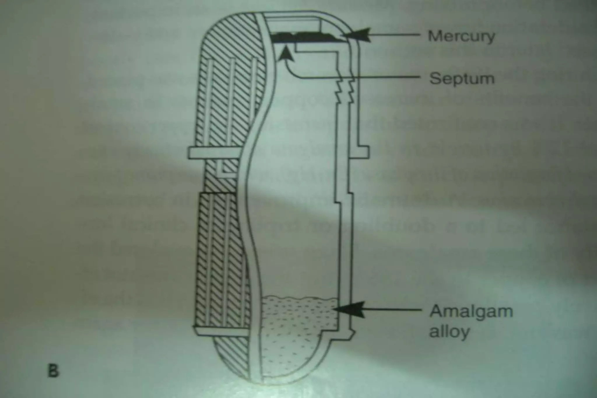
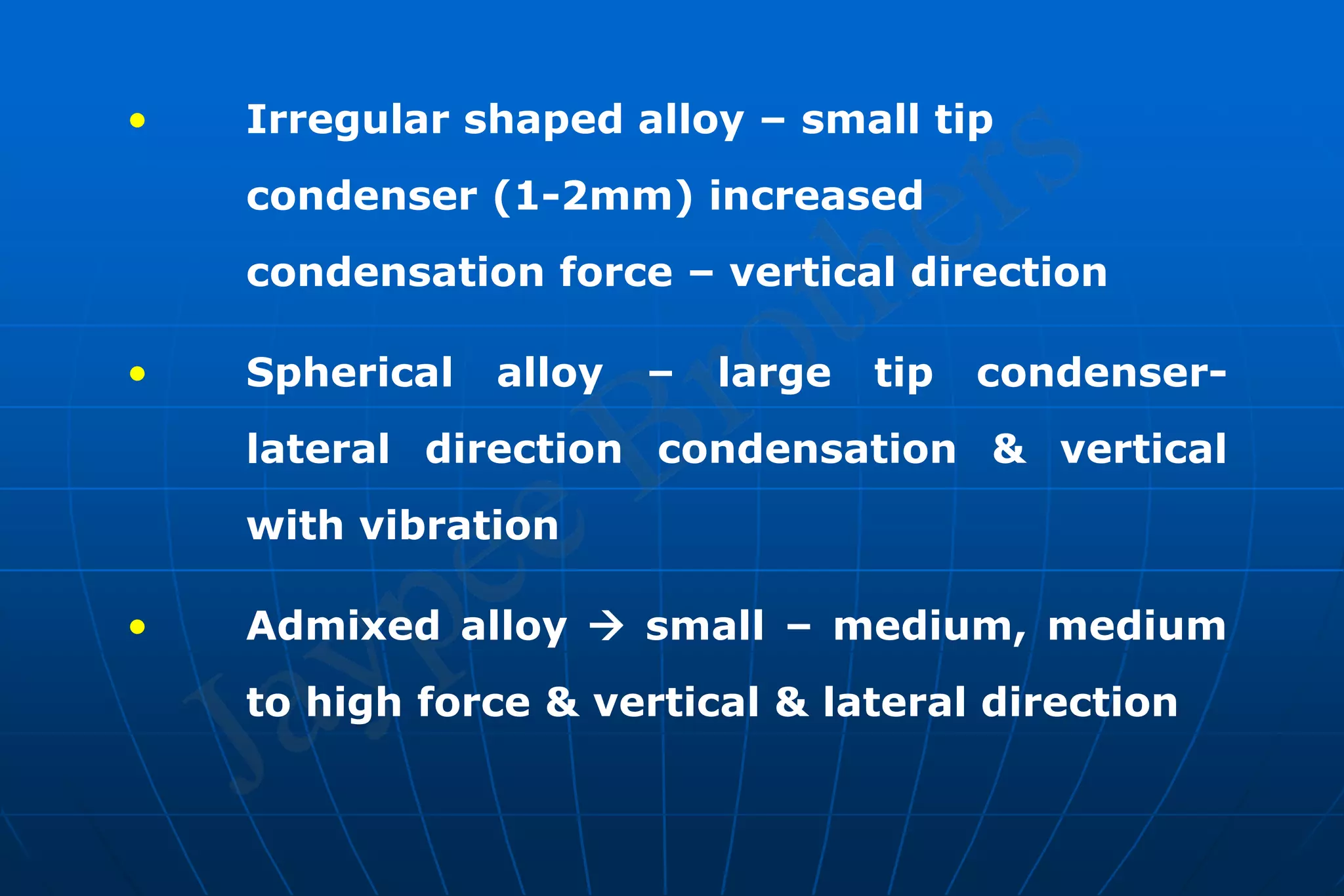
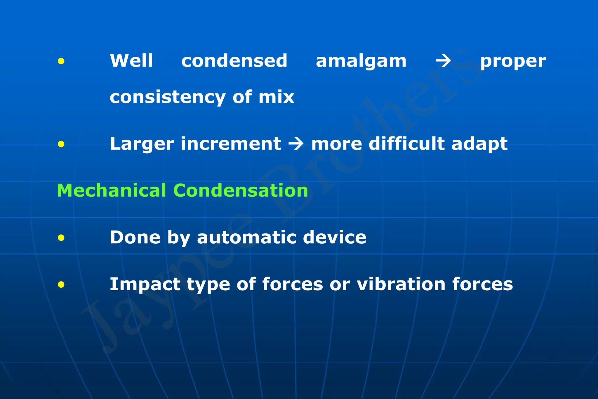
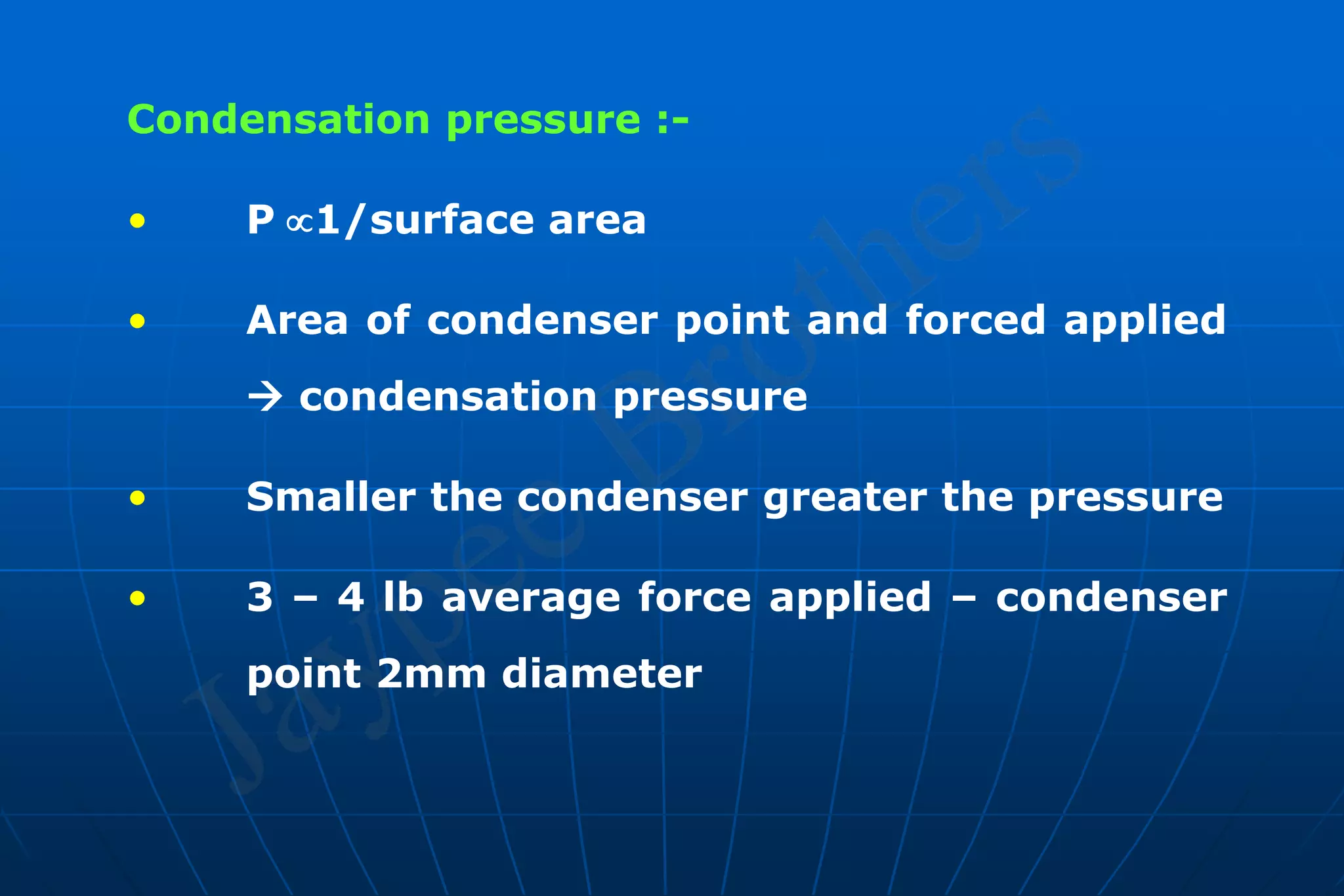
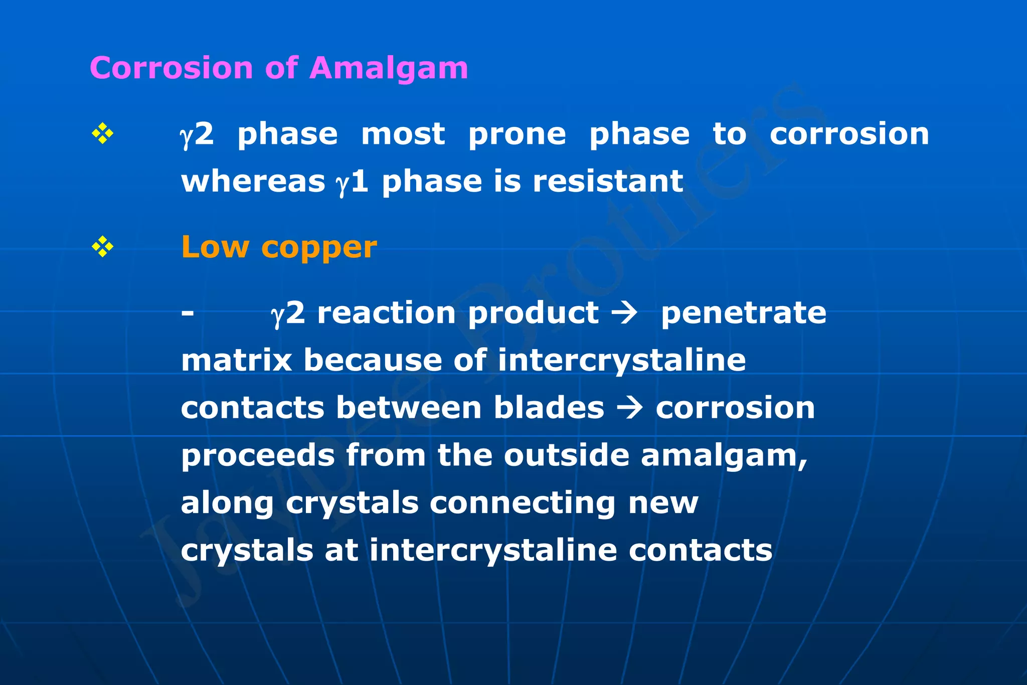
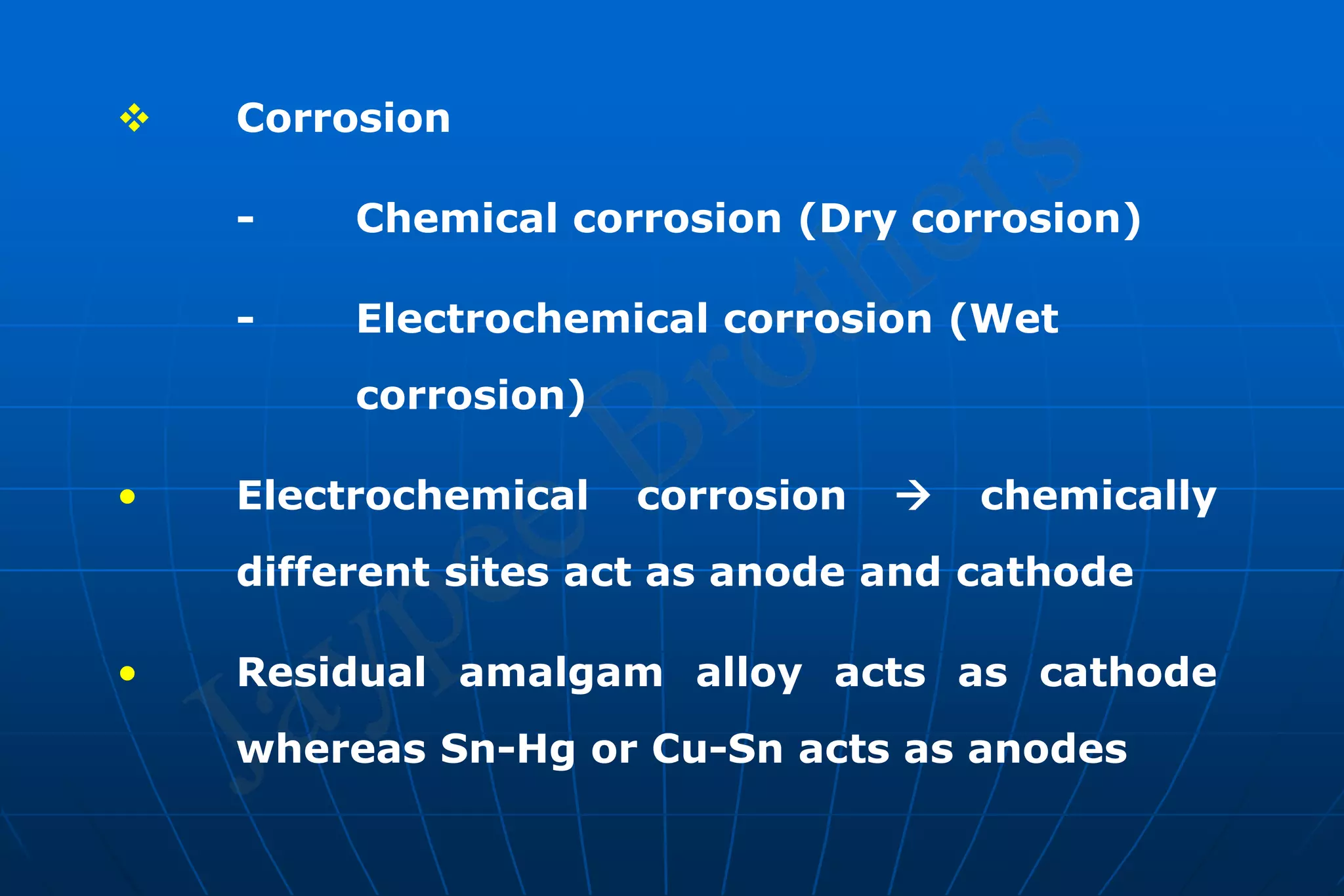
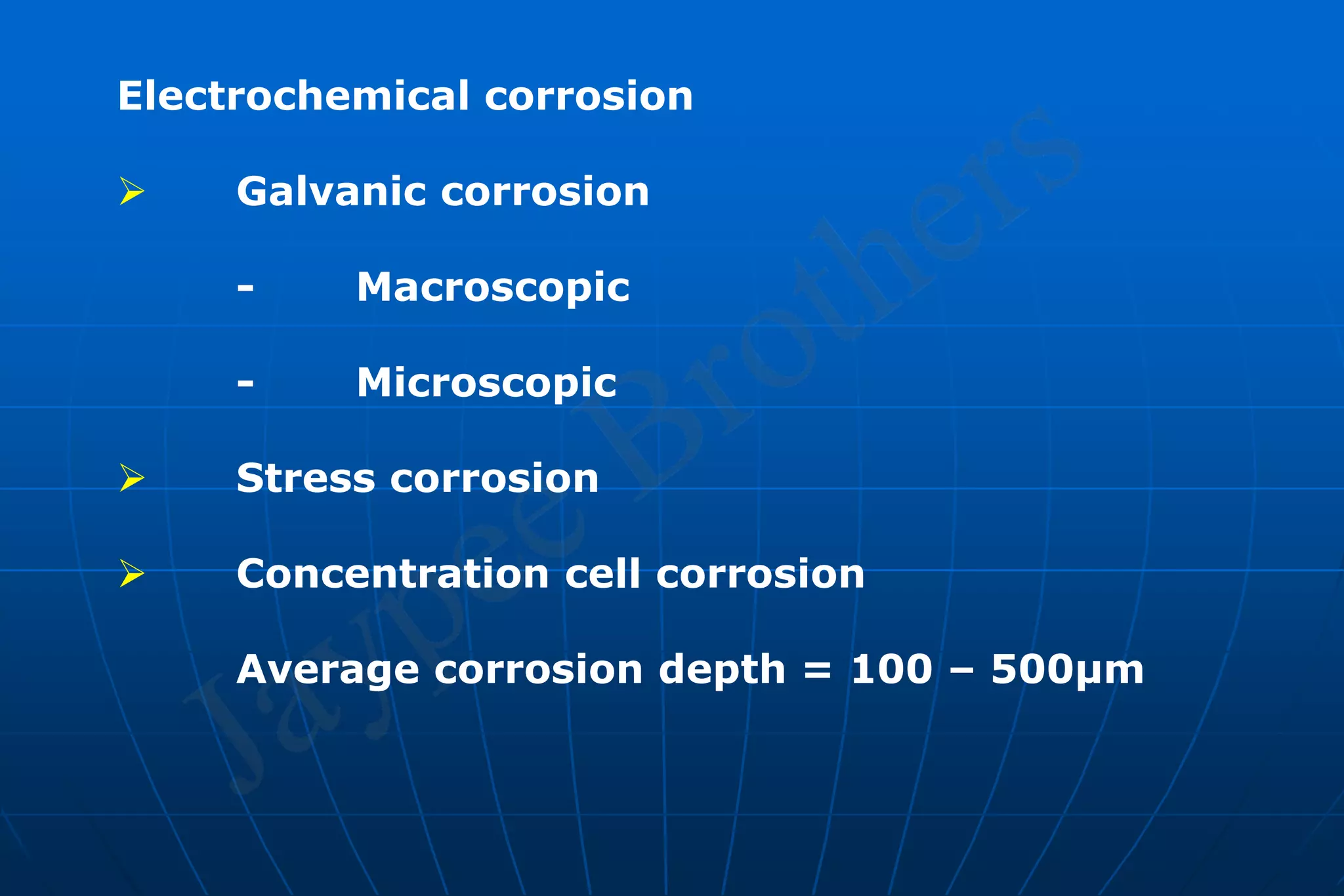
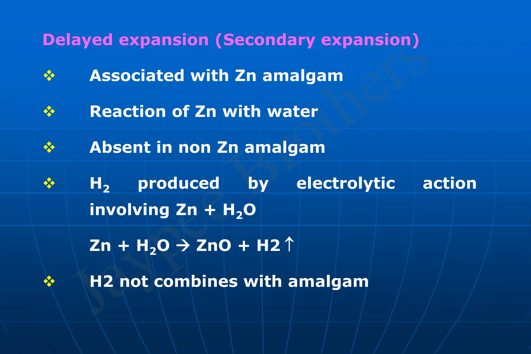
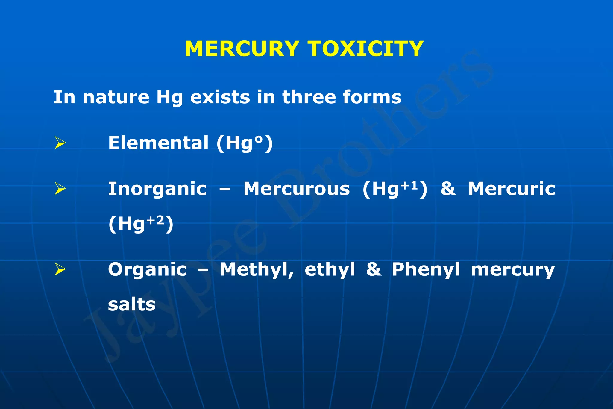
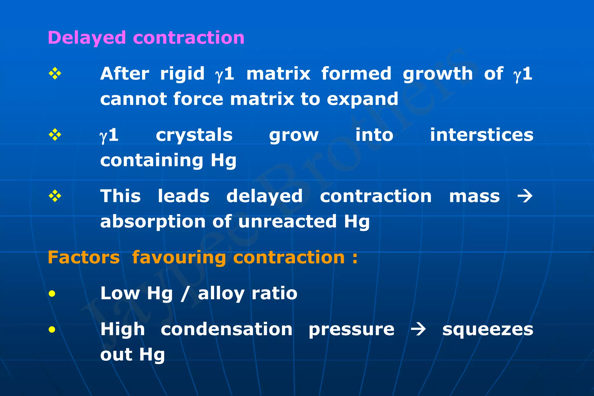
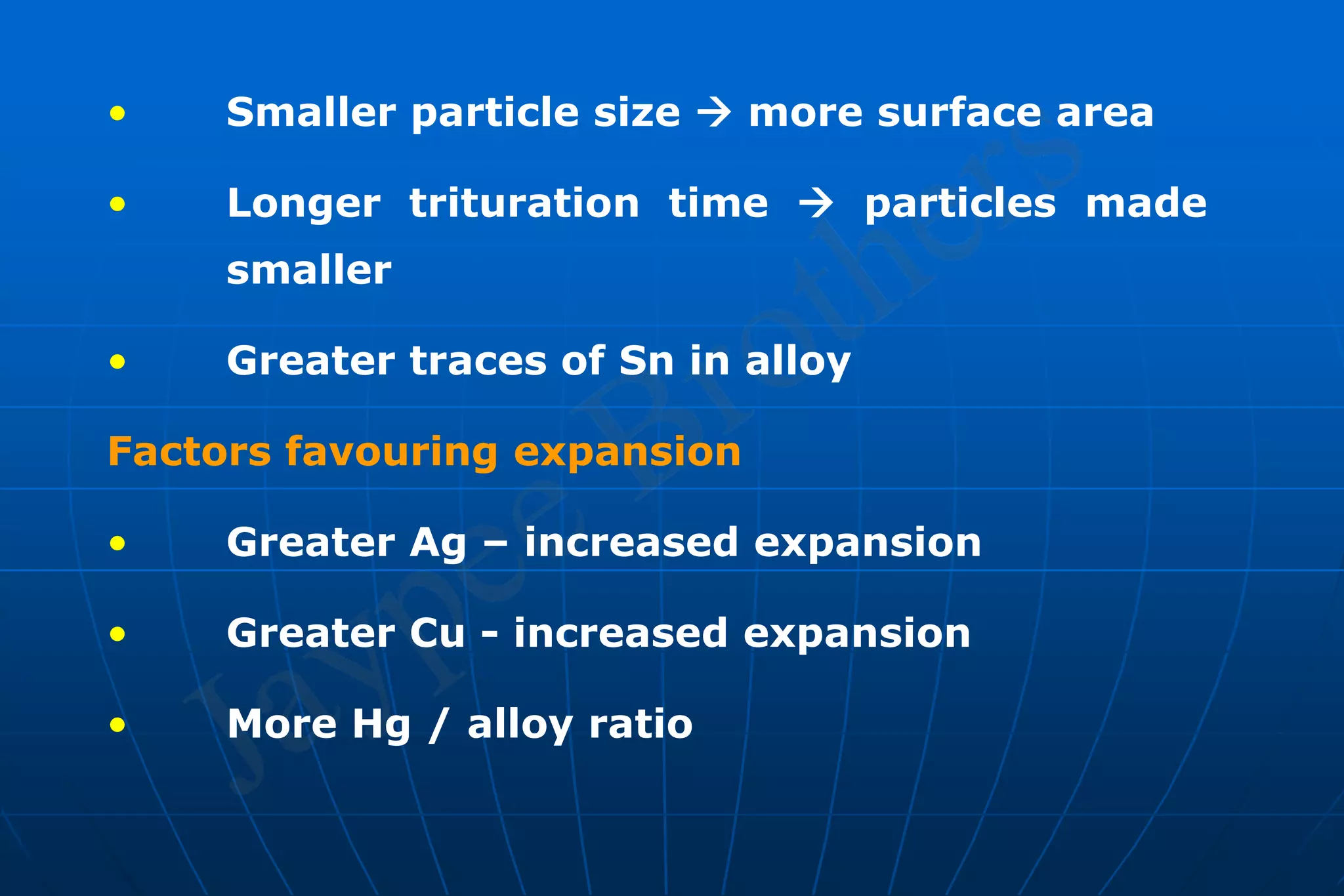
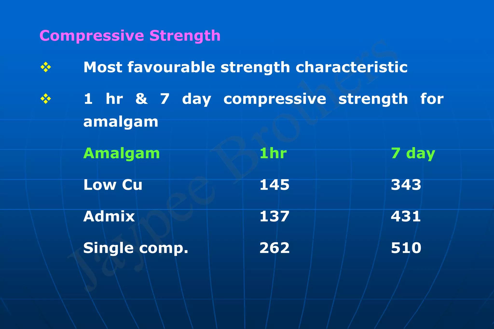
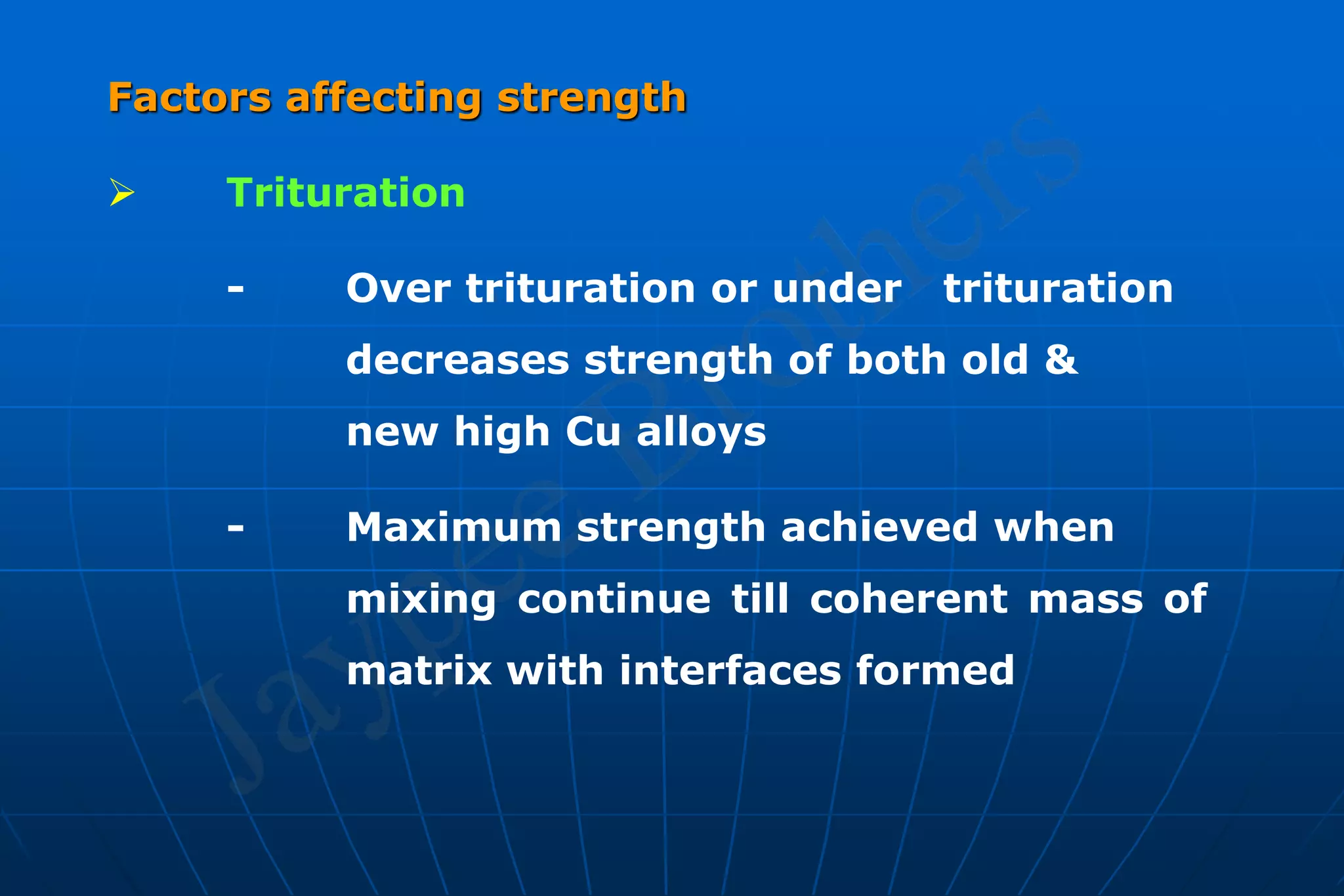
DENTAL AMALGAM
CONTENTS
1. INTRODUCTION
2. HISTORY
3. CLASSIFICATION & COMPOSITION
4 . MODE OF SUPPLY
5 . METALLURGIC PHASES
6. MANUFACTURE
7. SETTING REACTIONS
8. PROPERTIES
9. MANIPULATION
10. FAILURE OF RESTORATIONS
11. MERCURY TOXICITY
12. DEVELOPMENTS IN AMALGAM
13. BONDED AMALGAM RESTORATIONS .
14. CONCLUSION
INTRODUCTION
“Amalgam” derived from Greek word
“Emolient” which means paste.
Amalgam is an alloy of 2 or more metals in
which one of the constituents is essentially Hg.
Dental amalgam is an alloy of Hg, Ag, Cu &
Sn which may contain Zn, Pd & other elements
to improve handling characteristics & clinical
performance. (Kenneth. J. Anusavice)
HISTORY
1800 : (France) – D’ Arcets mineral cement
– 1st dental amalgam alloy of Bi, Pb, Sn & Hg
plasticized at 100°C
1818 : Regnert – Increased amount of Hg &
lower plasticizing temp to 68°C.
1819 : Bell (Eng) – First use of - room
temperature mixed amalgam “Bell’s Putty”.
1826 : O. Taveau (Paris) – used combination of
Ag & Hg to form silver paste.
1833 : Crawcour Bros. (USA) – Royal Mineral
succedanem.
1843 : Resolution passed by American Society of
Dental Surgeons declaring the use of amalgam
as malpractice – FIRST AMALGAM WAR.
1855 : 1st amalgam war ended by breakup of
society
In late 1800’s improved amalgams of
Elisha Townsend, J.F. Flag & G.V. Black – widely
used.
1855 : Elisha Townsend – Ag-Sn-Hg alloy.
1895 : G.V. Black – systematic study on
properties & manipulation of amalgam & its
relation to cavity preparation.
1926 : 2nd AMALGAM WAR – Dr. A. Stock became
poisoned with Hg through 25 years of exposure.
1930 : ADA specification No.1 for amalgam
revised in 1934, 1960 & 1970.
CLASSIFICATION
I. Based on No. of alloyed materials
 Binary : Ag – Sn
 Ternary : Ag – Sn – Cu
 Quarternary : Ag-Sn-Cu-In
II. Based on Cu content
 High Cu (6-30%)
 Low Cu (Less than 6%)
III. Based on Zn content
 Zn free (less than 0.01%)
 Zn containing (0.01% or more)
IV. Based on Powder Particle size
 Microcut
 Fine cut
 Coarse cut
v. Based on composition .
 Unicomposition (Same chemical composition )
 Admixed (spherical eutectic high Cu + lathe cut
low Cu) .
VI. Based on shape of powdered particles .
 Spherical.
 Lathe cut .
 Spheroidal.
VII. Based on addition of noble metals
 Palladium
 Gold
 Platinum
 Indium
VIII. Based on generation
1st Generation – 3 parts Ag +1 part Sn (Peritectic)
2nd Generation–3 parts Ag+1 part Sn+Cu + 1% Zn
3rd Generation – blending spherical Ag-Cu
(Eutectic) to original powder
4th Generation – Alloy Cu to Ag & Sn upto 29%
ternary alloy
5th Generation - Ag + Cu + Sn + In
6th Generation – Alloy Pd (10%), Ag (62%) &
Cu(25%) to 1st, 2nd, 3rd generation
COMPOSITION
1. Low Cu alloy : Ag - 65%
Sn - 29%
Cu - 2 – 5% (< 6%)
Zn - 0 – 2%
2. High Cu alloy :
Admixed
Ag - 65 – 70%
Sn - 17%
Cu - 9 – 20%
Zn - 1 – 2%
Single composition
Ag - 60%
Sn - 27%
Cu - 13 – 30%
Zn - 0 - 2%
Functions of Individual Alloying Metals
1. SILVER
• Whitens alloy
• Decreases Creep
• Increases strength
• Increases setting expansion
• Increase tarnish corrosion
• Decrease setting time
2. TIN
• Decreases setting expansion
• Decreases Strength
• Decrease tarnish resistance
• Increases setting time
3. COPPER
• Decreases brittleness
• Increases hardness
• Increases setting expansion
4. ZINC
• Scavenger
• Increases plasticity
• Decreases tarnish & corrosion
• Prevents oxidation of alloy during
manufacture .
5. PALLADIUM
Increases hardness
• Whitens alloy
6. MERCURY
• Sometimes present in alloy powder in
range of 2 – 3% - PRE AMALGAMATED
ALLOY
MODE OF SUPPLY
 Bulk powder
 Alloy & Hg in disposable capsules
 Pre-weighed alloy as tablets
 Pre-proportioned capsules
METALLURGIC PHASES OF AMALGAM
Silver Tin Alloy
• Silver (73%), Tin (27%) cooled below
480°C  inter metallic compound Ag3Sn is
formed
• Concentration
of Sn < 26%
ß1 phase  solid
solution of Ag &
Sn forms.
• Point C  intermetallic compound Ag3Sn 
forms by peritectic reaction
Influence of Ag-Sn phase on amalgam
• In the range of compositions around 
phase increase or decrease in Ag
influences amount of ß or  phase &
properties of alloy
• If silver content > 73%  setting time
shortened
• If Sn content >27%  mixture of  phase &
Sn rich phase formed
• Sn7 Hg phase lacks corrosion resistance,
weakest phase
• Sn rich alloy  less expansion than Ag rich
• Alloys without Zn  more brittle & less
plastic
• Indium & palladium, < 1%  enhances
physical, mechanical & corrosion resistance
MANUFACTURE
Lathe Cut Powder
Annealed ingot of
alloy  Milling
machine / lathe  cutting
tool / bit.
Chips  needle like
 ball milling
After heating  ingot brought to room temp.
Ingot withdrawn rapidly & quickly quenched 
phase distribution unchanged.
Ingot cooled slowly  proportion of phase
continue to adjust towards room temp equilibrium
ratio.
Ag. Sn : Rapid – Quenching – Maxm amount of ß
phase retained.
Slow cooling  maxm. Amount of 
phase retained.
Homogenizing Anneal
Rapid cooling ingot  cored structure
contains non homogenous grains.
Homogenizing Heat treatment  Re-
establishes equilibrium phase relationship.
Ingot–Oven– heated at a temp below solidus.
Time of heat treatment varies but 24 hr at selected
temperature is not unusual.
Particle Treatment
 Related to preferential dissolution of specific
components from alloy.
 Acid washed powder  More reactive
 Stress induced during ball milling relieved
otherwise  causes changes in alloy
characteristics
 Stress relief  Annealing cycle  100°C
several hrs  Stable in reactivity  increased
shelf life
Atomized Powder
 Melting together desired
elements
 Liquid metal atomized into
fine spherical droplets ; If
droplets solidify before hitting
the surface  Spherical
 Given heat treatment
 Washed with acid
Particle size
 Controlled by manufacturer
 Average particle size = 15 – 35 µm
 Small particle size : increase surface area/vol
increase amount of Hg
 Small average particle size  more rapid
hardening of amalgam  great early strength
 Particle size distribution affects character of
finished surface
SETTING REACTIONS
LOW COPPER
 On trituration Sn & Ag dissolve into Hg .
 Hg has limited solubility for Ag 0.035 wt% & 0.06
wt% for Sn .
 When solubility exceeds, crystals of 2 binary metallic
compds. ppt. into Hg .
 These are body centered cubic Ag2Hg3 (1) & hexagonal
Sn7Hg ( 2) .
 Solubility of Ag< Sn Therefore, 1 ppt.
 After trituration - alloy powder coexists with
liquid Hg - plastic consistency of mix .
 Remaining Hg dissolves alloy particles (Ag-Sn)
covered with newly formed 1 crystals - Rxn.
rate decreases  alloy hardens .
 Hg insufficient to completely consume alloy 
unconsumed particles present in set amalgam .
 Low Cu amalgam  unconsumed particles
embedded in 1 & 2 phases .
 Alloy particles ( β +  )+ Hg - 1 + 2 +
unconsumed alloy.
 Dominating phase in well condensed low copper amalgam is  1 (54
% - 56%) ; unreacted alloy (27%-35%) &  2 (11% - 13%) .
 More the unconsumed alloy , more strong the amalgam .
 Weakest phase   2  least stable in corrosive environment
 Interface between  & 1 matrix important .
  phase strengthens amalgam when bound to matrix .
  > 1 >  2 .
HIGH COPPER -- ADMIXED
 Mixture of lathe cut low Cu alloy & spherical .
 Amalgam made from this alloy stronger .
 Ag – Cu particles + Ag – Sn particles  strong fillers  increase
residual alloy + decrease matrix  strengthening amalgam matrix
increase resistance to marginal breakdown
 30 wt. % - 55 wt. %  spherical high Cu alloy
 Ag Cu alloy  2 phases
- Ag rich
- Cu rich
• Admixed alloy + Hg :
- Ag dissolves in Hg
from Ag – Cu alloy
- Ag + Sn dissolves in
Hg from Ag - Sn alloy
• Sn in solution diffuses to surface of Ag-Cu
particles
• Sn + Cu  Cu6 Sn5 ( phase)
• Layer of  crystals forms around
unconsumed Ag-Cu alloy particles
• 1 forms simultaneously with  phase
• Alloy particles (ß+) + Ag-Cu Eutectic + Hg
 1 +  + unconsumed alloy of both types
of particles
• 2 eliminated & replaced by  therefore Sn
not available for reaction
• To accomplish this net Cu concentration at
least 12% in alloy powder.
Single Composition
Phases found are :
• Ag – Sn (ß)
• Ag3 Sn ()
• Cu3 Sn ()
• Cu6 Sn5 ()
• On trituration :- Ag & Sn phase dissolves in
Hg
• Little Cu dissolves in Hg
• 1 crystals grow  binds together partially
dissolve alloy partilces
•  crystals – meshes of rod like crystals at
surface of alloy particles and in matrix
• Difference of solubility of Ag, Sn & Cu in Hg
plays an important role
• Solubility of Hg in Sn 170 times more than
Cu & 17 times more than Ag
• i.e. Sn more soluble than Ag, Ag more
soluble than Cu & Cu least soluble in Hg
DIFFERENCE BETWEEN LOW Cu & HIGH Cu
Have irregular shapes Have spherical smooth
surface
Made by milling Produced by atomization
Requires more mercury for
mixing & have poor
properties
Requires less mercury &
have better properties
Mix is less plastic & heavy
condensation pressures
Mix is more plastic and is
not sensitive to
condensation pressure
PROPERTIES
1. Dimensional Change
Theory of Dimensional Change
During setting amalgam undergoes 3
distinct successive dimensional changes
 Stage I : Initial contraction
 Stage II : Expansion
 Stage III : Contraction
Initial Contraction
 Alloy – Hg mixed  contraction results
 Hg absorbed  inter particular spaces of
alloy
 Reaction continues – alloy dissolves in Hg
become smaller ; 1 phase grows
 Contraction continues as growth of 1
continues ; this continues in the first
20min
 As 1 grows they impinge against one
another
 Impingement of 1 tends to oppose
contraction
Expansion
 Sufficient Hg present provides plastic mix
 Expansion occurs when 1 crystals impinge
upon one another
 Rigid 1 matrix formed - growth of 1
cannot force matrix to expand
 1 crystals grow into interstices containing
Hg ; consuming Hg & providing continued
reaction
 Low Hg/alloy ratio & high condensation
pressure favours contraction
 Procedures that accelerate setting &
consumption of Hg favours contraction
 Measurement of dimensional change of
modern amalgam reveal net contraction
Mercuroscopic Expansion
 Interface between matrix and  phase
important
 Unconsumed  phase not strengthen
amalgam unless bound to matrix
 Expansion of amalgam at margins
promoted by Hg released from 2 phase
 This Hg re-react with  phase 
mercuroscopic expansion
Delayed contraction
 After rigid 1 matrix formed growth of 1
cannot force matrix to expand
 1 crystals grow into interstices
containing Hg
 This leads delayed contraction mass 
absorption of unreacted Hg
Factors favouring contraction :
• Low Hg / alloy ratio
• High condensation pressure  squeezes
out Hg
• Smaller particle size  more surface area
• Longer trituration time  particles made
smaller
• Greater traces of Sn in alloy
Factors favouring expansion
• Greater Ag – increased expansion
• Greater Cu - increased expansion
• More Hg / alloy ratio
STRENGTH
 ANSI / ADA specification No.1 for amalgam
alloy minimum allowable compressive
strength 1hr after setting when a
cylindrical specimen is compressed at a
rate of 0.25mm/min is 80MPa
 Lack of strength to resist masticatory
forces  inherent weakness
 Most common fracture of amalgam 
margins (Marginal Breakdown) Hastens
corrosion & lead to 2° caries
Measurement of Strength
 Under compressive stress using specimens
of dimension comparable to the volume of
typical amalgam restoration
 Satisfactory amalgam strength  310MPa
 When manipulated properly 7 day
compressive strength  more than 310MPa
 Tensile stresses easily produced
 Amalgam cannot withstand high tensile /
bending stresses
Compressive Strength
 Most favourable strength characteristic
 1 hr & 7 day compressive strength for
amalgam
Amalgam 1hr 7 day
Low Cu 145 343
Admix 137 431
Single comp. 262 510
Factors affecting strength
 Trituration
- Over trituration or under trituration
decreases strength of both old &
new high Cu alloys
- Maximum strength achieved when
mixing continue till coherent mass of
matrix with interfaces formed
- Further trituration  cracks in
crystals & interfaces  drop in
strength of set amalgam
 Effect of Hg content
- Sufficient Hg mixed in alloy  each
alloy particle wetted thoroughly
otherwise dry granular mix  rough
pitted surface
- If sufficient Hg not present 
insufficient matrix formation 
decreased strength
- Hg/ alloy ratio 48-52 %
 Effect of Condensation
- Lathe cut  increased condensation
required to squeeze out Hg
- Increase condensation pressure 
decrease porosity & increased
strength
- Spherical alloy  light condensation
pressure to reach adequate strength
 Porosities
- Cannot be avoided in an
agglomerated mass
- Result in area of stress concentration
; propagation cracks ; corrosion &
fracture of restoration
CREEP
Significance on amalgam performance
 Creep rate correlate with marginal
breakdown of low Cu amalgams
 Creep rate of high Cu amalgams 0.4%
 Creep rate below 3% specified in
ANSI/ADA specification No.1
 Creep rate of low Cu amalgam range
between 0.8 – 8%
Influence of microstructure on creep
 1 exert primary influence on low Cu
amalgam creep rates
 Creep increases with 1 vol. fractions &
decreases with larger 1 grain size.
 2  higher creep rates
Effect of Manipulative variables on Creep
 Hg / alloy ratio minimized
 Condensation pressure maximized for lathe
cut or admixed
 Timing of trituration
MANIPULATION
Hg / Alloy Ratio
 To achieve smooth plastic amalgam mixes 
Hg used in excess
 Excess Hg has deleterious effects
 To reduce amount of Hg
- Excess Hg squeezed out
- Increasing dryness technique :
Hg expressed in increasing amounts
from each successive increment with each new
increment serving as a Blotter.
- Reduce original Hg / alloy ratio (Eames
Tech/Minimal Hg Tech) [1:1]
• Sufficient Hg provides coherent
plastic mass
• Hg content of finished restoration
comparable to original Hg alloy
ratio
• Usually 50% with lesser amounts
with spherical alloys
• Technique reduces contact and
contamination with metallic Hg
Proportioning
 Amount of alloy & Hg to use  Hg/alloy ratio
 Signifies parts by weight of Hg & Alloy
 Mix of amalgam with Hg/alloy ratio 6:5
contains 54.5% Hg
 Recommended ratio for lathe cut alloys  1:1
(50% Hg)
 Recommended amount of Hg for spherical
alloys  42%
 If Hg content low mix dry & grainy with
insufficient matrix
 Wide variety of Hg & alloy dispensers
available
• Dispensers based on volumetric
proportioning
• Pre-weighed pellets or tablets
• Disposable capsule
 Hg is measured by volume
 Dispenser held vertically
TRITURATION
Objective of Trituration :
 Attain workable plastic mass
 Rub of oxide films from alloy particles
 To pulverize pellets into particles
 To dissolve alloy in Hg for formation of
matrix crystals
 To keep matrix crystals as small as possible
 Mixing of alloy with Hg  Trituration
traditionally Mortar & Pestle were used.
 Mechanical device amalgamator saves
time & standardizes procedure
 Amalgamator:3 speeds :- Low- 3200 to 3400
Medium-3700 to 3800
High – 4000 to 4400
Principle of Operation
• Capsule serves as a mortar
• Cylindrical metal / plastic piston – pestle
• Alloy & Hg dispensed into capsule
• Capsule secured in machine & turned on
• Arms holding capsule oscillate – trituration
accomplished
• Automatic timer for control of mixing time
 Capsule
- Friction fit
- Screw cap led
 Wide variety capsule pestle combination
available
- One piece construction : No Hg released
 Diameter & length of pestle < dimensions of
capsule
MULLING
 Continuation of trituration causes mix to
cohere
 Mix enveloped in a dry piece of rubber dam
vigorously rubbed of one hand and palm of
another hand for 2 – 5 seconds
 After mechanical trituration mix removed &
triturated in pestle free capsule for 2-3 sec.
CONSISTENCY
 Attainment of a proper mix controlled by
timing trituration
 Grainy Mix  under triturated
Mixing Variables
 Under mixing
• Appears dull
• Crumbly and grainy in consistency
• Rough surface after carving
• Mercury in excess/ hardens rapidly
• Strength is less
• Prone to tarnish and corrosion
 Over Triturated
• Wet & plastic
• Difficult to remove from capsule
• Working time decreased
• Sets rapidly
• Increased contraction & increased creep
• Decrease strength
 Normal Mix
• Wet & plastic
• Smooth, soft consistency with shiny
surface
• Good strength
• Mix is warm when removed from the
capsule
• Carved surface retain lusture
CONDENSATION
• Compacts alloy so that greatest possible
density attained
• Hg rich amalgam brought on top of each
increment
• Delayed condensation  weaker amalgam
• Good isolation in zinc containing alloy
• Ultrasonic condensers not recommended
• Increases strength, decreases creep
(7-10MPa)
• Irregular shaped alloy – small tip
condenser (1-2mm) increased
condensation force – vertical direction
• Spherical alloy – large tip condenser-
lateral direction condensation & vertical
with vibration
• Admixed alloy  small – medium, medium
to high force & vertical & lateral direction
Hand Condensation
• Never touch with bare hands
• Increments carried & inserted by amalgam
carrier.
• Condenser point forced into amalgam 
avoids voids, adapt to wall
• Shiny surface after condensation of each
increment
• Continued till cavity overfilled
• Well condensed amalgam  proper
consistency of mix
• Larger increment  more difficult adapt
Mechanical Condensation
• Done by automatic device
• Impact type of forces or vibration forces
Condensation pressure :-
• P1/surface area
• Area of condenser point and forced applied
 condensation pressure
• Smaller the condenser greater the pressure
• 3 – 4 lb average force applied – condenser
point 2mm diameter
BURNISHING
• Process of marginal adaptation of amalgam
• Ball burnisher used in light strokes from
amalgam towards tooth surface
• Undue pressure & heat generation avoided
during burnishing
CARVING, FINISHING & POLISHING
• Objective carving  simulate tooth
anatomy
• Prevents over hanging restorations at
proximal surface
• If carving too deep at marginal areas 
fracture
• Amalgam ready for carving soon after
condensation
• Carving proceeds in direction parallel or
slightly towards the margin of tooth
• Burnishing alone not provide scratch free &
retention free surface
• Slow speed handpieces  finishing &
polishing amalgam
• Restoration surface finished initially with
fine prophylactic paste applied with cotton
pellet / non ribbed rubber cup  light
pressure
• If amalgam hardened
- Contour with slow speed green
stones or diamond bur, brown &
green rubber points
- Mixture of fine pumice & water /
alcohol with a rotary brush or
felt wheel
FAILURE OF RESTORATIONS
Tarnish & Corrosion
 Tarnish  process in which a metal surface
loses its lusture and gets discolored
 Surface discoloration  formation of
oxides, sulphides or chloride on the
surface. Zn can produce ZnO layer on the
occlusal surface
 Corrosion  chemical or electrochemical
process by which metal undergoes actual
deterioration by reaction with environment
Corrosion of Amalgam
 2 phase most prone phase to corrosion
whereas 1 phase is resistant
 Low copper
- 2 reaction product  penetrate
matrix because of intercrystaline
contacts between blades  corrosion
proceeds from the outside amalgam,
along crystals connecting new
crystals at intercrystaline contacts
- Penetrating corrosion  generates a
porous, spongy amalgam with
minimum restoration
 High copper
- Sn-Hg particles replaced by Cu-Sn
phase.
- Cu-Sn phase corrosion prone, but less
when compared to Sn-Hg
- In Cu-Sn penetrating corrosion does
not takes place
 Corrosion
- Chemical corrosion (Dry corrosion)
- Electrochemical corrosion (Wet
corrosion)
• Electrochemical corrosion  chemically
different sites act as anode and cathode
• Residual amalgam alloy acts as cathode
whereas Sn-Hg or Cu-Sn acts as anodes
Electrochemical corrosion
 Galvanic corrosion
- Macroscopic
- Microscopic
 Stress corrosion
 Concentration cell corrosion
Average corrosion depth = 100 – 500µm
Delayed expansion (Secondary expansion)
 Associated with Zn amalgam
 Reaction of Zn with water
 Absent in non Zn amalgam
 H2 produced by electrolytic action
involving Zn + H2O
Zn + H2O  ZnO + H2
 H2 not combines with amalgam
• Collects within restoration; increases
internal pressure  amalgam to creep 
expansion
• Starts 3 – 5 days after placing restoration
• Reaching values greater than 400µ (4%)
• Contamination occurs any time during
manipulation & insertion
• Severe expansion cause pressure on pulp
 severe pain
• Pressure centered can go upto 2000 lb/sq
inch
Marginal Ditching
 Secondary expansion  throughout clinical
life of an amalgam
 On non-occlusal surface entire restoration
may appear extruded.
 On extruded surface the abrasion and
attrition tend to limit the overall extrusion.
 Occlusal margins become fracture
susceptible ledges elevated from natural
contours of enamel
 Extrusion at margins is promoted by
electrochemical corrosion (Mercuroscopic
expansion)
 Most common evidence of degradation of
amalgam is marginal fracture.
 Combination of brittleness, low tensile
strength and electrochemical corrosion 
marginal fracture
 At some point occlusal stresses of opposing
tooth contact creates local fractures 
produces a ditch  marginal ditching.
 Measured on basis of ‘Mahler’s Scale’
Amalgam Blues
 Discolored area seen through enamel in
teeth having amalgam restoration
 Bluish hue results from
- Leaching of corrosion products of
amalgam into the dentinal tubules
- From colour of underlying amalgam
seen through translucent enamel
Amalgam Tattoo
 Macular bluish gray or black lesions on the
buccal mucosa, gingiva or palate, present
in vicinity of teeth with large amalgam
restorations.
 Due to
- Iatrogenic mishap
- Fragments gets deposited from
multiple tooth extractions containing
amalgams
MERCURY TOXICITY
In nature Hg exists in three forms
 Elemental (Hg°)
 Inorganic – Mercurous (Hg+1) & Mercuric
(Hg+2)
 Organic – Methyl, ethyl & Phenyl mercury
salts
Hg released from dental restorations
 Hg vapour can be kept low
- Care in preparation of amalgam
- Avoiding ultrasonic condensor
- Adequate water spray & high volume
suction during cutting or polishing
- Use of rubber dam
 Magnitude & proportion of the released
mercury level  surface area of the
restoration
 Hg release by high Cu < low Cu
Safe & Threshold levels of Mercury
 Maximum level of occupational exposure
considered safe is 50mg Hg/m3 of air
 Maximum allowed concentration in blood –
5ng/ml of blood
 Maximum allowed concentration in urine –
15mg/1 to 20mg / 1 of urine
 Threshold value for workers in mercury
industry – 350 to 500mg Hg/m3 of air
ENVIRONMENTAL HAZARDS OF MERCURY
Minamata Disease
 Tragedy of Minamata Bay in the 1950’s .
 Symptoms of Hg poisoning during this
incident were : (1) ataxic gait (2)
convulsions (3) numbness in mouth &
limbs (4) difficulty in speaking
DEVELOPMENTS IN AMALGAM
Gallium Alloys
 Gallium was one of the substitutes
suggested for mercury by Puttkammer
(1928)
 This direct filling material contains no
mercury.
 Based on ability of liquid gallium to wet
surfaces of many solids like Hg, gallium is
liquid at room temperature
Disadvantages
1. Low resistance to corrosion
2. Gallium alloy & high Cu amalgam placed
in oral cavity, galvanic corrosion with
preferential corrosion of gallium alloy.
3. Difficult handling  wetting & adhesive
property
4. Gallium alloy dark residue on gloves
5. High cost
Hg free direct filling silver alloys
 Daniel et al (1994)
 Ag particles suspended in dil. Acid solution
 Physical properties showed higher rupture
strength than amalgam .
 Consolidated silver – cold welded system –
rotary instrument for contouring & finishing
Indium containing alloy & binary mercury –
Indium liquid alloy
 Powell et al in 1989
 Pure indium powder admixed into dispersed
phase high Cu alloy .
 Decrease in mercury evaporation
 As the amount of indium increased from 0 to
14%  decrease in Hg vapour .
 Commercially available in name of
‘Indisperse’
Fluoride containing amalgam
 Innes & Youdelis 1966, Jerman in 1970 &
Stoner et al 1971
- Dilution of salt crystals that are in
contact with cavity wall
- By corrosion that liberates fluorides
contained in the mass of amalgam.
e.g. Fluoralloy – Dentoria SA, France
Low Mercury Amalgam
 In these amalgams, mercury is used as
low as at 15 to 25% .
BONDED AMALGAM RESTORATIONS
 Introduced by Baldwin in 1897
 Condensation of amalgam on to and into
the unset zinc phosphate cement
 Adhesive cements such as zinc
polycarboxylate & GIC, suggested
substitutes for zinc phosphate cement
Advantages
 Conservative preparation .
 Increased fracture resistance of the tooth
 Reduced micro leakage,lower incidence of
recurrent caries, post operative pain &
pulpal damage
 Conservative repair of existing restorations
 In 1986 Varga et al employed 4-META &
Panavia Ex Resin as the intermediate bonding
agents.
 Masaka (1989)  Panvia Ex be abandoned in
in favour of 4 – META .
 “AMALGAMBOND” was developed .
CONCLUSION
Amalgam has provided valuable and comparatively
inexpensive service to patients longer than any
other material available .
It has many positive attributes and
remains an important part of dentist’s restorative
resource .
Mercury free alloys are likely to be
available to provide the advantages of amalgam
without environmental concerns about mercury .
Dental Amalgam.ppt

Dental Amalgam.ppt

  • 1.
  • 2.
    CONTENTS 1. INTRODUCTION 2. HISTORY 3.CLASSIFICATION & COMPOSITION 4 . MODE OF SUPPLY 5 . METALLURGIC PHASES 6. MANUFACTURE 7. SETTING REACTIONS 8. PROPERTIES 9. MANIPULATION 10. FAILURE OF RESTORATIONS 11. MERCURY TOXICITY 12. DEVELOPMENTS IN AMALGAM 13. BONDED AMALGAM RESTORATIONS . 14. CONCLUSION
  • 3.
    INTRODUCTION “Amalgam” derived fromGreek word “Emolient” which means paste. Amalgam is an alloy of 2 or more metals in which one of the constituents is essentially Hg. Dental amalgam is an alloy of Hg, Ag, Cu & Sn which may contain Zn, Pd & other elements to improve handling characteristics & clinical performance. (Kenneth. J. Anusavice)
  • 4.
    HISTORY 1800 : (France)– D’ Arcets mineral cement – 1st dental amalgam alloy of Bi, Pb, Sn & Hg plasticized at 100°C 1818 : Regnert – Increased amount of Hg & lower plasticizing temp to 68°C. 1819 : Bell (Eng) – First use of - room temperature mixed amalgam “Bell’s Putty”.
  • 5.
    1826 : O.Taveau (Paris) – used combination of Ag & Hg to form silver paste. 1833 : Crawcour Bros. (USA) – Royal Mineral succedanem. 1843 : Resolution passed by American Society of Dental Surgeons declaring the use of amalgam as malpractice – FIRST AMALGAM WAR.
  • 6.
    1855 : 1stamalgam war ended by breakup of society In late 1800’s improved amalgams of Elisha Townsend, J.F. Flag & G.V. Black – widely used. 1855 : Elisha Townsend – Ag-Sn-Hg alloy.
  • 7.
    1895 : G.V.Black – systematic study on properties & manipulation of amalgam & its relation to cavity preparation. 1926 : 2nd AMALGAM WAR – Dr. A. Stock became poisoned with Hg through 25 years of exposure. 1930 : ADA specification No.1 for amalgam revised in 1934, 1960 & 1970.
  • 8.
    CLASSIFICATION I. Based onNo. of alloyed materials  Binary : Ag – Sn  Ternary : Ag – Sn – Cu  Quarternary : Ag-Sn-Cu-In II. Based on Cu content  High Cu (6-30%)  Low Cu (Less than 6%)
  • 9.
    III. Based onZn content  Zn free (less than 0.01%)  Zn containing (0.01% or more) IV. Based on Powder Particle size  Microcut  Fine cut  Coarse cut
  • 10.
    v. Based oncomposition .  Unicomposition (Same chemical composition )  Admixed (spherical eutectic high Cu + lathe cut low Cu) . VI. Based on shape of powdered particles .  Spherical.  Lathe cut .  Spheroidal.
  • 11.
    VII. Based onaddition of noble metals  Palladium  Gold  Platinum  Indium VIII. Based on generation 1st Generation – 3 parts Ag +1 part Sn (Peritectic) 2nd Generation–3 parts Ag+1 part Sn+Cu + 1% Zn
  • 12.
    3rd Generation –blending spherical Ag-Cu (Eutectic) to original powder 4th Generation – Alloy Cu to Ag & Sn upto 29% ternary alloy 5th Generation - Ag + Cu + Sn + In 6th Generation – Alloy Pd (10%), Ag (62%) & Cu(25%) to 1st, 2nd, 3rd generation
  • 13.
    COMPOSITION 1. Low Cualloy : Ag - 65% Sn - 29% Cu - 2 – 5% (< 6%) Zn - 0 – 2% 2. High Cu alloy : Admixed Ag - 65 – 70% Sn - 17% Cu - 9 – 20% Zn - 1 – 2%
  • 14.
    Single composition Ag -60% Sn - 27% Cu - 13 – 30% Zn - 0 - 2% Functions of Individual Alloying Metals 1. SILVER • Whitens alloy • Decreases Creep • Increases strength • Increases setting expansion • Increase tarnish corrosion • Decrease setting time
  • 15.
    2. TIN • Decreasessetting expansion • Decreases Strength • Decrease tarnish resistance • Increases setting time 3. COPPER • Decreases brittleness • Increases hardness • Increases setting expansion 4. ZINC • Scavenger • Increases plasticity • Decreases tarnish & corrosion • Prevents oxidation of alloy during manufacture .
  • 16.
    5. PALLADIUM Increases hardness •Whitens alloy 6. MERCURY • Sometimes present in alloy powder in range of 2 – 3% - PRE AMALGAMATED ALLOY
  • 17.
    MODE OF SUPPLY Bulk powder  Alloy & Hg in disposable capsules  Pre-weighed alloy as tablets  Pre-proportioned capsules
  • 18.
    METALLURGIC PHASES OFAMALGAM Silver Tin Alloy • Silver (73%), Tin (27%) cooled below 480°C  inter metallic compound Ag3Sn is formed • Concentration of Sn < 26% ß1 phase  solid solution of Ag & Sn forms. • Point C  intermetallic compound Ag3Sn  forms by peritectic reaction
  • 19.
    Influence of Ag-Snphase on amalgam • In the range of compositions around  phase increase or decrease in Ag influences amount of ß or  phase & properties of alloy • If silver content > 73%  setting time shortened • If Sn content >27%  mixture of  phase & Sn rich phase formed • Sn7 Hg phase lacks corrosion resistance, weakest phase
  • 20.
    • Sn richalloy  less expansion than Ag rich • Alloys without Zn  more brittle & less plastic • Indium & palladium, < 1%  enhances physical, mechanical & corrosion resistance
  • 21.
    MANUFACTURE Lathe Cut Powder Annealedingot of alloy  Milling machine / lathe  cutting tool / bit. Chips  needle like  ball milling
  • 22.
    After heating ingot brought to room temp. Ingot withdrawn rapidly & quickly quenched  phase distribution unchanged. Ingot cooled slowly  proportion of phase continue to adjust towards room temp equilibrium ratio. Ag. Sn : Rapid – Quenching – Maxm amount of ß phase retained. Slow cooling  maxm. Amount of  phase retained.
  • 23.
    Homogenizing Anneal Rapid coolingingot  cored structure contains non homogenous grains. Homogenizing Heat treatment  Re- establishes equilibrium phase relationship. Ingot–Oven– heated at a temp below solidus. Time of heat treatment varies but 24 hr at selected temperature is not unusual.
  • 24.
    Particle Treatment  Relatedto preferential dissolution of specific components from alloy.  Acid washed powder  More reactive  Stress induced during ball milling relieved otherwise  causes changes in alloy characteristics  Stress relief  Annealing cycle  100°C several hrs  Stable in reactivity  increased shelf life
  • 25.
    Atomized Powder  Meltingtogether desired elements  Liquid metal atomized into fine spherical droplets ; If droplets solidify before hitting the surface  Spherical  Given heat treatment  Washed with acid
  • 26.
    Particle size  Controlledby manufacturer  Average particle size = 15 – 35 µm  Small particle size : increase surface area/vol increase amount of Hg  Small average particle size  more rapid hardening of amalgam  great early strength  Particle size distribution affects character of finished surface
  • 27.
    SETTING REACTIONS LOW COPPER On trituration Sn & Ag dissolve into Hg .  Hg has limited solubility for Ag 0.035 wt% & 0.06 wt% for Sn .  When solubility exceeds, crystals of 2 binary metallic compds. ppt. into Hg .  These are body centered cubic Ag2Hg3 (1) & hexagonal Sn7Hg ( 2) .  Solubility of Ag< Sn Therefore, 1 ppt.
  • 28.
     After trituration- alloy powder coexists with liquid Hg - plastic consistency of mix .  Remaining Hg dissolves alloy particles (Ag-Sn) covered with newly formed 1 crystals - Rxn. rate decreases  alloy hardens .  Hg insufficient to completely consume alloy  unconsumed particles present in set amalgam .  Low Cu amalgam  unconsumed particles embedded in 1 & 2 phases .  Alloy particles ( β +  )+ Hg - 1 + 2 + unconsumed alloy.
  • 30.
     Dominating phasein well condensed low copper amalgam is  1 (54 % - 56%) ; unreacted alloy (27%-35%) &  2 (11% - 13%) .  More the unconsumed alloy , more strong the amalgam .  Weakest phase   2  least stable in corrosive environment  Interface between  & 1 matrix important .   phase strengthens amalgam when bound to matrix .   > 1 >  2 .
  • 31.
    HIGH COPPER --ADMIXED  Mixture of lathe cut low Cu alloy & spherical .  Amalgam made from this alloy stronger .  Ag – Cu particles + Ag – Sn particles  strong fillers  increase residual alloy + decrease matrix  strengthening amalgam matrix increase resistance to marginal breakdown  30 wt. % - 55 wt. %  spherical high Cu alloy  Ag Cu alloy  2 phases - Ag rich - Cu rich
  • 32.
    • Admixed alloy+ Hg : - Ag dissolves in Hg from Ag – Cu alloy - Ag + Sn dissolves in Hg from Ag - Sn alloy • Sn in solution diffuses to surface of Ag-Cu particles • Sn + Cu  Cu6 Sn5 ( phase) • Layer of  crystals forms around unconsumed Ag-Cu alloy particles
  • 33.
    • 1 formssimultaneously with  phase • Alloy particles (ß+) + Ag-Cu Eutectic + Hg  1 +  + unconsumed alloy of both types of particles • 2 eliminated & replaced by  therefore Sn not available for reaction • To accomplish this net Cu concentration at least 12% in alloy powder.
  • 34.
    Single Composition Phases foundare : • Ag – Sn (ß) • Ag3 Sn () • Cu3 Sn () • Cu6 Sn5 () • On trituration :- Ag & Sn phase dissolves in Hg • Little Cu dissolves in Hg • 1 crystals grow  binds together partially dissolve alloy partilces
  • 35.
    •  crystals– meshes of rod like crystals at surface of alloy particles and in matrix • Difference of solubility of Ag, Sn & Cu in Hg plays an important role • Solubility of Hg in Sn 170 times more than Cu & 17 times more than Ag • i.e. Sn more soluble than Ag, Ag more soluble than Cu & Cu least soluble in Hg
  • 36.
    DIFFERENCE BETWEEN LOWCu & HIGH Cu Have irregular shapes Have spherical smooth surface Made by milling Produced by atomization Requires more mercury for mixing & have poor properties Requires less mercury & have better properties Mix is less plastic & heavy condensation pressures Mix is more plastic and is not sensitive to condensation pressure
  • 37.
    PROPERTIES 1. Dimensional Change Theoryof Dimensional Change During setting amalgam undergoes 3 distinct successive dimensional changes  Stage I : Initial contraction  Stage II : Expansion  Stage III : Contraction
  • 38.
    Initial Contraction  Alloy– Hg mixed  contraction results  Hg absorbed  inter particular spaces of alloy  Reaction continues – alloy dissolves in Hg become smaller ; 1 phase grows  Contraction continues as growth of 1 continues ; this continues in the first 20min  As 1 grows they impinge against one another  Impingement of 1 tends to oppose contraction
  • 39.
    Expansion  Sufficient Hgpresent provides plastic mix  Expansion occurs when 1 crystals impinge upon one another  Rigid 1 matrix formed - growth of 1 cannot force matrix to expand  1 crystals grow into interstices containing Hg ; consuming Hg & providing continued reaction  Low Hg/alloy ratio & high condensation pressure favours contraction  Procedures that accelerate setting & consumption of Hg favours contraction  Measurement of dimensional change of modern amalgam reveal net contraction
  • 40.
    Mercuroscopic Expansion  Interfacebetween matrix and  phase important  Unconsumed  phase not strengthen amalgam unless bound to matrix  Expansion of amalgam at margins promoted by Hg released from 2 phase  This Hg re-react with  phase  mercuroscopic expansion
  • 41.
    Delayed contraction  Afterrigid 1 matrix formed growth of 1 cannot force matrix to expand  1 crystals grow into interstices containing Hg  This leads delayed contraction mass  absorption of unreacted Hg Factors favouring contraction : • Low Hg / alloy ratio • High condensation pressure  squeezes out Hg
  • 42.
    • Smaller particlesize  more surface area • Longer trituration time  particles made smaller • Greater traces of Sn in alloy Factors favouring expansion • Greater Ag – increased expansion • Greater Cu - increased expansion • More Hg / alloy ratio
  • 43.
    STRENGTH  ANSI /ADA specification No.1 for amalgam alloy minimum allowable compressive strength 1hr after setting when a cylindrical specimen is compressed at a rate of 0.25mm/min is 80MPa  Lack of strength to resist masticatory forces  inherent weakness  Most common fracture of amalgam  margins (Marginal Breakdown) Hastens corrosion & lead to 2° caries
  • 44.
    Measurement of Strength Under compressive stress using specimens of dimension comparable to the volume of typical amalgam restoration  Satisfactory amalgam strength  310MPa  When manipulated properly 7 day compressive strength  more than 310MPa  Tensile stresses easily produced  Amalgam cannot withstand high tensile / bending stresses
  • 45.
    Compressive Strength  Mostfavourable strength characteristic  1 hr & 7 day compressive strength for amalgam Amalgam 1hr 7 day Low Cu 145 343 Admix 137 431 Single comp. 262 510
  • 46.
    Factors affecting strength Trituration - Over trituration or under trituration decreases strength of both old & new high Cu alloys - Maximum strength achieved when mixing continue till coherent mass of matrix with interfaces formed
  • 47.
    - Further trituration cracks in crystals & interfaces  drop in strength of set amalgam  Effect of Hg content - Sufficient Hg mixed in alloy  each alloy particle wetted thoroughly otherwise dry granular mix  rough pitted surface - If sufficient Hg not present  insufficient matrix formation  decreased strength - Hg/ alloy ratio 48-52 %
  • 48.
     Effect ofCondensation - Lathe cut  increased condensation required to squeeze out Hg - Increase condensation pressure  decrease porosity & increased strength - Spherical alloy  light condensation pressure to reach adequate strength  Porosities - Cannot be avoided in an agglomerated mass - Result in area of stress concentration ; propagation cracks ; corrosion & fracture of restoration
  • 49.
    CREEP Significance on amalgamperformance  Creep rate correlate with marginal breakdown of low Cu amalgams  Creep rate of high Cu amalgams 0.4%  Creep rate below 3% specified in ANSI/ADA specification No.1  Creep rate of low Cu amalgam range between 0.8 – 8%
  • 50.
    Influence of microstructureon creep  1 exert primary influence on low Cu amalgam creep rates  Creep increases with 1 vol. fractions & decreases with larger 1 grain size.  2  higher creep rates
  • 51.
    Effect of Manipulativevariables on Creep  Hg / alloy ratio minimized  Condensation pressure maximized for lathe cut or admixed  Timing of trituration
  • 52.
    MANIPULATION Hg / AlloyRatio  To achieve smooth plastic amalgam mixes  Hg used in excess  Excess Hg has deleterious effects  To reduce amount of Hg - Excess Hg squeezed out - Increasing dryness technique : Hg expressed in increasing amounts from each successive increment with each new increment serving as a Blotter.
  • 53.
    - Reduce originalHg / alloy ratio (Eames Tech/Minimal Hg Tech) [1:1] • Sufficient Hg provides coherent plastic mass • Hg content of finished restoration comparable to original Hg alloy ratio • Usually 50% with lesser amounts with spherical alloys • Technique reduces contact and contamination with metallic Hg
  • 54.
    Proportioning  Amount ofalloy & Hg to use  Hg/alloy ratio  Signifies parts by weight of Hg & Alloy  Mix of amalgam with Hg/alloy ratio 6:5 contains 54.5% Hg  Recommended ratio for lathe cut alloys  1:1 (50% Hg)  Recommended amount of Hg for spherical alloys  42%  If Hg content low mix dry & grainy with insufficient matrix  Wide variety of Hg & alloy dispensers available
  • 55.
    • Dispensers basedon volumetric proportioning • Pre-weighed pellets or tablets • Disposable capsule  Hg is measured by volume  Dispenser held vertically
  • 56.
    TRITURATION Objective of Trituration:  Attain workable plastic mass  Rub of oxide films from alloy particles  To pulverize pellets into particles  To dissolve alloy in Hg for formation of matrix crystals  To keep matrix crystals as small as possible  Mixing of alloy with Hg  Trituration traditionally Mortar & Pestle were used.  Mechanical device amalgamator saves time & standardizes procedure
  • 57.
     Amalgamator:3 speeds:- Low- 3200 to 3400 Medium-3700 to 3800 High – 4000 to 4400 Principle of Operation • Capsule serves as a mortar • Cylindrical metal / plastic piston – pestle • Alloy & Hg dispensed into capsule • Capsule secured in machine & turned on • Arms holding capsule oscillate – trituration accomplished • Automatic timer for control of mixing time
  • 59.
     Capsule - Frictionfit - Screw cap led  Wide variety capsule pestle combination available - One piece construction : No Hg released  Diameter & length of pestle < dimensions of capsule
  • 61.
    MULLING  Continuation oftrituration causes mix to cohere  Mix enveloped in a dry piece of rubber dam vigorously rubbed of one hand and palm of another hand for 2 – 5 seconds  After mechanical trituration mix removed & triturated in pestle free capsule for 2-3 sec.
  • 62.
    CONSISTENCY  Attainment ofa proper mix controlled by timing trituration  Grainy Mix  under triturated Mixing Variables  Under mixing • Appears dull • Crumbly and grainy in consistency • Rough surface after carving • Mercury in excess/ hardens rapidly • Strength is less • Prone to tarnish and corrosion
  • 63.
     Over Triturated •Wet & plastic • Difficult to remove from capsule • Working time decreased • Sets rapidly • Increased contraction & increased creep • Decrease strength
  • 64.
     Normal Mix •Wet & plastic • Smooth, soft consistency with shiny surface • Good strength • Mix is warm when removed from the capsule • Carved surface retain lusture
  • 65.
    CONDENSATION • Compacts alloyso that greatest possible density attained • Hg rich amalgam brought on top of each increment • Delayed condensation  weaker amalgam • Good isolation in zinc containing alloy • Ultrasonic condensers not recommended • Increases strength, decreases creep (7-10MPa)
  • 66.
    • Irregular shapedalloy – small tip condenser (1-2mm) increased condensation force – vertical direction • Spherical alloy – large tip condenser- lateral direction condensation & vertical with vibration • Admixed alloy  small – medium, medium to high force & vertical & lateral direction
  • 67.
    Hand Condensation • Nevertouch with bare hands • Increments carried & inserted by amalgam carrier. • Condenser point forced into amalgam  avoids voids, adapt to wall • Shiny surface after condensation of each increment • Continued till cavity overfilled
  • 68.
    • Well condensedamalgam  proper consistency of mix • Larger increment  more difficult adapt Mechanical Condensation • Done by automatic device • Impact type of forces or vibration forces
  • 69.
    Condensation pressure :- •P1/surface area • Area of condenser point and forced applied  condensation pressure • Smaller the condenser greater the pressure • 3 – 4 lb average force applied – condenser point 2mm diameter
  • 70.
    BURNISHING • Process ofmarginal adaptation of amalgam • Ball burnisher used in light strokes from amalgam towards tooth surface • Undue pressure & heat generation avoided during burnishing
  • 72.
    CARVING, FINISHING &POLISHING • Objective carving  simulate tooth anatomy • Prevents over hanging restorations at proximal surface • If carving too deep at marginal areas  fracture • Amalgam ready for carving soon after condensation • Carving proceeds in direction parallel or slightly towards the margin of tooth
  • 73.
    • Burnishing alonenot provide scratch free & retention free surface • Slow speed handpieces  finishing & polishing amalgam • Restoration surface finished initially with fine prophylactic paste applied with cotton pellet / non ribbed rubber cup  light pressure • If amalgam hardened - Contour with slow speed green stones or diamond bur, brown & green rubber points - Mixture of fine pumice & water / alcohol with a rotary brush or felt wheel
  • 74.
    FAILURE OF RESTORATIONS Tarnish& Corrosion  Tarnish  process in which a metal surface loses its lusture and gets discolored  Surface discoloration  formation of oxides, sulphides or chloride on the surface. Zn can produce ZnO layer on the occlusal surface  Corrosion  chemical or electrochemical process by which metal undergoes actual deterioration by reaction with environment
  • 75.
    Corrosion of Amalgam 2 phase most prone phase to corrosion whereas 1 phase is resistant  Low copper - 2 reaction product  penetrate matrix because of intercrystaline contacts between blades  corrosion proceeds from the outside amalgam, along crystals connecting new crystals at intercrystaline contacts
  • 76.
    - Penetrating corrosion generates a porous, spongy amalgam with minimum restoration  High copper - Sn-Hg particles replaced by Cu-Sn phase. - Cu-Sn phase corrosion prone, but less when compared to Sn-Hg - In Cu-Sn penetrating corrosion does not takes place
  • 77.
     Corrosion - Chemicalcorrosion (Dry corrosion) - Electrochemical corrosion (Wet corrosion) • Electrochemical corrosion  chemically different sites act as anode and cathode • Residual amalgam alloy acts as cathode whereas Sn-Hg or Cu-Sn acts as anodes
  • 78.
    Electrochemical corrosion  Galvaniccorrosion - Macroscopic - Microscopic  Stress corrosion  Concentration cell corrosion Average corrosion depth = 100 – 500µm
  • 79.
    Delayed expansion (Secondaryexpansion)  Associated with Zn amalgam  Reaction of Zn with water  Absent in non Zn amalgam  H2 produced by electrolytic action involving Zn + H2O Zn + H2O  ZnO + H2  H2 not combines with amalgam
  • 80.
    • Collects withinrestoration; increases internal pressure  amalgam to creep  expansion • Starts 3 – 5 days after placing restoration • Reaching values greater than 400µ (4%) • Contamination occurs any time during manipulation & insertion • Severe expansion cause pressure on pulp  severe pain • Pressure centered can go upto 2000 lb/sq inch
  • 82.
    Marginal Ditching  Secondaryexpansion  throughout clinical life of an amalgam  On non-occlusal surface entire restoration may appear extruded.  On extruded surface the abrasion and attrition tend to limit the overall extrusion.  Occlusal margins become fracture susceptible ledges elevated from natural contours of enamel  Extrusion at margins is promoted by electrochemical corrosion (Mercuroscopic expansion)
  • 83.
     Most commonevidence of degradation of amalgam is marginal fracture.  Combination of brittleness, low tensile strength and electrochemical corrosion  marginal fracture  At some point occlusal stresses of opposing tooth contact creates local fractures  produces a ditch  marginal ditching.  Measured on basis of ‘Mahler’s Scale’
  • 84.
    Amalgam Blues  Discoloredarea seen through enamel in teeth having amalgam restoration  Bluish hue results from - Leaching of corrosion products of amalgam into the dentinal tubules - From colour of underlying amalgam seen through translucent enamel
  • 85.
    Amalgam Tattoo  Macularbluish gray or black lesions on the buccal mucosa, gingiva or palate, present in vicinity of teeth with large amalgam restorations.  Due to - Iatrogenic mishap - Fragments gets deposited from multiple tooth extractions containing amalgams
  • 86.
    MERCURY TOXICITY In natureHg exists in three forms  Elemental (Hg°)  Inorganic – Mercurous (Hg+1) & Mercuric (Hg+2)  Organic – Methyl, ethyl & Phenyl mercury salts
  • 88.
    Hg released fromdental restorations  Hg vapour can be kept low - Care in preparation of amalgam - Avoiding ultrasonic condensor - Adequate water spray & high volume suction during cutting or polishing - Use of rubber dam  Magnitude & proportion of the released mercury level  surface area of the restoration  Hg release by high Cu < low Cu
  • 89.
    Safe & Thresholdlevels of Mercury  Maximum level of occupational exposure considered safe is 50mg Hg/m3 of air  Maximum allowed concentration in blood – 5ng/ml of blood  Maximum allowed concentration in urine – 15mg/1 to 20mg / 1 of urine  Threshold value for workers in mercury industry – 350 to 500mg Hg/m3 of air
  • 90.
    ENVIRONMENTAL HAZARDS OFMERCURY Minamata Disease  Tragedy of Minamata Bay in the 1950’s .  Symptoms of Hg poisoning during this incident were : (1) ataxic gait (2) convulsions (3) numbness in mouth & limbs (4) difficulty in speaking
  • 91.
    DEVELOPMENTS IN AMALGAM GalliumAlloys  Gallium was one of the substitutes suggested for mercury by Puttkammer (1928)  This direct filling material contains no mercury.  Based on ability of liquid gallium to wet surfaces of many solids like Hg, gallium is liquid at room temperature
  • 92.
    Disadvantages 1. Low resistanceto corrosion 2. Gallium alloy & high Cu amalgam placed in oral cavity, galvanic corrosion with preferential corrosion of gallium alloy. 3. Difficult handling  wetting & adhesive property 4. Gallium alloy dark residue on gloves 5. High cost
  • 93.
    Hg free directfilling silver alloys  Daniel et al (1994)  Ag particles suspended in dil. Acid solution  Physical properties showed higher rupture strength than amalgam .  Consolidated silver – cold welded system – rotary instrument for contouring & finishing
  • 94.
    Indium containing alloy& binary mercury – Indium liquid alloy  Powell et al in 1989  Pure indium powder admixed into dispersed phase high Cu alloy .  Decrease in mercury evaporation  As the amount of indium increased from 0 to 14%  decrease in Hg vapour .  Commercially available in name of ‘Indisperse’
  • 95.
    Fluoride containing amalgam Innes & Youdelis 1966, Jerman in 1970 & Stoner et al 1971 - Dilution of salt crystals that are in contact with cavity wall - By corrosion that liberates fluorides contained in the mass of amalgam. e.g. Fluoralloy – Dentoria SA, France Low Mercury Amalgam  In these amalgams, mercury is used as low as at 15 to 25% .
  • 96.
    BONDED AMALGAM RESTORATIONS Introduced by Baldwin in 1897  Condensation of amalgam on to and into the unset zinc phosphate cement  Adhesive cements such as zinc polycarboxylate & GIC, suggested substitutes for zinc phosphate cement
  • 97.
    Advantages  Conservative preparation.  Increased fracture resistance of the tooth  Reduced micro leakage,lower incidence of recurrent caries, post operative pain & pulpal damage  Conservative repair of existing restorations
  • 98.
     In 1986Varga et al employed 4-META & Panavia Ex Resin as the intermediate bonding agents.  Masaka (1989)  Panvia Ex be abandoned in in favour of 4 – META .  “AMALGAMBOND” was developed .
  • 99.
    CONCLUSION Amalgam has providedvaluable and comparatively inexpensive service to patients longer than any other material available . It has many positive attributes and remains an important part of dentist’s restorative resource . Mercury free alloys are likely to be available to provide the advantages of amalgam without environmental concerns about mercury .