This document describes the use of a moving bed biofilm reactor (MBBR) system for nitrification and denitrification. Key points:
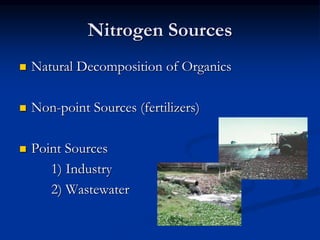
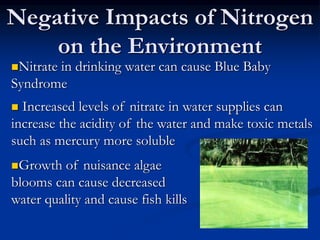
- Nitrogen sources include natural organic decomposition, fertilizers, and wastewater. Excess nitrogen harms the environment and water quality.
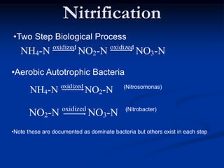
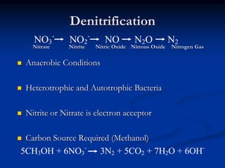
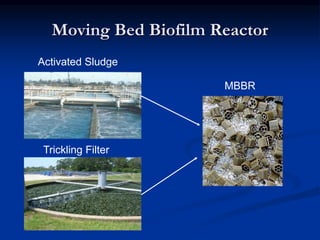
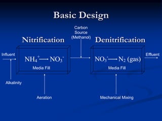
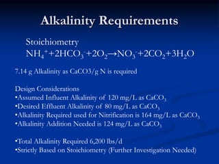
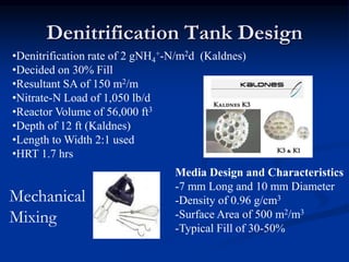
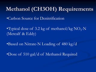
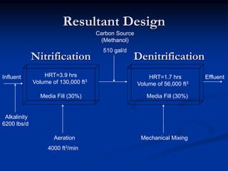
- The MBBR system uses aerobic and anaerobic bacteria attached to moving media for two-step nitrification and denitrification. This process converts ammonia to nitrate then nitrate to nitrogen gas.
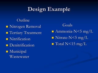
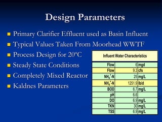
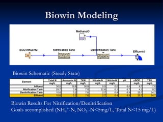
- An example design treats 6 million gallons per day of municipal wastewater to achieve nitrogen goals of ammonia/nitrate <5mg/L and total nitrogen <15mg/L. It includes a