The document provides extensive technical details about the UH-1H Huey helicopter, including its history, design specifications, major systems, flight characteristics, avionics, armaments, normal and emergency procedures. It describes the helicopter's engine and fuel systems, electrical and hydraulic systems, instrumentation, flight controls, communications and navigation equipment. Sections cover topics like take-off, hover, cruise flight, landing, autorotation, combat employment, special tasks like sling loads, and emergency procedures for failures like engine malfunctions or fires. Tables and diagrams are included to illustrate the helicopter's assembly, components, and cockpit layout.


![DIGITALCOMBATSIMULATORUH-1HHUEY
36
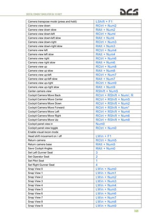
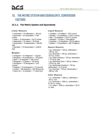
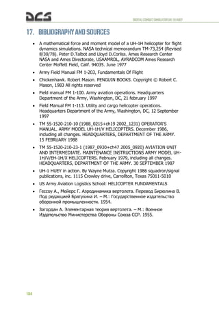
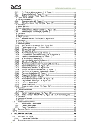
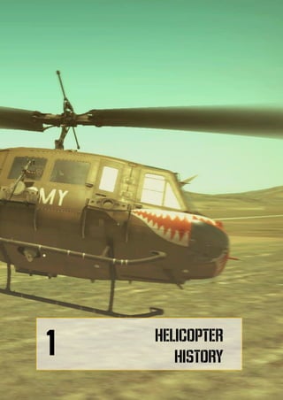
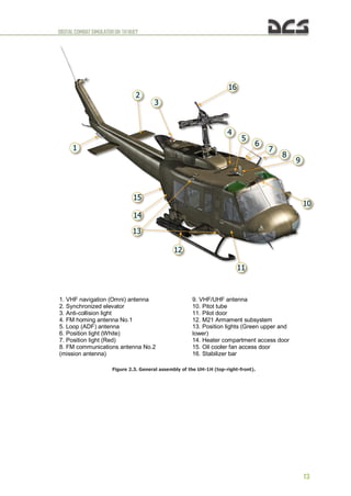
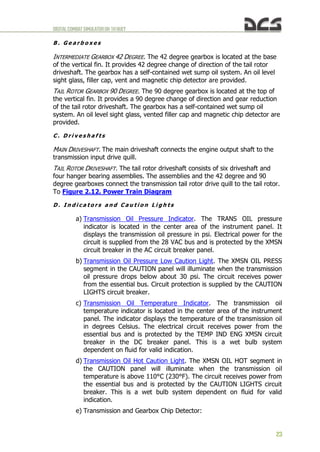
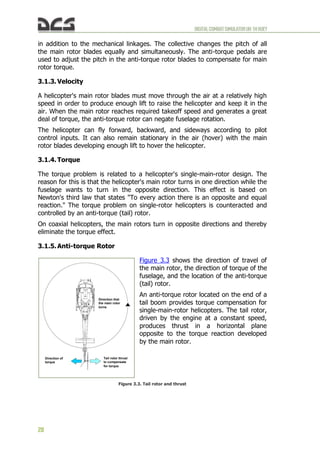
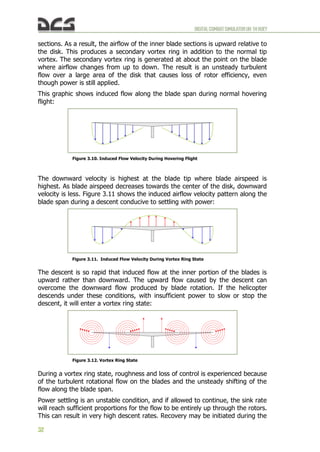
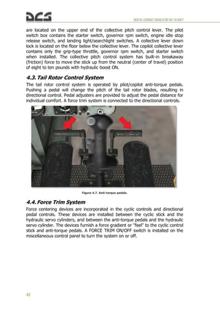
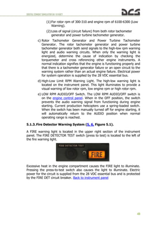
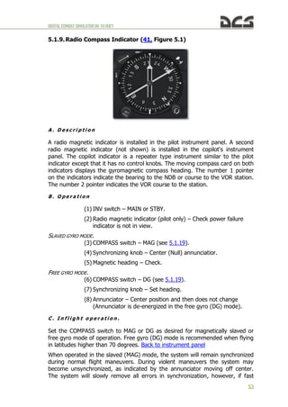
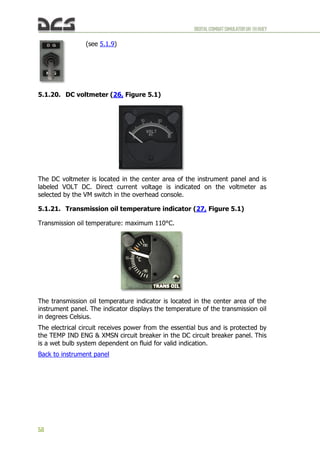
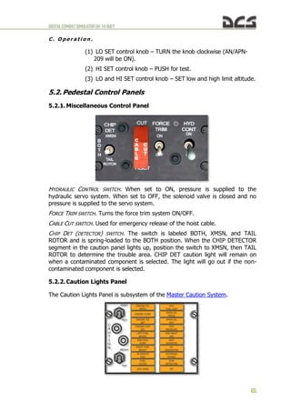
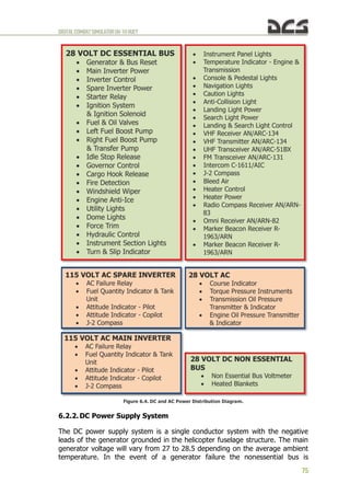
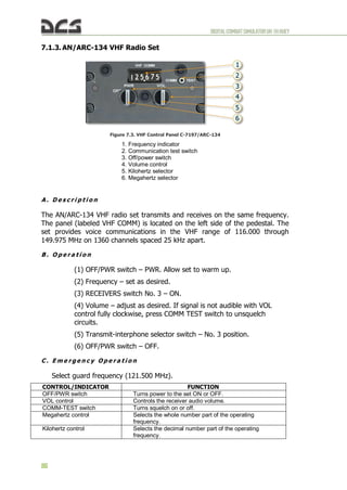
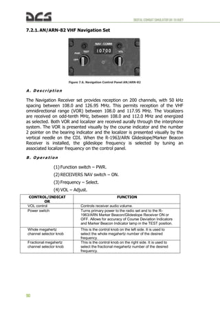
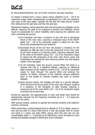
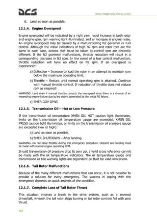
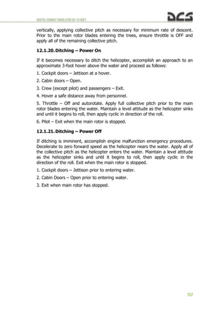
All helicopters carry an operator's manual that has an airspeed versus altitude
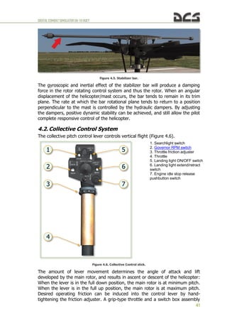
chart similar to the one shown in Figure 3.19. The shaded areas on this chart
must be avoided. This area is referred to as the "dead man's curve" and "avoid
curve". The proper maneuvers for a safe landing during engine failure cannot
be accomplished in these areas.
3.1.14. Summary
Weight, lift, thrust, and drag are the four forces acting on a helicopter. The
cyclic for directional control, the collective pitch for altitude control, and the
anti-torque pedals to compensate for main rotor torque are the three main
controls used in a helicopter.
Torque is an inherent problem with single-main-rotor helicopters. Gyroscopic
precession occurs at approximately 90° in the direction of rotation from the
point where the force is applied. Dissymmetry of lift is the difference in lift that
exists between the advancing and retreating halves of the rotor disc.
Settling with power can occur when the main rotor system is using from 20 to
100 percent of the available engine power, and the horizontal velocity is under
10 knots. At a hover, the rotor system requires a great volume of air upon
Figure 3.18. Autorotation Blade Forces
Axis of
Rotation
In driving or autorotative area In driven or propeller area
а а
VTA VTA
Rate of
descent
Rate of
descent
Resultant Resultant
Autorotative
force Anti-autorotative
force
Figure 3.19. Height-Velocity Diagram
Speed [km/h]
Height [m]
NOTE
Avoid continuous operation in indicated
areas. however, if the aircraft is operated in
the indicated areas, emergency procedures
relating to engine failures – low altitude,
low airspeed should be observed.](https://image.slidesharecdn.com/dcsuh-1hflightmanualen-231006033509-97bc74c0/85/DCS-UH-1H-Flight-Manual_EN-pdf-38-320.jpg)


![DIGITALCOMBATSIMULATORUH-1HHUEY
79
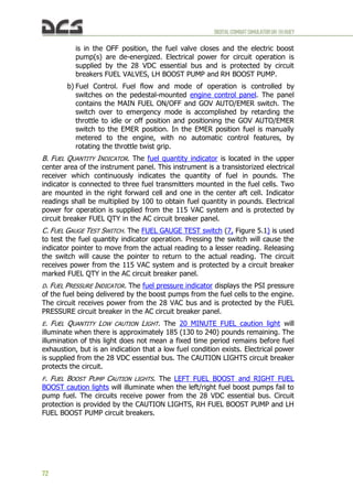
Electrical power for hydraulic system control is supplied by the 28 VDC essential
bus. The circuit is protected by the HYD CONT circuit breaker.
6.4. DE-ICE
Engine de-ice is a bleed air system activated by the DE-ICE switch on the
ENGINE control panel. In the ON position bleed air is directed through the
engine inlet to provide the protection. Power losses caused when the system is
on (auto increase rpm gas producer at 3..5%). In the event of DC electrical
failure or when the DE-ICE ENG circuit breaker is out, de-ice is automatically
ON. System power is provided by the DC essential bus and protected by the
ANTI-ICE ENG circuit breaker.
6.5. Game autopilot
Note. To simplify the use of helicopter-carried weapons when occupying other crew members'
positions (copilot, door gunners), helicopter is under control of a virtual pilot. This mode is
implemented as an autopilot. The game autopilot has three operation modes: ATTITUDE HOLD,
LEVEL FLIGHT, ORBIT.
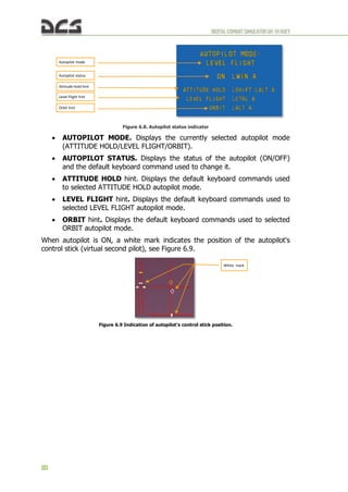
ATTITUDE HOLD – autopilot maintains all flight parameters that have been
established right before turning on the autopilot (roll, pitch, direction, without
stabilization of altitude and speed);
LEVEL FLIGHT – autopilot maintains speed, direction and altitude. If on
autopilot start time there was non-zero bank angle, it gets reduced to zero;
ORBIT – autopilot maintains constant turns with a roll of 13° at a constant
speed without descending. If on autopilot start time there was a greater bank
angle – it gets reduced down to 13°. If existing speed does not allow for such
turn without descend, then speed gets lowered to the maximum speed at which
the helicopter flies without descending.
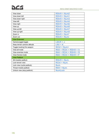
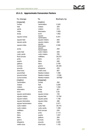
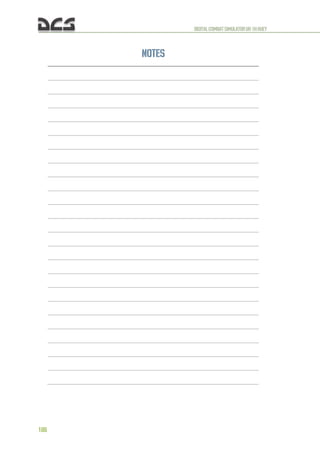
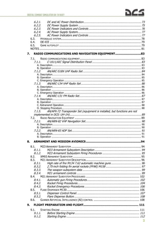
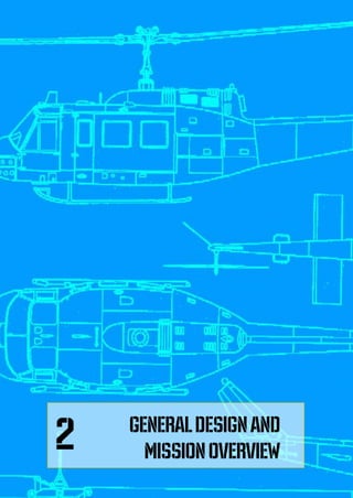
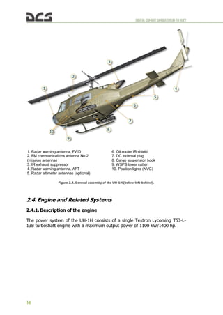
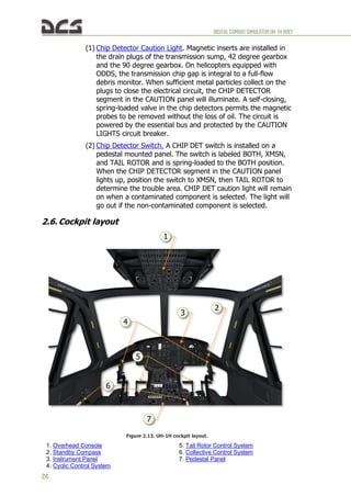
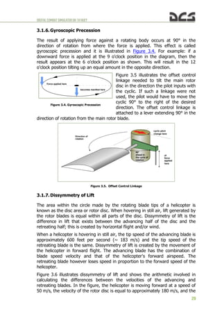
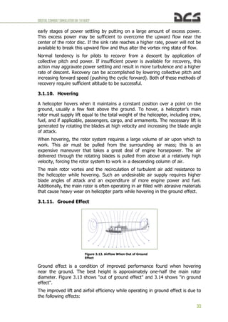
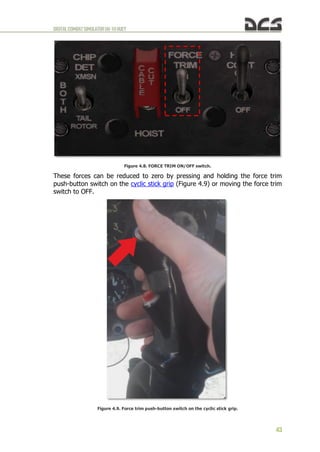
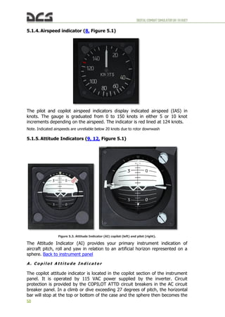
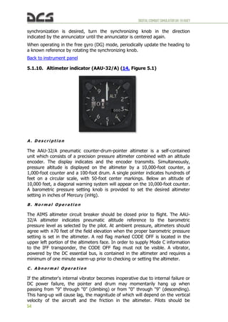
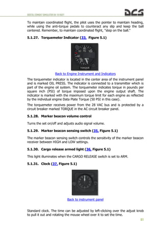
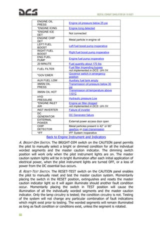
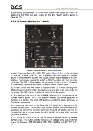
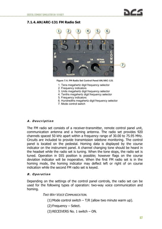
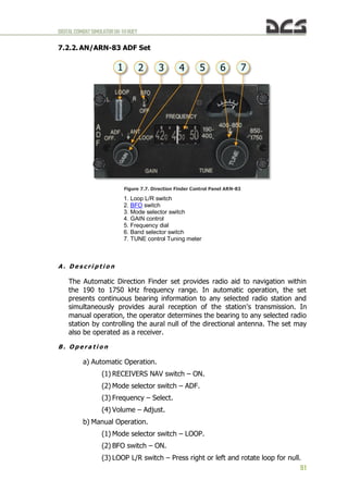
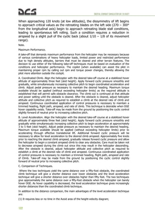
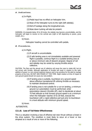
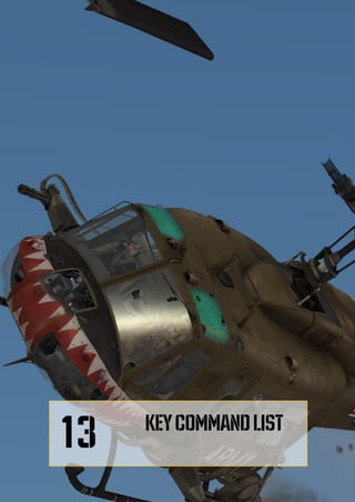
DCS: UH-1H includes a special weapon systems and autopilot status indicator
on the right side of the screen to help quickly assess the status of your weapon
systems and autopilot modes, as well as get quick hints of the keyboard
commands required to operate them. The display can be turned on and off by
pressing [LCTRL+LSHIFT+H]. See Figure 6.7, Figure 6.8.
Figure 6.7. Location of autopilot and weapon status indicators on screen.](https://image.slidesharecdn.com/dcsuh-1hflightmanualen-231006033509-97bc74c0/85/DCS-UH-1H-Flight-Manual_EN-pdf-81-320.jpg)


![DIGITALCOMBATSIMULATORUH-1HHUEY
95
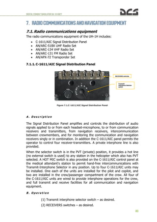
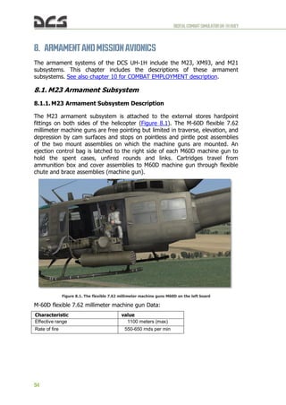
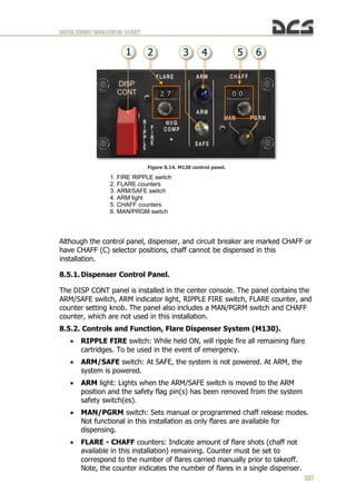
8.1.2. M23 Armament Subsystem Firing Procedures
To use the side door M-60D machines guns of the M23 armament subsystem,
first press [3] to take the position of the left door gunner or [4] to take the
position of the right door gunner.
Two aiming modes are available and can be set in the OPTIONS > SPECIAL >
UH-1H menu: Camera Aiming ON and Camera Aiming OFF.
With Camera Aiming ON, the gun/gunsight is latched to the view camera,
allowing you to aim with the mouse. To fire the gun, press the left mouse
button or [Space]. You can toggle mouse-look and mouse-click mode by
pressing [LAlt+C]. Note that you can use the mouse wheel to zoom the view in
and out, as well as adjust the 3D position of the view by holding the mouse
wheel down while moving the mouse.
With Camera Aiming OFF, the mouse or the keyboard numpad control the
camera, while the [;], [,], [.], [/] keys control the gun aim.
When you switch to a gunner's position, the currently selected autopilot mode
will be engaged to maintain helicopter flight control. The autopilot can be
turned on and off manually by pressing [LWIN+A].
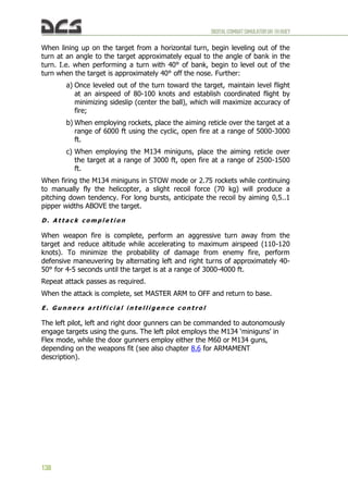
8.2. XM93 Armament Subsystem
Somewhat different from the M23 armament subsystem in design, but similar in
function, the XM93 armament subsystem is a door pintle mount for the M134
7.62mm "minigun", providing the door gunners the ability to operate the rapid-
firing M134 in place of the M23’s M60D machine guns. One XM93 platform can
be mounted in either door. Each platform is provided with 3200 rounds of
ammunition. Operation of the XM93 armament subsystem is identical to the
M23 subsystem as described above in section 8.1.2.](https://image.slidesharecdn.com/dcsuh-1hflightmanualen-231006033509-97bc74c0/85/DCS-UH-1H-Flight-Manual_EN-pdf-97-320.jpg)

![DIGITALCOMBATSIMULATORUH-1HHUEY
104
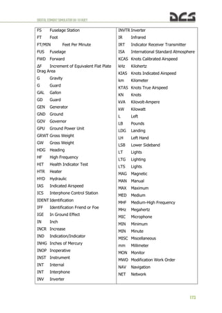
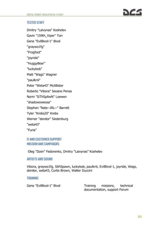
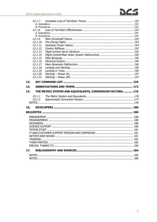
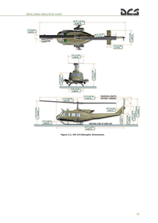
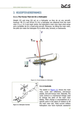
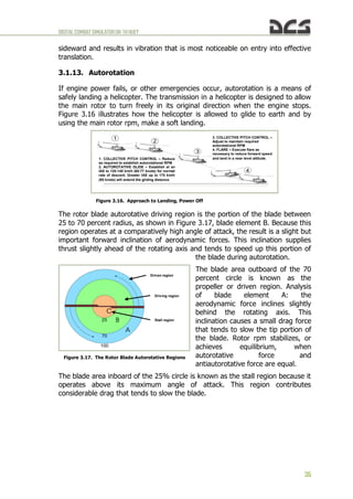
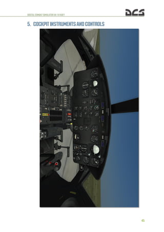
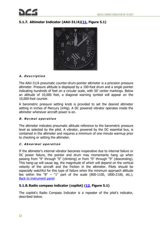
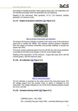
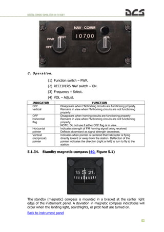
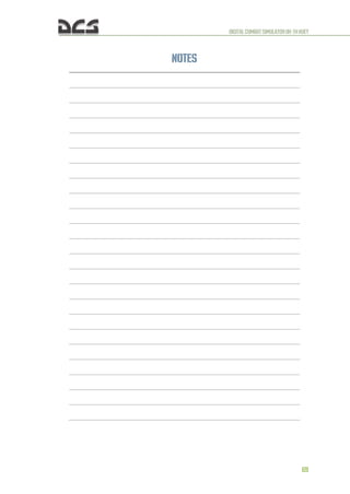
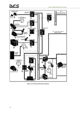
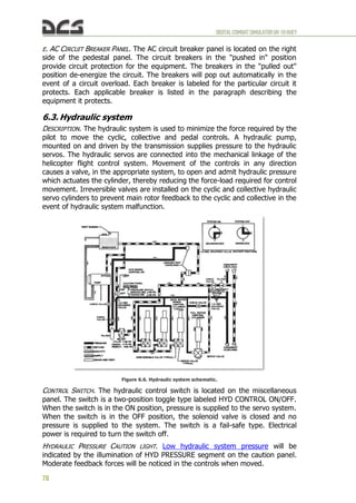
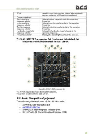
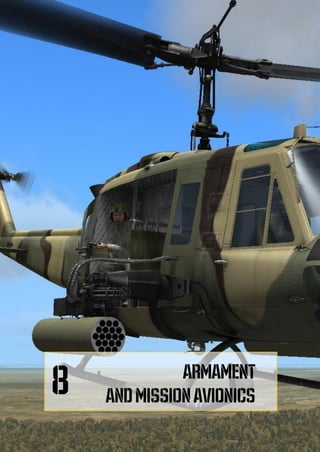
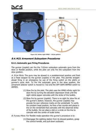
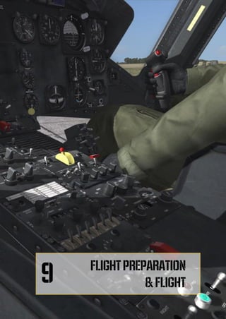
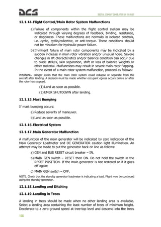
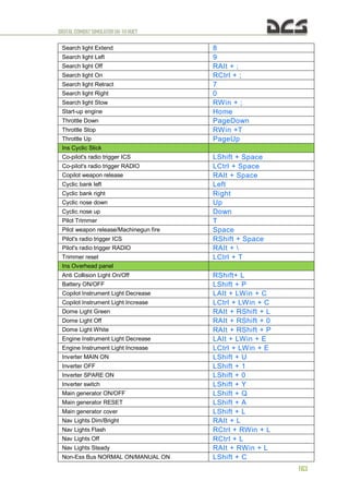
Figure 8.11. Sighting station. Demo FLEXIBLE MODE (2 of 2)
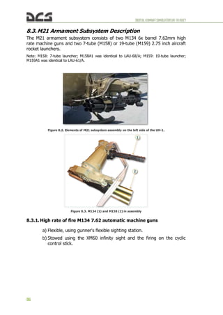
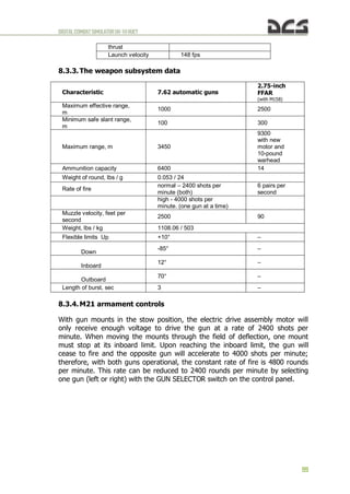
8.4.2. Rocket Firing Procedures
The 2.75-inch rocket launchers are fixed to the support assembly and can only
be fired from the stow position. When the armament selector switch is
positioned at 2.75, the primary subsystem mode is rocket firing by means of
cyclic stick firing switches. However, automatic gun firing can still be
accomplished by using the flexible sighting station. While firing rockets, the
automatic gun firing will be interrupted as long as the cyclic stick firing switch is
depressed. Rocket firing procedures are as follows:
A. BEFORE TAKEOFF.
1. Close the 7.62mm, rocket jettison, and XM60 sight circuit breakers.
2. Position the OFF-SAFE-ARMED switch to SAFE and check to see that the
green SAFE indicator light illuminates.
3. Position the armament selector switch to 7.62. This will prevent
accidental rocket firing before takeoff.
4. Check to ensure that the rocket PAIR SELECTOR switch is indicating
zero pairs.
5. Depress the RESET switch to reset the firing switch on each rack and
support assembly.
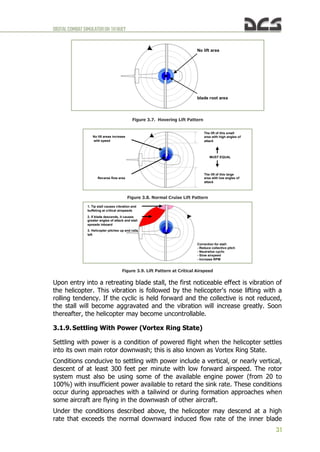
6. Conduct an operational check of the XM60 infinity sight as follows:
a) Depress the locking lever to disengage the sight from the stow
indent [LMouse click] or [RShift+M] (see Figure 8.7, Figure 8.12),](https://image.slidesharecdn.com/dcsuh-1hflightmanualen-231006033509-97bc74c0/85/DCS-UH-1H-Flight-Manual_EN-pdf-106-320.jpg)
![DIGITALCOMBATSIMULATORUH-1HHUEY
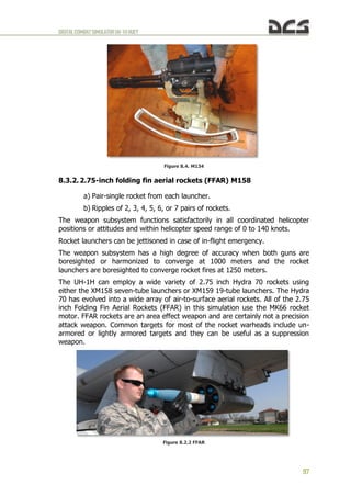
105
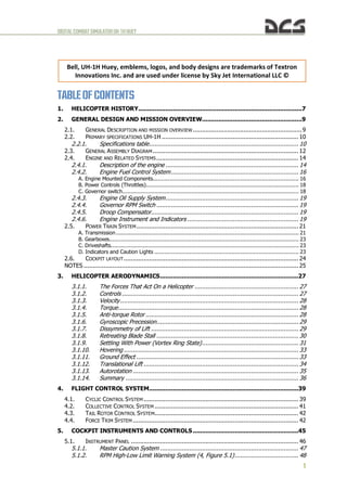
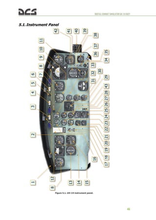
then swing the sight outboard and down from its stowed position
until the locking lever engages the operate indention.
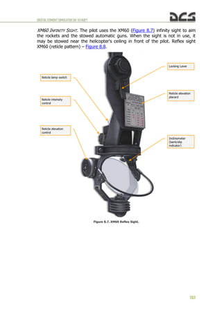
Figure 8.12. The locking lever of the XM60 infinity sight.
b) Move the reticle lamp switch either forward or aft of the center off
position to illuminate the reticle lamp [RCtrl+M].
c) Turn the rheostat knob to set reticle light intensity to desired level:
Intensity Decrease – [LAIt + X], Intensity Increase – [LCtrl + X] (or
turn mouse wheel).
d) Set desired Sight Elevation at the fixed index scale on the sight:
Elevation Decrease – [LAIt + S], Elevation Increase – [LCtrl + S] (or
turn mouse wheel) (see Figure 8.7, Figure 8.13).
Figure 8.13. Reticle elevation control.](https://image.slidesharecdn.com/dcsuh-1hflightmanualen-231006033509-97bc74c0/85/DCS-UH-1H-Flight-Manual_EN-pdf-107-320.jpg)

![DIGITALCOMBATSIMULATORUH-1HHUEY
108
Two dispensers are carried and fire flares simultaneously. As such, the
actual number of flares carried is twice the indicated number in the
FLARE counter.
8.5.2. Flare Dispense Button.
Figure 8.3 M130 Flare Dispense button
The FLARE DISPENSE button is used to release flares when the M130
countermeasures system is armed. A single press of the button fires a single
flare from each dispenser, of which two are equipped. Holding the button down
fires a single flare from each dispenser every 3 seconds.
8.6. Gunner Artificial Intelligence (AI) control
The left pilot, left and right door gunners can be set to autonomously engage
targets of opportunity. The left pilot engages targets with the M134 miniguns in
Flex mode, while the door gunners engage targets using either the M134 door
gun or the M60D door gun, depending on the payload profile. Turning on AI
gunners requires setting the Rules of Engagement (ROE) mode for the desired
gunner. In addition, the firing burst length can be set between Short and Long
burst. These and other parameters can be monitored on the CREW STATUS
INDICATOR.
Figure 8.16 Crew Status Indicator
HEALTH. The HEALTH column indicates the alive (green) or out of
action (red) state of each crew member.
ROE. The ROE column indicates the current ROE setting for each
gunner. The setting can be cycled between HOLD, RET. FIRE (return
fire) and FREE FIRE. To cycle the ROE setting, press [LCtrl + 2],
[LCtrl+3], [LCtrl + 4] for the left pilot, left door gunner, and right door
gunner, respectively. Additionally, the ROE column indicates which
position is currently taken by the player.](https://image.slidesharecdn.com/dcsuh-1hflightmanualen-231006033509-97bc74c0/85/DCS-UH-1H-Flight-Manual_EN-pdf-110-320.jpg)
![DIGITALCOMBATSIMULATORUH-1HHUEY
109
AMMO. The AMMO column indicates the amount of rounds remaining in
percent for each gunner weapon.
BURST. The BURST column indicates the current burst length setting for
each gunner. The setting can be cycled between SHORT and LONG by
pressing [LShift + 2], [LShift + 3], [LShift + 4] for the left pilot, left
door gunner, and right door gunner, respectively.
The gunners’ reaction time and aiming accuracy is determined by the Gunners
AI Skill slider in the player-controlled UH-1H Helicopter Group properties menu.
Figure 8.17 Gunners AI Skill slider.](https://image.slidesharecdn.com/dcsuh-1hflightmanualen-231006033509-97bc74c0/85/DCS-UH-1H-Flight-Manual_EN-pdf-111-320.jpg)
![DIGITALCOMBATSIMULATORUH-1HHUEY
111
9. FLIGHTPREPARATIONAND FLIGHT
9.1. Starting Engine
AUTO START ENGINE [LWIN+Home].
9.1.1. Before Starting Engine
1. Overhead switches and circuit breakers – Set as follows:
a) DC circuit breakers – IN, except for armament and special
equipment.
b) DOME LT switch – As required.
c) AC POWER switches – Set as follows:
(1) PHASE switch – AC [LShift+R].
(2) INVTR switch – OFF [LShift+I].
d) DC POWER switches – Set as follows:
(1) MAIN GEN switch – ON and cover down [LShift+Q].
(2) VM selector – ESS BUS [LShift+H].
(3) NON-ESS BUS switch – As required.
(4) STARTER GEN switch – START [LShift+X].
(5) BAT switch – ON [LShift+P].
2. Ground power unit – Connect for GPU start.
3. FIRE warning indicator light – Test [RCtrl+T].
4. Center pedestal switches – Set as follows:
a) Avionics equipment – Off; set as desired.
b) External stores jettison handle – Check safe tied.
c) DISP CONTROL panel – Check ARM/STBY/SAFE switch is SAFE
[RShift+RAlt+L]; check that JETTISON switch [LAlt+J] is down and
covered.
d) GOV switch – AUTO [G].
e) DE-ICE switch – OFF [I].
f) FUEL switches – Set as follows:
(1) MAIN FUEL switch – ON [F].
(2) All other switches – OFF.
g) Caution panel lights – TEST [LAlt+R] and RESET [R].
h) HYD CONT switch – ON [LAlt+I].
i) FORCE TRIM switch – ON [LAlt+U].
j) CHIP DET switch – BOTH [LAlt+G].](https://image.slidesharecdn.com/dcsuh-1hflightmanualen-231006033509-97bc74c0/85/DCS-UH-1H-Flight-Manual_EN-pdf-113-320.jpg)
![DIGITALCOMBATSIMULATORUH-1HHUEY
112
5. Flight controls – Check freedom of movement through full travel: center
cyclic and pedals; collective pitch full down.
6. Altimeters – Set to field elevation
FOR PILOT: pressure decrease – [RCtrl+B];
pressure increase – [RShift+B];
FOR COPILOT: pressure decrease – [LCtrl+B];
pressure increase – [LShift+B];
9.1.2. Starting Engine
1. Turn on the Controls Indicator by pressing [RCTRL + ENTER].
2. Throttle – Set for start. Position the throttle as near as possible (on
decrease side) to the engine idle stop position. To do so:
a) Roll the throttle fully left (increase) (Figure 9.1) from FULL CLOSE
(Figure 9.2, 1) to FULL OPEN position by pressing and holding
[PgUp].
b) Roll the throttle back to the right (decrease) by pressing and holding
[PgDn] until the idle stop (Figure 9.2, 2) is reached and the throttle
cannot rotate further past the detent.
c) Press [RWIN + T] to engage the IDLE RELEASE switch on the
collective control box.
d) Press [PgDn] to roll the throttle just right (decrease) of the idle
position. The throttle will now be set as near as possible (on
decrease side) to the engine idle stop position as required for engine
start.
e) Press [RWIN + T] again to release the IDLE RELEASE switch on the
collective control box.
Figure 9.1. Direction of rotation of the throttle
[PgUp]
roll left
(increase)
[PgDn]
roll right
(decrease)
Idle release
switch](https://image.slidesharecdn.com/dcsuh-1hflightmanualen-231006033509-97bc74c0/85/DCS-UH-1H-Flight-Manual_EN-pdf-114-320.jpg)
![DIGITALCOMBATSIMULATORUH-1HHUEY
113
1. FULL CLOSE position 2. IDLE STOP position
Figure 9.2. FULL CLOSE and IDLE STOP position
3. Engine – Start as follows:
a) Start switch – press and hold [Home]; note start time.
Note. DC voltmeter indication. Battery starts can be made when voltages less than 24 volts are
indicated, provided the voltage is not below 14 volts when cranking through 10 percent N1
speed.
b) Main rotor – Check that the main rotor is turning as N1 reaches 15
percent. If the rotor is not turning, abort the start.
c) Start switch – Release at 40 percent N1 or after 40 seconds,
whichever occurs first.
d) Throttle − Slowly advance past the engine idle stop ([PgUp]) to the
engine idle position. Manually check the engine idle stop by
attempting to close the throttle ([PgDwn]). Ensure the throttle is
kept in idle power as the engine is being spooled up.
Setting the throttle past idle during engine start can result in engine
damange or fire!
e) N1 68 to 72 percent. Hold a very slight pressure against the engine
idle stop during the check. A slight rise in N1 may be anticipated
after releasing pressure on throttle.
Note. The copilot attitude indicator should be caged and held momentarily as inverter power is
applied.
4. INVTR switch − MAIN ON [LShift+U].
5. Engine and transmission oil pressures − Check.
6. GPU − Disconnect.
9.1.3. Engine Runup
1. Avionics − ON.
2. STARTER GEN switch − STBY GEN [LShift+X].](https://image.slidesharecdn.com/dcsuh-1hflightmanualen-231006033509-97bc74c0/85/DCS-UH-1H-Flight-Manual_EN-pdf-115-320.jpg)

![DIGITALCOMBATSIMULATORUH-1HHUEY
124
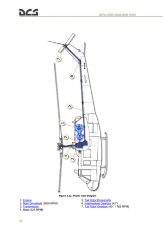
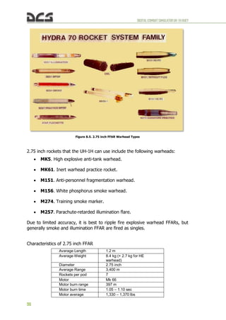
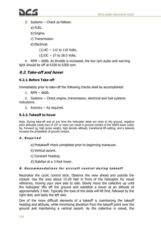
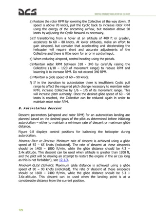
9.5. Descent and landing
When preparing for landing, the approach should be planned so that descent
and deceleration is performed against the wind or with a crosswind from the
right.
D e s c e n t
From a starting altitude of 400 – 450 ft, plan for an approach distance of 4500
– 5000 ft to the landing hover point. As experience builds, the approach
distance can be reduced to 3500 – 4000 ft. When flying a visual approach
pattern, the turn to final should be started when the touchdown point is
approximately 15 - 20° off the nose of the helicopter and performed with a
bank of 15 - 20° to start (Figure 9.8) the final approach at approximately 80
knots.
Figure 9.8. Lining up for final approach.
When descending for a landing, the glideslope can be approximated according
to the following guidelines:
Descent parameters
Distance 4500 - 4000 ft
(1500 m)
3000 ft
(1000 m)
1500 ft
(500 m)
Speed [knots] 80 60 40..30
Altitude [ft] 500..450 350..300 200..150
Descent [ft/min] 300..500 400..600 200..300
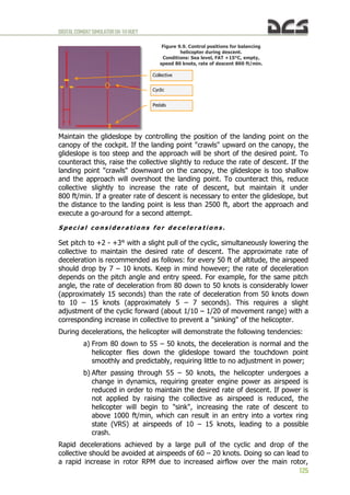
After completing the turn to final approach, set up and control the descent. As
the collective is lowered and the rate of descent reaches 500 – 600 ft/min, the
airflow dynamics over the elevator will tend to drop the nose down and
increase airspeed. To counteract this, pull the cyclic back about 1/8 – 1/6 of its
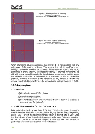
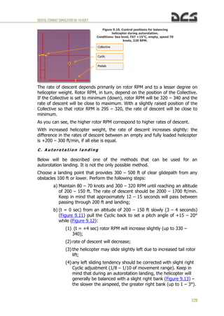
movement range. Figure 9.9 shows control positions for balancing the
helicopter during descent.](https://image.slidesharecdn.com/dcsuh-1hflightmanualen-231006033509-97bc74c0/85/DCS-UH-1H-Flight-Manual_EN-pdf-126-320.jpg)
![DIGITALCOMBATSIMULATORUH-1HHUEY
126
which can produce a number of negative consequences: engine governor
reduces engine power to compensate for increased rotor RPM; once airspeed
reaches 25 – 20 knots, the helicopter tends to "sink", requiring a rapid increase
in collective to prevent an uncontrolled descent; the engine is incapable of
providing the power required to maintain rotor RPM at the increased collective
setting rapidly enough; the increased collective setting combined with an
underpowered regime of the engine results in rotor underspeed (below 314
RPM); the helicopter begins a spontaneous descent the pilot is unable to stop; a
right yaw tendency may also appear as torque increases with increased engine
RPM and tail rotor effectiveness is reduced with lower rotor RPM.
In summary: the pilot has a margin of error when flying a landing approach
where he can deviate somewhat from the guidelines described above. However
this margin is reduced as the free air temperature (FAT) is raised, helicopter
weight is increased, and the pressure altitude of the landing site is increased.
L a n d i n g f r o m a H o v e r ( s e e 9 . 2 . 6 )
R u n - o n L a n d i n g
A run-on landing may be used during emergency conditions of hydraulic power
failure, some flight control malfunctions, and environmental conditions. The
approach is shallow and flown at an airspeed that provides safe helicopter
control. Airspeed is maintained as for normal approach except that touchdown
is made at an airspeed above effective translational lift. After ground contact is
made, slowly decrease collective pitch to minimize forward speed. If braking
action is necessary, the collective pitch may be lowered as required for quicker
stopping.
9.6. Engine Shutdown
AUTOSTOP ENGINE: [LWIN+End].
1. Throttle Engine idle for two minutes ([PgDown] for min position
throttle).
2. FORCE TRIM switch ON.
3. STARTER GEN switch START [LShift+X].
4. Throttle – Off. To rotate the throttle from IDLE to OFF, perform the
following steps:
5. Press [RWIN + T] to engage the idle stop release.
6. Press and hold [PgDn] to roll the throttle fully right (decrease) until it
reaches the OFF position and fuel flow to the engine is cut off.
7. Center Pedestal switches Off:
a) FUEL [F] (in this game, the engine stops).
b) Avionics.
8. Overhead switches Off:
a) INVTR [LShift+I].](https://image.slidesharecdn.com/dcsuh-1hflightmanualen-231006033509-97bc74c0/85/DCS-UH-1H-Flight-Manual_EN-pdf-128-320.jpg)
![DIGITALCOMBATSIMULATORUH-1HHUEY
127
b) PITOT HTR [RAlt+P].
c) LTS: Navigation lights [RCtrl+L], Landing light [RCtrl+,], Search
light [RAlt+;].
d) MISC (switches of miscellaneous Control Panel).
e) INST LTG.
9. BAT [LShift+P].
9.7. Autorotation. Practical part
An autorotation (theory – see 3.1.13) is used to land the helicopter in a variety
of situations where normal flight control becomes impossible. Among these may
be a malfunction or complete failure of the engine, tail rotor system, tail rotor
drive system, or other problems requiring minimizing torque from the main
rotor. The UH-1H has excellent autorotation characteristics, which helps
perform autorotation landings safely. This is made possible by the low disc
loading of the main rotor – from 3.90 lbs/ft² (19 kg/m²) for an empty
helicopter up to 5.24 lbs/ft² (25.5 kg/m²) for a fully loaded helicopter1
, as well
as a heavy main rotor that carries a lot of inertia and potential energy. Here is
how these factors were described by the UH-1 pilot Robert Mason in his book,
Chickenhawk:
“The heavy, thudding noise of the main rotors – the characteristic wop-wop-wop sound – was
caused by their huge size, 48 feet from tip to tip, and a 21-inch chord (width). With ballast
weights at each blade tip, the whirling rotor system had tremendous inertia. The IP
demonstrated this inertia with a trick that only a Huey could do. On the ground at normal rotor
speed (330 rpm) he cut the power, picked the machine up to a four-foot hover, turned
completely around, and set it back on the ground. Incredible! Any other helicopter would just
sit there, not rising an inch, while the rotors slowed down. These big metal blades with the
weights in the tips would serve me well in Vietnam. Their strength and inertia allowed them to
chop small tree branches with ease”.
Because of these design features, learning to perform autorotation landing on
the Huey is considerably easier than on most other helicopter types.
A . T r a n s i t i o n i n g t o a u t o r o t a t i o n
Typically the need to perform an autorotation arises suddenly while the pilot is
focused on flight tasks not directly related to managing the power system. For
example these might be: conducting visual scanning, maintaining formation,
weapons employment, etc. Experience has shown that it can take from 2 to 5
seconds between a system malfunction and the start of corrective actions by
the pilot. A safe autorotation landing begins with a timely recognition of the
problem and immediate, appropriate control actions to transition into
autorotation.
The greatest RPM drop occurs in cases of a complete engine failure during level
flight with velocity above 80 knots or climb. A corrective control lag of 2-5
seconds can result in rotor RPM dropping to 280. In such cases, immediately
perform the following steps:
1
As a comparison, the disc loading of the AH-64D is 5.95 lbs/ft2
(29 kg/m2
) for an empty helicopter and
11.61 lbs/ft2
(56.7 kg/m2
) when fully loaded.](https://image.slidesharecdn.com/dcsuh-1hflightmanualen-231006033509-97bc74c0/85/DCS-UH-1H-Flight-Manual_EN-pdf-129-320.jpg)


![DIGITALCOMBATSIMULATORUH-1HHUEY
134
10. COMBATEMPLOYMENT
This chapter includes a description of UH-1H combat employment, see also
chapter 8 for ARMAMENT description.
As described in chapter 8, in addition to the two M60D door gunner machine
guns, the UH-1H can be armed with two XM158 rocket pods with 7 70mm
unguided rockets each (or XM159 pods with 19 rockets each) and two M134 6-
barrel Gatling type Miniguns with 5400 rounds total. Unless noted otherwise,
the remainder of the chapter will assume a standard combat load of 2xXM158 +
2xM134.
When learning to fly and employ the weapon systems, it is recommended that
you enable the WEAPON STATUS indicator in the Options/Special/UH-1H page
of the game menu Figure 10.1..Figure 10.3 (remove/display WEAPON STATUS
indicator together in hint AUTOPILOT MODE from/on the screen
[LShift+LCtrl+H]).
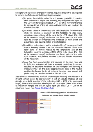
Figure 10.1. Location of the WEAPON STATUS indicators.
Figure 10.2. Weapon systems status indicator: OFF (not firing), 7.62 (M134 active weapon), 6400
(current balance cartridges), BOTH (fire simultaneously from two guns).
Available weapons
Master Arm setting
Active weapon
Fire settings](https://image.slidesharecdn.com/dcsuh-1hflightmanualen-231006033509-97bc74c0/85/DCS-UH-1H-Flight-Manual_EN-pdf-136-320.jpg)
![DIGITALCOMBATSIMULATORUH-1HHUEY
135
Figure 10.3. Weapon systems status indicator: ARMED (ready to open fire), 2.75 (XM158 active weapon),
38 (current balance rockets), X2 (two rockets from each launcher when you press the button once).
A . F l i g h t c o n t r o l
When the helicopter is loaded with the standard combat load, the center of
gravity (CG) shifts forward. This results in a greater amount of stick back
pressure (pull) required by during takeoff and hover (1/3 – 1/4 of its movement
range). Similarly, balanced forward flight is established with approximately 1/3
– 1/4 less forward stick than usual.
B . C o c k p i t p r o c e d u r e s
Weapon systems are turned on prior to entering the combat area.
EMPLOYING THE XM158 (XM159) WEAPON SYSTEM (ROCKETS):
a) Select the desired cockpit position (pilot or copilot) – [1], [2];
b) Select "2.75" on the armament control panel – [RALT+[ ];
c) Set the desired number of rocket pairs to be fired on the armament
control panel (1 to 7 from each launcher) – [RCTRL+] ] and
[RCTRL+[ ];
d) Establish coordinated flight with minimizing descent (climb) and by
minimizing sideslip (center the ball), which will maximize accuracy of
fire;
e) Set the aiming sight – [M] for left pilot’s Flex sight or [RSHIFT+M]
for the right pilot’s XM60 Reflex sight. If playing as pilot (right
side), you may need to turn on the reticel lamp by pressing
[RCTRL+M]. The aiming reticle will appear (Figure 10.4). If playing](https://image.slidesharecdn.com/dcsuh-1hflightmanualen-231006033509-97bc74c0/85/DCS-UH-1H-Flight-Manual_EN-pdf-137-320.jpg)
![DIGITALCOMBATSIMULATORUH-1HHUEY
136
as copilot (left side), the flexible sight will move down and the sight
reticle will appear (Figure 8.10);
f) Turn on the MASTER ARM switch – [RSHIFT+] ] twice.
The helicopter is now prepared for rocket employment.
Figure 10.4. XM60 Reflex sight reticle turned on.
When autopilot is engaged, the “Autopilot: ON” indication is added to the
Weapons Status Indicator.
When playing as copilot (left side) and Flexible Mode is active, the autopilot is
engaged automatically. This is designed to simulate the pilot maintaining the
helicopter's attitude while the player operates the weapon system. The
autopilot can be manually turned on and off with the [LWIN+A] key. The
autopilot engages whenever the following conditions are true:
a) Flexible Mode is active;
b) The OFF-SAFE-ARMED switch is in the ARMED position.
Whenever the autopilot is engaged, the "Autopilot: ON" indication is added to
the Weapons Status Indicator.](https://image.slidesharecdn.com/dcsuh-1hflightmanualen-231006033509-97bc74c0/85/DCS-UH-1H-Flight-Manual_EN-pdf-138-320.jpg)
![DIGITALCOMBATSIMULATORUH-1HHUEY
137
EMPLOYING THE M134 WEAPON SYSTEM (MINIGUNS):
a) Select the desired cockpit position (pilot or copilot) – [1], [2];
b) Select "7.62" on the armament control panel – [RALT+] ];
c) Set the gun selector on the armament control panel to LEFT, RIGHT,
or ALL as desired – [RAlt+RCtrl+] ], [RAlt+RCtrl+[ ];
d) Set the aiming sight – [M] for left pilot’s Flex sight or [RSHIFT+M]
for the right pilot’s XM60 Reflex sight. If playing as pilot (right
side), you may need to turn on the reticel lamp by pressing
[RCTRL+M]. The aiming reticle will appear (Figure 10.4). If playing
as copilot (left side), the flexible sight will move down and the sight
reticle will appear (Figure 8.10);
e) Turn on the MASTER ARM switch – [RSHIFT+ ] ] twice (see above).
The helicopter is now prepared for employment of the M134
miniguns.
Two aiming modes are available and can be set in the OPTIONS > SPECIAL >
UH-1H menu: Camera Aiming ON and Camera Aiming OFF.
With Camera Aiming ON, the gun/gunsight is latched to the view camera,
allowing you to aim with the mouse. To fire the gun, press the left mouse
button or [Space]. You can toggle mouse-look and mouse-click mode by
pressing [LAlt+C]. Note that you can use the mouse wheel to zoom the view in
and out, as well as adjust the 3D position of the view by holding the mouse
wheel down while moving the mouse.
With Camera Aiming OFF, the mouse or the keyboard numpad control the
camera, while the [;], [,], [.], [/] keys control the gun aim.
C . L i n i n g u p , a i m i n g , a n d f i r i n g
Attempt to enter the target area undetected by maintaining nap-of-the-earth
flight to the target area and avoid known air defense positions. When
approaching to within 9000-8000 ft of the target, climb to acquire the target.
The climb can be performed either by pulling the cyclic to raise the nose to a
pitch angle of 10-15° or by increasing collective to gain altitude while
maintaining pitch angles. The latter method is preferable as it maintains the
target in view in front of the helicopter, prevents an increase of the helicopter's
silhouette for enemy defenses, and minimizes loss of airspeed in the climb.
After completing the climb, confirm the target's location and maneuver the
helicopter to face the target.](https://image.slidesharecdn.com/dcsuh-1hflightmanualen-231006033509-97bc74c0/85/DCS-UH-1H-Flight-Manual_EN-pdf-139-320.jpg)
![DIGITALCOMBATSIMULATORUH-1HHUEY
142
It’s needed to select the one, perform hooking, take off, flight to the designated
unhooking area, approach the unhooking point and unhook the cargo.
PLAYER’S ACTIONS.
S e l e c t i o n o f c a r g o
For making the cargo selection possible the “cargo selection zone” was
implemented. That zone is connected to and moves with player’s or AI
helicopter (marked as a circles around helicopters No.1 and No.2). Thus cargos
can be selected by player being inside mentioned zone only – at a distance less
than “cargo selection zone” radius (see Figure 11.3, helicopter No.2)
Figure 11.3. Cargo selection menu appearance depandant on distance to cargo..
Based on the testing experience, the “cargo selection zone” radius is set to
2,000m (6,562ft). If a helicopter is more than 2,000m away from the cargos,
no cargo can be selected (helicopter menu #1). As soon as any cargo gets into
the “cargo selection zone”, which moves with the helicopter, a new menu item
appears and additional page containing the list of cargos can be activated: [ ]
- > [F6] (helicopter menu #2). Now player can select any cargo from a list (see
Figure 11.4):](https://image.slidesharecdn.com/dcsuh-1hflightmanualen-231006033509-97bc74c0/85/DCS-UH-1H-Flight-Manual_EN-pdf-144-320.jpg)
![DIGITALCOMBATSIMULATORUH-1HHUEY
143
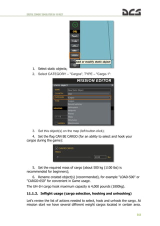
Figure 11.4. Menu for select of cargo.
1. Selection key
2. Name of cargo
3. True weight of carg
To select a cargo player needs to press one of the keys [F1…F10].
Simultaneously the cargo location will be marked with a smoke (white or red).
Smoke marker will be visible only for the player who has selected this cargo
(see Figure 11.5):
Figure 11.5. Auto designation of cargo smoke marker.
H o o k i n g t h e c a r g o
After cargo selection the player has two options of picking it up. The first one
(automatic) is from hovering above the cargo, the second one (manual, i.e. by
player command) – landing near by. When the first option is used, the function](https://image.slidesharecdn.com/dcsuh-1hflightmanualen-231006033509-97bc74c0/85/DCS-UH-1H-Flight-Manual_EN-pdf-145-320.jpg)
![DIGITALCOMBATSIMULATORUH-1HHUEY
144
of automatic cargo hooking is activated (given the hovering is performend in
needed manner, see below). If the second option is used, cargo gets hooked by
key command when player landed close enough the selected cargo.
The cargo selection can be cancelled by the command menu: [ ] -> [F6] ->
[F1] . After this, by using [ ] -> [F6] all the cargos within a 2,000m radius will
again be available.
To help the player to determine the required flight direction towards the cargo
and also the helicopter location above the cargo, a cargo display can be
activated [LShift+LCtrl+C], which is a virtual camera directed downwards
perpendicular to the horizon. The camera does not take into account the roll
and pitch deflections. It considers the heading alterations only. Also it has a
marker of azimuth cargo position (see Figure 11.6).
Figure 11.6. Display cargo position.
1. Smoke marker
2. Cargo position display
3. Marker of cargo position
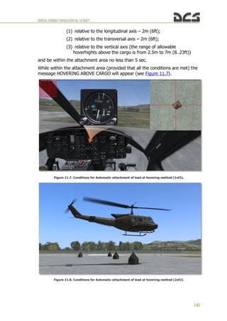
To lift off cargo from the surface the helicopters hovering altitude should be at
least 8.96m (radioaltimeter indications must be at least 30 ft).
AUTOMATIC ATTACHMENT OF CARGO (CARGO HOOKED) actuates if the actuates if the
player meets several conditions, which take into account the rope suspension
length (7m or 23ft), the accuracy of the hovering position and the interval
necessary for a virtual hookup man to hook the load. Therefore, in order to
carry out an automatic attachment of cargo it is necessary to hover within a
specified time lapse in a certain area above the cargo with the deviations from
the center no more than:](https://image.slidesharecdn.com/dcsuh-1hflightmanualen-231006033509-97bc74c0/85/DCS-UH-1H-Flight-Manual_EN-pdf-146-320.jpg)
![DIGITALCOMBATSIMULATORUH-1HHUEY
146
In case you are out of the attachment area, the message BEYOND ZONE OF
HOVERING will appear. Once the cargo is automatically attached, the message
CARGO HOOKED will appear.
While hovering above the cargo using the camera it is recommended to use it
only by peripheral vision with your attention being focused on the surface
before the helicopter in a sweeping glance so as to maintain the hovering
position more accurately from displacements relative to the longitudinal and
transversal axes.
MANUAL ATTACHMENT OF CARGO (CARGO HOOKED) is carried out by player’s command
[RShift+RCtrl+L] after landing near the cargo (the distance from the
helicopter center is no more than 5m or 16ft), see Figure 11.9.
Figure 11.9. Cargo hooked (landing method).
As a result of attaching cargo a rope suspension appears. The cargo selection
can be cancelled by the command menu: [ ] -> [F6] -> [F1] . After this, by
using [ ] -> [F6] all the cargos within a 2,000m radius will again be available.
T a k e o f f w i t h a s l i n g l o a d
Upon receiving the message CARGO HOOKED, take off vertically with the sling
load. Perform the vertical climb up to the height so as the cargo is higher no
less than 5m (15ft) than hazards in the runway heading. After the climb without
hover locking accelerate to 60 KNOTS and continue the climb to the specified
value.
F l i g h t t o t h e u n h o o k e d a r e a
After the climb put the helicopter over at the speed of 60..100KNOTS. During
the flight when the cargo swing occurs, damp out oscillations:
when the roll oscillations occurs – make a small roll movement in the
same direction where the cargo is moving or reduce a little the collective
pitch at the moment when the cargo is close to one of the end points;](https://image.slidesharecdn.com/dcsuh-1hflightmanualen-231006033509-97bc74c0/85/DCS-UH-1H-Flight-Manual_EN-pdf-148-320.jpg)
![DIGITALCOMBATSIMULATORUH-1HHUEY
147
when the pitch oscillations occurs – reduce a little the collective pitch at
the moment when the cargo is close to one of the end points.
A p p r o a c h t o t h e a r e a o f t h e l o a d d e t a c h m e n t , d e t a c h m e n t o f
l o a d ( c a r g o u n h o o k )
You should approach the area of the load detachment much smoother than
during the usual flight. Mark visually the hovering position and reference points
(2..3) at the distance of 10..30m (30..100ft) from the hovering position to make
it easier to keep to the hovering position. These reference points must be seen
from the cockpit during the hovering. It is recommended to keep in sight the
chosen reference points by sweeping motion of the eyes so as you could timely
correct even the initial helicopter displacement tendencies. It is necessary to
perform SHORT TWOFOLD MOTIONS BY THE CYCLIC CONTROL STICK (amplitude is
0.5..1cm, motion rate is 1.5..2Hz) for more precise piloting.
For more comfortable load detachment you can activate the load automatic
detachment function [RShift+RCtrl+K]. This will provide for an automatic
detachment of the cargo when it touches down the surface. The automatic
detachment is accompanied by the message AUTOUNHOOK ACTIVATION.
Likewise, the cargo can be unhooked after landing near the cargo (the same
key commands).
11.2. Helicopter assault (airlift delivery)
WIP](https://image.slidesharecdn.com/dcsuh-1hflightmanualen-231006033509-97bc74c0/85/DCS-UH-1H-Flight-Manual_EN-pdf-149-320.jpg)


![DIGITALCOMBATSIMULATORUH-1HHUEY
159
13. KEYCOMMAND LIST
ObjectProcedure Key Command
ADF Set Control panel
ADF BFO Switch LAIt + LCtrl + 0
ADF Band 190-400 kHz LAIt + LCtrl + 6
ADF Band 400-850 kHz LAIt + LCtrl + 7
ADF Band 850-1750 kHz LAIt + LCtrl + 8
ADF Band Select (rotary) LAIt + LCtrl + 5
ADF Frequency Decrease LAIt + LCtrl + [
ADF Frequency Increase LAIt + LCtrl + ]
ADF Gain Decrease LAIt + LCtrl + -
ADF Gain Increase LAIt + LCtrl + =
ADF Loop Left High LAIt + LCtrl + Z
ADF Loop Left Low LAIt + LCtrl + X
ADF Loop Right High LAIt + LCtrl + V
ADF Loop Right Low LAIt + LCtrl + C
ADF Mode ADF LAIt + LCtrl + 2
ADF Mode ANT LAIt + LCtrl + 3
ADF Mode LOOP LAIt + LCtrl + 4
ADF Mode OFF LAIt + LCtrl + 1
ADF Mode Select (rotary) LAIt + LCtrl + '
Armament System
Armament Off/Safe/Armed Down RShift + [
Armament Off/Safe/Armed Up RShift + ]
Armament Selector Down RAIt + [
Armament Selector Up RAIt + ]
Gun Selector Switch Down RAIt + RCtrl + [
Gun Selector Switch Up RAIt + RCtrl + ]
Jettison J
Jettison Cover LAIt + J
Open/Close Left Gunner Door LAIt + 3
Open/Close Right Gunner Door LAIt + 4
Rocket Pair Decrease RCtrl + [
Rocket Pair Increase RCtrl + ]
Rocket reset LCtrl + R
CHEAT
Active Pause LShift + LWin + Pause
Auto execute full start procedure LWin + Home
Auto execute full stop procedure LWin + End
AutoPilot LWin + A
Autopilot ATTITUDE HOLD LAIt + LShift + A
AutoPilot LEVEL FLIGHT LCtrl + A
Autopilot ORBIT LAIt + A
Explosion LCtrl + LShift + X](https://image.slidesharecdn.com/dcsuh-1hflightmanualen-231006033509-97bc74c0/85/DCS-UH-1H-Flight-Manual_EN-pdf-161-320.jpg)


![DIGITALCOMBATSIMULATORUH-1HHUEY
164
Overhead Console Light Decrease LAIt + LWin + 0
Overhead Console Light Increase LCtrl + LWin + 0
Pedestal Light Decrease LAIt + LWin + P
Pedestal Light Increase LCtrl + LWin + P
Pilot Instrument Light Decrease LAIt + LCtrl + LWin + P
Pilot Instrument Light Increase LCtrl + LShift + LWin + P
Pitot Heater RAIt + P
Secondary Instrument Light Decrease LAIt + LWin + S
Secondary Instrument Light Increase LCtrl + LWin + S
Starter-GeneratorSTARTER/STBY GEN LShift + X
Voltmeter AC switch LShift + W
Voltmeter AC, AB phase LShift + E
Voltmeter AC, AC phase LShift + R
Voltmeter AC, BC phase LShift + T
Voltmeter DC switch LShift + S
Voltmeter DC, BAT LShift + D
Voltmeter DC, ESS BUS LShift + H
Voltmeter DC, MAIN GEN LShift + F
Voltmeter DC, NON-ESS BUS LShift + J
Voltmeter DC, STBY GEN LShift + G
Windshield Mode Decrease RAIt + ,
Windshield Mode Increase RAIt + .
Wiper Mode Selector Down S
Wiper Mode Selector Up W
Ins rudder
Rudder left Z
Rudder right X
Intercom Control Panel
Intercom Mode 1 RCtrl + RShift + R
Intercom Mode 2 RCtrl + RShift + T
Intercom Mode 3 RCtrl + RShift + Y
Intercom Mode 4 RCtrl + RShift + U
Intercom Mode INT RCtrl + RShift + E
Intercom Mode PVT RCtrl + RShift + W
Intercom Mode Selector (rotary) RCtrl + RShift + Q
Intercom Receiver #1 RCtrl + RShift + 1
Intercom Receiver #2 RCtrl + RShift + 2
Intercom Receiver #3 RCtrl + RShift + 3
Intercom Receiver #4 RCtrl + RShift + 4
Intercom Receiver INT RCtrl + RShift + 5
Intercom Receiver NAV RCtrl + RShift + 6
Intercom Volume Decrease RCtrl + RShift + -
Intercom Volume Increase RCtrl + RShift + =
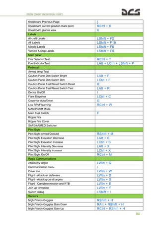
Kneeboard
Kneeboard Next Page ]
Kneeboard ON/OFF RShift + K](https://image.slidesharecdn.com/dcsuh-1hflightmanualen-231006033509-97bc74c0/85/DCS-UH-1H-Flight-Manual_EN-pdf-166-320.jpg)
![DIGITALCOMBATSIMULATORUH-1HHUEY
166
Systems
Chip detectorTAIL ROTOR LWin + B
Chip detector XMSN LAIt + T
Cockpit door open/dose RCtrl + C
Course Indicator OBS Decrease LCtrl + .
Course Indicator OBS Increase LCtrl + ,
Force Trim System On/Off LAIt + U
GMC Manual Heading Decrease LCtrl + LShift + .
GMC Manual Heading Increase LCtrl + LShift + .
GMC Operating Mode Slave/Gyro LAIt + LCtrl + G
GMC Pointer #1ADF/V0R LCtrl + G
GMC Synchronizing + LAIt + LCtrl + ,
GMC Synchronizing o LAIt + LCtrl + .
Hydraulic control On/Off LAIt + 1
Leave Helicopter (3 times) LCtrl + E
Marker Beacon Sensitivity High/Low LShift + V
Marker Beacon Volume Decrease LShift + .
Marker Beacon Volume Increase LShift + ;
UHF Radio Control panel
UHF Preset Channel Decrease LCtrl + LShift + A
UHF Preset Channel Increase LCtrl + LShift + S
UHF Radio 10MHz Decrease LCtrl + LShift + W
UHF Radio 10MHz Increase LCtrl + LShift + E
UHF Radio 1MHz Decrease LCtrl + LShift + R
UHF Radio 1MHz Increase LCtrl + LShift + T
UHF Radio 50kHz Decrease LCtrl + LShift + Y
UHF Radio 50kHz Increase LCtrl + LShift + U
UHF Radio Freq. Mode GD XMIT LCtrl + LShift + 8
UHF Radio Freq. Mode MAN LCtrl + LShift + 7
UHF Radio Freq. Mode PRESET LCtrl + LShift + 6
UHF Radio Freq. Mode Select(rotary) LCtrl + LShift + 5
UHF Radio Mode ADF LCtrl + LShift + 4
UHF Radio Mode OFF LCtrl + LShift + 1
UHF Radio Mode Select(rotary) LCtrl + LShift + '
UHF Radio ModeT/R LCtrl + LShift + 2
UHF Radio ModeT/R+G LCtrl + LShift + 3
UHF Radio Squelch On/Off LCtrl + LShift + Q
UHF Radio Volume Decrease LCtrl + LShift + ;
UHF Radio Volume Increase LCtrl + LShift + '
VHF AM Radio Control panel
VHF AM Radio Freq. MHz Decrease LCtrl + LShift + 0
VHF AM Radio Freq. MHz Increase LCtrl + LShift + P
VHF AM Radio Freq. kHz Decrease LCtrl + LShift + [
VHF AM Radio Freq. kHz Increase LCtrl + LShift + ]](https://image.slidesharecdn.com/dcsuh-1hflightmanualen-231006033509-97bc74c0/85/DCS-UH-1H-Flight-Manual_EN-pdf-168-320.jpg)
![DIGITALCOMBATSIMULATORUH-1HHUEY
167
VHF AM Radio Power ON/OFF LCtrl + LShift + 9
VHF AM Radio Test LCtrl + LShift + I
VHF AM Radio Volume Decrease LCtrl + LShift + -
VHF AM Radio Volume Increase LCtrl + LShift + =
VHF FM Radio Control panel
VHF FM Radio 100kHz Decrease RAIt + RCtrl + T
VHF FM Radio 100kHz Increase RAIt + RCtrl + Y
VHF FM Radio 10MHz Decrease RAIt + RCtrl + 0
VHF FM Radio 10MHz Increase RAIt + RCtrl + W
VHF FM Radio 1MHz Decrease RAIt + RCtrl + E
VHF FM Radio 1MHz Increase RAIt + RCtrl + R
VHF FM Radio 50kHz Decrease RAIt + RCtrl + U
VHF FM Radio 50kHz Increase RAIt + RCtrl + I
VHF FM Radio Mode HOME RAIt + RCtrl + 4
VHF FM Radio Mode OFF RAIt + RCtrl + 1
VHF FM Radio Mode RETRAN RAIt + RCtrl + 3
VHF FM Radio Mode Select (rotary) RAIt + RCtrl + '
VHF FM Radio ModeTR RAIt + RCtrl + 2
VHF FM Radio Squelch CARR RAIt + RCtrl + 7
VHF FM Radio Squelch DIS RAIt + RCtrl + 6
VHF FM Radio Squelch Select (rotary) RAIt + RCtrl + 5
VHF FM Radio Squelch TONE RAIt + RCtrl + 8
VHF FM Radio Volume Decrease RAIt + RCtrl + -
VHF FM Radio Volume Increase RAIt + RCtrl + =
VOR/ILS Control panel
VOR/ILS Freq. MHz Decrease LAIt + LShift + 0
VOR/ILS Freq. MHz Increase LAIt + LShift + P
VOR/ILS Freq. kHz Decrease LAIt + LShift + [
VOR/ILS Freq. kHz Increase LAIt + LShift + ]
VOR/ILS Mode Select (rotary) LAIt + LShift + '
VOR/ILS Power OFF LAIt + LShift + 1
VOR/ILS Power PWR LAIt + LShift + 2
VOR/ILS Power TEST LAIt + LShift + 3
VOR/ILS Volume Decrease LAIt + LShift + -
VOR/ILS Volume Increase LAIt + LShift + =
View
Camera view keyboard rate fast LShift + ]
Camera view keyboard rate normal LAIt + ]
Camera view keyboard rate slow LCtrl + ]
Camera view mouse rate fast LShift + [
Camera view mouse rate normal LAIt +[
Camera view mouse rate slow LCtrl + [
CenterView Num5
F1 Cockpit view F1
F1 HUD only view switch LAIt + F1
F1 Natural head movement view LCtrl + F1](https://image.slidesharecdn.com/dcsuh-1hflightmanualen-231006033509-97bc74c0/85/DCS-UH-1H-Flight-Manual_EN-pdf-169-320.jpg)