This document provides information on engine control systems, including a system diagram, descriptions of onboard diagnostic systems, troubleshooting procedures, diagnostic priority charts, sensor reference values, wiring diagrams, and diagnostic trouble codes (DTCs) with descriptions and diagnostic procedures. It discusses the engine control module (ECM), sensors, actuators, and other control components. Troubleshooting guidelines are provided for intermittent issues, power supply/ground circuits, and specific DTCs related to the throttle, oxygen sensors, ignition, fuel injection, and other systems. Reference values are given for sensors that can be monitored using diagnostic tools.


![EC-10
[HR]
INDEX FOR DTC
Revision: 2006 January C11
[HR]
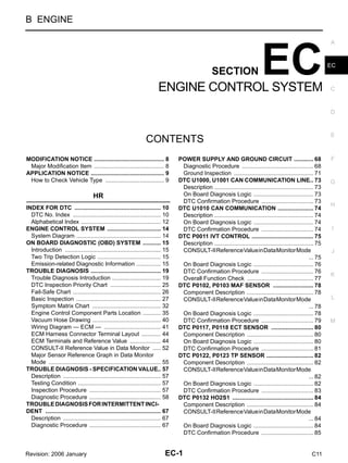
INDEX FOR DTC PFP:00024
DTC No. Index GBS001I0
NOTE:
● If DTC U1000 or U1001 is displayed with other DTC, first perform the trouble diagnosis for DTC
U1000, U1001. Refer to EC-73, "DTC U1000, U1001 CAN COMMUNICATION LINE" .
● If DTC U1010 is displayed with other DTC, first perform the trouble diagnosis for DTC U1010. Refer
to EC-74, "DTC U1010 CAN COMMUNICATION" .
DTC*1
Items
(CONSULT-II screen terms)
Reference page
CONSULT-II ECM*2
U1000 1000*3,
*5 CAN COMM CIRCUIT EC-73
U1001 1001*3 CAN COMM CIRCUIT EC-73
U1010 1010 CONTROL UNIT(CAN) EC-74
P0000 Flashing*4
NO DTC IS DETECTED.
FURTHER TESTING
MAY BE REQUIRED.
—
P0000 0000
NO DTC IS DETECTED.
FURTHER TESTING
MAY BE REQUIRED.
—
P0011 0011 INT/V TIM CONT-B1 EC-75
P0102 0102 MAF SEN/CIRCUIT EC-78
P0103 0103 MAF SEN/CIRCUIT EC-78
P0117 0117 ECT SEN/CIRC EC-80
P0118 0118 ECT SEN/CIRC EC-80
P0122 0122 TP SEN 2/CIRC EC-82
P0123 0123 TP SEN 2/CIRC EC-82
P0132 0132 HO2S1 (B1) EC-84
P0134 0134 HO2S1 (B1) EC-86
P0138 0138 HO2S2 (B1) EC-88
P0222 0222 TP SEN 1/CIRC EC-90
P0223 0223 TP SEN 1/CIRC EC-90
P0327 0327 KNOCK SEN/CIRC-B1 EC-92
P0328 0328 KNOCK SEN/CIRC-B1 EC-92
P0335 0335 CKP SEN/CIRCUIT EC-93
P0340 0340 CMP SEN/CIRC-B1 EC-95
P0605 0605 ECM EC-97
P1065 1065 ECM BACK UP/CIRCUIT EC-99
P1111 1111 INT/V TIM V/CIR-B1 EC-100
P1121 1121 ETC ACTR EC-101
P1122 1122 ETC FUNCTION/CIRC EC-103
P1124 1124 ETC MOT PWR EC-104
P1126 1126 ETC MOT PWR EC-104
P1128 1128 ETC MOT EC-106
P1217 1217 ENG OVER TEMP EC-107
P1225 1225 CTP LEARNING EC-111
P1226 1226 CTP LEARNING EC-112
P1229 1229 SENSOR POWER/CIRC EC-113](https://image.slidesharecdn.com/echr151-231109034013-9a62fb0c/85/ec-hr15-1-pdf-10-320.jpg)
![INDEX FOR DTC
EC-11
[HR]
C
D
E
F
G
H
I
J
K
L
M
A
EC
Revision: 2006 January C11
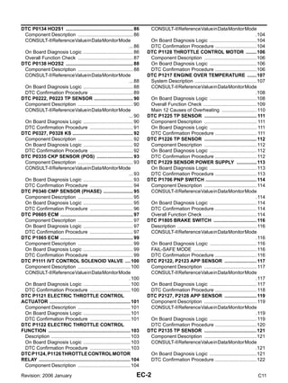
*1: 1st trip DTC No. is the same as DTC No.
*2: In Diagnostic Test Mode II (Self-diagnostic results).
*3: The troubleshooting for this DTC needs CONSULT-II.
*4: When engine is running, MIL may flash.
*5: For A/T models
P1610 - P1615 1610 - 1615 NATS MALFUNCTION BL-42
P1706 1706 P-N POS SW/CIRCUIT EC-114
P1805 1805 BRAKE SW/CIRCUIT EC-116
P2122 2122 APP SEN 1/CIRC EC-117
P2123 2123 APP SEN 1/CIRC EC-117
P2127 2127 APP SEN 2/CIRC EC-119
P2128 2128 APP SEN 2/CIRC EC-119
P2135 2135 TP SENSOR EC-121
P2138 2138 APP SENSOR EC-123
DTC*1
Items
(CONSULT-II screen terms)
Reference page
CONSULT-II ECM*2](https://image.slidesharecdn.com/echr151-231109034013-9a62fb0c/85/ec-hr15-1-pdf-11-320.jpg)
![EC-12
[HR]
INDEX FOR DTC
Revision: 2006 January C11
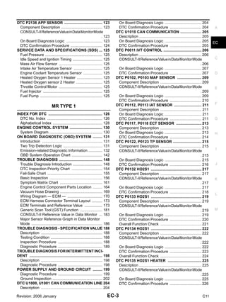
Alphabetical Index GBS001I1
NOTE:
● If DTC U1000 or U1001 is displayed with other DTC, first perform the trouble diagnosis for DTC
U1000, U1001. Refer to EC-73, "DTC U1000, U1001 CAN COMMUNICATION LINE" .
● If DTC U1010 is displayed with other DTC, first perform the trouble diagnosis for DTC U1010. Refer
to EC-74, "DTC U1010 CAN COMMUNICATION" .
Items
(CONSULT-II screen terms)
DTC*1
Reference page
CONSULT-II ECM*2
APP SEN 1/CIRC P2122 2122 EC-117
APP SEN 1/CIRC P2123 2123 EC-117
APP SEN 2/CIRC P2127 2127 EC-119
APP SEN 2/CIRC P2128 2128 EC-119
APP SENSOR P2138 2138 EC-123
BRAKE SW/CIRCUIT P1805 1805 EC-116
CAN COMM CIRCUIT U1000 1000*3, *5 EC-73
CAN COMM CIRCUIT U1001 1001*3 EC-73
CONTROL UNIT(CAN) U1010 1010 EC-74
CKP SEN/CIRCUIT P0335 0335 EC-93
CMP SEN/CIRC-B1 P0340 0340 EC-95
CTP LEARNING P1225 1225 EC-111
CTP LEARNING P1226 1226 EC-112
ECM P0605 0605 EC-97
ECM BACK UP/CIRCUIT P1065 1065 EC-99
ECT SEN/CIRC P0117 0117 EC-80
ECT SEN/CIRC P0118 0118 EC-80
ENG OVER TEMP P1217 1217 EC-107
ETC ACTR P1121 1121 EC-101
ETC FUNCTION/CIRC P1122 1122 EC-103
ETC MOT P1128 1128 EC-106
ETC MOT PWR P1124 1124 EC-104
ETC MOT PWR P1126 1126 EC-104
HO2S1 (B1) P0132 0132 EC-84
HO2S1 (B1) P0134 0134 EC-86
HO2S2 (B1) P0138 0138 EC-88
INT/V TIM CONT-B1 P0011 0011 EC-75
INT/V TIM V/CIR-B1 P1111 1111 EC-100
KNOCK SEN/CIRC-B1 P0327 0327 EC-92
KNOCK SEN/CIRC-B1 P0328 0328 EC-92
MAF SEN/CIRCUIT P0102 0102 EC-78
MAF SEN/CIRCUIT P0103 0103 EC-78
NATS MALFUNCTION P1610 - P1615 1610 - 1615 BL-42
NO DTC IS DETECTED.
FURTHER TESTING
MAY BE REQUIRED.
No DTC Flashing*4 —
NO DTC IS DETECTED.
FURTHER TESTING
MAY BE REQUIRED.
P0000 0000 —](https://image.slidesharecdn.com/echr151-231109034013-9a62fb0c/85/ec-hr15-1-pdf-12-320.jpg)
![INDEX FOR DTC
EC-13
[HR]
C
D
E
F
G
H
I
J
K
L
M
A
EC
Revision: 2006 January C11
*1: 1st trip DTC No. is the same as DTC No.
*2: In Diagnostic Test Mode II (Self-diagnostic results).
*3: The troubleshooting for this DTC needs CONSULT-II.
*4: When engine is running, MIL may flash.
*5: For A/T models
P-N POS SW/CIRCUIT P1706 1706 EC-114
SENSOR POWER/CIRC P1229 1229 EC-113
TP SEN 1/CIRC P0222 0222 EC-90
TP SEN 1/CIRC P0223 0223 EC-90
TP SEN 2/CIRC P0122 0122 EC-82
TP SEN 2/CIRC P0123 0123 EC-82
TP SENSOR P2135 2135 EC-121
Items
(CONSULT-II screen terms)
DTC*1
Reference page
CONSULT-II ECM*2](https://image.slidesharecdn.com/echr151-231109034013-9a62fb0c/85/ec-hr15-1-pdf-13-320.jpg)
![EC-14
[HR]
ENGINE CONTROL SYSTEM
Revision: 2006 January C11
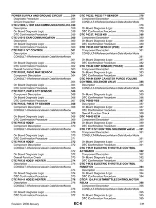
ENGINE CONTROL SYSTEM PFP:23710
System Diagram GBS001I8
PBIB2945E](https://image.slidesharecdn.com/echr151-231109034013-9a62fb0c/85/ec-hr15-1-pdf-14-320.jpg)
![ON BOARD DIAGNOSTIC (OBD) SYSTEM
EC-15
[HR]
C
D
E
F
G
H
I
J
K
L
M
A
EC
Revision: 2006 January C11
ON BOARD DIAGNOSTIC (OBD) SYSTEM PFP:00028
Introduction GBS001IK
The ECM has an on board diagnostic system, which detects malfunctions related to engine sensors or actua-
tors. The ECM also records various emission-related diagnostic information including:
The above information can be checked using procedures listed in the table below.
×: Applicable —: Not applicable
*: When DTC and 1st trip DTC simultaneously appear on the display, they cannot be clearly distinguished from each other.
The malfunction indicator lamp (MIL) on the instrument panel lights up when the same malfunction is detected
in two consecutive trips (Two trip detection logic), or when the ECM enters fail-safe mode. (Refer to EC-26,
"Fail-Safe Chart" .)
Two Trip Detection Logic GBS001IL
When a malfunction is detected for the first time, 1st trip DTC and 1st trip Freeze Frame data are stored in the
ECM memory. The MIL will not light up at this stage. <1st trip>
If the same malfunction is detected again during the next drive, the DTC and Freeze Frame data are stored in
the ECM memory, and the MIL lights up. The MIL lights up at the same time when the DTC is stored. <2nd
trip> The “trip” in the “Two Trip Detection Logic” means a driving mode in which self-diagnosis is performed
during vehicle operation.
When there is an open circuit on MIL circuit, the ECM cannot warn the driver by lighting up MIL when there is
malfunction on engine control system.
Therefore, when electrical controlled throttle and part of ECM related diagnoses are continuously detected as
NG for 5 trips, ECM warns the driver that engine control system malfunctions and MIL circuit is open by means
of operating fail-safe function.
The fail-safe function also operates when above diagnoses except MIL circuit are detected and demands the
driver to repair the malfunction.
Emission-related Diagnostic Information GBS001IM
EMISSION-RELATED DIAGNOSTIC INFORMATION ITEMS
×:Applicable —: Not applicable
Emission-related diagnostic information
Diagnostic Trouble Code (DTC)
Freeze Frame data
1st Trip Diagnostic Trouble Code (1st Trip DTC)
1st Trip Freeze Frame data
DTC 1st trip DTC Freeze Frame data
1st trip Freeze Frame
data
CONSULT-II × × × ×
ECM × ×* — —
Engine operating condition in fail-safe mode Engine speed will not rise more than 2,500 rpm due to the fuel cut
Items
(CONSULT-II screen terms)
DTC*1
Trip MIL
Reference
page
CONSULT-II ECM*2
CAN COMM CIRCUIT U1000 1000*3, *5 2 — EC-73
CAN COMM CIRCUIT U1001 1001*3 2 — EC-73
CONTROL UNIT(CAN) U1010 1010 2 — EC-74
NO DTC IS DETECTED.
FURTHER TESTING
MAY BE REQUIRED.
P0000 0000 — Flashing*4 —
INT/V TIM CONT-B1 P0011 0011 2 — EC-75
MAF SEN/CIRCUIT P0102 0102 1 × EC-78
MAF SEN/CIRCUIT P0103 0103 1 × EC-78
ECT SEN/CIRC P0117 0117 2 × EC-80](https://image.slidesharecdn.com/echr151-231109034013-9a62fb0c/85/ec-hr15-1-pdf-15-320.jpg)
![EC-16
[HR]
ON BOARD DIAGNOSTIC (OBD) SYSTEM
Revision: 2006 January C11
*1: 1st trip DTC No. is the same as DTC No.
*2: In Diagnostic Test Mode II (Self-diagnostic results), this number is controlled by NISSAN.
*3: The troubleshooting for this DTC needs CONSULT-II.
*4: When engine is running, MIL may flash.
*5: For A/T models
DTC AND 1ST TRIP DTC
The 1st trip DTC (whose number is the same as the DTC number) is displayed for the latest self-diagnostic
result obtained. If the ECM memory was cleared previously, and the 1st trip DTC did not reoccur, the 1st trip
DTC will not be displayed.
If a malfunction is detected during the 1st trip, the 1st trip DTC is stored in the ECM memory. The MIL will not
light up (two trip detection logic). If the same malfunction is not detected in the 2nd trip (meeting the required
driving pattern), the 1st trip DTC is cleared from the ECM memory. If the same malfunction is detected in the
2nd trip, both the 1st trip DTC and DTC are stored in the ECM memory and the MIL lights up. In other words,
ECT SEN/CIRC P0118 0118 2 × EC-80
TP SEN 2/CIRC P0122 0122 1 × EC-82
TP SEN 2/CIRC P0123 0123 1 × EC-82
HO2S1 (B1) P0132 0132 2 × EC-84
HO2S1 (B1) P0134 0134 2 × EC-86
HO2S2 (B1) P0138 0138 2 × EC-88
TP SEN 1/CIRC P0222 0222 1 × EC-90
TP SEN 1/CIRC P0223 0223 1 × EC-90
KNOCK SEN/CIRC-B1 P0327 0327 2 — EC-92
KNOCK SEN/CIRC-B1 P0328 0328 2 — EC-92
CKP SEN/CIRCUIT P0335 0335 2 × EC-93
CMP SEN/CIRC-B1 P0340 0340 2 × EC-95
ECM P0605 0605 1 or 2 × or — EC-97
ECM BACK UP/CIRCUIT P1065 1065 2 × EC-99
INT/V TIM V/CIR-B1 P1111 1111 2 × EC-100
ETC ACTR P1121 1121 1 × EC-101
ETC FUNCTION/CIRC P1122 1122 1 × EC-103
ETC MOT PWR P1124 1124 1 × EC-104
ETC MOT PWR P1126 1126 1 × EC-104
ETC MOT P1128 1128 1 × EC-106
ENG OVER TEMP P1217 1217 1 × EC-107
CTP LEARNING P1225 1225 2 — EC-111
CTP LEARNING P1226 1226 2 — EC-112
SENSOR POWER/CIRC P1229 1229 1 × EC-113
NATS MALFUNCTION P1610 - P1615 1610 - 1615 2 — BL-42
P-N POS SW/CIRCUIT P1706 1706 2 × EC-114
BRAKE SW/CIRCUIT P1805 1805 1 × EC-116
APP SEN 1/CIRC P2122 2122 1 × EC-117
APP SEN 1/CIRC P2123 2123 1 × EC-117
APP SEN 2/CIRC P2127 2127 1 × EC-119
APP SEN 2/CIRC P2128 2128 1 × EC-119
TP SENSOR P2135 2135 1 × EC-121
APP SENSOR P2138 2138 1 × EC-123
Items
(CONSULT-II screen terms)
DTC*1
Trip MIL
Reference
page
CONSULT-II ECM*2](https://image.slidesharecdn.com/echr151-231109034013-9a62fb0c/85/ec-hr15-1-pdf-16-320.jpg)
![ON BOARD DIAGNOSTIC (OBD) SYSTEM
EC-17
[HR]
C
D
E
F
G
H
I
J
K
L
M
A
EC
Revision: 2006 January C11
the DTC is stored in the ECM memory and the MIL lights up when the same malfunction occurs in two consec-
utive trips. If a 1st trip DTC is stored and a non-diagnostic operation is performed between the 1st and 2nd
trips, only the 1st trip DTC will continue to be stored. For malfunctions that blink or light up the MIL during the
1st trip, the DTC and 1st trip DTC are stored in the ECM memory.
Procedures for clearing the DTC and the 1st trip DTC from the ECM memory are described in EC-17, "HOW
TO ERASE EMISSION-RELATED DIAGNOSTIC INFORMATION" .
When a 1st trip DTC is detected, check, print out or write down and erase (1st trip) DTC and Freeze Frame
data as specified in Work Flow procedure Step 2, refer to EC-20, "WORK FLOW" . Then perform DTC Confir-
mation Procedure or Overall Function Check to try to duplicate the malfunction. If the malfunction is dupli-
cated, the item requires repair.
How to Read DTC and 1st Trip DTC
DTC and 1st trip DTC can be read by the following methods.
With CONSULT-II
CONSULT-II displays the DTC in “SELF-DIAG RESULTS” mode. Examples: P0117, P0340, P1217, etc.
(CONSULT-II also displays the malfunctioning component or system.)
Without CONSULT-II
The number of blinks of the MIL in the Diagnostic Test Mode II (Self-Diagnostic Results) indicates the DTC.
Example: 0117, 0340, 1217, etc.
● 1st trip DTC No. is the same as DTC No.
● Output of a DTC indicates a malfunction. However, the Diagnostic Test Mode II do not indicate
whether the malfunction is still occurring or has occurred in the past and has returned to normal.
CONSULT-II can identify malfunction status as shown below. Therefore, using CONSULT-II (if avail-
able) is recommended.
A sample of CONSULT-II display for DTC and 1st trip DTC is shown below. DTC or 1st trip DTC of a malfunc-
tion is displayed in SELF-DIAGNOSTIC RESULTS mode of CONSULT-II. Time data indicates how many times
the vehicle was driven after the last detection of a DTC.
If the DTC is being detected currently, the time data will be [0].
If a 1st trip DTC is stored in the ECM, the time data will be [1t].
FREEZE FRAME DATA AND 1ST TRIP FREEZE FRAME DATA
The ECM records the driving conditions such as fuel system status, calculated load value, engine coolant tem-
perature, short term fuel trim, long term fuel trim, engine speed, vehicle speed, base fuel schedule and intake
air temperature at the moment a malfunction is detected.
Data which are stored in the ECM memory, along with the 1st trip DTC, are called 1st trip freeze frame data.
The data, stored together with the DTC data, are called freeze frame data and displayed on CONSULT-II.
Only one set of freeze frame data (either 1st trip freeze frame data or freeze frame data) can be stored in the
ECM. 1st trip freeze frame data is stored in the ECM memory along with the 1st trip DTC. There is no priority
for 1st trip freeze frame data and it is updated each time a different 1st trip DTC is detected. However, once
freeze frame data (2nd trip detection/MIL ON) is stored in the ECM memory, 1st trip freeze frame data is no
longer stored. Remember, only one set of freeze frame data can be stored in the ECM.
Both 1st trip freeze frame data and freeze frame data (along with the DTCs) are cleared when the ECM mem-
ory is erased. Procedures for clearing the ECM memory are described in EC-17, "HOW TO ERASE EMIS-
SION-RELATED DIAGNOSTIC INFORMATION" .
HOW TO ERASE EMISSION-RELATED DIAGNOSTIC INFORMATION
How to Erase DTC
WITH CONSULT-II
PBIB0911E](https://image.slidesharecdn.com/echr151-231109034013-9a62fb0c/85/ec-hr15-1-pdf-17-320.jpg)
![EC-18
[HR]
ON BOARD DIAGNOSTIC (OBD) SYSTEM
Revision: 2006 January C11
The emission related diagnostic information in the ECM can be erased by selecting “ERASE” in the “SELF-
DIAG RESULTS” mode with CONSULT-II.
1. If the ignition switch stays ON after repair work, be sure to turn ignition switch OFF once. Wait at least 10
seconds and then turn it ON (engine stopped) again.
2. Touch “ENGINE”.
3. Touch “SELF-DIAG RESULTS”.
4. Touch “ERASE”. (The DTC in the ECM will be erased.)
Without CONSULT-II
1. If the ignition switch stays ON after repair work, be sure to turn ignition switch OFF once.
2. Wait at least 10 seconds and then turn it ON (engine stopped) again.
3. Change the diagnostic test mode from Mode II to Mode I by depressing the accelerator pedal.
● If the battery is disconnected, the emission-related diagnostic information will be lost within 24
hours.
● The following data are cleared when the ECM memory is erased.
– Diagnostic trouble codes
– 1st trip diagnostic trouble codes
– Freeze frame data
– 1st trip freeze frame data
Actual work procedures are explained using a DTC as an example. Be careful so that not only the DTC, but all
of the data listed above, are cleared from the ECM memory during work procedures.
PBIB2454E](https://image.slidesharecdn.com/echr151-231109034013-9a62fb0c/85/ec-hr15-1-pdf-18-320.jpg)
![TROUBLE DIAGNOSIS
EC-19
[HR]
C
D
E
F
G
H
I
J
K
L
M
A
EC
Revision: 2006 January C11
TROUBLE DIAGNOSIS PFP:00004
Trouble Diagnosis Introduction GBS001IU
INTRODUCTION
The engine has an ECM to control major systems such as fuel con-
trol, ignition control, idle air control system, etc. The ECM accepts
input signals from sensors and instantly drives actuators. It is essen-
tial that both input and output signals are proper and stable. At the
same time, it is important that there are no malfunctions such as vac-
uum leaks, fouled spark plugs, or other malfunctions with the engine.
It is much more difficult to diagnose an incident that occurs intermit-
tently rather than continuously. Most intermittent incidents are
caused by poor electric connections or improper wiring. In this case,
careful checking of suspected circuits may help prevent the replace-
ment of good parts.
A visual check only may not find the cause of the incidents. A road
test with CONSULT-II or a circuit tester connected should be per-
formed. Follow the Work Flow on EC-20, "WORK FLOW" .
Before undertaking actual checks, take a few minutes to talk with a
customer who approaches with a driveability complaint. The cus-
tomer can supply good information about such incidents, especially
intermittent ones. Find out what symptoms are present and under
what conditions they occur. A Diagnostic Worksheet like the example
on EC-24, "Worksheet Sample" should be used.
Start your diagnosis by looking for conventional malfunctions first.
This will help troubleshoot driveability malfunctions on an electroni-
cally controlled engine vehicle.
MEF036D
SEF233G
SEF234G](https://image.slidesharecdn.com/echr151-231109034013-9a62fb0c/85/ec-hr15-1-pdf-19-320.jpg)
![EC-20
[HR]
TROUBLE DIAGNOSIS
Revision: 2006 January C11
WORK FLOW
Overall Sequence
PBIB3126E](https://image.slidesharecdn.com/echr151-231109034013-9a62fb0c/85/ec-hr15-1-pdf-20-320.jpg)
![TROUBLE DIAGNOSIS
EC-21
[HR]
C
D
E
F
G
H
I
J
K
L
M
A
EC
Revision: 2006 January C11
Detailed Flow
1. GET INFORMATION FOR SYMPTOM
Get the detailed information from the customer about the symptom (the condition and the environment when
the incident/malfunction occurred) using the EC-23, "DIAGNOSTIC WORKSHEET" .
>> GO TO 2.
2. CHECK DTC*1
1. Check DTC*1
.
2. Perform the following procedure if DTC*1
is displayed.
– Record DTC*1
and freeze frame data*2
. (Print them out with CONSULT-II.)
– Erase DTC*1
. (Refer to EC-17, "HOW TO ERASE EMISSION-RELATED DIAGNOSTIC INFORMATION"
.)
– Study the relationship between the cause detected by DTC*1
and the symptom described by the cus-
tomer. (Symptom Matrix Chart is useful. Refer to EC-32, "Symptom Matrix Chart" .)
3. Check related service bulletins for information.
Is any symptom described and any DTC detected?
Symptom is described, DTC*1
is displayed>>GO TO 3.
Symptom is described, DTC*1
is not displayed>>GO TO 4.
Symptom is not described, DTC*1
is displayed>>GO TO 5.
3. CONFIRM THE SYMPTOM
Try to confirm the symptom described by the customer (except MIL ON).
DIAGNOSIS WORK SHEET is useful to verify the incident.
Connect CONSULT-II to the vehicle in “DATA MONITOR (AUTO TRIG)” mode and check real time diagnosis
results.
Verify relation between the symptom and the condition when the symptom is detected.
>> GO TO 5.
4. CONFIRM THE SYMPTOM
Try to confirm the symptom described by the customer.
DIAGNOSIS WORK SHEET is useful to verify the incident.
Connect CONSULT-II to the vehicle in “DATA MONITOR (AUTO TRIG)” mode and check real time diagnosis
results.
Verify relation between the symptom and the condition when the symptom is detected.
>> GO TO 6.](https://image.slidesharecdn.com/echr151-231109034013-9a62fb0c/85/ec-hr15-1-pdf-21-320.jpg)
![EC-22
[HR]
TROUBLE DIAGNOSIS
Revision: 2006 January C11
5. PERFORM DTC CONFIRMATION PROCEDURE
Perform DTC Confirmation Procedure for the displayed DTC*1
, and then make sure that DTC*1
is detected
again.
At this time, always connect CONSULT-II to the vehicle, and check diagnostic results in real time on “DATA
MONITOR (AUTO TRIG)”.
If two or more DTCs*1
are detected, refer to EC-25, "DTC Inspection Priority Chart" and determine trouble
diagnosis order.
NOTE:
● Freeze frame data*2
is useful if the DTC*1
is not detected.
● Perform Overall Function Check if DTC Confirmation Procedure is not included on Service Manual. This
simplified check procedure is an effective alternative though DTC*1
cannot be detected during this check.
If the result of Overall Function Check is NG, it is the same as the detection of DTC*1
by DTC Confirma-
tion Procedure.
Is DTC*1
detected?
Yes >> GO TO 10.
No >> Check according to EC-67, "TROUBLE DIAGNOSIS FOR INTERMITTENT INCIDENT" .
6. PERFORM BASIC INSPECTION
Perform EC-27, "Basic Inspection" .
With CONSULT-II>>GO TO 7.
Without CONSULT-II>>GO TO 9.
7. PERFORM DATA MONITOR (SPEC) MODE
With CONSULT-II
Make sure that “MAS A/F SE-B1”, “B/FUEL SCHDL”, and “A/F
ALPHA-B1” are within the SP value using CONSULT-II “DATA MON-
ITOR (SPEC)” mode. Refer to EC-57, "Inspection Procedure" .
Are they within the SP value?
Yes >> GO TO 9.
No >> GO TO 8.
8. DETECT MALFUNCTIONING PART BY TROUBLE DIAGNOSIS - SPECIFICATION VALUE
Detect malfunctioning part according to EC-58, "Diagnostic Procedure" .
Is malfunctioning part detected?
Yes >> GO TO 11.
No >> GO TO 9.
9. DETECT MALFUNCTIONING SYSTEM BY SYMPTOM MATRIX CHART
Detect malfunctioning system according to EC-32, "Symptom Matrix Chart" based on the confirmed symptom
in step 4, and determine the trouble diagnosis order based on possible causes and symptom.
>> GO TO 10.
SEF601Z](https://image.slidesharecdn.com/echr151-231109034013-9a62fb0c/85/ec-hr15-1-pdf-22-320.jpg)
![TROUBLE DIAGNOSIS
EC-23
[HR]
C
D
E
F
G
H
I
J
K
L
M
A
EC
Revision: 2006 January C11
10. DETECT MALFUNCTIONING PART
Inspect the system.
Is malfunctioning part detected?
Yes >> GO TO 11.
No >> Monitor input data from related sensors or check voltage of related ECM terminals using CON-
SULT-II. Refer to EC-44, "ECM Terminals and Reference Value" , EC-52, "CONSULT-II Reference
Value in Data Monitor" .
11. REPAIR OR REPLACE THE MALFUNCTIONING PART
1. Repair or replace the malfunctioning part.
2. Reconnect parts or connectors after repair and replacement.
3. Check DTC. If DTC is displayed, erase it, refer to EC-17, "HOW TO ERASE EMISSION-RELATED DIAG-
NOSTIC INFORMATION" .
>> GO TO 12.
12. FINAL CHECK
When DTC was detected in step 2, perform DTC Confirmation Procedure or Overall Function Check again,
and then make sure that the malfunction have been repaired securely.
When symptom was described from the customer, refer to confirmed symptom in step 3 or 4, and make sure
that the symptom is not detected.
OK or NG
NG (DTC*1
is detected)>>GO TO 10.
NG (Symptom remains)>>GO TO 6.
OK >> 1. Before returning the vehicle to the customer, make sure to erase unnecessary DTC*1
in ECM.
(Refer to EC-17, "HOW TO ERASE EMISSION-RELATED DIAGNOSTIC INFORMATION" .)
2. INSPECTION END
*1: Include 1st trip DTC.
*2: Include 1st trip freeze frame data.
DIAGNOSTIC WORKSHEET
Description
There are many operating conditions that lead to the malfunction of
engine components. A good grasp of such conditions can make trou-
bleshooting faster and more accurate.
In general, each customer feels differently about a incident. It is
important to fully understand the symptoms or conditions for a cus-
tomer complaint.
Utilize a diagnostic worksheet like the one on the next page in order
to organize all the information for troubleshooting.
SEF907L](https://image.slidesharecdn.com/echr151-231109034013-9a62fb0c/85/ec-hr15-1-pdf-23-320.jpg)
![EC-24
[HR]
TROUBLE DIAGNOSIS
Revision: 2006 January C11
Worksheet Sample
MTBL0017](https://image.slidesharecdn.com/echr151-231109034013-9a62fb0c/85/ec-hr15-1-pdf-24-320.jpg)
![TROUBLE DIAGNOSIS
EC-25
[HR]
C
D
E
F
G
H
I
J
K
L
M
A
EC
Revision: 2006 January C11
DTC Inspection Priority Chart GBS001IV
If some DTCs are displayed at the same time, perform inspections one by one based on the following priority
chart.
NOTE:
● If DTC U1000 or U1001 is displayed with other DTC, first perform the trouble diagnosis for DTC
U1000, U1001. Refer to EC-73, "DTC U1000, U1001 CAN COMMUNICATION LINE" .
● If DTC U1010 is displayed with other DTC, first perform the trouble diagnosis for DTC U1010. Refer
to EC-74, "DTC U1010 CAN COMMUNICATION" .
Priority Detected items (DTC)
1 ● U1000 U1001 CAN communication line
● U1010 CAN communication
● P0102 P0103 Mass air flow sensor
● P0117 P0118 Engine coolant temperature sensor
● P0122 P0123 P0222 P0223 P1225 P1226 P2135 Throttle position sensor
● P0327 P0328 Knock sensor
● P0335 Crankshaft position sensor (POS)
● P0340 Camshaft position sensor (PHASE)
● P0605 ECM
● P1229 Sensor power supply
● P1610 - P1615 NATS
● P1706 Park/Neutral position (PNP) switch
● P2122 P2123 P2127 P2128 P2138 Accelerator pedal position sensor
2 ● P0132 P0134 Heated oxygen sensor 1
● P0138 Heated oxygen sensor 2
● P1065 ECM
● P1111 Intake valve timing control solenoid valve
● P1122 Electric throttle control function
● P1124 P1126 Throttle control motor relay
● P1128 Throttle control motor
● P1217 Engine over temperature (OVERHEAT)
● P1805 Brake switch
3 ● P0011 Intake valve timing control
● P1121 Electric throttle control actuator](https://image.slidesharecdn.com/echr151-231109034013-9a62fb0c/85/ec-hr15-1-pdf-25-320.jpg)
![EC-26
[HR]
TROUBLE DIAGNOSIS
Revision: 2006 January C11
Fail-Safe Chart GBS001IW
When the DTC listed below is detected, the ECM enters fail-safe mode and the MIL lights up.
● When there is an open circuit on MIL circuit, the ECM cannot warn the driver by lighting up MIL when
there is malfunction on engine control system.
Therefore, when electrical controlled throttle and part of ECM related diagnoses are continuously detected
as NG for 5 trips, ECM warns the driver that engine control system malfunctions and MIL circuit is open by
means of operating fail-safe function.
The fail-safe function also operates when above diagnoses except MIL circuit are detected and demands
the driver to repair the malfunction.
DTC No. Detected items Engine operating condition in fail-safe mode
P0102
P0103
Mass air flow sensor circuit Engine speed will not rise more than 2,400 rpm due to the fuel cut.
P0122
P0123
P0222
P0223
P2135
Throttle position sensor The ECM controls the electric throttle control actuator in regulating the throttle opening
in order for the idle position to be within +10 degrees.
The ECM regulates the opening speed of the throttle valve to be slower than the nor-
mal condition.
So, the acceleration will be poor.
P1121 Electric throttle control actu-
ator
(When electric throttle control actuator does not function properly due to the return
spring malfunction:)
ECM controls the electric throttle actuator by regulating the throttle opening around the
idle position. The engine speed will not rise more than 2,000 rpm.
(When throttle valve opening angle in fail-safe mode is not in specified range:)
ECM controls the electric throttle control actuator by regulating the throttle opening to
20 degrees or less.
(When ECM detects the throttle valve is stuck open:)
While the vehicle is driving, it slows down gradually by fuel cut. After the vehicle stops,
the engine stalls.
The engine can restart in N or P (A/T), Neutral (M/T) position, and engine speed will
not exceed 1,000 rpm or more.
P1122 Electric throttle control func-
tion
ECM stops the electric throttle control actuator control, throttle valve is maintained at a
fixed opening (approx. 5 degrees) by the return spring.
P1124
P1126
Throttle control relay ECM stops the electric throttle control actuator control, throttle valve is maintained at a
fixed opening (approx. 5 degrees) by the return spring.
P1128 Throttle control motor ECM stops the electric throttle control actuator control, throttle valve is maintained at a
fixed opening (approx. 5 degrees) by the return spring.
P1229 Sensor power supply ECM stops the electric throttle control actuator control, throttle valve is maintained at a
fixed opening (approx. 5 degrees) by the return spring.
P1805 Brake switch ECM controls the electric throttle control actuator by regulating the throttle opening to a
small range.
Therefore, acceleration will be poor.
Vehicle condition Driving condition
When engine is idling Normal
When accelerating Poor acceleration
P2122
P2123
P2127
P2128
P2138
Accelerator pedal position
sensor
The ECM controls the electric throttle control actuator in regulating the throttle opening
in order for the idle position to be within +10 degrees.
The ECM regulates the opening speed of the throttle valve to be slower than the nor-
mal condition.
So, the acceleration will be poor.
Engine operating condition in fail-safe mode Engine speed will not rise more than 2,500 rpm due to the fuel cut](https://image.slidesharecdn.com/echr151-231109034013-9a62fb0c/85/ec-hr15-1-pdf-26-320.jpg)
![TROUBLE DIAGNOSIS
EC-27
[HR]
C
D
E
F
G
H
I
J
K
L
M
A
EC
Revision: 2006 January C11
Basic Inspection GBS001IO
1. INSPECTION START
1. Check service records for any recent repairs that may indicate a related malfunction, or a current need for
scheduled maintenance.
2. Open engine hood and check the following:
– Harness connectors for improper connections
– Wiring harness for improper connections, pinches and cut
– Vacuum hoses for splits, kinks and improper connections
– Hoses and ducts for leaks
– Air cleaner clogging
– Gasket
3. Confirm that electrical or mechanical loads are not applied.
– Headlamp switch is OFF.
– Air conditioner switch is OFF.
– Rear window defogger switch is OFF.
– Steering wheel is in the straight-ahead position, etc.
4. Start engine and warm it up until engine coolant temperature
indicator points the middle of gauge.
Ensure engine stays below 1,000 rpm.
5. Run engine at about 2,000 rpm for about 2 minutes under no
load.
6. Make sure that no DTC is displayed with CONSULT-II.
OK or NG
OK >> GO TO 3.
NG >> GO TO 2.
2. REPAIR OR REPLACE
Repair or replace components as necessary.
>> GO TO 3
SEF983U
SEF976U
SEF977U](https://image.slidesharecdn.com/echr151-231109034013-9a62fb0c/85/ec-hr15-1-pdf-27-320.jpg)
![EC-28
[HR]
TROUBLE DIAGNOSIS
Revision: 2006 January C11
3. CHECK TARGET IDLE SPEED
With CONSULT-II
1. Run engine at about 2,000 rpm for about 2 minutes under no load.
2. Rev engine (2,000 to 3,000 rpm) two or three times under no
load, then run engine at idle speed for about 1 minute.
3. Read idle speed in “DATA MONITOR” mode with CONSULT-II.
Without CONSULT-II
1. Run engine at about 2,000 rpm for about 2 minutes under no load.
2. Rev engine (2,000 to 3,000 rpm) two or three times under no load, then run engine at idle speed for about
1 minute.
3. Check idle speed.
OK or NG
OK >> GO TO 10.
NG >> GO TO 4.
4. PERFORM ACCELERATOR PEDAL RELEASED POSITION LEARNING
1. Stop engine.
2. Perform Accelerator Pedal Released Position Learning.
>> GO TO 5.
5. PERFORM THROTTLE VALVE CLOSED POSITION LEARNING
Perform Throttle Valve Closed Position Learning.
>> GO TO 6.
PBIA8513J
A/T: 700 ± 50 rpm (in P or N position)
M/T: 650 ± 50 rpm (in Neutral position)
SEF058Y
A/T: 700 ± 50 rpm (in P or N position)
M/T: 650 ± 50 rpm (in Neutral position)](https://image.slidesharecdn.com/echr151-231109034013-9a62fb0c/85/ec-hr15-1-pdf-28-320.jpg)
![TROUBLE DIAGNOSIS
EC-29
[HR]
C
D
E
F
G
H
I
J
K
L
M
A
EC
Revision: 2006 January C11
6. PERFORM IDLE AIR VOLUME LEARNING
Perform Idel Air Volume Learning.
Is Idle Air Volume Learning carried out successfully?
Yes or No
Yes >> GO TO 7.
No >> 1. Follow the instruction of Idle Air Volume Learning.
2. GO TO 4.
7. CHECK TARGET IDLE SPEED AGAIN
With CONSULT-II
1. Start engine and warm it up to normal operating temperature.
2. Read idle speed in “DATA MONITOR” mode with CONSULT-II.
Without CONSULT-II
1. Start engine and warm it up to normal operating temperature.
2. Check idle speed.
OK or NG
OK >> GO TO 10.
NG >> GO TO 8.
8. DETECT MALFUNCTIONING PART
Check the Following.
● Check camshaft position sensor (PHASE) and circuit. Refer to EC-95, "DTC P0340 CMP SENSOR
(PHASE)" .
● Check crankshaft position sensor (POS) and circuit. Refer to EC-93, "DTC P0335 CKP SENSOR (POS)" .
OK or NG
OK >> GO TO 9.
NG >> 1. Repair or replace.
2. GO TO 4.
9. CHECK ECM FUNCTION
1. Substitute another known-good ECM to check ECM function. (ECM may be the cause of an incident, but
this is a rare case.)
2. Perform initialization of NATS system and registration of all NATS ignition key IDs. Refer to BL-42, "ECM
Re-communicating Function" .
>> GO TO 4.
A/T: 700 ± 50 rpm (in P or N position)
M/T: 650 ± 50 rpm (in Neutral position)
A/T: 700 ± 50 rpm (in P or N position)
M/T: 650 ± 50 rpm (in Neutral position) SEF174Y](https://image.slidesharecdn.com/echr151-231109034013-9a62fb0c/85/ec-hr15-1-pdf-29-320.jpg)
![EC-30
[HR]
TROUBLE DIAGNOSIS
Revision: 2006 January C11
10. CHECK IGNITION TIMING
1. Run engine at idle.
2. Check ignition timing with a timing light.
– Timing indicator (1)
OK or NG
OK >> INSPECTION END
NG >> GO TO 11.
11. PERFORM ACCELERATOR PEDAL RELEASED POSITION LEARNING
1. Stop engine.
2. Perform Accelerator Pedal Released Position Learning.
>> GO TO 12.
12. PERFORM THROTTLE VALVE CLOSED POSITION LEARNING
Perform Throttle Valve Closed Position Learning.
>> GO TO 13.
13. PERFORM IDLE AIR VOLUME LEARNING
Perform Idel Air Volume Learning.
Is Idle Air Volume Learning carried out successfully?
Yes or No
Yes >> GO TO 14.
No >> 1. Follow the instruction of Idle Air Volume Learning.
2. GO TO 4.
14. CHECK TARGET IDLE SPEED AGAIN
With CONSULT-II
1. Start engine and warm it up to normal operating temperature.
2. Read idle speed in “DATA MONITOR” mode with CONSULT-II.
Without CONSULT-II
1. Start engine and warm it up to normal operating temperature.
2. Check idle speed.
OK or NG
OK >> GO TO 15.
NG >> GO TO 17.
A/T: 6 ± 5° BTDC (in P or N position)
M/T: 6 ± 5° BTDC (in Neutral position)
PBIB2954E
A/T: 700 ± 50 rpm (in P or N position)
M/T: 650 ± 50 rpm (in Neutral position)
A/T: 700 ± 50 rpm (in P or N position)
M/T: 650 ± 50 rpm (in Neutral position) SEF174Y](https://image.slidesharecdn.com/echr151-231109034013-9a62fb0c/85/ec-hr15-1-pdf-30-320.jpg)
![TROUBLE DIAGNOSIS
EC-31
[HR]
C
D
E
F
G
H
I
J
K
L
M
A
EC
Revision: 2006 January C11
15. CHECK IGNITION TIMING AGAIN
1. Run engine at idle.
2. Check ignition timing with a timing light.
– Timing indicator (1)
OK or NG
OK >> INSPECTION END
NG >> GO TO 16.
16. CHECK TIMING CHAIN INSTALLATION
Check timing chain installation. Refer to EM-18, "TIMING CHAIN" .
OK or NG
OK >> GO TO 17.
NG >> 1. Repair the timing chain installation.
2. GO TO 4.
17. DETECT MALFUNCTIONING PART
Check the following.
● Check camshaft position sensor (PHASE) and circuit. Refer to EC-95, "DTC P0340 CMP SENSOR
(PHASE)" .
● Check crankshaft position sensor (POS) and circuit. Refer to EC-93, "DTC P0335 CKP SENSOR (POS)" .
OK or NG
OK >> GO TO 18.
NG >> 1. Repair or replace.
2. GO TO 4.
18. CHECK ECM FUNCTION
1. Substitute another known-good ECM to check ECM function. (ECM may be the cause of an incident, but
this is a rare case.)
2. Perform initialization of NATS system and registration of all NATS ignition key IDs. Refer to BL-42, "ECM
Re-communicating Function" .
>> GO TO 4.
A/T: 6 ± 5° BTDC (in P or N position)
M/T: 6 ± 5° BTDC (in Neutral position)
PBIB2954E](https://image.slidesharecdn.com/echr151-231109034013-9a62fb0c/85/ec-hr15-1-pdf-31-320.jpg)
![EC-32
[HR]
TROUBLE DIAGNOSIS
Revision: 2006 January C11
Symptom Matrix Chart GBS001IX
SYSTEM — BASIC ENGINE CONTROL SYSTEM
1 - 6: The numbers refer to the order of inspection.
(continued on next page)
SYMPTOM
HARD/NO
START/RESTART
(EXCP.
HA)
ENGINE
STALL
HESITATION/SURGING/FLAT
SPOT
SPARK
KNOCK/DETONATION
LACK
OF
POWER/POOR
ACCELERATION
HIGH
IDLE/LOW
IDLE
ROUGH
IDLE/HUNTING
IDLING
VIBRATION
SLOW/NO
RETURN
TO
IDLE
OVERHEATS/WATER
TEMPERATURE
HIGH
EXCESSIVE
FUEL
CONSUMPTION
EXCESSIVE
OIL
CONSUMPTION
BATTERY
DEAD
(UNDER
CHARGE)
Warranty symptom code AA AB AC AD AE AF AG AH AJ AK AL AM HA
Fuel Fuel pump circuit 1 1 2 3 2 2 2 3 2
Fuel pressure regulator system 3 3 4 4 4 4 4 4 4 4
Fuel injector circuit 1 1 2 3 2 2 2 2
Evaporative emission system 3 3 4 4 4 4 4 4 4 4
Air Positive crankcase ventilation system
3 3
4 4 4 4 4 4 4 4 1
Incorrect idle speed adjustment 1 1 1 1 1
Electric throttle control actuator 1 1 2 3 3 2 2 2 2 2 2
Ignition Incorrect ignition timing adjustment 3 3 1 1 1 1 1 1
Ignition circuit 1 1 2 2 2 2 2 2
Main power supply and ground circuit 2 2 3 3 3 3 3 2 3
Mass air flow sensor circuit
1
1 2
2
2 2 2 2
Engine coolant temperature sensor circuit
3
3 3
Heated oxygen sensor 1 circuit
Throttle position sensor circuit
2 2
Accelerator pedal position sensor circuit 3 2 1
Knock sensor circuit 2 3
Crankshaft position sensor (POS) circuit 2 2
Camshaft position sensor (PHASE) circuit 3 2
Vehicle speed signal circuit 2 3 3 3
ECM 2 2 3 3 3 3 3 3 3 3 3
Intake valve timing control solenoid valve circuit 3 2 1 3 2 2 3 3
PNP switch circuit 3 3 3 3 3
Refrigerant pressure sensor circuit 2 3 3 4
Electrical load signal circuit 3
Air conditioner circuit 2 2 3 3 3 3 3 3 3 3 2
ABS actuator and electric unit (control unit) 4](https://image.slidesharecdn.com/echr151-231109034013-9a62fb0c/85/ec-hr15-1-pdf-32-320.jpg)
![TROUBLE DIAGNOSIS
EC-33
[HR]
C
D
E
F
G
H
I
J
K
L
M
A
EC
Revision: 2006 January C11
SYSTEM — ENGINE MECHANICAL & OTHER
SYMPTOM
HARD/NO
START/RESTART
(EXCP.
HA)
ENGINE
STALL
HESITATION/SURGING/FLAT
SPOT
SPARK
KNOCK/DETONATION
LACK
OF
POWER/POOR
ACCELERATION
HIGH
IDLE/LOW
IDLE
ROUGH
IDLE/HUNTING
IDLING
VIBRATION
SLOW/NO
RETURN
TO
IDLE
OVERHEATS/WATER
TEMPERATURE
HIGH
EXCESSIVE
FUEL
CONSUMPTION
EXCESSIVE
OIL
CONSUMPTION
BATTERY
DEAD
(UNDER
CHARGE)
Warranty symptom code AA AB AC AD AE AF AG AH AJ AK AL AM HA
Fuel Fuel tank
5
5
Fuel piping 5 5 5 5 5 5
Vapor lock
Valve deposit
5 5 5 5 5 5 5
Poor fuel (Heavy weight gasoline, Low
octane)
Air Air duct
5 5 5 5 5 5
Air cleaner
Air leakage from air duct
(Mass air flow sensor — electric throttle
control actuator)
5 5 5 5
Electric throttle control actuator
Air leakage from intake manifold/Collector/
Gasket
Cranking Battery
1 1 1 1 1 1
1
1
Generator circuit
Starter circuit 3
Signal plate 6
PNP switch 4
Engine Cylinder head
5 5 5 5 5 5 5 5
Cylinder head gasket 4 3
Cylinder block
6 6 6 6 6 6 6 6
4
Piston
Piston ring
Connecting rod
Bearing
Crankshaft
Valve mecha-
nism
Timing chain
5 5 5 5 5 5 5 5
Camshaft
Intake valve timing control
Intake valve
3
Exhaust valve](https://image.slidesharecdn.com/echr151-231109034013-9a62fb0c/85/ec-hr15-1-pdf-33-320.jpg)
![EC-34
[HR]
TROUBLE DIAGNOSIS
Revision: 2006 January C11
1 - 6: The numbers refer to the order of inspection.
Exhaust Exhaust manifold/Tube/Muffler/Gasket
5 5 5 5 5 5 5 5
Three way catalyst
Lubrication Oil pan/Oil strainer/Oil pump/Oil filter/Oil
gallery 5 5 5 5 5 5 5 5
Oil level (Low)/Filthy oil
Cooling Radiator/Hose/Radiator filler cap
5 5 5 5 5 5 5 4 5
Thermostat 5
Water pump
Water gallery
Cooling fan
5
Coolant level (Low)/Contaminated coolant
NATS (Nissan Anti-Theft System) 1 1
SYMPTOM
HARD/NO
START/RESTART
(EXCP.
HA)
ENGINE
STALL
HESITATION/SURGING/FLAT
SPOT
SPARK
KNOCK/DETONATION
LACK
OF
POWER/POOR
ACCELERATION
HIGH
IDLE/LOW
IDLE
ROUGH
IDLE/HUNTING
IDLING
VIBRATION
SLOW/NO
RETURN
TO
IDLE
OVERHEATS/WATER
TEMPERATURE
HIGH
EXCESSIVE
FUEL
CONSUMPTION
EXCESSIVE
OIL
CONSUMPTION
BATTERY
DEAD
(UNDER
CHARGE)
Warranty symptom code AA AB AC AD AE AF AG AH AJ AK AL AM HA](https://image.slidesharecdn.com/echr151-231109034013-9a62fb0c/85/ec-hr15-1-pdf-34-320.jpg)
![TROUBLE DIAGNOSIS
EC-35
[HR]
C
D
E
F
G
H
I
J
K
L
M
A
EC
Revision: 2006 January C11
Engine Control Component Parts Location GBS001IY
1. Ignition coil (with power transistor)
and spark plug
2. Intake valve timing control solenoid
valve
3. Refrigerant pressure sensor
4. Knock sensor 5. Fuel injector 6. Cooling fan motor
7. Camshaft position sensor (PHASE) 8. IPDM E/R 9. ECM
10. Mass air flow sensor
(with intake air temperature sensor)
11. Engine coolant temperature sensor 12. Electric throttle control actuator
(with built-in throttle position sensor,
throttle control motor)
13. EVAP canister purge volume control
solenoid valve
PBIB2939E](https://image.slidesharecdn.com/echr151-231109034013-9a62fb0c/85/ec-hr15-1-pdf-35-320.jpg)
![EC-36
[HR]
TROUBLE DIAGNOSIS
Revision: 2006 January C11
: Vehicle front
1. Mass air flow sensor
(with intake air temperature sensor)
2. Engine coolant temperature sensor 3. Electric throttle control actuator
4. Camshaft position sensor (PHASE) 5. Ignition coil (with power transistor) 6. Fuel injector
7. EVAP canister purge volume control
solenoid valve
PBIB2940E](https://image.slidesharecdn.com/echr151-231109034013-9a62fb0c/85/ec-hr15-1-pdf-36-320.jpg)
![TROUBLE DIAGNOSIS
EC-37
[HR]
C
D
E
F
G
H
I
J
K
L
M
A
EC
Revision: 2006 January C11
: Vehicle front
1. ECM harness connectors 2. ECM 3. IPDM E/R
4. Fuel pump fuse (15A) 5. Intake valve timing control solenoid
valve
6. Knock sensor
7. Refrigerant pressure sensor 8. PCV valve
PBIB2941E](https://image.slidesharecdn.com/echr151-231109034013-9a62fb0c/85/ec-hr15-1-pdf-37-320.jpg)
![EC-38
[HR]
TROUBLE DIAGNOSIS
Revision: 2006 January C11
PBIB2942E
: Vehicle front
1. Exhaust manifold 2. Heated oxygen sensor 1 3. Heated oxygen sensor 2
4. Heated oxygen sensor 2 harness
connector
PBIB2943E](https://image.slidesharecdn.com/echr151-231109034013-9a62fb0c/85/ec-hr15-1-pdf-38-320.jpg)
![TROUBLE DIAGNOSIS
EC-39
[HR]
C
D
E
F
G
H
I
J
K
L
M
A
EC
Revision: 2006 January C11
1. Cooling fan motor 2. Crankshaft position sensor (POS) 3. Stop lamp switch
4. Brake pedal 5. Accelerator pedal position sensor
harness connector
6. Accelerator pedal position sensor
7. Accelerator pedal 8. Fuel level sensor unit and fuel pump
harness connector
9. Fuel pressure regulator
10. Fuel pump
PBIB2944E](https://image.slidesharecdn.com/echr151-231109034013-9a62fb0c/85/ec-hr15-1-pdf-39-320.jpg)
![EC-40
[HR]
TROUBLE DIAGNOSIS
Revision: 2006 January C11
Vacuum Hose Drawing GBS001IZ
Refer to EC-14, "System Diagram" for Vacuum Control System.
: Vehicle front : To EVAP canister
1. Intake manifold 2. EVAP canister purge volume control
solenoid valve
3. EVAP purge resonator
NOTE:
Do not use soapy water or any type of solvent while installing vacuum hoses or purge hoses.
PBIB2946E](https://image.slidesharecdn.com/echr151-231109034013-9a62fb0c/85/ec-hr15-1-pdf-40-320.jpg)
![TROUBLE DIAGNOSIS
EC-41
[HR]
C
D
E
F
G
H
I
J
K
L
M
A
EC
Revision: 2006 January C11
Wiring Diagram — ECM — GBS001J0
TBWB1171E](https://image.slidesharecdn.com/echr151-231109034013-9a62fb0c/85/ec-hr15-1-pdf-41-320.jpg)
![EC-42
[HR]
TROUBLE DIAGNOSIS
Revision: 2006 January C11
TBWB0984E](https://image.slidesharecdn.com/echr151-231109034013-9a62fb0c/85/ec-hr15-1-pdf-42-320.jpg)
![TROUBLE DIAGNOSIS
EC-43
[HR]
C
D
E
F
G
H
I
J
K
L
M
A
EC
Revision: 2006 January C11
TBWB0985E](https://image.slidesharecdn.com/echr151-231109034013-9a62fb0c/85/ec-hr15-1-pdf-43-320.jpg)
![EC-44
[HR]
TROUBLE DIAGNOSIS
Revision: 2006 January C11
ECM Harness Connector Terminal Layout GBS001J1
ECM Terminals and Reference Value GBS001J2
PREPARATION
1. ECM (1) is located in the engine room left side near battery.
● : Vehicle front
2. Disconnect ECM harness connector.
● When disconnecting ECM harness connector, loosen (A) it
with levers (1) as far as they will go as shown in the figure.
– ECM (2)
– Fasten (B)
3. Connect a break-out box (SST) and Y-cable adapter (SST)
between the ECM and ECM harness connector.
● Use extreme care not to touch 2 pins at one time.
● Data is for comparison and may not be exact.
ECM INSPECTION TABLE
Specification data are reference values and are measured between each terminal and ground.
Pulse signal is measured by CONSULT-II.
CAUTION:
Do not use ECM ground terminals when measuring input/output voltage. Doing so may result in dam-
age to the ECMs transistor. Use a ground other than ECM terminals, such as the ground.
PBIA9221J
PBIB2959E
PBIB2947E
TERMI-
NAL
NO.
WIRE
COLOR
ITEM CONDITION DATA (DC Voltage)
1 L
Throttle control motor
(Open)
[Ignition switch: ON]
● Engine stopped
● Shift lever: D (A/T), 1st (M/T)
● Accelerator pedal: Fully depressed
Approximately 3.2V
2 SB
Throttle control motor power
supply
[Ignition switch: ON]
BATTERY VOLTAGE
(11 - 14V)
PBIA8150J](https://image.slidesharecdn.com/echr151-231109034013-9a62fb0c/85/ec-hr15-1-pdf-44-320.jpg)
![TROUBLE DIAGNOSIS
EC-45
[HR]
C
D
E
F
G
H
I
J
K
L
M
A
EC
Revision: 2006 January C11
3 G
Heated oxygen sensor 1
heater
[Engine is running]
● Warm-up condition
● Engine speed: Below 3,600 rpm.
Approximately 10V
[Ignition switch: ON]
● Engine stopped
[Engine is running]
● Engine speed: Above 3,600 rpm.
BATTERY VOLTAGE
(11 - 14V)
4 P
Throttle control motor
(Close)
[Ignition switch: ON]
● Engine stopped
● Shift lever: D (A/T), 1st (M/T)
● Accelerator pedal: Fully released
Approximately 1.8V
5 G
Heated oxygen sensor 2
heater
[Engine is running]
● Below 3,600 rpm after the following con-
ditions are met.
– Engine: After warming up
– Keeping the engine speed between
3,500 and 4,000 rpm for 1 minute and at
idle for 1 minute under no load
Approximately 10V
[Ignition switch: ON]
● Engine stopped
[Engine is running]
● Engine speed: Above 3,600 rpm.
BATTERY VOLTAGE
(11 - 14V)
9 P
EVAP canister purge vol-
ume control solenoid valve
[Engine is running]
● Idle speed
BATTERY VOLTAGE
(11 - 14V)
[Engine is running]
● Engine speed: About 2,000 rpm (More
than 100 seconds after starting engine)
NOTE:
Voltage and Duty percent may vary.
Approximately 10V
10
11
B
B
ECM ground
[Engine is running]
● Idle speed
Body ground
TERMI-
NAL
NO.
WIRE
COLOR
ITEM CONDITION DATA (DC Voltage)
PBIA8148J
PBIA8149J
PBIA8148J
PBIB0050E
PBIB0520E](https://image.slidesharecdn.com/echr151-231109034013-9a62fb0c/85/ec-hr15-1-pdf-45-320.jpg)
![EC-46
[HR]
TROUBLE DIAGNOSIS
Revision: 2006 January C11
13 L Tachometer signal
[Engine is running]
● Warm-up condition
● Idle speed
NOTE:
The pulse cycle changes depending on
rpm at idle.
3 - 5V
[Engine is running]
● Warm-up condition
● Engine speed is 2,000 rpm.
3 - 5V
15 Y Throttle control motor relay
[Ignition switch: OFF]
BATTERY VOLTAGE
(11 - 14V)
[Ignition switch: ON] 0 - 1.0V
17
18
21
22
R
LG
G
SB
Ignition signal No. 1
Ignition signal No. 2
Ignition signal No. 4
Ignition signal No. 3
[Engine is running]
● Warm-up condition
● Idle speed
NOTE:
The pulse cycle changes depending on
rpm at idle.
0 - 0.3V
[Engine is running]
● Warm-up condition
● Engine speed is 2,500 rpm.
0.2 - 0.5V
23 GR Fuel pump relay
[Ignition switch: ON]
● For 1 second after turning ignition switch
ON
[Engine is running]
0 - 1.0V
[Ignition switch: ON]
● More than 1 second after turning ignition
switch ON
BATTERY VOLTAGE
(11 - 14V)
TERMI-
NAL
NO.
WIRE
COLOR
ITEM CONDITION DATA (DC Voltage)
PBIA8164J
PBIA8165J
PBIA9265J
PBIA9266J](https://image.slidesharecdn.com/echr151-231109034013-9a62fb0c/85/ec-hr15-1-pdf-46-320.jpg)
![TROUBLE DIAGNOSIS
EC-47
[HR]
C
D
E
F
G
H
I
J
K
L
M
A
EC
Revision: 2006 January C11
25
29
30
31
V
Y
O
L
Fuel injector No. 4
Fuel injector No. 3
Fuel injector No. 2
Fuel injector No. 1
[Engine is running]
● Warm-up condition
● Idle speed
NOTE:
The pulse cycle changes depending on
rpm at idle.
BATTERY VOLTAGE
(11 - 14V)
[Engine is running]
● Warm-up condition
● Engine speed is 2,000 rpm
BATTERY VOLTAGE
(11 - 14V)
32 P
ECM relay
(Self shut-off)
[Engine is running]
[Ignition switch: OFF]
● For a few seconds after turning ignition
switch OFF
0 - 1.0V
[Ignition switch: OFF]
● More than a few seconds after turning
ignition switch OFF
BATTERY VOLTAGE
(11 - 14V)
33 LG Throttle position sensor 1
[Ignition switch: ON]
● Engine stopped
● Shift lever: D (A/T), 1st (M/T)
● Accelerator pedal: Fully released
More than 0.36V
[Ignition switch: ON]
● Engine stopped
● Shift lever: D (A/T), 1st (M/T)
● Accelerator pedal: Fully depressed
Less than 4.75V
34 O Throttle position sensor 2
[Ignition switch: ON]
● Engine stopped
● Shift lever: D (A/T), 1st (M/T)
● Accelerator pedal: Fully released
Less than 4.75V
[Ignition switch: ON]
● Engine stopped
● Shift lever: D (A/T), 1st (M/T)
● Accelerator pedal: Fully depressed
More than 0.36V
36 Y
Sensor ground
(Throttle position sensor)
[Engine is running]
● Warm-up condition
● Idle speed
Approximately 0V
37 W Knock sensor
[Engine is running]
● Idle speed
Approximately 2.5V
38 P
Engine coolant temperature
sensor
[Engine is running]
Approximately 0 - 4.8V
Output voltage varies with engine
coolant temperature.
TERMI-
NAL
NO.
WIRE
COLOR
ITEM CONDITION DATA (DC Voltage)
PBIB0529E
PBIA4943J](https://image.slidesharecdn.com/echr151-231109034013-9a62fb0c/85/ec-hr15-1-pdf-47-320.jpg)
![EC-48
[HR]
TROUBLE DIAGNOSIS
Revision: 2006 January C11
40 —
Sensor ground
(Knock sensor)
[Engine is running]
● Warm-up condition
● Idle speed
Approximately 0V
41 GR Refrigerant pressure sensor
[Engine is running]
● Warm-up condition
● Both A/C switch and blower switch are
ON
(Compressor operates.)
1.0 - 4.0V
44 B
Sensor ground
(Engine coolant temperature
sensor)
[Engine is running]
● Warm-up condition
● Idle speed
Approximately 0V
45 G Mass air flow sensor
[Ignition switch: ON]
● Engine stopped
Approximately 0.4V
[Engine is running]
● Warm-up condition
● Idle speed
1.0 - 1.3V
[Engine is running]
● Warm-up condition
● Engine is revving from idle to about 4,000
rpm
1.0 - 1.3 to Approximately 2.4V
(Check for linear voltage rise in
response to engine being
increased to about 4,000 rpm.)
46 V
Intake air temperature
sensor
[Engine is running]
Approximately 0 - 4.8V
Output voltage varies with intake
air temperature.
48 BR
Sensor ground
(Refrigerant pressure sen-
sor)
[Engine is running]
● Warm-up condition
● Idle speed
Approximately 0V
49 SB Heated oxygen sensor 1
[Engine is running]
● Warm-up condition
● Engine speed is 2,000 rpm
0 - Approximately 1.0V
(Periodically change)
50 W Heated oxygen sensor 2
[Engine is running]
● Revving engine from idle to 3,000 rpm
quickly after the following conditions are
met.
– Engine: After warming up
– Keeping the engine speed between
3,500 and 4,000 rpm for 1 minute and at
idle for 1 minute under no load
0 - Approximately 1.0V
52 LG
Sensor ground
(Mass air flow sensor)
[Engine is running]
● Warm-up condition
● Idle speed
Approximately 0V
55 O
Sensor ground
(Intake air temperature sen-
sor)
[Engine is running]
● Warm-up condition
● Idle speed
Approximately 0V
56 P
Sensor ground
(Heated oxygen sensor 1)
[Engine is running]
● Warm-up condition
● Idle speed
Approximately 0V
59 O
Sensor ground
(Heated oxygen sensor 2)
[Engine is running]
● Warm-up condition
● Idle speed
Approximately 0V
TERMI-
NAL
NO.
WIRE
COLOR
ITEM CONDITION DATA (DC Voltage)](https://image.slidesharecdn.com/echr151-231109034013-9a62fb0c/85/ec-hr15-1-pdf-48-320.jpg)
![TROUBLE DIAGNOSIS
EC-49
[HR]
C
D
E
F
G
H
I
J
K
L
M
A
EC
Revision: 2006 January C11
61 W
Crankshaft position sensor
(POS)
[Engine is running]
● Warm-up condition
● Idle speed
NOTE:
The pulse cycle changes depending on
rpm at idle.
Approximately 4.0V
[Engine is running]
● Engine speed is 2,000 rpm
Approximately 4.0V
62 R
Sensor ground
[Crankshaft position sensor
(POS)]
[Engine is running]
● Warm-up condition
● Idle speed
Approximately 0V
63 BR
Sensor ground
[Camshaft position sensor
(PHASE)]
[Engine is running]
● Warm-up condition
● Idle speed
Approximately 0V
65 G
Camshaft position sensor
(PHASE)
[Engine is running]
● Warm-up condition
● Idle speed
NOTE:
The pulse cycle changes depending on
rpm at idle.
1.0 - 2.0V
[Engine is running]
● Engine speed is 2,000 rpm.
1.0 - 2.0V
69 L
Park/Neutral position (PNP)
switch
[Ignition switch: ON]
● Shift lever: P or N (A/T models)
● Shift lever: Neutral (M/T models)
BATTERY VOLTAGE
(11 - 14V)
[Ignition switch: ON]
● Except above position
Approximately 0V
72 V
Sensor power supply
(Throttle position sensor)
[Ignition switch: ON] Approximately 5V
TERMI-
NAL
NO.
WIRE
COLOR
ITEM CONDITION DATA (DC Voltage)
PBIB2998E
PBIB2999E
PBIB2986E
PBIB2987E](https://image.slidesharecdn.com/echr151-231109034013-9a62fb0c/85/ec-hr15-1-pdf-49-320.jpg)
![EC-50
[HR]
TROUBLE DIAGNOSIS
Revision: 2006 January C11
73 P
Intake valve timing control
solenoid valve
[Engine is running]
● Warm-up condition
● Idle speed
BATTERY VOLTAGE
(11 - 14V)
[Engine is running]
● Warm-up condition
● Engine speed: 2,000 rpm
7 - 10V
74 W
Sensor power supply
(Refrigerant pressure
sensor)
[Ignition switch: ON] Approximately 5V
75 BR
Sensor power supply
[Crankshaft position sensor
(POS)]
[Ignition switch: ON] Approximately 5V
78 O
Sensor power supply
[Camshaft position sensor
(PHASE)]
[Ignition switch: ON] Approximately 5V
83 P CAN communication line [Ignition switch: ON] Approximately 1.7 - 2.3V
84 L CAN communication line [Ignition switch: ON] Approximately 2.6 - 3.2V
88 LG DATA link connector
[Ignition switch: ON]
● CONSULT-II or GST is disconnected.
Approximately 10.5V
92 G Clutch switch
[Ignition switch: OFF]
● Clutch pedal: Fully released
Approximately 0V
[Ignition switch: OFF]
● Clutch pedal: Slightly depressed
BATTERY VOLTAGE
(11 - 14V)
93 O Ignition switch
[Ignition switch: OFF] 0V
[Ignition switch: ON]
BATTERY VOLTAGE
(11 - 14V)
99 R Stop lamp switch
[Ignition switch: OFF]
● Brake pedal: Fully released
Approximately 0V
[Ignition switch: OFF]
● Brake pedal: Slightly depressed
BATTERY VOLTAGE
(11 - 14V)
102 SB
Sensor power supply
(Accelerator pedal position
sensor 2)
[Ignition switch: ON] Approximately 5V
103 GR
Accelerator pedal position
sensor 2
[Ignition switch: ON]
● Engine stopped
● Accelerator pedal: Fully released
0.3 - 0.6V
[Ignition switch: ON]
● Engine stopped
● Accelerator pedal: Fully depressed
1.95 - 2.4V
104 Y
Sensor ground
(Accelerator pedal position
sensor 2)
[Engine is running]
● Warm-up condition
● Idle speed
Approximately 0V
105 G Power supply for ECM [Ignition switch: ON]
BATTERY VOLTAGE
(11 - 14V)
TERMI-
NAL
NO.
WIRE
COLOR
ITEM CONDITION DATA (DC Voltage)
PBIA4937J](https://image.slidesharecdn.com/echr151-231109034013-9a62fb0c/85/ec-hr15-1-pdf-50-320.jpg)
![TROUBLE DIAGNOSIS
EC-51
[HR]
C
D
E
F
G
H
I
J
K
L
M
A
EC
Revision: 2006 January C11
: Average voltage for pulse signal (Actual pulse signal can be confirmed by oscilloscope.)
106 P
Sensor power supply
(Accelerator pedal position
sensor 1)
[Ignition switch: ON] Approximately 5V
108 B ECM ground
[Engine is running]
● Idle speed
Body ground
110 G
Accelerator pedal position
sensor 1
[Ignition switch: ON]
● Engine stopped
● Accelerator pedal: Fully released
0.6 - 0.9V
[Ignition switch: ON]
● Engine stopped
● Accelerator pedal: Fully depressed
3.9 - 4.7V
111 R
Sensor ground
(Accelerator pedal position
sensor 1)
[Engine is running]
● Warm-up condition
● Idle speed
Approximately 0V
TERMI-
NAL
NO.
WIRE
COLOR
ITEM CONDITION DATA (DC Voltage)](https://image.slidesharecdn.com/echr151-231109034013-9a62fb0c/85/ec-hr15-1-pdf-51-320.jpg)
![EC-52
[HR]
TROUBLE DIAGNOSIS
Revision: 2006 January C11
CONSULT-II Reference Value in Data Monitor GBS001J4
Remarks:
● Specification data are reference values.
● Specification data are output/input values which are detected or supplied by the ECM at the connector.
* Specification data may not be directly related to their components signals/values/operations.
i.e. Adjust ignition timing with a timing light before monitoring IGN TIMING, because the monitor may show the specification data in
spite of the ignition timing not being adjusted to the specification data. This IGN TIMING monitors the data calculated by the ECM
according to the signals input from the camshaft position sensor and other ignition timing related sensors.
MONITOR ITEM CONDITION SPECIFICATION
ENG SPEED
● Run engine and compare CONSULT-II value with the tachometer indica-
tion.
Almost the same speed as
the tachometer indication.
MAS A/F SE-B1 See EC-57, "TROUBLE DIAGNOSIS - SPECIFICATION VALUE" .
B/FUEL SCHDL See EC-57, "TROUBLE DIAGNOSIS - SPECIFICATION VALUE" .
A/F ALPHA-B1 See EC-57, "TROUBLE DIAGNOSIS - SPECIFICATION VALUE" .
COOLAN TEMP/S ● Engine: After warming up More than 70°C (158°F)
HO2S1 (B1) ● Engine: After warming up Maintaining engine speed at 2,000 rpm
0 - 0.3V ←→ Approx. 0.6 -
1.0V
HO2S2 (B1)
● Revving engine from idle to 3,000 rpm quickly after the following conditions
are met.
– Engine: After warming up
– Keeping the engine speed between 3,500 and 4,000 rpm for 1 minute and
at idle for 1 minute under no load
0 - 0.3V ←→ Approx. 0.6 -
1.0V
HO2S1 MNTR (B1) ● Engine: After warming up Maintaining engine speed at 2,000 rpm
LEAN ←→ RICH
Changes more than 5 times
during 10 seconds.
HO2S2 MNTR (B1)
● Revving engine from idle to 3,000 rpm quickly after the following conditions
are met.
– Engine: After warming up
– Keeping the engine speed between 3,500 and 4,000 rpm for 1 minute and
at idle for 1 minute under no load
LEAN ←→ RICH
VHCL SPEED SE
● Turn drive wheels and compare CONSULT-II value with the speedometer
indication.
Almost the same speed as
the speedometer indication.
BATTERY VOLT ● Ignition switch: ON (Engine stopped) 11 - 14V
ACCEL SEN 1
● Ignition switch: ON
(Engine stopped)
Accelerator pedal: Fully released 0.6 - 0.9V
Accelerator pedal: Fully depressed 4.0 - 4.8V
ACCEL SEN 2*
● Ignition switch: ON
(Engine stopped)
Accelerator pedal: Fully released 0.6 - 0.9V
Accelerator pedal: Fully depressed 3.9 - 4.8V
THRTL SEN 1
THRTL SEN 2*
● Ignition switch: ON
(Engine stopped)
Accelerator pedal: Fully released More than 0.36V
● Shift lever: D (A/T), 1st (M/T) Accelerator pedal: Fully depressed Less than 4.75V
START SIGNAL ● Ignition switch: ON → START → ON OFF → ON → OFF
CLSD THL POS ● Ignition switch: ON
Accelerator pedal: Fully released ON
Accelerator pedal: Slightly depressed OFF
AIR COND SIG
● Engine: After warming up, idle
the engine
Air conditioner switch: OFF OFF
Air conditioner switch: ON
(Compressor operates.)
ON
P/N POSI SW ● Ignition switch: ON
Shift lever: P or N (A/T), Neutral (M/T) ON
Shift lever: Except above OFF
PW/ST SIGNAL
● Engine: After warming up, idle
the engine
Steering wheel: Not turned. OFF
Steering wheel: Turned. ON](https://image.slidesharecdn.com/echr151-231109034013-9a62fb0c/85/ec-hr15-1-pdf-52-320.jpg)
![TROUBLE DIAGNOSIS
EC-53
[HR]
C
D
E
F
G
H
I
J
K
L
M
A
EC
Revision: 2006 January C11
LOAD SIGNAL ● Ignition switch: ON
Rear window defogger switch: ON
and/or
Lighting switch: 2nd
ON
Rear window defogger switch and
lighting switch: OFF
OFF
IGNITION SW ● Ignition switch: ON → OFF → ON ON → OFF → ON
HEATER FAN SW ● Ignition switch: ON
Heater fan: Operating. ON
Heater fan: Not operating OFF
BRAKE SW ● Ignition switch: ON
Brake pedal: Fully released OFF
Brake pedal: Slightly depressed ON
INJ PULSE-B1
● Engine: After warming up
● Air conditioner switch: OFF
● Shift lever: P or N (A/T), Neutral
(M/T)
● No load
Idle 2.0 - 3.0 msec
2,000 rpm 1.9 - 2.9 msec
IGN TIMING
● Engine: After warming up
● Air conditioner switch: OFF
● Shift lever: P or N (A/T), Neutral
(M/T)
● No load
Idle 1° - 11° BTDC
2,000 rpm 25° - 45° BTDC
PURG VOL C/V
● Engine: After warming up
● Air conditioner switch: OFF
● Shift lever: P or N (A/T), Neutral
(M/T)
● No load
Idle 0%
2,000 rpm 0 - 50%
INT/V TIM (B1)
● Engine: After warming up
● Air conditioner switch: OFF
● Shift lever: P or N (A/T), Neutral
(M/T)
● No load
Idle −5° - 5°CA
2,500 rpm Approx. 0° - 40°CA
INT/V SOL (B1)
● Engine: After warming up
● Air conditioner switch: OFF
● Shift lever: P or N (A/T), Neutral
(M/T)
● No load
Idle 0% - 2%
2,500 rpm Approx. 0% - 90%
AIR COND RLY
● Engine: After warming up, idle
the engine
Air conditioner switch: OFF OFF
Air conditioner switch: ON
(Compressor operates)
ON
FUEL PUMP RLY
● For 1 second after turning ignition switch ON
● Engine running or cranking
ON
● Except above conditions OFF
THRTL RELAY ● Ignition switch: ON ON
COOLING FAN
● Engine: After warming up, idle
the engine
● Air conditioner switch: OFF
Engine coolant temperature is 94°C
(201°F) or less
OFF
Engine coolant temperature is between
95°C (203°F) and 99°C (210°F)
LOW
Engine coolant temperature is 100°C
(212°F) or more
HIGH
MONITOR ITEM CONDITION SPECIFICATION](https://image.slidesharecdn.com/echr151-231109034013-9a62fb0c/85/ec-hr15-1-pdf-53-320.jpg)
![EC-54
[HR]
TROUBLE DIAGNOSIS
Revision: 2006 January C11
*: Accelerator pedal position sensor 2 signal and throttle position sensor 2 signal are converted by ECM internally. Thus, they differ from
ECM terminals voltage signal.
HO2S1 HTR (B1)
● Engine: After warming up
● Engine speed: Below 3,600 rpm
ON
● Engine speed: Above 3,600 rpm OFF
HO2S2 HTR (B1)
● Below 3,600 rpm after the following conditions are met.
– Engine: After warming up
– Keeping the engine speed between 3,500 and 4,000 rpm for 1 minute and
at idle for 1 minute under no load
ON
● Engine speed: Above 3,600 rpm OFF
VEHICLE SPEED
● Turn drive wheels and compare CONSULT-II value with the speedometer
indication.
Almost the same speed as
the speedometer indication
O2SEN HTR DTY
● Engine coolant temperature when engine started: More than 80°C (176°F)
● Engine speed: below 3,600 rpm
Approx. 30%
AC PRESS SEN
● Engine: Idle
● Air conditioner switch: ON (Compressor operates)
1.0 - 4.0V
MONITOR ITEM CONDITION SPECIFICATION](https://image.slidesharecdn.com/echr151-231109034013-9a62fb0c/85/ec-hr15-1-pdf-54-320.jpg)
![TROUBLE DIAGNOSIS
EC-55
[HR]
C
D
E
F
G
H
I
J
K
L
M
A
EC
Revision: 2006 January C11
Major Sensor Reference Graph in Data Monitor Mode GBS001J5
The following are the major sensor reference graphs in “DATA MONITOR” mode.
CLSD THL POS, ACCEL SEN 1, THRTL SEN 1
Below is the data for “CLSD THL POS”, “ACCEL SEN 1” and “THRTL SEN 1” when depressing the accelera-
tor pedal with the ignition switch ON and with selector lever in D position (A/T), 1st position (M/T).
The signal of “ACCEL SEN 1” and “THRTL SEN 1” should rise gradually without any intermittent drop or rise
after “CLSD THL POS” is changed from “ON” to “OFF”.
ENG SPEED, MAS A/F SE-B1, THRTL SEN 1, HO2S2 (B1), INJ PULSE-B1
Below is the data for “ENG SPEED”, “MAS A/F SE-B1”, “THRTL SEN 1”, “HO2S2 (B1)” and “INJ PULSE-B1”
when revving engine quickly up to 4,800 rpm under no load after warming up engine sufficiently.
Each value is for reference, the exact value may vary.
PBIB0198E
PBIB2445E](https://image.slidesharecdn.com/echr151-231109034013-9a62fb0c/85/ec-hr15-1-pdf-55-320.jpg)
![EC-56
[HR]
TROUBLE DIAGNOSIS
Revision: 2006 January C11
PBIB0668E](https://image.slidesharecdn.com/echr151-231109034013-9a62fb0c/85/ec-hr15-1-pdf-56-320.jpg)
![TROUBLE DIAGNOSIS - SPECIFICATION VALUE
EC-57
[HR]
C
D
E
F
G
H
I
J
K
L
M
A
EC
Revision: 2006 January C11
TROUBLE DIAGNOSIS - SPECIFICATION VALUE PFP:00031
Description GBS001J6
The specification (SP) value indicates the tolerance of the value that is displayed in “DATA MONITOR (SPEC)”
mode of CONSULT-II during normal operation of the Engine Control System. When the value in “DATA MONI-
TOR (SPEC)” mode is within the SP value, the Engine Control System is confirmed OK. When the value in
“DATA MONITOR (SPEC)” mode is NOT within the SP value, the Engine Control System may have one or
more malfunctions.
The SP value is used to detect malfunctions that may affect the Engine Control System, but will not light the
MIL.
The SP value will be displayed for the following three items:
● B/FUEL SCHDL (The fuel injection pulse width programmed into ECM prior to any learned on board cor-
rection)
● A/F ALPHA-B1 (The mean value of air-fuel ratio feedback correction factor per cycle)
● MAS A/F SE-B1 (The signal voltage of the mass air flow sensor)
Testing Condition GBS001J7
● Vehicle driven distance: More than 5,000 km (3,107 miles)
● Barometric pressure: 98.3 - 104.3 kPa (0.983 - 1.043 bar, 1.003 - 1.064 kg/cm2
, 14.25 - 15.12 psi)
● Atmospheric temperature: 20 - 30°C (68 - 86°F)
● Engine coolant temperature: 75 - 95°C (167 - 203°F)
● Engine speed: Idle
● Transmission: Warmed-up
– A/T models: After the engine is warmed up to normal operating temperature, drive vehicle until “FLUID
TEMP SE” (A/T fluid temperature sensor signal) indicates more than 60°C (140°F).
– M/T models: After the engine is warmed up to normal operating temperature, drive vehicle for 5 minutes.
● Electrical load: Not applied
– Rear window defogger switch, air conditioner switch, lighting switch are OFF. Steering wheel is straight
ahead.
Inspection Procedure GBS001J8
NOTE:
Perform “DATA MONITOR (SPEC)” mode in maximum scale display.
1. Perform EC-27, "Basic Inspection" .
2. Confirm that the testing conditions indicated above are met.
3. Select “B/FUEL SCHDL”, “A/F ALPHA-B1” and “MAS A/F SE-
B1” in “DATA MONITOR (SPEC)” mode with CONSULT-II.
4. Make sure that monitor items are within the SP value.
5. If NG, go to EC-58, "Diagnostic Procedure" .
SEF601Z](https://image.slidesharecdn.com/echr151-231109034013-9a62fb0c/85/ec-hr15-1-pdf-57-320.jpg)
![EC-58
[HR]
TROUBLE DIAGNOSIS - SPECIFICATION VALUE
Revision: 2006 January C11
Diagnostic Procedure GBS001J9
OVERALL SEQUENCE
PBIB2384E](https://image.slidesharecdn.com/echr151-231109034013-9a62fb0c/85/ec-hr15-1-pdf-58-320.jpg)
![TROUBLE DIAGNOSIS - SPECIFICATION VALUE
EC-59
[HR]
C
D
E
F
G
H
I
J
K
L
M
A
EC
Revision: 2006 January C11
PBIB3213E](https://image.slidesharecdn.com/echr151-231109034013-9a62fb0c/85/ec-hr15-1-pdf-59-320.jpg)
![EC-60
[HR]
TROUBLE DIAGNOSIS - SPECIFICATION VALUE
Revision: 2006 January C11
DETAILED PROCEDURE
1. CHECK “A/F ALPHA-B1”
1. Start engine.
2. Confirm that the testing conditions are met. Refer to EC-57, "Testing Condition" .
3. Select “A/F ALPHA-B1” in “DATA MONITOR (SPEC)” mode,
and make sure that the each indication is within the SP value.
NOTE:
Check “A/F ALPHA-B1” for approximately 1 minute because
they may fluctuate. It is NG if the indication is out of the SP value
even a little.
OK or NG
OK >> GO TO 17.
NG (Less than the SP value)>>GO TO 2.
NG (More than the SP value)>>GO TO 3.
2. CHECK “B/FUEL SCHDL”
Select “B/FUEL SCHDL” in “DATA MONITOR (SPEC)” mode, and
make sure that the indication is within the SP value.
OK or NG
OK >> GO TO 4.
NG (More than the SP value)>>GO TO 19.
3. CHECK “B/FUEL SCHDL”
Select “B/FUEL SCHDL” in “DATA MONITOR (SPEC)” mode, and
make sure that the indication is within the SP value.
OK or NG
OK >> GO TO 6.
NG (More than the SP value)>>GO TO 6.
NG (Less than the SP value)>>GO TO 25.
4. CHECK “A/F ALPHA-B1”
1. Stop the engine.
2. Disconnect PCV hose, and then plug it.
3. Start engine.
4. Select “A/F ALPHA-B1” in “DATA MONITOR (SPEC)” mode, and make sure that the each indication is
within the SP value.
OK or NG
OK >> GO TO 5.
NG >> GO TO 6.
PBIB2369E
PBIB2332E
PBIB2332E](https://image.slidesharecdn.com/echr151-231109034013-9a62fb0c/85/ec-hr15-1-pdf-60-320.jpg)
![TROUBLE DIAGNOSIS - SPECIFICATION VALUE
EC-61
[HR]
C
D
E
F
G
H
I
J
K
L
M
A
EC
Revision: 2006 January C11
5. CHANGE ENGINE OIL
1. Stop the engine.
2. Change engine oil.
NOTE:
This symptom may occur when a large amount of gasoline is mixed with engine oil because of driving
conditions (such as when engine oil temperature does not rise enough since a journey distance is too
short during winter). The symptom will not be detected after changing engine oil or changing driving con-
dition.
>> INSPECTION END
6. CHECK FUEL PRESSURE
Check fuel pressure.
OK or NG
OK >> GO TO 9.
NG (Fuel pressure is too high)>>Replace fuel pressure regulator. GO TO 8.
NG (Fuel pressure is too low)>>GO TO 7.
7. DETECT MALFUNCTIONING PART
1. Check the following.
– Clogged and bent fuel hose and fuel tube
– Clogged fuel filter
– Fuel pump and its circuit
2. If NG, repair or replace the malfunctioning part.
If OK, replace fuel pressure regulator.
>> GO TO 8.
8. CHECK “A/F ALPHA-B1”
1. Start engine.
2. Select “A/F ALPHA-B1” in “DATA MONITOR (SPEC)” mode, and make sure that the each indication is
within the SP value.
OK or NG
OK >> INSPECTION END
NG >> GO TO 9.
9. PERFORM POWER BALANCE TEST
1. Perform “POWER BALANCE” in “ACTIVE TEST” mode.
2. Make sure that the each cylinder produces a momentary engine
speed drop.
OK or NG
OK >> GO TO 12.
NG >> GO TO 10.
PBIB0133E](https://image.slidesharecdn.com/echr151-231109034013-9a62fb0c/85/ec-hr15-1-pdf-61-320.jpg)
![EC-62
[HR]
TROUBLE DIAGNOSIS - SPECIFICATION VALUE
Revision: 2006 January C11
10. DETECT MALFUNCTIONING PART
1. Check the following.
– Ignition coil and its circuit
– Fuel injector and its circuit
– Intake air leakage
– Low compression pressure
2. If NG, repair or replace the malfunctioning part.
If OK, replace fuel injector. (It may be caused by leakage from fuel injector or clogging.)
>> GO TO 11.
11. CHECK “A/F ALPHA-B1”
1. Start engine.
2. Select “A/F ALPHA-B1” in “DATA MONITOR (SPEC)” mode, and make sure that the each indication is
within the SP value.
OK or NG
OK >> INSPECTION END
NG >> GO TO 12.
12. CHECK HEATED OXYGEN SENSOR 1 FUNCTION
1. Run engine at about 2,000 rpm for about 2 minutes under no load.
2. Select “HO2S1 MNTR (B1)”, in “DATA MONITOR” mode.
3. Running engine at 2,000 rpm under no load (The engine is
warmed up to normal operating temperature.), check that the
monitor fluctuates between LEAN and RICH more than 5 times
during 10 seconds.
OK or NG
OK >> GO TO 15.
NG >> GO TO 13.
13. CHECK HEATED OXYGEN SENSOR 1 CIRCUIT
Check heated oxygen sensor 1 and its circuit.
>> GO TO 14.
14. CHECK “A/F ALPHA-B1”
1. Start engine.
2. Select “A/F ALPHA-B1” in “DATA MONITOR (SPEC)” mode, and make sure that the each indication is
within the SP value.
OK or NG
OK >> INSPECTION END
NG >> GO TO 15.
1 time : RICH → LEAN → RICH
2 times : RICH → LEAN → RICH → LEAN → RICH
SEF820Y](https://image.slidesharecdn.com/echr151-231109034013-9a62fb0c/85/ec-hr15-1-pdf-62-320.jpg)
![TROUBLE DIAGNOSIS - SPECIFICATION VALUE
EC-63
[HR]
C
D
E
F
G
H
I
J
K
L
M
A
EC
Revision: 2006 January C11
15. DISCONNECT AND RECONNECT ECM HARNESS CONNECTOR
1. Stop the engine.
2. Disconnect ECM harness connector. Check pin terminal and connector for damage, and then reconnect it.
>> GO TO 16.
16. CHECK “A/F ALPHA-B1”
1. Start engine.
2. Select “A/F ALPHA-B1” in “DATA MONITOR (SPEC)” mode, and make sure that the each indication is
within the SP value.
OK or NG
OK >> INSPECTION END
NG >> Detect malfunctioning part according to EC-32, "Symptom Matrix Chart" .
17. CHECK “B/FUEL SCHDL”
Select “B/FUEL SCHDL” in “DATA MONITOR (SPEC)” mode, and
make sure that the indication is within the SP value.
OK or NG
OK >> INSPECTION END
NG (More than the SP value)>>GO TO 18.
NG (Less than the SP value)>>GO TO 25.
18. DETECT MALFUNCTIONING PART
1. Check for the cause of large engine friction. Refer to the following.
– Engine oil level is too high
– Engine oil viscosity
– Belt tension of power steering, alternator, A/C compressor, etc. is excessive
– Noise from engine
– Noise from transmission, etc.
2. Check for the cause of insufficient combustion. Refer to the following.
– Valve clearance malfunction
– Intake valve timing control function malfunction
– Camshaft sprocket installation malfunction, etc.
>> Repair or replace malfunctioning part, and then GO TO 30.
19. CHECK INTAKE SYSTEM
Check for the cause of uneven air flow through mass air flow sensor. Refer to the following.
● Crushed air ducts
● Malfunctioning seal of air cleaner element
● Uneven dirt of air cleaner element
● Improper specification of intake air system
OK or NG
OK >> GO TO 21.
NG >> Repair or replace malfunctioning part, and then GO TO 20.
PBIB2332E](https://image.slidesharecdn.com/echr151-231109034013-9a62fb0c/85/ec-hr15-1-pdf-63-320.jpg)
![EC-64
[HR]
TROUBLE DIAGNOSIS - SPECIFICATION VALUE
Revision: 2006 January C11
20. CHECK “A/F ALPHA-B1” AND “B/FUEL SCHDL”
Select “A/F ALPHA-B1” and “B/FUEL SCHDL” in “DATA MONITOR (SPEC)” mode, and make sure that the
each indication is within the SP value.
OK or NG
OK >> INSPECTION END
NG (“B/FUEL SCHDL” is more, “A/F ALPHA-B1” is less than the SP value)>>GO TO 21.
21. DISCONNECT AND RECONNECT MASS AIR FLOW SENSOR HARNESS CONNECTOR
1. Stop the engine.
2. Disconnect mass air flow sensor harness connector. Check pin terminal and connector for damage and
then reconnect it again.
>> GO TO 22.
22. CHECK “A/F ALPHA-B1”
1. Start engine.
2. Select “A/F ALPHA-B1” in “DATA MONITOR (SPEC)” mode, and make sure that the each indication is
within the SP value.
OK or NG
OK >> 1. Detect malfunctioning part of mass air flow sensor circuit and repair it.
2. GO TO 29.
NG >> GO TO 23.
23. CHECK “MAS A/F SE-B1”
Select “MAS A/F SE-B1” in “DATA MONITOR (SPEC)” mode, and
make sure that the indication is within the SP value.
OK or NG
OK >> GO TO 24.
NG (More than the SP value)>>Replace mass air flow sensor, and
then GO TO 29.
24. REPLACE ECM
1. Replace ECM.
2. Perform initialization of NATS system and registration of all NATS ignition key IDs. Refer to BL-42, "ECM
Re-communicating Function" .
3. Perform Accelerator Pedal Released Position Learning.
4. Perform Throttle Valve Closed Position Learning.
5. Perform Idle Air Volume Learning.
>> GO TO 29.
PBIB2370E](https://image.slidesharecdn.com/echr151-231109034013-9a62fb0c/85/ec-hr15-1-pdf-64-320.jpg)
![TROUBLE DIAGNOSIS - SPECIFICATION VALUE
EC-65
[HR]
C
D
E
F
G
H
I
J
K
L
M
A
EC
Revision: 2006 January C11
25. CHECK INTAKE SYSTEM
Check for the cause of uneven air flow through mass air flow sensor. Refer to the following.
● Crushed air ducts
● Malfunctioning seal of air cleaner element
● Uneven dirt of air cleaner element
● Improper specification of intake air system
OK or NG
OK >> GO TO 27.
NG >> Repair or replace malfunctioning part, and then GO TO 26.
26. CHECK “B/FUEL SCHDL”
Select “B/FUEL SCHDL” in “DATA MONITOR (SPEC)” mode, and make sure that the indication is within the
SP value.
OK or NG
OK >> INSPECTION END
NG (Less than the SP value)>>GO TO 27.
27. CHECK “MAS A/F SE-B1”
Select “MAS A/F SE-B1” in “DATA MONITOR (SPEC)” mode, and
make sure that the indication is within the SP value.
OK or NG
OK >> GO TO 28.
NG (Less than the SP value)>>Replace mass air flow sensor, and
then GO TO 30.
28. CHECK INTAKE SYSTEM
Check for the cause of air leak after the mass air flow sensor. Refer to the following.
● Disconnection, looseness, and cracks in air duct
● Looseness of oil filler cap
● Disconnection of oil level gauge
● Open stuck, breakage, hose disconnection, or cracks of PCV valve
● Disconnection or cracks of EVAP purge hose, open stuck of EVAP canister purge volume control solenoid
valve
● Malfunctioning seal of rocker cover gasket
● Disconnection, looseness, or cracks of hoses, such as vacuum hose, connecting to intake air system
parts
● Malfunctioning seal of intake air system, etc.
>> GO TO 30.
29. CHECK “A/F ALPHA-B1” AND “B/FUEL SCHDL”
Select “A/F ALPHA-B1” and “B/FUEL SCHDL” in “DATA MONITOR (SPEC)” mode, and make sure that the
each indication is within the SP value.
OK or NG
OK >> INSPECTION END
NG >> Detect malfunctioning part according to EC-32, "Symptom Matrix Chart" .
PBIB2370E](https://image.slidesharecdn.com/echr151-231109034013-9a62fb0c/85/ec-hr15-1-pdf-65-320.jpg)
![EC-66
[HR]
TROUBLE DIAGNOSIS - SPECIFICATION VALUE
Revision: 2006 January C11
30. CHECK “B/FUEL SCHDL”
Select “B/FUEL SCHDL” in “DATA MONITOR (SPEC)” mode, and then make sure that the indication is within
the SP value.
OK or NG
OK >> INSPECTION END
NG >> Detect malfunctioning part according to EC-32, "Symptom Matrix Chart" .](https://image.slidesharecdn.com/echr151-231109034013-9a62fb0c/85/ec-hr15-1-pdf-66-320.jpg)
![TROUBLE DIAGNOSIS FOR INTERMITTENT INCIDENT
EC-67
[HR]
C
D
E
F
G
H
I
J
K
L
M
A
EC
Revision: 2006 January C11
TROUBLE DIAGNOSIS FOR INTERMITTENT INCIDENT PFP:00006
Description GBS001JA
Intermittent incidents may occur. In many cases, the malfunction resolves itself (the part or circuit function
returns to normal without intervention). It is important to realize that the symptoms described in the customer's
complaint often do not recur on (1st trip) DTC visits. Realize also that the most frequent cause of intermittent
incidents occurrences is poor electrical connections. Because of this, the conditions under which the incident
occurred may not be clear. Therefore, circuit checks made as part of the standard diagnostic procedure may
not indicate the specific malfunctioning area.
Common Intermittent Incidents Report Situations
Diagnostic Procedure GBS001JB
1. INSPECTION START
Erase (1st trip) DTCs. Refer to EC-17, "HOW TO ERASE EMISSION-RELATED DIAGNOSTIC INFORMA-
TION" .
>> GO TO 2.
2. CHECK GROUND TERMINALS
Check ground terminals for corroding or loose connection.
Refer to EC-71, "Ground Inspection" .
OK or NG
OK >> GO TO 3.
NG >> Repair or replace.
3. SEARCH FOR ELECTRICAL INCIDENT
Perform GI-27, "How to Perform Efficient Diagnosis for an Electrical Incident" , “INCIDENT SIMULATION
TESTS”.
OK or NG
OK >> INSPECTION END
NG >> Repair or replace.
STEP in Work Flow Situation
2 The CONSULT-II is used. The SELF-DIAG RESULTS screen shows time data other than [0] or [1t].
3 or 4 The symptom described by the customer does not recur.
5 (1st trip) DTC does not appear during the DTC Confirmation Procedure.
10 The Diagnostic Procedure for PXXXX does not indicate the malfunctioning area.](https://image.slidesharecdn.com/echr151-231109034013-9a62fb0c/85/ec-hr15-1-pdf-67-320.jpg)
![EC-68
[HR]
POWER SUPPLY AND GROUND CIRCUIT
Revision: 2006 January C11
POWER SUPPLY AND GROUND CIRCUIT PFP:24110
Diagnostic Procedure GBS001JD
1. INSPECTION START
Start engine.
Is engine running?
Yes or No
Yes >> GO TO 8.
No >> GO TO 2.
2. CHECK ECM POWER SUPPLY CIRCUIT-I
1. Turn ignition switch OFF and then ON.
2. Check voltage between ECM terminal 93 and ground with CON-
SULT-II or tester.
OK or NG
OK >> GO TO 4.
NG >> GO TO 3.
3. DETECT MALFUNCTIONING PART
Check the following.
● Harness connectors M77, E105
● 10A fuse
● Harness for open or short between ECM and fuse
>> Repair open circuit or short to ground or short to power in harness or connectors.
4. CHECK GROUND CONNECTIONS
1. Turn ignition switch OFF.
2. Loosen and retighten ground screws on the body.
Refer to EC-71, "Ground Inspection" .
– Body ground (1)
– IPDM E/R (2)
OK or NG
OK >> GO TO 5.
NG >> Repair or replace ground connections.
Voltage: Battery voltage
PBIA9561J
PBIB2963E](https://image.slidesharecdn.com/echr151-231109034013-9a62fb0c/85/ec-hr15-1-pdf-68-320.jpg)
![POWER SUPPLY AND GROUND CIRCUIT
EC-69
[HR]
C
D
E
F
G
H
I
J
K
L
M
A
EC
Revision: 2006 January C11
5. CHECK ECM GROUND CIRCUIT FOR OPEN AND SHORT-I
1. Disconnect ECM harness connector.
2. Check harness continuity between ECM terminals 10, 11, 108 and ground.
Refer to Wiring Diagram.
3. Also check harness for short to power.
OK or NG
OK >> GO TO 7.
NG >> GO TO 6.
6. DETECT MALFUNCTIONING PART
Check the following.
● Harness connectors F1, E8
● Harness for open or short between ECM and ground
>> Repair open circuit or short to power in harness or connectors.
7. CHECK ECM POWER SUPPLY CIRCUIT-II
1. Reconnect ECM harness connector.
2. Turn ignition switch ON.
3. Check voltage between IPDM E/R terminal 47 and ground with
CONSULT-II or tester.
OK or NG
OK >> Check “Ignition control system” circuit.
NG >> GO TO 8.
8. CHECK ECM POWER SUPPLY CIRCUIT-III
1. Turn ignition switch OFF and wait at least 10 seconds.
2. Turn ignition switch ON and then OFF.
3. Check voltage between ECM terminal 105 and ground with
CONSULT-II or tester.
OK or NG
OK >> GO TO 14.
NG (Battery voltage does not exist.)>>GO TO 9.
NG (Battery voltage exists for more than a few seconds.)>>GO TO
11.
Continuity should exist.
Voltage: Battery voltage
PBIA9585J
Voltage: After turning ignition switch OFF, battery
voltage will exist for a few seconds, then
drop approximately 0V.
PBIB3037E](https://image.slidesharecdn.com/echr151-231109034013-9a62fb0c/85/ec-hr15-1-pdf-69-320.jpg)
![EC-70
[HR]
POWER SUPPLY AND GROUND CIRCUIT
Revision: 2006 January C11
9. CHECK ECM POWER SUPPLY CIRCUIT-IV
1. Turn ignition switch OFF and wait at least 10 seconds.
2. Check voltage between ECM terminal 32 and ground with CON-
SULT-II or tester.
OK or NG
OK >> GO TO 10.
NG >> GO TO 11.
10. CHECK ECM POWER SUPPLY CIRCUIT-V
1. Disconnect ECM harness connector.
2. Disconnect IPDM E/R harness connector E15.
3. Check harness continuity between ECM terminal 105 and IPDM E/R terminal 48.
Refer to Wiring Diagram.
4. Also check harness for short to ground and short to power.
OK or NG
OK >> GO TO 17.
NG >> Repair open circuit or short to ground or short to power in harness or connectors.
11. CHECK ECM POWER SUPPLY CIRCUIT-VI
1. Disconnect ECM harness connector.
2. Disconnect IPDM E/R harness connector E15.
3. Check harness continuity between ECM terminal 32 and IPDM E/R terminal 51.
Refer to Wiring Diagram.
4. Also check harness for short to ground and short to power.
OK or NG
OK >> GO TO 13.
NG >> GO TO 12.
12. DETECT MALFUNCTIONING PART
Check the following.
● Harness or connectors E8, F1
● Harness for open or short between ECM and IPDM E/R
>> Repair open circuit or short to ground or short to power in harness or connectors.
13. CHECK 20A FUSE
1. Disconnect 20A fuse from IPDM E/R.
2. Check 20A fuse.
OK or NG
OK >> GO TO 17.
NG >> Replace 20A fuse.
Voltage: Battery voltage
PBIA9562J
Continuity should exist.
Continuity should exist.](https://image.slidesharecdn.com/echr151-231109034013-9a62fb0c/85/ec-hr15-1-pdf-70-320.jpg)
![POWER SUPPLY AND GROUND CIRCUIT
EC-71
[HR]
C
D
E
F
G
H
I
J
K
L
M
A
EC
Revision: 2006 January C11
14. CHECK GROUND CONNECTIONS
1. Loosen and retighten ground screws on the body.
Refer to EC-71, "Ground Inspection" .
– Body ground (1)
– IPDM E/R (2)
OK or NG
OK >> GO TO 15.
NG >> Repair or replace ground connections.
15. CHECK ECM GROUND CIRCUIT FOR OPEN AND SHORT-II
1. Disconnect ECM harness connector.
2. Check harness continuity between ECM terminals 10, 11, 108 and ground.
Refer to Wiring Diagram.
3. Also check harness for short to power.
OK or NG
OK >> GO TO 17.
NG >> GO TO 16.
16. DETECT MALFUNCTIONING PART
Check the following.
● Harness or connectors F1, E8
● Harness for open or short between ECM and ground
>> Repair open circuit or short to power in harness or connectors.
17. CHECK INTERMITTENT INCIDENT
Refer to EC-67, "TROUBLE DIAGNOSIS FOR INTERMITTENT INCIDENT" .
OK or NG
OK >> Replace IPDM E/R.
NG >> Repair open circuit or short to power in harness or connectors.
Ground Inspection GBS001JE
Ground connections are very important to the proper operation of electrical and electronic circuits. Ground
connections are often exposed to moisture, dirt and other corrosive elements. The corrosion (rust) can
become an unwanted resistance. This unwanted resistance can change the way a circuit works.
Electronically controlled circuits are very sensitive to proper grounding. A loose or corroded ground can drasti-
cally affect an electronically controlled circuit. A poor or corroded ground can easily affect the circuit. Even
when the ground connection looks clean, there can be a thin film of rust on the surface.
When inspecting a ground connection follow these rules:
● Remove the ground bolt or screw.
● Inspect all mating surfaces for tarnish, dirt, rust, etc.
● Clean as required to assure good contact.
● Reinstall bolt or screw securely.
● Inspect for “add-on” accessories which may be interfering with the ground circuit.
PBIB2963E
Continuity should exist.](https://image.slidesharecdn.com/echr151-231109034013-9a62fb0c/85/ec-hr15-1-pdf-71-320.jpg)
![EC-72
[HR]
POWER SUPPLY AND GROUND CIRCUIT
Revision: 2006 January C11
● If several wires are crimped into one ground eyelet terminal, check for proper crimps. Make sure all of the
wires are clean, securely fastened and providing a good ground path. If multiple wires are cased in one
eyelet make sure no ground wires have excess wire insulation.
PBIB1870E](https://image.slidesharecdn.com/echr151-231109034013-9a62fb0c/85/ec-hr15-1-pdf-72-320.jpg)
![DTC U1000, U1001 CAN COMMUNICATION LINE
EC-73
[HR]
C
D
E
F
G
H
I
J
K
L
M
A
EC
Revision: 2006 January C11
DTC U1000, U1001 CAN COMMUNICATION LINE PFP:23710
Description GBS001JF
CAN (Controller Area Network) is a serial communication line for real time application. It is an on-vehicle mul-
tiplex communication line with high data communication speed and excellent error detection ability. Many elec-
tronic control units are equipped onto a vehicle, and each control unit shares information and links with other
control units during operation (not independent). In CAN communication, control units are connected with 2
communication lines (CAN H line, CAN L line) allowing a high rate of information transmission with less wiring.
Each control unit transmits/receives data but selectively reads required data only.
On Board Diagnosis Logic GBS001JG
The MIL will not light up for these self-diagnoses.
DTC Confirmation Procedure GBS001JH
1. Turn ignition switch ON and wait at least 3 seconds.
2. Select “DATA MONITOR” mode with CONSULT-II.
3. If 1st trip DTC is detected, check possible cause items.
DTC No.
Trouble diagnosis
name
DTC detecting condition Possible cause
U1000
1000 CAN communication
line
● ECM cannot communicate to other control
units.
● ECM cannot communicate for more than the
specified time.
● Harness or connectors
(CAN communication line is open or
shorted.)
U1001
1001](https://image.slidesharecdn.com/echr151-231109034013-9a62fb0c/85/ec-hr15-1-pdf-73-320.jpg)
![EC-74
[HR]
DTC U1010 CAN COMMUNICATION
Revision: 2006 January C11
DTC U1010 CAN COMMUNICATION PFP:23710
Description GBS001JK
CAN (Controller Area Network) is a serial communication line for real time application. It is an on-vehicle mul-
tiplex communication line with high data communication speed and excellent error detection ability. Many elec-
tronic control units are equipped onto a vehicle, and each control unit shares information and links with other
control units during operation (not independent). In CAN communication, control units are connected with 2
communication lines (CAN H line, CAN L line) allowing a high rate of information transmission with less wiring.
Each control unit transmits/receives data but selectively reads required data only.
On Board Diagnosis Logic GBS001JL
The MIL will not light up for this self-diagnosis.
DTC Confirmation Procedure GBS001JM
WITH CONSULT-II
1. Turn ignition switch ON.
2. Select “DATA MONITOR” mode with CONSULT-II.
3. If 1st trip DTC is detected, check possible cause items.
WITHOUT CONSULT-II
1. Turn ignition switch ON.
2. Turn ignition switch OFF, wait at least 10 seconds and then turn ON.
3. Perform Diagnostic Test Mode II (Self-diagnostic results) with ECM.
4. If 1st trip DTC is detected, check possible cause items.
DTC No. Trouble diagnosis name DTC detecting condition Possible cause
U1010
1010
CAN communication bus Initializing CAN communication bus is malfunctioning. ● ECM
SEF058Y](https://image.slidesharecdn.com/echr151-231109034013-9a62fb0c/85/ec-hr15-1-pdf-74-320.jpg)
![DTC P0011 IVT CONTROL
EC-75
[HR]
C
D
E
F
G
H
I
J
K
L
M
A
EC
Revision: 2006 January C11
DTC P0011 IVT CONTROL PFP:23796
Description GBS001JO
SYSTEM DESCRIPTION
*: This signal is sent to the ECM through CAN communication line.
This mechanism hydraulically controls cam phases continuously with the fixed operating angle of the intake
valve.
The ECM receives signals such as crankshaft position, camshaft position, engine speed, and engine coolant
temperature. Then, the ECM sends ON/OFF pulse duty signals to the intake valve timing control solenoid
valve depending on driving status. This makes it possible to control the shut/open timing of the intake valve to
increase engine torque in low/mid speed range and output in high-speed range.
CONSULT-II Reference Value in Data Monitor Mode GBS001JP
Specification data are reference values.
Sensor Input signal to ECM ECM function Actuator
Crankshaft position sensor (POS)
Camshaft position sensor (PHASE)
Engine speed and piston position
Intake valve
timing control
Intake valve timing control
solenoid valve
Engine coolant temperature sensor Engine coolant temperature
Wheel sensor Vehicle speed*
MBIB1560E
MONITOR ITEM CONDITION SPECIFICATION
INT/V TIM (B1)
● Engine: After warming up
● Air conditioner switch: OFF
● Shift lever: P or N (A/T), Neutral
(M/T)
● No load
Idle −5° - 5°CA
2,500 rpm Approx. 0° - 40°CA
INT/V SOL (B1)
● Engine: After warming up
● Air conditioner switch: OFF
● Shift lever: P or N (A/T), Neutral
(M/T)
● No load
Idle 0% - 2%
2,500 rpm Approx. 0% - 90%](https://image.slidesharecdn.com/echr151-231109034013-9a62fb0c/85/ec-hr15-1-pdf-75-320.jpg)
![EC-76
[HR]
DTC P0011 IVT CONTROL
Revision: 2006 January C11
On Board Diagnosis Logic GBS001JQ
The MIL will not light up for this self-diagnosis.
FAIL-SAFE MODE
ECM enters in fail-safe mode when the malfunction is detected.
DTC Confirmation Procedure GBS001JR
CAUTION:
Always drive at a safe speed.
NOTE:
● If DTC P0011 is displayed with DTC P1111, first perform trouble diagnosis for DTC P1111. See EC-
100, "DTC P1111 IVT CONTROL SOLENOID VALVE" .
● If DTC Confirmation Procedure has been previously conducted, always turn ignition switch OFF and wait
at least 10 seconds before conducting the next test.
TESTING CONDITION:
Before performing the following procedure, confirm that battery voltage is between 10V and 16V at
idle.
WITH CONSULT-II
1. Turn ignition switch ON and select “DATA MONITOR” mode with
CONSULT-II.
2. Start engine and warm it up to the normal operating tempera-
ture.
3. Maintain the following conditions for at least 6 consecutive sec-
onds.
Hold the accelerator pedal as steady as possible.
4. Let engine idle for 10 seconds.
5. If the 1st trip DTC is detected, check possible cause items.
If the 1st trip DTC is not detected, go to next step.
6. Maintain the following conditions for at least 20 consecutive seconds.
DTC No.
Trouble diagnosis
name
Detecting condition Possible cause
P0011
0011
Intake valve timing
control performance
There is a gap between angle of target and
phase-control angle degree.
● Crankshaft position sensor (POS)
● Camshaft position sensor (PHASE)
● Intake valve timing control solenoid valve
● Accumulation of debris to the signal pick-up
portion of the camshaft
● Timing chain installation
● Foreign matter caught in the oil groove for
intake valve timing control
Detected items Engine operating condition in fail-safe mode
Intake valve timing control The signal is not energized to the solenoid valve and the valve control does not function
ENG SPEED 1,200 - 2,000 rpm (A constant rotation is maintained.)
COOLANT TEMPS 60 - 120°C (140 - 248°F)
Shift lever
A/T: P or N position
M/T: Neutral position
ENG SPEED 1,700 - 3,175 rpm (A constant rotation is maintained.)
COOLANT TEMPS 70 - 105°C (158 - 221°F)
Shift lever 1st or 2nd position
Driving location uphill
Driving vehicle uphill
(Increased engine load will help maintain the driving
conditions required for this test.)
SEF174Y](https://image.slidesharecdn.com/echr151-231109034013-9a62fb0c/85/ec-hr15-1-pdf-76-320.jpg)
![DTC P0011 IVT CONTROL
EC-77
[HR]
C
D
E
F
G
H
I
J
K
L
M
A
EC
Revision: 2006 January C11
7. If 1st trip DTC is detected, check possible cause items.
Overall Function Check GBS001JS
Use this procedure to check the overall function of the intake valve timing control system. During this check, a
1st trip DTC might not be confirmed.
WITHOUT CONSULT-II
1. Start engine and warm it up to normal operating temperature.
2. Turn ignition switch OFF and wait at least 10 seconds.
3. Turn ignition switch ON.
4. Set the tester probe between ECM terminal 73 (IVT control solenoid valve signal) and ground.
5. Start engine and let it idle.
6. Check the voltage under the following conditions.
Verify that the oscilloscope screen shows the signal wave as
shown below.
: Average voltage for pulse signal (Actual pulse signal can be confirmed by oscilloscope.)
7. If NG, check possible cause items.
Conditions Voltage
At idle
BATTERY VOLTAGE
(11 - 14V)
Engine speed: 2,000 rpm
7V - 10V
PBIB3036E
PBIA4937J](https://image.slidesharecdn.com/echr151-231109034013-9a62fb0c/85/ec-hr15-1-pdf-77-320.jpg)
![EC-78
[HR]
DTC P0102, P0103 MAF SENSOR
Revision: 2006 January C11
DTC P0102, P0103 MAF SENSOR PFP:22680
Component Description GBS001JW
The mass air flow sensor (1) is placed in the stream of intake air. It
measures the intake flow rate by measuring a part of the entire
intake flow. The mass air flow sensor controls the temperature of the
hot wire to a certain amount. The heat generated by the hot wire is
reduced as the intake air flows around it. The more air, the greater
the heat loss.
Therefore, the electric current supplied to hot wire is changed to
maintain the temperature of the hot wire as air flow increases. The
ECM detects the air flow by means of this current change.
CONSULT-II Reference Value in Data Monitor Mode GBS001JX
Specification data are reference values.
On Board Diagnosis Logic GBS001JY
These self-diagnoses have the one trip detection logic.
FAIL-SAFE MODE
When the malfunction is detected, the ECM enters fail-safe mode and the MIL lights up.
PBIA9559J
MONITOR ITEM CONDITION SPECIFICATION
MAS A/F SE-B1 See EC-57, "TROUBLE DIAGNOSIS - SPECIFICATION VALUE" .
DTC No.
Trouble diagnosis
name
DTC detecting condition Possible cause
P0102
0102
Mass air flow sensor
circuit low input
An excessively low voltage from the sensor is
sent to ECM.
● Harness or connectors
(The sensor circuit is open or shorted.)
● Intake air leaks
● Mass air flow sensor
P0103
0103
Mass air flow sensor
circuit high input
An excessively high voltage from the sensor is
sent to ECM.
● Harness or connectors
(The sensor circuit is open or shorted.)
● Mass air flow sensor
Detected items Engine operating condition in fail-safe mode
Mass air flow sensor circuit Engine speed will not rise more than 2,400 rpm due to the fuel cut.](https://image.slidesharecdn.com/echr151-231109034013-9a62fb0c/85/ec-hr15-1-pdf-78-320.jpg)
![DTC P0102, P0103 MAF SENSOR
EC-79
[HR]
C
D
E
F
G
H
I
J
K
L
M
A
EC
Revision: 2006 January C11
DTC Confirmation Procedure GBS001JZ
NOTE:
If DTC Confirmation Procedure has been previously conducted, always turn ignition switch OFF and wait at
least 10 seconds before conducting the next test.
PROCEDURE FOR DTC P0102
With CONSULT-II
1. Turn ignition switch ON.
2. Select “DATA MONITOR” mode with CONSULT-II.
3. Start engine and wait at least 5 seconds.
4. If DTC is detected, check possible cause items.
Without CONSULT-II
1. Start engine and wait at least 5 seconds.
2. Turn ignition switch OFF, wait at least 10 seconds and then turn ON.
3. Perform Diagnostic Test Mode II (Self-diagnostic results) with ECM.
4. If DTC is detected, check possible cause items.
PROCEDURE FOR DTC P0103
With CONSULT-II
1. Turn ignition switch ON.
2. Select “DATA MONITOR” mode with CONSULT-II.
3. Wait at least 5 seconds.
4. If DTC is detected, check possible cause items.
If DTC is not detected, go to next step.
5. Start engine and wait at least 5 seconds.
6. If DTC is detected, check possible cause items.
Without CONSULT-II
1. Turn ignition switch ON and wait at least 5 seconds.
2. Turn ignition switch OFF, wait at least 10 seconds and then turn ON.
3. Perform Diagnostic Test Mode II (Self-diagnostic results) with ECM.
4. If DTC is detected, check possible cause items.
If DTC is not detected, go to next step.
5. Turn ignition switch OFF and wait at least 10 seconds.
6. Start engine and wait at least 5 seconds.
7. Turn ignition switch OFF, wait at least 10 seconds and then turn ON.
8. Perform Diagnostic Test Mode II (Self-diagnostic results) with ECM.
9. If DTC is detected, check possible cause items.
SEF058Y
SEF058Y](https://image.slidesharecdn.com/echr151-231109034013-9a62fb0c/85/ec-hr15-1-pdf-79-320.jpg)
![EC-80
[HR]
DTC P0117, P0118 ECT SENSOR
Revision: 2006 January C11
DTC P0117, P0118 ECT SENSOR PFP:22630
Component Description GBS001KB
The engine coolant temperature sensor is used to detect the engine
coolant temperature. The sensor modifies a voltage signal from the
ECM. The modified signal returns to the ECM as the engine coolant
temperature input. The sensor uses a thermistor which is sensitive to
the change in temperature. The electrical resistance of the ther-
mistor decreases as temperature increases.
<Reference data>
*: This data is reference value and is measured between ECM terminal 38 (Engine
coolant temperature sensor) and ground.
CAUTION:
Do not use ECM ground terminals when measuring input/output voltage. Doing so may result in dam-
age to the ECM's transistor. Use a ground other than ECM terminals, such as the ground.
On Board Diagnosis Logic GBS001KC
FAIL-SAFE MODE
When the malfunction is detected, the ECM enters fail-safe mode and the MIL lights up.
SEF594K
Engine coolant temperature
°C (°F)
Voltage* V Resistance kΩ
–10 (14) 4.4 7.0 - 11.4
20 (68) 3.5 2.1 - 2.9
50 (122) 2.2 0.68 - 1.00
90 (194) 0.9 0.236 - 0.260
SEF012P
DTC No.
Trouble Diagnosis
Name
DTC Detecting Condition Possible Cause
P0117
0117
Engine coolant tem-
perature sensor cir-
cuit low input
An excessively low voltage from the sensor is
sent to ECM. ● Harness or connectors
(The sensor circuit is open or shorted.)
● Engine coolant temperature sensor
P0118
0118
Engine coolant tem-
perature sensor cir-
cuit high input
An excessively high voltage from the sensor is
sent to ECM.
Detected items Engine operating condition in fail-safe mode
Engine coolant temper-
ature sensor circuit
Engine coolant temperature will be determined by ECM based on the time after turning ignition switch ON
or START.
CONSULT-II displays the engine coolant temperature decided by ECM.
Condition
Engine coolant temperature decided
(CONSULT-II display)
Just as ignition switch is turned ON or START 40°C (104°F)
More than approx. 4 minutes after ignition ON or START 80°C (176°F)
Except as shown above
40 - 80°C (104 - 176°F)
(Depends on the time)
When the fail-safe system for engine coolant temperature sensor is activated, the cooling fan operates
while engine is running.](https://image.slidesharecdn.com/echr151-231109034013-9a62fb0c/85/ec-hr15-1-pdf-80-320.jpg)
![DTC P0117, P0118 ECT SENSOR
EC-81
[HR]
C
D
E
F
G
H
I
J
K
L
M
A
EC
Revision: 2006 January C11
DTC Confirmation Procedure GBS001KD
NOTE:
If DTC Confirmation Procedure has been previously conducted, always turn ignition switch OFF and wait at
least 10 seconds before conducting the next test.
WITH CONSULT-II
1. Turn ignition switch ON.
2. Select “DATA MONITOR” mode with CONSULT-II.
3. Wait at least 5 seconds.
4. If 1st trip DTC is detected, check possible cause items.
WITHOUT CONSULT-II
1. Turn ignition switch ON and wait at least 5 seconds.
2. Turn ignition switch OFF, wait at least 10 seconds and then turn ON.
3. Perform Diagnostic Test Mode II (Self-diagnostic results) with ECM.
4. If 1st trip DTC is detected, check possible cause items.
SEF058Y](https://image.slidesharecdn.com/echr151-231109034013-9a62fb0c/85/ec-hr15-1-pdf-81-320.jpg)
![EC-82
[HR]
DTC P0122, P0123 TP SENSOR
Revision: 2006 January C11
DTC P0122, P0123 TP SENSOR PFP:16119
Component Description GBS001KI
Electric throttle control actuator consists of throttle control motor,
throttle position sensor, etc. The throttle position sensor responds to
the throttle valve movement.
The throttle position sensor has the two sensors. These sensors are
a kind of potentiometers which transform the throttle valve position
into output voltage, and emit the voltage signal to the ECM. In addi-
tion, these sensors detect the opening and closing speed of the
throttle valve and feed the voltage signals to the ECM. The ECM
judges the current opening angle of the throttle valve from these sig-
nals and the ECM controls the throttle control motor to make the
throttle valve opening angle properly in response to driving condi-
tion.
CONSULT-II Reference Value in Data Monitor Mode GBS001KJ
Specification data are reference values.
*: Throttle position sensor 2 signal is converted by ECM internally. Thus, it differs from ECM terminal voltage signal.
On Board Diagnosis Logic GBS001KK
These self-diagnoses have the one trip detection logic.
NOTE:
If DTC P0122 or P0123 is displayed with DTC P1229, first perform the trouble diagnosis for DTC P1229.
Refer to EC-113, "DTC P1229 SENSOR POWER SUPPLY" .
FAIL-SAFE MODE
When the malfunction is detected, ECM enters fail-safe mode and the MIL lights up.
PBIB0145E
MONITOR ITEM CONDITION SPECIFICATION
THRTL SEN 1
THRTL SEN 2*
● Ignition switch: ON
(Engine stopped)
● Selector lever: D (A/T), 1st (M/T)
Accelerator pedal: Fully released More than 0.36V
Accelerator pedal: Fully depressed Less than 4.75V
DTC No. Trouble diagnosis name DTC detecting condition Possible cause
P0122
0122
Throttle position sensor
2 circuit low input
An excessively low voltage from the TP sensor
2 is sent to ECM.
● Harness or connectors
(TP sensor 2 circuit is open or shorted.)
● Electric throttle control actuator
(TP sensor 2)
P0123
0123
Throttle position sensor
2 circuit high input
An excessively high voltage from the TP sen-
sor 2 is sent to ECM.
Engine operation condition in fail-safe mode
The ECM controls the electric throttle control actuator in regulating the throttle opening in order for the idle position to be within +10
degrees.
The ECM regulates the opening speed of the throttle valve to be slower than the normal condition.
So, the acceleration will be poor.](https://image.slidesharecdn.com/echr151-231109034013-9a62fb0c/85/ec-hr15-1-pdf-82-320.jpg)
![DTC P0122, P0123 TP SENSOR
EC-83
[HR]
C
D
E
F
G
H
I
J
K
L
M
A
EC
Revision: 2006 January C11
DTC Confirmation Procedure GBS001KL
NOTE:
If DTC Confirmation Procedure has been previously conducted, always turn ignition switch OFF and wait at
least 10 seconds before conducting the next test.
TESTING CONDITION:
Before performing the following procedure, confirm that battery voltage is more than 10V at idle.
WITH CONSULT-II
1. Turn ignition switch ON.
2. Select “DATA MONITOR” mode with CONSULT-II.
3. Start engine and let it idle for 1 second.
4. If DTC is detected, check possible cause items.
WITHOUT CONSULT-II
1. Start engine and let it idle for 1 second.
2. Turn ignition switch OFF, wait at least 10 seconds and then turn ON.
3. Perform Diagnostic Test Mode II (Self-diagnostic results) with ECM.
4. If DTC is detected, check possible cause items.
SEF058Y](https://image.slidesharecdn.com/echr151-231109034013-9a62fb0c/85/ec-hr15-1-pdf-83-320.jpg)
![EC-84
[HR]
DTC P0132 HO2S1
Revision: 2006 January C11
DTC P0132 HO2S1 PFP:22690
Component Description GBS001KQ
The heated oxygen sensor 1 is placed into the exhaust manifold. It
detects the amount of oxygen in the exhaust gas compared to the
outside air. The heated oxygen sensor 1 has a closed-end tube
made of ceramic zirconia. The zirconia generates voltage from
approximately 1V in richer conditions to 0V in leaner conditions. The
heated oxygen sensor 1 signal is sent to the ECM. The ECM adjusts
the injection pulse duration to achieve the ideal air-fuel ratio. The
ideal air-fuel ratio occurs near the radical change from 1V to 0V.
CONSULT-II Reference Value in Data Monitor Mode GBS001KR
Specification data are reference values.
On Board Diagnosis Logic GBS001KS
To judge the malfunction, the diagnosis checks that the heated oxy-
gen sensor 1 output is not inordinately high.
SEF463R
SEF288D
MONITOR ITEM CONDITION SPECIFICATION
HO2S1 (B1)
● Engine: After warming up Maintaining engine speed at 2,000 rpm.
0 - 0.3V ←→ Approx. 0.6 - 1.0V
HO2S1 MNTR (B1)
LEAN ←→ RICH
Changes more than 5 times during
10 seconds.
PBIB1848E
DTC No. Trouble diagnosis name DTC detecting condition Possible cause
P0132
0132
Heated oxygen sensor 1
circuit high voltage
An excessively high voltage from the sensor
is sent to ECM.
● Harness or connectors
(The sensor circuit is open or shorted.)
● Heated oxygen sensor 1](https://image.slidesharecdn.com/echr151-231109034013-9a62fb0c/85/ec-hr15-1-pdf-84-320.jpg)
![DTC P0132 HO2S1
EC-85
[HR]
C
D
E
F
G
H
I
J
K
L
M
A
EC
Revision: 2006 January C11
DTC Confirmation Procedure GBS001KT
NOTE:
If DTC Confirmation Procedure has been previously conducted, always turn ignition switch OFF and wait at
least 10 seconds before conducting the next test.
WITH CONSULT-II
1. Start engine and warm it up to normal operating temperature.
2. Turn ignition switch OFF and wait at least 10 seconds.
3. Turn ignition switch ON.
4. Select “DATA MONITOR” mode with CONSULT-II.
5. Restart engine and let it idle for 2 minutes.
6. If 1st trip DTC is detected, check possible cause items
WITHOUT CONSULT-II
1. Start engine and warm it up to normal operating temperature.
2. Turn ignition switch OFF and wait at least 10 seconds.
3. Restart engine and let it idle for 2 minutes.
4. Turn ignition switch OFF and wait at least 10 seconds.
5. Perform Diagnostic Test Mode II (Self-diagnostic results) with ECM.
6. If 1st trip DTC is detected, check possible cause items.
SEF174Y](https://image.slidesharecdn.com/echr151-231109034013-9a62fb0c/85/ec-hr15-1-pdf-85-320.jpg)
![EC-86
[HR]
DTC P0134 HO2S1
Revision: 2006 January C11
DTC P0134 HO2S1 PFP:22690
Component Description GBS001KY
The heated oxygen sensor 1 is placed into the exhaust manifold. It
detects the amount of oxygen in the exhaust gas compared to the
outside air. The heated oxygen sensor 1 has a closed-end tube
made of ceramic zirconia. The zirconia generates voltage from
approximately 1V in richer conditions to 0V in leaner conditions. The
heated oxygen sensor 1 signal is sent to the ECM. The ECM adjusts
the injection pulse duration to achieve the ideal air-fuel ratio. The
ideal air-fuel ratio occurs near the radical change from 1V to 0V.
CONSULT-II Reference Value in Data Monitor Mode GBS001KZ
Specification data are reference values.
On Board Diagnosis Logic GBS001L0
Under the condition in which the heated oxygen sensor 1 signal is
not input, the ECM circuits will read a continuous approximately
0.3V. Therefore, for this diagnosis, the time that output voltage is
within 200 to 400 mV range is monitored, and the diagnosis checks
that this time is not inordinately long.
SEF463R
SEF288D
MONITOR ITEM CONDITION SPECIFICATION
HO2S1 (B1)
● Engine: After warming up
Maintaining engine speed at 2,000
rpm.
0 - 0.3V ←→ Approx. 0.6 - 1.0V
HO2S1 MNTR (B1)
LEAN ←→ RICH
Changes more than 5 times dur-
ing 10 seconds.
SEF237U
DTC No. Trouble diagnosis name DTC detecting condition Possible cause
P0134
0134
Heated oxygen sensor 1
circuit no activity detected
The voltage from the sensor is constantly
approx. 0.3V.
● Harness or connectors
(The sensor circuit is open or shorted.)
● Heated oxygen sensor 1](https://image.slidesharecdn.com/echr151-231109034013-9a62fb0c/85/ec-hr15-1-pdf-86-320.jpg)
![DTC P0134 HO2S1
EC-87
[HR]
C
D
E
F
G
H
I
J
K
L
M
A
EC
Revision: 2006 January C11
Overall Function Check GBS001L1
Use this procedure to check the overall function of the heated oxygen sensor 1 circuit. During this check, a 1st
trip DTC might not be confirmed.
WITH CONSULT-II
1. Start engine and warm it up to normal operating temperature.
2. Select “MANU TRIG” in “DATA MONITOR” mode with CON-
SULT-II, and select “HO2S1 (B1)”.
3. Hold engine speed at 2,000 rpm under no load.
4. Make sure that the indications do not remain in the range
between 0.2V to 0.4V.
5. If NG, check possible cause items.
WITHOUT CONSULT-II
1. Start engine and warm it up to normal operating temperature.
2. Set voltmeter probes between ECM terminal 49 (HO2S1 signal) and ground.
3. Check the following with engine speed held at 2,000 rpm con-
stant under no load.
● The voltage does not remain in the range of 0.2 to 0.4V.
4. If NG, check possible cause items.
SEF646Y
PBIA9566J](https://image.slidesharecdn.com/echr151-231109034013-9a62fb0c/85/ec-hr15-1-pdf-87-320.jpg)
![EC-88
[HR]
DTC P0138 HO2S2
Revision: 2006 January C11
DTC P0138 HO2S2 PFP:226A0
Component Description GBS001LE
The heated oxygen sensor 2, after three way catalyst (manifold),
monitors the oxygen level in the exhaust gas.
Even if switching characteristics of the heated oxygen sensor 1 are
shifted, the air-fuel ratio is controlled to stoichiometric, by the signal
from the heated oxygen sensor 2.
This sensor is made of ceramic zirconia. The zirconia generates volt-
age from approximately 1V in richer conditions to 0V in leaner condi-
tions.
Under normal conditions the heated oxygen sensor 2 is not used for
engine control operation.
CONSULT-II Reference Value in Data Monitor Mode GBS001LF
Specification data are reference values.
On Board Diagnosis Logic GBS001LG
The heated oxygen sensor 2 has a much longer switching time
between rich and lean than the heated oxygen sensor 1. The oxygen
storage capacity before the three way catalyst (manifold) causes the
longer switching time. To judge the malfunctions of heated oxygen
sensor 2, ECM monitors whether the voltage is unusually high during
the various driving condition such as fuel-cut.
SEF327R
MONITOR ITEM CONDITION SPECIFICATION
HO2S2 (B1) ● Below 3,600 rpm after the fol-
lowing conditions are met.
– Engine: After warming up
– Keeping the engine speed
between 3,500 and 4,000 rpm
for 1 minute and at idle for 1
minute under no load
Revving engine from idle to 3,000
rpm quickly.
0 - 0.3V ←→ Approx. 0.6 - 1.0V
HO2S2 MNTR (B1) LEAN ←→ RICH
PBIB1848E
DTC No. Trouble diagnosis name DTC detecting condition Possible cause
P0138
0138
Heated oxygen sensor 2
circuit high voltage
An excessively high voltage from the sensor
is sent to ECM.
● Harness or connectors
(The sensor circuit is open or shorted.)
● Heated oxygen sensor 2](https://image.slidesharecdn.com/echr151-231109034013-9a62fb0c/85/ec-hr15-1-pdf-88-320.jpg)
![DTC P0138 HO2S2
EC-89
[HR]
C
D
E
F
G
H
I
J
K
L
M
A
EC
Revision: 2006 January C11
DTC Confirmation Procedure GBS001LH
CAUTION:
Always drive vehicle at a safe speed.
NOTE:
If DTC Confirmation Procedure has been previously conducted, always turn ignition switch OFF and wait at
least 10 seconds before conducting the next test.
WITH CONSULT-II
1. Turn ignition switch ON and select “DATA MONITOR” mode with CONSULT-II.
2. Start engine and warm it up to the normal operating temperature.
3. Turn ignition switch OFF and wait at least 10 seconds.
4. Start engine and keep the engine speed between 3,500 and
4,000 rpm for at least 1 minute under no load.
5. Let engine idle for 2 minutes.
6. If 1st trip DTC is detected, check possible cause items.
WITHOUT CONSULT-II
1. Start engine and warm it up to the normal operating temperature.
2. Turn ignition switch OFF and wait at least 10 seconds.
3. Start engine and keep the engine speed between 3,500 and 4,000 rpm for at least 1 minute under no load.
4. Let engine idle for 2 minutes.
5. Turn ignition switch OFF and wait at least 10 seconds and then turn ON.
6. Perform Diagnostic Test Mode II (Self-diagnostic results) with ECM.
7. If 1st trip DTC is detected, check possible cause items.
SEF174Y](https://image.slidesharecdn.com/echr151-231109034013-9a62fb0c/85/ec-hr15-1-pdf-89-320.jpg)
![EC-90
[HR]
DTC P0222, P0223 TP SENSOR
Revision: 2006 January C11
DTC P0222, P0223 TP SENSOR PFP:16119
Component Description GBS001LU
Electric throttle control actuator consists of throttle control motor,
throttle position sensor, etc. The throttle position sensor responds to
the throttle valve movement.
The throttle position sensor has the two sensors. These sensors are
a kind of potentiometers which transform the throttle valve position
into output voltage, and emit the voltage signal to the ECM. In addi-
tion, these sensors detect the opening and closing speed of the
throttle valve and feed the voltage signals to the ECM. The ECM
judges the current opening angle of the throttle valve from these sig-
nals and the ECM controls the throttle control motor to make the
throttle valve opening angle properly in response to driving condi-
tion.
CONSULT-II Reference Value in Data Monitor Mode GBS001LV
Specification data are reference values.
*: Throttle position sensor 2 signal is converted by ECM internally. Thus, it differs from ECM terminal voltage signal.
On Board Diagnosis Logic GBS001LW
These self-diagnoses have the one trip detection logic.
NOTE:
If DTC P0222 or P0223 is displayed with DTC P1229, first perform the trouble diagnosis for DTC P1229.
Refer to EC-113, "DTC P1229 SENSOR POWER SUPPLY" .
FAIL-SAFE MODE
When the malfunction is detected, ECM enters fail-safe mode and the MIL lights up.
PBIB0145E
MONITOR ITEM CONDITION SPECIFICATION
THRTL SEN 1
THRTL SEN 2*
● Ignition switch: ON
(Engine stopped)
● Selector lever: D (A/T), 1st (M/T)
Accelerator pedal: Fully released More than 0.36V
Accelerator pedal: Fully depressed Less than 4.75V
DTC No. Trouble diagnosis name DTC detecting condition Possible cause
P0222
0222
Throttle position sensor
1 circuit low input
An excessively low voltage from the TP sensor 1
is sent to ECM.
● Harness or connectors
(TP sensor 1 circuit is open or shorted.)
● Electric throttle control actuator
(TP sensor 1)
P0223
0223
Throttle position sensor
1 circuit high input
An excessively high voltage from the TP sensor
1 is sent to ECM.
Engine operation condition in fail-safe mode
The ECM controls the electric throttle control actuator in regulating the throttle opening in order for the idle position to be within +10
degrees.
The ECM regulates the opening speed of the throttle valve to be slower than the normal condition.
So, the acceleration will be poor.](https://image.slidesharecdn.com/echr151-231109034013-9a62fb0c/85/ec-hr15-1-pdf-90-320.jpg)
![DTC P0222, P0223 TP SENSOR
EC-91
[HR]
C
D
E
F
G
H
I
J
K
L
M
A
EC
Revision: 2006 January C11
DTC Confirmation Procedure GBS001LX
NOTE:
If DTC Confirmation Procedure has been previously conducted, always turn ignition switch OFF and wait at
least 10 seconds before conducting the next test.
TESTING CONDITION:
Before performing the following procedure, confirm that battery voltage is more than 10V at idle.
WITH CONSULT-II
1. Turn ignition switch ON.
2. Select “DATA MONITOR” mode with CONSULT-II.
3. Start engine and let it idle for 1 second.
4. If DTC is detected, check possible cause items.
WITHOUT CONSULT-II
1. Start engine and let it idle for 1 second.
2. Turn ignition switch OFF, wait at least 10 seconds and then turn ON.
3. Perform Diagnostic Test Mode II (Self-diagnostic results) with ECM.
4. If DTC is detected, check possible cause items.
SEF058Y](https://image.slidesharecdn.com/echr151-231109034013-9a62fb0c/85/ec-hr15-1-pdf-91-320.jpg)
![EC-92
[HR]
DTC P0327, P0328 KS
Revision: 2006 January C11
DTC P0327, P0328 KS PFP:22060
Component Description GBS001M2
The knock sensor (1) is attached to the cylinder block. It senses
engine knocking using a piezoelectric element. A knocking vibration
from the cylinder block is sensed as vibrational pressure. This pres-
sure is converted into a voltage signal and sent to the ECM.
● : Vehicle front
On Board Diagnosis Logic GBS001M3
The MIL will not light up for these self-diagnoses.
DTC Confirmation Procedure GBS001M4
NOTE:
If DTC Confirmation Procedure has been previously conducted, always turn ignition switch OFF and wait at
least 10 seconds before conducting the next test.
TESTING CONDITION:
Before performing the following procedure, confirm that battery voltage is more than 10V at idle.
WITH CONSULT-II
1. Turn ignition switch ON and select “DATA MONITOR” mode with
CONSULT-II.
2. Start engine and run it for at least 5 seconds at idle speed.
3. If 1st trip DTC is detected, check possible cause items.
WITHOUT CONSULT-II
1. Start engine and run it for at least 5 seconds at idle speed.
2. Turn ignition switch OFF, wait at least 10 seconds and then turn ON.
3. Perform Diagnostic Test Mode II (Self-diagnostic results) with ECM.
4. If 1st trip DTC is detected, check possible cause items.
PBIB2969E
DTC No. Trouble Diagnosis Name DTC Detected Condition Possible Cause
P0327
0327
Knock sensor circuit low
input
An excessively low voltage from the sensor is
sent to ECM.
● Harness or connectors
(The sensor circuit is open or shorted.)
● Knock sensor
P0328
0328
Knock sensor circuit high
input
An excessively high voltage from the sensor is
sent to ECM.
SEF058Y](https://image.slidesharecdn.com/echr151-231109034013-9a62fb0c/85/ec-hr15-1-pdf-92-320.jpg)
![DTC P0335 CKP SENSOR (POS)
EC-93
[HR]
C
D
E
F
G
H
I
J
K
L
M
A
EC
Revision: 2006 January C11
DTC P0335 CKP SENSOR (POS) PFP:23731
Component Description GBS001M9
The crankshaft position sensor (POS) is located on the cylinder
block rear housing facing the gear teeth (cogs) of the signal plate at
the end of the crankshaft. It detects the fluctuation of the engine rev-
olution.
The sensor consists of a permanent magnet and Hall IC.
When the engine is running, the high and low parts of the teeth
cause the gap with the sensor to change.
The changing gap causes the magnetic field near the sensor to
change.
Due to the changing magnetic field, the voltage from the sensor
changes.
The ECM receives the voltage signal and detects the fluctuation of
the engine revolution.
ECM receives the signals as shown in the figure.
CONSULT-II Reference Value in Data Monitor Mode GBS001MA
Specification data are reference values.
On Board Diagnosis Logic GBS001MB
PBIA9209J
PBIB2997E
MONITOR ITEM CONDITION SPECIFICATION
ENG SPEED
● Run engine and compare CONSULT-II value with the tachometer indica-
tion.
Almost the same speed as the
tachometer indication.
DTC No. Trouble diagnosis name DTC detecting condition Possible cause
P0335
0335
Crankshaft position
sensor (POS) circuit
● The crankshaft position sensor (POS) signal is not
detected by the ECM during the first few seconds of
engine cranking.
● The proper pulse signal from the crankshaft position
sensor (POS) is not sent to ECM while the engine is
running.
● The crankshaft position sensor (POS) signal is not in
the normal pattern during engine running.
● Harness or connectors
[Crankshaft position sensor (POS)
circuit is open or shorted.]
(Accelerator pedal position sensor
circuit is shorted.]
(Refrigerant pressure sensor circuit
is shorted.]
● Crankshaft position sensor (POS)
● Accelerator pedal position sensor
● Refrigerant position sensor
● Signal plate](https://image.slidesharecdn.com/echr151-231109034013-9a62fb0c/85/ec-hr15-1-pdf-93-320.jpg)
![EC-94
[HR]
DTC P0335 CKP SENSOR (POS)
Revision: 2006 January C11
DTC Confirmation Procedure GBS001MC
NOTE:
If DTC Confirmation Procedure has been previously conducted, always turn ignition switch OFF and wait at
least 10 seconds before conducting the next test.
TESTING CONDITION:
Before performing the following procedure, confirm that battery voltage is more than 10.5V with igni-
tion switch ON.
WITH CONSULT-II
1. Turn ignition switch ON and select “DATA MONITOR” mode with
CONSULT-II.
2. Crank engine for at least 2 seconds and run it for at least 5 sec-
onds at idle speed.
3. If 1st trip DTC is detected, check possible cause items.
WITHOUT CONSULT-II
1. Crank engine for at least 2 seconds and run it for at least 5 seconds at idle speed.
2. Turn ignition switch OFF, wait at least 10 seconds and then turn ON.
3. Perform Diagnostic Test Mode II (Self-diagnostic results) with ECM.
4. If 1st trip DTC is detected, check possible cause items.
SEF058Y](https://image.slidesharecdn.com/echr151-231109034013-9a62fb0c/85/ec-hr15-1-pdf-94-320.jpg)
![DTC P0340 CMP SENSOR (PHASE)
EC-95
[HR]
C
D
E
F
G
H
I
J
K
L
M
A
EC
Revision: 2006 January C11
DTC P0340 CMP SENSOR (PHASE) PFP:23731
Component Description GBS001MH
The camshaft position sensor (PHASE) senses the protrusion of
camshaft (INT) to identify a particular cylinder. The camshaft position
sensor (PHASE) senses the piston position.
When the crankshaft position sensor (POS) system becomes inoper-
ative, the camshaft position sensor (PHASE) provides various con-
trols of engine parts instead, utilizing timing of cylinder identification
signals.
The sensor consists of a permanent magnet and Hall IC.
When engine is running, the high and low parts of the teeth cause
the gap with the sensor to change.
The changing gap causes the magnetic field near the sensor to
change.
Due to the changing magnetic field, the voltage from the sensor changes.
ECM receives the signals as shown in the figure.
On Board Diagnosis Logic GBS001MI
NOTE:
If DTC P0340 is displayed with DTC P1229, first perform the trouble diagnosis for DTC P1229. Refer to
EC-113, "DTC P1229 SENSOR POWER SUPPLY" .
PBIA9875J
PBIB2997E
DTC No. Trouble diagnosis name DTC detecting condition Possible cause
P0340
0340
Camshaft position sensor
(PHASE) circuit
● The cylinder No. signal is not sent to ECM
for the first few seconds during engine
cranking.
● The cylinder No. signal is not set to ECM
during engine running.
● The cylinder No. signal is not in the normal
pattern during engine running.
● Harness or connectors
(The sensor circuit is open or shorted.)
● Camshaft position sensor (PHASE)
● Camshaft (Intake)
● Starter motor (Refer to SC-5, "START-
ING SYSTEM" .)
● Starting system circuit (Refer to SC-5,
"STARTING SYSTEM" .)
● Dead (Weak) battery](https://image.slidesharecdn.com/echr151-231109034013-9a62fb0c/85/ec-hr15-1-pdf-95-320.jpg)
![EC-96
[HR]
DTC P0340 CMP SENSOR (PHASE)
Revision: 2006 January C11
DTC Confirmation Procedure GBS001MJ
NOTE:
If DTC Confirmation Procedure has been previously conducted, always turn ignition switch OFF and wait at
least 10 seconds before conducting the next test.
TESTING CONDITION:
Before performing the following procedure, confirm that battery voltage is more than 10.5V with igni-
tion switch ON.
WITH CONSULT-II
1. Turn ignition switch ON.
2. Select “DATA MONITOR” mode with CONSULT-II.
3. Crank engine for at least 2 seconds and run it for at least 5 sec-
onds at idle speed.
4. If 1st trip DTC is detected, check possible cause items.
If 1st trip DTC is not detected, go to next step.
5. Maintain engine speed at more than 800 rpm for at least 5 sec-
onds.
6. If 1st trip DTC is detected, check possible cause items.
WITHOUT CONSULT-II
1. Crank engine for at least 2 seconds and run it for at least 5 seconds at idle speed.
2. Turn ignition switch OFF, wait at least 10 seconds and then turn ON.
3. Perform Diagnostic Test Mode II (Self-diagnostic results) with ECM.
4. If 1st trip DTC is detected, check possible cause items.
If 1st trip DTC is not detected, go to next step.
5. Start engine and maintaining engine speed at more than 800 rpm for at least 5 seconds.
6. Turn ignition switch OFF, wait at least 10 seconds and then turn ON.
7. Perform Diagnostic Test Mode II (Self-diagnostic results) with ECM.
8. If 1st trip DTC is detected, check possible cause items.
SEF058Y](https://image.slidesharecdn.com/echr151-231109034013-9a62fb0c/85/ec-hr15-1-pdf-96-320.jpg)
![DTC P0605 ECM
EC-97
[HR]
C
D
E
F
G
H
I
J
K
L
M
A
EC
Revision: 2006 January C11
DTC P0605 ECM PFP:23710
Component Description GBS001N1
The ECM consists of a microcomputer and connectors for signal
input and output and for power supply. The ECM controls the engine.
On Board Diagnosis Logic GBS001N2
This self-diagnosis has one or two trip detection logic.
FAIL-SAFE MODE
ECM enters fail-safe mode when malfunction A is detected.
DTC Confirmation Procedure GBS001N3
Perform PROCEDURE FOR MALFUNCTION A first. If the 1st trip DTC cannot be confirmed, perform
PROCEDURE FOR MALFUNCTION B. If there is no problem on PROCEDURE FOR MALFUNCTION B,
perform PROCEDURE FOR MALFUNCTION C.
NOTE:
If DTC Confirmation Procedure has been previously conducted, always turn ignition switch OFF and wait at
least 10 seconds before conducting the next test.
PROCEDURE FOR MALFUNCTION A
With CONSULT-II
1. Turn ignition switch ON.
2. Select “DATA MONITOR” mode with CONSULT-II.
3. If 1st trip DTC is detected, check possible cause items.
Without CONSULT-II
1. Turn ignition switch ON.
2. Turn ignition switch OFF, wait at least 10 seconds and then turn ON.
3. Perform Diagnostic Test Mode II (Self-diagnostic results) with ECM.
PBIA9222J
DTC No. Trouble diagnosis name DTC detecting condition Possible cause
P0605
0605
Engine control module
A) ECM calculation function is malfunctioning.
● ECM
B) ECM EEP-ROM system is malfunctioning.
C) ECM self shut-off function is malfunctioning.
Detected items Engine operation condition in fail-safe mode
Malfunction A
ECM stops the electric throttle control actuator control, throttle valve is maintained at a fixed opening (approx. 5
degrees) by the return spring.
SEF058Y](https://image.slidesharecdn.com/echr151-231109034013-9a62fb0c/85/ec-hr15-1-pdf-97-320.jpg)
![EC-98
[HR]
DTC P0605 ECM
Revision: 2006 January C11
4. If 1st trip DTC is detected, check possible cause items.
PROCEDURE FOR MALFUNCTION B
With CONSULT-II
1. Turn ignition switch ON and wait at least 1 second.
2. Select “DATA MONITOR” mode with CONSULT-II.
3. Turn ignition switch OFF, wait at least 10 seconds and then turn
ON.
4. If 1st trip DTC is detected, check possible cause items.
Without CONSULT-II
1. Turn ignition switch ON and wait at least 1 second.
2. Turn ignition switch OFF, wait at least 10 seconds and then turn ON.
3. Perform Diagnostic Test Mode II (Self-diagnostic results) with ECM.
4. If 1st trip DTC is detected, check possible cause items
PROCEDURE FOR MALFUNCTION C
With CONSULT-II
1. Turn ignition switch ON and wait at least 1 second.
2. Select “DATA MONITOR” mode with CONSULT-II.
3. Turn ignition switch OFF, wait at least 10 seconds and then turn
ON.
4. Repeat step 3 for 32 times.
5. If 1st trip DTC is detected, check possible cause items.
Without CONSULT-II
1. Turn ignition switch ON and wait at least 1 second.
2. Turn ignition switch OFF and wait at least 10 seconds.
3. Repeat step 1 to 2 for 32 times.
4. Turn ignition switch OFF, wait at least 10 seconds and then turn ON.
5. Perform Diagnostic Test Mode II (Self-diagnostic results) with ECM.
6. If 1st trip DTC is detected, check possible cause items.
SEF058Y
SEF058Y](https://image.slidesharecdn.com/echr151-231109034013-9a62fb0c/85/ec-hr15-1-pdf-98-320.jpg)
![DTC P1065 ECM
EC-99
[HR]
C
D
E
F
G
H
I
J
K
L
M
A
EC
Revision: 2006 January C11
DTC P1065 ECM PFP:23710
Component Description GBS001N5
ECM has the memory function of the DTC memory, the air-fuel ratio
feedback compensation value memory, the Idle Air Volume Learning
value memory, etc. even when the ignition switch is turned OFF.
On Board Diagnosis Logic GBS001N6
*: This self-diagnosis is not for ECM power supply circuit, even though “ECM BACK UP/CIRCUIT” is displayed on CONSULT-II screen.
DTC Confirmation Procedure GBS001N7
NOTE:
If DTC Confirmation Procedure has been previously conducted, always turn ignition switch OFF and wait at
least 10 seconds before conducting the next test.
WITH CONSULT-II
1. Turn ignition switch ON and wait at least 1 second.
2. Select “DATA MONITOR” mode with CONSULT-II.
3. Start engine and let it idle for 1 second.
4. Turn ignition switch OFF, wait at least 10 seconds and then turn
ON.
5. Repeat steps 3 and 4 for 4 times.
6. If 1st trip DTC is detected, check possible cause items.
WITHOUT CONSULT-II
1. Start engine and let it idle for 1 second.
2. Turn ignition switch OFF, wait at least 10 seconds and then turn ON.
3. Repeat steps 1 to 2 for 4 times.
4. Turn ignition switch OFF, wait at least 10 seconds and then turn ON.
5. Perform Diagnostic Test Mode II (Self-diagnostic results) with ECM.
6. If 1st trip DTC is detected, check possible cause items.
PBIA9222J
DTC No. Trouble diagnosis name DTC detecting condition Possible cause
P1065*
1065
Engine control module
ECM back-up RAM system does not function
properly.
● ECM
SEF058Y](https://image.slidesharecdn.com/echr151-231109034013-9a62fb0c/85/ec-hr15-1-pdf-99-320.jpg)
![EC-100
[HR]
DTC P1111 IVT CONTROL SOLENOID VALVE
Revision: 2006 January C11
DTC P1111 IVT CONTROL SOLENOID VALVE PFP:23796
Component Description GBS001N9
Intake valve timing control solenoid valve is activated by ON/OFF
pulse duty (ratio) signals from the ECM.
The intake valve timing control solenoid valve changes the oil
amount and direction of flow through intake valve timing control unit
or stops oil flow.
The longer pulse width advances valve angle.
The shorter pulse width retards valve angle.
When ON and OFF pulse widths become equal, the solenoid valve
stops oil pressure flow to fix the intake valve angle at the control
position.
CONSULT-II Reference Value in Data Monitor Mode GBS001NA
Specification data are reference values.
On Board Diagnosis Logic GBS001NB
DTC Confirmation Procedure GBS001NC
NOTE:
If DTC Confirmation Procedure has been previously conducted, always turn ignition switch OFF and
wait at least 10 seconds before conducting the next test.
WITH CONSULT-II
1. Turn ignition switch ON.
2. Select “DATA MONITOR” mode with CONSULT-II.
3. Start engine and let it idle for 5 seconds.
4. If 1st trip DTC is detected, check possible cause items.
WITHOUT CONSULT-II
1. Start engine and wait at least 5 seconds.
2. Turn ignition switch OFF, wait at least 10 seconds and then turn ON.
3. Perform Diagnostic Test Mode II (Self-diagnostic results) with ECM.
4. If 1st trip DTC is detected, check possible cause items.
PBIB1842E
MONITOR ITEM CONDITION SPECIFICATION
INT/V SOL (B1)
● Engine: After warming up
● Air conditioner switch: OFF
● Shift lever: P or N (A/T), Neutral
(M/T)
● No load
Idle 0% - 2%
2,500 rpm Approx. 0% - 90%
DTC No. Trouble diagnosis name DTC detecting condition Possible cause
P1111
1111
Intake valve timing control
solenoid valve circuit
An improper voltage is sent to the ECM
through intake valve timing control solenoid
valve.
● Harness or connectors
(Solenoid valve circuit is open or shorted.)
● Intake valve timing control solenoid valve
SEF058Y](https://image.slidesharecdn.com/echr151-231109034013-9a62fb0c/85/ec-hr15-1-pdf-100-320.jpg)
![DTC P1121 ELECTRIC THROTTLE CONTROL ACTUATOR
EC-101
[HR]
C
D
E
F
G
H
I
J
K
L
M
A
EC
Revision: 2006 January C11
DTC P1121 ELECTRIC THROTTLE CONTROL ACTUATOR PFP:16119
Component Description GBS001NH
Electric throttle control actuator consists of throttle control motor, throttle position sensor, etc.
The throttle control motor is operated by the ECM and it opens and closes the throttle valve.
The throttle position sensor detects the throttle valve position, and the opening and closing speed of the throt-
tle valve and feeds the voltage signals to the ECM. The ECM judges the current opening angle of the throttle
valve from these signals and the ECM controls the throttle control motor to make the throttle valve opening
angle properly in response to driving condition.
On Board Diagnosis Logic GBS001NI
This self-diagnosis has the one trip detection logic.
FAIL-SAFE MODE
When the malfunction is detected, the ECM enters fail-safe mode and the MIL lights up.
DTC Confirmation Procedure GBS001NJ
NOTE:
● Perform PROCEDURE FOR MALFUNCTION A AND B first. If the DTC cannot be confirmed, perform
PROCEDURE FOR MALFUNCTION C.
● If DTC Confirmation Procedure has been previously conducted, always turn ignition switch OFF and wait
at least 10 seconds before conducting the next test.
PROCEDURE FOR MALFUNCTION A AND B
With CONSULT-II
1. Turn ignition witch ON and wait at least 1 second.
2. Select “DATA MONITOR” mode with CONSULT-II.
3. Shift selector lever to D position (A/T), 1st position (M/T) and
wait at least 3 seconds.
4. Shift selector lever to P position (A/T), Neutral position (M/T).
5. Turn ignition switch OFF and wait at least 10 seconds.
6. Turn ignition switch ON and wait at least 1 second.
7. Shift selector lever to D position (A/T), 1st position (M/T) and
wait at least 3 seconds.
8. Shift selector lever to P position (A/T), Neutral position (M/T).
9. Turn ignition switch OFF, wait at least 10 seconds and then turn
ON.
10. If DTC is detected, check possible cause items.
Without CONSULT-II
1. Turn ignition witch ON and wait at least 1 second.
DTC No. Trouble diagnosis name DTC detecting condition Possible cause
P1121
1121
Electric throttle control
actuator
A)
Electric throttle control actuator does not function
properly due to the return spring malfunction.
● Electric throttle control actuator
B)
Throttle valve opening angle in fail-safe mode is
not in specified range.
C) ECM detect the throttle valve is stuck open.
Detected items Engine operating condition in fail-safe mode
Malfunction A
The ECM controls the electric throttle actuator by regulating the throttle opening around the idle position.
The engine speed will not rise more than 2,000 rpm.
Malfunction B ECM controls the electric throttle control actuator by regulating the throttle opening to 20 degrees or less.
Malfunction C
While the vehicle is driving, it slows down gradually by fuel cut. After the vehicle stops, the engine stalls.
The engine can restart in N or P position (A/T), Neutral position (M/T) and engine speed will not exceed
1,000 rpm or more.
SEF058Y](https://image.slidesharecdn.com/echr151-231109034013-9a62fb0c/85/ec-hr15-1-pdf-101-320.jpg)
![EC-102
[HR]
DTC P1121 ELECTRIC THROTTLE CONTROL ACTUATOR
Revision: 2006 January C11
2. Set selector lever to D position (A/T), 1st position (M/T) and wait at least 3 seconds.
3. Set selector lever to P position (A/T), Neutral position (M/T).
4. Turn ignition switch OFF and wait at least 10 seconds.
5. Turn ignition switch ON and wait at least 1 second.
6. Set selector lever to D position (A/T), 1st position (M/T) and wait at least 3 seconds.
7. Set selector lever to P position (A/T), Neutral position (M/T).
8. Turn ignition switch OFF, wait at least 10 seconds and then turn ON.
9. Perform Diagnostic Test Mode II (Self-diagnostic results) with ECM.
10. If DTC is detected, check possible cause items.
PROCEDURE FOR MALFUNCTION C
With CONSULT-II
1. Turn ignition switch ON and wait at least 1 second.
2. Select “DATA MONITOR” mode with CONSULT-II.
3. Shift selector lever to D position (A/T), 1st position (M/T) and
wait at least 3 seconds.
4. Shift selector lever to P position (A/T), Neutral position (M/T).
5. Start engine and let it idle for 3 seconds.
6. If DTC is detected, check possible cause items.
Without CONSULT-II
1. Turn ignition witch ON and wait at least 1 second.
2. Set selector lever to D position (A/T), 1st position (M/T) and wait at least 3 seconds.
3. Set selector lever to P position (A/T), Neutral position (M/T).
4. Start engine and let it idle for 3 seconds.
5. Turn ignition switch OFF, wait at least 10 seconds and then turn ON.
6. Perform Diagnostic Test Mode II (Self-diagnostic results) with ECM.
7. If DTC is detected, check possible cause items.
SEF058Y](https://image.slidesharecdn.com/echr151-231109034013-9a62fb0c/85/ec-hr15-1-pdf-102-320.jpg)
![DTC P1122 ELECTRIC THROTTLE CONTROL FUNCTION
EC-103
[HR]
C
D
E
F
G
H
I
J
K
L
M
A
EC
Revision: 2006 January C11
DTC P1122 ELECTRIC THROTTLE CONTROL FUNCTION PFP:16119
Description GBS001NM
NOTE:
If DTC P1122 is displayed with DTC P1121 or P1126, first perform the trouble diagnosis for DTC P1121
or P1126. Refer to EC-101, "DTC P1121 ELECTRIC THROTTLE CONTROL ACTUATOR" or EC-104,
"DTC P1124, P1126 THROTTLE CONTROL MOTOR RELAY" .
Electric throttle control actuator consists of throttle control motor, throttle position sensor, etc.
The throttle control motor is operated by the ECM and it opens and closes the throttle valve.
The current opening angle of the throttle valve is detected by the throttle position sensor and it provides feed-
back to the ECM to control the throttle control motor to make the throttle valve opening angle properly in
response to driving condition.
On Board Diagnosis Logic GBS001NN
This self-diagnosis has the one trip detection logic.
FAIL-SAFE MODE
When the malfunction is detected, ECM enters fail-safe mode and the MIL lights up.
DTC Confirmation Procedure GBS001NO
NOTE:
If DTC Confirmation Procedure has been previously conducted, always turn ignition switch OFF and wait at
least 10 seconds before conducting the next test.
TESTING CONDITION:
Before performing the following procedure, confirm that battery voltage is more than 11V when engine
is running.
WITH CONSULT-II
1. Turn ignition switch ON and wait at least 2 seconds.
2. Select “DATA MONITOR” mode with CONSULT-II.
3. Start engine and let it idle for 5 seconds.
4. If DTC is detected, check possible cause items.
WITHOUT CONSULT-II
1. Turn ignition switch ON and wait at least 2 seconds.
2. Start engine and let it idle for 5 seconds.
3. Turn ignition switch OFF, wait at least 10 seconds and then turn ON.
4. Perform Diagnostic Test Mode II (Self-diagnostic results) with ECM.
5. If DTC is detected, check possible cause items.
DTC No. Trouble diagnosis name DTC detecting condition Possible cause
P1122
1122
Electric throttle control
performance
Electric throttle control function does not oper-
ate properly.
● Harness or connectors
(Throttle control motor circuit is open or
shorted)
● Electric throttle control actuator
Engine operating condition in fail-safe mode
ECM stops the electric throttle control actuator control, throttle valve is maintained at a fixed opening (approx. 5 degrees) by the return
spring.
SEF058Y](https://image.slidesharecdn.com/echr151-231109034013-9a62fb0c/85/ec-hr15-1-pdf-103-320.jpg)
![EC-104
[HR]
DTC P1124, P1126 THROTTLE CONTROL MOTOR RELAY
Revision: 2006 January C11
DTC P1124, P1126 THROTTLE CONTROL MOTOR RELAY PFP:16119
Component Description GBS001NT
Power supply for the throttle control motor is provided to the ECM via throttle control motor relay. The throttle
control motor relay is ON/OFF controlled by the ECM. When the ignition switch is turned ON, the ECM sends
an ON signal to throttle control motor relay and battery voltage is provided to the ECM. When the ignition
switch is turned OFF, the ECM sends an OFF signal to throttle control motor relay and battery voltage is not
provided to the ECM.
CONSULT-II Reference Value in Data Monitor Mode GBS001NU
Specification data are reference values.
On Board Diagnosis Logic GBS001NV
These self-diagnoses have the one trip detection logic.
FAIL-SAFE MODE
When the malfunction is detected, ECM enters fail-safe mode and the MIL lights up.
DTC Confirmation Procedure GBS001NW
NOTE:
If DTC Confirmation Procedure has been previously conducted, always turn ignition switch OFF and wait at
least 10 seconds before conducting the next test.
PROCEDURE FOR DTC P1124
With CONSULT-II
1. Turn ignition switch ON and wait at least 1 seconds.
2. Select “DATA MONITOR” mode with CONSULT-II.
3. If DTC is detected, check possible cause items.
Without CONSULT-II
1. Turn ignition switch ON and wait at least 1 second.
2. Turn ignition switch OFF, wait at least 10 seconds and then turn ON.
MONITOR ITEM CONDITION SPECIFICATION
THRTL RELAY ● Ignition switch: ON ON
DTC No. Trouble diagnosis name DTC detecting condition Possible cause
P1124
1124
Throttle control motor
relay circuit short
ECM detect the throttle control motor relay is
stuck ON.
● Harness or connectors
(Throttle control motor relay circuit is
shorted)
● Throttle control motor relay
P1126
1126
Throttle control motor
relay circuit open
ECM detects a voltage of power source for
throttle control motor is excessively low.
● Harness or connectors
(Throttle control motor relay circuit is
open)
● Throttle control motor relay
Engine operating condition in fail-safe mode
ECM stops the electric throttle control actuator control, throttle valve is maintained at a fixed opening (approx. 5 degrees) by the return
spring.
SEF058Y](https://image.slidesharecdn.com/echr151-231109034013-9a62fb0c/85/ec-hr15-1-pdf-104-320.jpg)
![DTC P1124, P1126 THROTTLE CONTROL MOTOR RELAY
EC-105
[HR]
C
D
E
F
G
H
I
J
K
L
M
A
EC
Revision: 2006 January C11
3. Perform Diagnostic Test Mode II (Self-diagnostic results) with ECM.
4. If DTC is detected, check possible cause items.
PROCEDURE FOR DTC P1126
TESTING CONDITION:
Before performing the following procedure, confirm that battery voltage is more than 8V.
With CONSULT-II
1. Turn ignition switch ON and wait at least 2 second.
2. Select “DATA MONITOR” mode with CONSULT-II.
3. Start engine and let it idle for 5 seconds.
4. If DTC is detected, check possible cause items.
Without CONSULT-II
1. Turn ignition switch ON and wait at least 2 seconds.
2. Start engine and let it idle for 5 seconds.
3. Turn ignition switch OFF, wait at least 10 seconds and then turn ON.
4. Perform Diagnostic Test Mode II (Self-diagnostic results) with ECM.
5. If DTC is detected, check possible cause items.
SEF058Y](https://image.slidesharecdn.com/echr151-231109034013-9a62fb0c/85/ec-hr15-1-pdf-105-320.jpg)
![EC-106
[HR]
DTC P1128 THROTTLE CONTROL MOTOR
Revision: 2006 January C11
DTC P1128 THROTTLE CONTROL MOTOR PFP:16119
Component Description GBS001NZ
The throttle control motor is operated by the ECM and it opens and closes the throttle valve.
The current opening angle of the throttle valve is detected by the throttle position sensor and it provides feed-
back to the ECM to control the throttle control motor to make the throttle valve opening angle properly in
response to driving condition.
On Board Diagnosis Logic GBS001O0
This self-diagnosis has the one trip detection logic.
FAIL-SAFE MODE
When the malfunction is detected, ECM enters fail-safe mode and the MIL lights up.
DTC Confirmation Procedure GBS001O1
NOTE:
If DTC Confirmation Procedure has been previously conducted, always turn ignition switch OFF and wait at
least 10 seconds before conducting the next test.
WITH CONSULT-II
1. Turn ignition switch ON and wait at least 2 seconds.
2. Select “DATA MONITOR” mode with CONSULT-II.
3. Start engine and let it idle for 5 seconds.
4. If DTC is detected, check possible cause items.
WITHOUT CONSULT-II
1. Turn ignition switch ON and wait at least 2 seconds.
2. Start engine and let it idle for 5 seconds.
3. Turn ignition switch OFF, wait at least 10 seconds and then turn ON.
4. Perform Diagnostic Test Mode II (Self-diagnostic results) with ECM.
5. If DTC is detected, check possible cause items.
DTC No. Trouble diagnosis name DTC detecting condition Possible cause
P1128
1128
Throttle control motor
circuit short
ECM detects short in both circuits between
ECM and throttle control motor.
● Harness or connectors
(Throttle control motor circuit is shorted.)
● Electric throttle control actuator
(Throttle control motor)
Engine operating condition in fail-safe mode
ECM stops the electric throttle control actuator control, throttle valve is maintained at a fixed opening (approx. 5 degrees) by the return
spring.
SEF058Y](https://image.slidesharecdn.com/echr151-231109034013-9a62fb0c/85/ec-hr15-1-pdf-106-320.jpg)
![DTC P1217 ENGINE OVER TEMPERATURE
EC-107
[HR]
C
D
E
F
G
H
I
J
K
L
M
A
EC
Revision: 2006 January C11
DTC P1217 ENGINE OVER TEMPERATURE PFP:00000
System Description GBS001O6
SYSTEM DESCRIPTION
NOTE:
● If DTC P1217 is displayed with DTC U1000 or U1001, first perform the trouble diagnosis for DTC
U1000, U1001. Refer to EC-73, "DTC U1000, U1001 CAN COMMUNICATION LINE" .
● If DTC P1217 is displayed with DTC U1010, first perform the trouble diagnosis for DTC U1010.
Refer to EC-74, "DTC U1010 CAN COMMUNICATION" .
Cooling Fan Control
*1: The ECM determines the start signal status by the signals of engine speed and battery voltage.
*2: This signal is sent to ECM through CAN communication line.
The ECM controls the cooling fan corresponding to the vehicle speed, engine coolant temperature, refrigerant
pressure, and air conditioner ON signal. The control system has 3-step control [HIGH/LOW/OFF].
Cooling Fan Operation
Sensor Input Signal to ECM ECM function Actuator
Crankshaft position sensor (POS)
Camshaft position sensor (PHASE) Engine speed*1
Cooling fan
control
IPDM E/R
(Cooling fan relays)
Battery Battery voltage*1
Wheel sensor*2 Vehicle speed
Engine coolant temperature sensor Engine coolant temperature
Air conditioner switch*2 Air conditioner ON signal
Refrigerant pressure sensor Refrigerant pressure
PBIB2985E](https://image.slidesharecdn.com/echr151-231109034013-9a62fb0c/85/ec-hr15-1-pdf-107-320.jpg)
![EC-108
[HR]
DTC P1217 ENGINE OVER TEMPERATURE
Revision: 2006 January C11
Cooling Fan Relay Operation
The ECM controls cooling fan relays in the IPDM E/R through CAN communication line.
COMPONENT DESCRIPTION
Cooling Fan Motor
The cooling fan operates at each speed when the current flows in the cooling fan motor as follows.
CONSULT-II Reference Value in Data Monitor Mode GBS001O7
Specification data are reference values.
On Board Diagnosis Logic GBS001O8
If the cooling fan or another component in the cooling system malfunctions, engine coolant temperature will
rise. When the engine coolant temperature reaches an abnormally high temperature condition, a malfunction
is indicated.
This self-diagnosis has the one trip detection logic.
CAUTION:
When a malfunction is indicated, be sure to replace the coolant. Refer to MA-16, "Changing Engine
Coolant" . Also, replace the engine oil. Refer to MA-21, "Changing Engine Oil" .
Cooling fan speed
Cooling fan relay
1 2 3
Stop (OFF) OFF OFF OFF
Low (LOW) ON OFF OFF
High (HI) ON ON ON
Cooling fan speed
Cooling fan motor terminals
(+) (−)
Low (LOW) 1 4
High (HI) 1 and 2 3 and 4
MONITOR ITEM CONDITION SPECIFICATION
AIR COND SIG
● Engine: After warming up, idle
the engine
Air conditioner switch: OFF OFF
Air conditioner switch: ON
(Compressor operates.)
ON
COOLING FAN
● Engine: After warming up, idle
the engine
● Air conditioner switch: OFF
Engine coolant temperature is 94°C
(201°F) or less
OFF
Engine coolant temperature is
between 95°C (203°F) and 99°C
(210°F) or more
LOW
Engine coolant temperature is 100°C
(212°F) or more
HIGH
DTC No. Trouble diagnosis name DTC detecting condition Possible cause
P1217
1217
Engine over temperature
(Overheat)
● Cooling fan does not operate properly (Over-
heat).
● Cooling fan system does not operate properly
(Overheat).
● Engine coolant was not added to the system
using the proper filling method.
● Engine coolant is not within the specified
range.
● Harness or connectors
(The cooling fan circuit is open or
shorted.)
● Cooling fan
● Cooling fan relays
● Radiator hose
● Radiator
● Radiator cap
● Water pump
● Thermostat
For more information, refer to EC-110,
"Main 12 Causes of Overheating" .](https://image.slidesharecdn.com/echr151-231109034013-9a62fb0c/85/ec-hr15-1-pdf-108-320.jpg)
![DTC P1217 ENGINE OVER TEMPERATURE
EC-109
[HR]
C
D
E
F
G
H
I
J
K
L
M
A
EC
Revision: 2006 January C11
1. Fill radiator with coolant up to specified level with a filling speed of 2 liters per minute. Be sure to
use coolant with the proper mixture ratio. Refer to MA-14, "Engine Coolant Mixture Ratio" .
2. After refilling coolant, run engine to ensure that no water-flow noise is emitted.
Overall Function Check GBS001O9
Use this procedure to check the overall function of the cooling fan. During this check, a DTC might not be con-
firmed.
WARNING:
Never remove the radiator cap when the engine is hot. Serious burns could be caused by high pres-
sure fluid escaping from the radiator.
Wrap a thick cloth around cap. Carefully remove the cap by turning it a quarter turn to allow built-up
pressure to escape. Then turn the cap all the way off.
WITH CONSULT-II
1. Check the coolant level in the reservoir tank and radiator.
Allow engine to cool before checking coolant level.
If the coolant level in the reservoir tank and/or radiator is below
the proper range, skip the following steps and check possible
cause items.
2. Confirm whether customer filled the coolant or not. If customer
filled the coolant, skip the following steps and check possible
cause items.
3. Turn ignition switch ON.
4. Perform “COOLING FAN” in “ACTIVE TEST” mode with CON-
SULT-II.
5. If the results are NG, check possible cause items.
WITHOUT CONSULT-II
1. Check the coolant level in the reservoir tank and radiator.
Allow engine to cool before checking coolant level.
If the coolant level in the reservoir tank and/or radiator is below
the proper range, skip the following steps and check possible
cause items.
2. Confirm whether customer filled the coolant or not. If customer
filled the coolant, skip the following steps and check possible
cause items.
3. Perform IPDM E/R auto active test and check cooling fan motors
operation, refer to PG-12, "Auto Active Test" .
4. If NG, check possible cause items.
SEF621W
SEF646X
SEF621W](https://image.slidesharecdn.com/echr151-231109034013-9a62fb0c/85/ec-hr15-1-pdf-109-320.jpg)
![EC-110
[HR]
DTC P1217 ENGINE OVER TEMPERATURE
Revision: 2006 January C11
Main 12 Causes of Overheating GBS001OC
*1: Turn the ignition switch ON.
*2: Engine running at 3,000 rpm for 10 minutes.
*3: Drive at 90 km/h (55 MPH) for 30 minutes and then let idle for 10 minutes.
*4: After 60 minutes of cool down time.
Engine Step Inspection item Equipment Standard
OFF 1 ● Blocked radiator
● Blocked condenser
● Blocked radiator grille
● Blocked bumper
● Visual No blocking
2 ● Coolant mixture ● Coolant tester 50 - 50% coolant mixture
3 ● Coolant level ● Visual Coolant up to MAX level in reser-
voir tank and radiator filler neck
4 ● Radiator cap ● Pressure tester 59 - 98 kPa
(0.59 - 0.98 bar, 0.6 - 1.0 kg/cm2 , 9
- 14 psi) (Limit)
ON*2 5 ● Coolant leaks ● Visual No leaks
ON*2 6 ● Thermostat ● Touch the upper and lower
radiator hoses
Both hoses should be hot
ON*1 7 ● Cooling fan ● CONSULT-II Operating
OFF 8 ● Combustion gas leak ● Color checker chemical tester
4 Gas analyzer
Negative
ON*3 9 ● Coolant temperature gauge ● Visual Gauge less than 3/4 when driving
● Coolant overflow to reservoir tank ● Visual No overflow during driving and
idling
OFF*4 10 ● Coolant return from reservoir tank
to radiator
● Visual Should be initial level in reservoir
tank
OFF 11 ● Cylinder head ● Straight gauge feeler gauge 0.1 mm (0.004 in) Maximum distor-
tion (warping)
12 ● Cylinder block and pistons ● Visual No scuffing on cylinder walls or pis-
ton](https://image.slidesharecdn.com/echr151-231109034013-9a62fb0c/85/ec-hr15-1-pdf-110-320.jpg)
![DTC P1225 TP SENSOR
EC-111
[HR]
C
D
E
F
G
H
I
J
K
L
M
A
EC
Revision: 2006 January C11
DTC P1225 TP SENSOR PFP:16119
Component Description GBS001OE
Electric throttle control actuator consists of throttle control motor,
throttle position sensor, etc. The throttle position sensor responds to
the throttle valve movement.
The throttle position sensor has the two sensors. These sensors are
a kind of potentiometers which transform the throttle valve position
into output voltage, and emit the voltage signal to the ECM. In addi-
tion, these sensors detect the opening and closing speed of the
throttle valve and feed the voltage signals to the ECM. The ECM
judges the current opening angle of the throttle valve from these sig-
nals and the ECM controls the throttle control motor to make the
throttle valve opening angle properly in response to driving condi-
tion.
On Board Diagnosis Logic GBS001OF
The MIL will not light up for this diagnosis.
DTC Confirmation Procedure GBS001OG
NOTE:
If DTC Confirmation Procedure has been previously conducted, always turn ignition switch OFF and wait at
least 10 seconds before conducting the next test.
TESTING CONDITION:
Before performing the following procedure, confirm that battery voltage is more than 10V at idle.
WITH CONSULT-II
1. Turn ignition switch ON.
2. Select “DATA MONITOR” mode with CONSULT-II.
3. Turn ignition switch OFF and wait at least 10 seconds.
4. Turn ignition switch ON.
5. If 1st trip DTC is detected, check possible cause items.
WITHOUT CONSULT-II
1. Turn ignition switch ON.
2. Turn ignition switch OFF, wait at least 10 seconds and then turn ON.
3. Perform Diagnostic Test Mode II (Self-diagnostic results) with ECM.
4. If 1st trip DTC is detected, check possible cause items.
PBIB0145E
DTC No. Trouble diagnosis name DTC detecting condition Possible cause
P1225
1225
Closed throttle position
learning performance
Closed throttle position learning value is exces-
sively low.
● Electric throttle control actuator
(TP sensor 1 and 2)
SEF058Y](https://image.slidesharecdn.com/echr151-231109034013-9a62fb0c/85/ec-hr15-1-pdf-111-320.jpg)
![EC-112
[HR]
DTC P1226 TP SENSOR
Revision: 2006 January C11
DTC P1226 TP SENSOR PFP:16119
Component Description GBS001OJ
Electric throttle control actuator consists of throttle control motor,
throttle position sensor, etc. The throttle position sensor responds to
the throttle valve movement.
The throttle position sensor has the two sensors. These sensors are
a kind of potentiometers which transform the throttle valve position
into output voltage, and emit the voltage signal to the ECM. In addi-
tion, these sensors detect the opening and closing speed of the
throttle valve and feed the voltage signals to the ECM. The ECM
judges the current opening angle of the throttle valve from these sig-
nals and the ECM controls the throttle control motor to make the
throttle valve opening angle properly in response to driving condi-
tion.
On Board Diagnosis Logic GBS001OK
The MIL will not light up for this diagnosis.
DTC Confirmation Procedure GBS001OL
NOTE:
If DTC Confirmation Procedure has been previously conducted, always turn ignition switch OFF and wait at
least 10 seconds before conducting the next test.
TESTING CONDITION:
Before performing the following procedure, confirm that battery voltage is more than 10V at idle.
WITH CONSULT-II
1. Turn ignition switch ON.
2. Select “DATA MONITOR” mode with CONSULT-II.
3. Turn ignition switch OFF, wait at least 10 seconds and then turn
ON.
4. Repeat step 3 for 32 times.
5. If 1st trip DTC is detected, check possible cause items.
WITHOUT CONSULT-II
1. Turn ignition switch ON.
2. Turn ignition switch OFF, wait at least 10 seconds and then turn ON.
3. Repeat step 2 for 32 times.
4. Perform Diagnostic Test Mode II (Self-diagnostic results) with ECM.
5. If 1st trip DTC is detected, check possible cause items.
PBIB0145E
DTC No. Trouble diagnosis name DTC detecting condition Possible cause
P1226
1226
Closed throttle position
learning performance
Closed throttle position learning is not per-
formed successfully, repeatedly.
● Electric throttle control actuator
(TP sensor 1 and 2)
SEF058Y](https://image.slidesharecdn.com/echr151-231109034013-9a62fb0c/85/ec-hr15-1-pdf-112-320.jpg)
![DTC P1229 SENSOR POWER SUPPLY
EC-113
[HR]
C
D
E
F
G
H
I
J
K
L
M
A
EC
Revision: 2006 January C11
DTC P1229 SENSOR POWER SUPPLY PFP:16119
On Board Diagnosis Logic GBS001OO
This self-diagnosis has the one trip detection logic.
FAIL-SAFE MODE
When the malfunction is detected, ECM enters fail-safe mode and the MIL lights up.
DTC Confirmation Procedure GBS001OP
NOTE:
If DTC Confirmation Procedure has been previously conducted, always turn ignition switch OFF and wait at
least 10 seconds before conducting the next test.
TESTING CONDITION:
Before performing the following procedure, confirm that battery voltage is more than 10V at idle.
WITH CONSULT-II
1. Turn ignition switch ON.
2. Select “DATA MONITOR” mode with CONSULT-II.
3. Start engine and let it idle for 1 second.
4. If DTC is detected, check possible cause items.
WITHOUT CONSULT-II
1. Start engine and let it idle for 1 second.
2. Turn ignition switch OFF, wait at least 10 seconds and then turn ON.
3. Perform Diagnostic Test Mode II (Self-diagnostic results) with ECM.
4. If DTC is detected, check possible cause items.
DTC No.
Trouble diagnosis
name
DTC detecting condition Possible cause
P1229
1229
Sensor power supply
circuit short
ECM detects a voltage of power source for
sensor is excessively low or high.
● Harness or connectors
(APP sensor 1 circuit is shorted.)
(Throttle position sensor circuit is shorted.)
[Camshaft position sensor (PHASE) circuit is
shorted.]
● Accelerator pedal position sensor
● Throttle position sensor
● Camshaft position sensor (PHASE)
Engine operation condition in fail-safe mode
ECM stops the electric throttle control actuator control, throttle valve is maintained at a fixed opening (approx. 5 degrees) by the return
spring.
SEF058Y](https://image.slidesharecdn.com/echr151-231109034013-9a62fb0c/85/ec-hr15-1-pdf-113-320.jpg)
![EC-114
[HR]
DTC P1706 PNP SWITCH
Revision: 2006 January C11
DTC P1706 PNP SWITCH PFP:32006
Component Description GBS001OS
When the shift lever position is P or N (A/T), Neutral (M/T), park/neutral position (PNP) switch is ON.
ECM detects the position because the continuity of the line (the ON signal) exists.
CONSULT-II Reference Value in Data Monitor Mode GBS001OT
Specification data are reference values.
On Board Diagnosis Logic GBS001OU
DTC Confirmation Procedure GBS001OV
CAUTION:
Always drive vehicle at a safe speed.
NOTE:
If DTC Confirmation Procedure has been previously conducted, always turn ignition switch OFF and wait at
least 10 seconds before conducting the next test.
WITH CONSULT-II
1. Turn ignition switch ON.
2. Select “P/N POSI SW” in “DATA MONITOR” mode with CON-
SULT-II. Then check the “P/N POSI SW” signal under the follow-
ing conditions.
If NG, check possible cause items.
If OK, go to following step.
3. Select “DATA MONITOR” mode with CONSULT-II.
4. Start engine and warm it up to normal operating temperature.
5. Maintain the following conditions for at least 60 consecutive sec-
onds.
6. If 1st trip DTC is detected, check possible cause items.
Overall Function Check GBS001OW
Use this procedure to check the overall function of the park/neutral position (PNP) switch circuit. During this
check, a 1st trip DTC might not be confirmed.
MONITOR ITEM CONDITION SPECIFICATION
P/N POSI SW ● Ignition switch: ON
Shift lever: P or N (A/T), Neutral (M/T) ON
Shift lever: Except above OFF
DTC No. Trouble diagnosis name DTC detecting condition Possible cause
P1706
1706
Park/neutral position switch
The signal of the park/neutral position (PNP)
switch is not changed in the process of
engine starting and driving.
● Harness or connectors
(PNP switch circuit is open or shorted.)
● Park/neutral position (PNP) switch
Position (Selector lever) Known-good signal
N or P position (A/T)
Neutral position (M/T)
ON
Except above position OFF
ENG SPEED A/T: 1,650 - 6,000 rpm
M/T: 1,500 - 6,000 rpm
COOLAN TEMP/S More than 70°C (158°F)
B/FUEL SCHDL A/T: More than 3.5 msec
M/T: More than 2.8 msec
VHCL SPEED SE More than 46km/h (29 MPH)
Shift lever Suitable position
SEF212Y
SEF213Y](https://image.slidesharecdn.com/echr151-231109034013-9a62fb0c/85/ec-hr15-1-pdf-114-320.jpg)
![DTC P1706 PNP SWITCH
EC-115
[HR]
C
D
E
F
G
H
I
J
K
L
M
A
EC
Revision: 2006 January C11
WITHOUT CONSULT-II
1. Turn ignition switch ON.
2. Check voltage between ECM terminal 69 (PNP switch signal)
and body ground under the following conditions.
3. If NG, check possible cause items.
Condition (Gear position) Voltage (Known-good data)
P or N position (A/T)
Neutral position (M/T)
BATTERY VOLTAGE
(11 - 14V)
Except above position Approx. 0
PBIA9570J](https://image.slidesharecdn.com/echr151-231109034013-9a62fb0c/85/ec-hr15-1-pdf-115-320.jpg)
![EC-116
[HR]
DTC P1805 BRAKE SWITCH
Revision: 2006 January C11
DTC P1805 BRAKE SWITCH PFP:25320
Description GBS001OZ
Brake switch signal is applied to the ECM through the stop lamp switch when the brake pedal is depressed.
This signal is used mainly to decrease the engine speed when the vehicle is driving.
CONSULT-II Reference Value in Data Monitor Mode GBS001P0
Specification data are reference values.
On Board Diagnosis Logic GBS001P1
This self-diagnosis has the one trip detection logic.
FAIL-SAFE MODE GBS001P2
When the malfunction is detected, the ECM enters in fail-safe mode.
DTC Confirmation Procedure GBS001P3
WITH CONSULT-II
1. Turn ignition switch ON.
2. Fully depress the brake pedal for at least 5 seconds.
3. Erase the DTC with CONSULT-II.
4. Select “DATA MONITOR” mode with CONSULT-II.
5. If DTC is detected, check possible cause items.
WITHOUT CONSULT-II
1. Turn ignition switch ON.
2. Fully depress the brake pedal for at least 5 seconds.
3. Erase the Diagnostic Test Mode II (Self-diagnostic results) memory.
Refer to EC-17, "HOW TO ERASE EMISSION-RELATED DIAGNOSTIC INFORMATION" .
4. Turn ignition switch OFF, wait at least 10 seconds and then turn ON.
5. Perform Diagnostic Test Mode II (Self-diagnostic results) with ECM.
6. If DTC is detected, check possible cause items.
MONITOR ITEM CONDITION SPECIFICATION
BRAKE SW ● Ignition switch: ON
Brake pedal: Fully released OFF
Brake pedal: Slightly depressed ON
DTC No. Trouble diagnosis name DTC detecting condition Possible cause
P1805
1805
Brake switch
A brake switch signal is not sent to ECM for
extremely long time while the vehicle is driv-
ing.
● Harness or connectors
(Stop lamp switch circuit is open or shorted.)
● Stop lamp switch
Engine operation condition in fail-fail safe mode
ECM controls the electric throttle control actuator by regulating the throttle opening to a small range.
Therefore, acceleration will be poor.
Vehicle condition Driving condition
When engine is idling Normal
When accelerating Poor acceleration
PBIB1952E](https://image.slidesharecdn.com/echr151-231109034013-9a62fb0c/85/ec-hr15-1-pdf-116-320.jpg)
![DTC P2122, P2123 APP SENSOR
EC-117
[HR]
C
D
E
F
G
H
I
J
K
L
M
A
EC
Revision: 2006 January C11
DTC P2122, P2123 APP SENSOR PFP:18002
Component Description GBS001P7
The accelerator pedal position sensor is installed on the upper end
of the accelerator pedal assembly. The sensor detects the accelera-
tor position and sends a signal to the ECM.
Accelerator pedal position sensor has two sensors. These sensors
are a kind of potentiometers which transform the accelerator pedal
position into output voltage, and emit the voltage signal to the ECM.
In addition, these sensors detect the opening and closing speed of
the accelerator pedal and feed the voltage signals to the ECM. The
ECM judges the current opening angle of the accelerator pedal from
these signals and controls the throttle control motor based on these
signals.
Idle position of the accelerator pedal is determined by the ECM
receiving the signal from the accelerator pedal position sensor. The ECM uses this signal for the engine oper-
ation such as fuel cut.
CONSULT-II Reference Value in Data Monitor Mode GBS001P8
Specification data are reference values.
*: Accelerator pedal position sensor 2 signal is converted by ECM internally. Thus, it differs from ECM terminal voltage.
On Board Diagnosis Logic GBS001P9
These self-diagnoses have the one trip detection logic.
NOTE:
If DTC P2122 or P2123 is displayed with DTC P1229, first perform the trouble diagnosis for DTC P1229.
Refer to EC-113, "DTC P1229 SENSOR POWER SUPPLY" .
FAIL-SAFE MODE
When the malfunction is detected, ECM enters fail-safe mode and the MIL lights up.
PBIB1741E
MONITOR ITEM CONDITION SPECIFICATION
ACCEL SEN 1
● Ignition switch: ON
(Engine stopped)
Accelerator pedal: Fully released 0.6 - 0.9V
Accelerator pedal: Fully depressed 4.0 - 4.8V
ACCEL SEN 2*
● Ignition switch: ON
(Engine stopped)
Accelerator pedal: Fully released 0.6 - 0.9V
Accelerator pedal: Fully depressed 3.9 - 4.8V
CLSD THL POS
● Ignition switch: ON
(Engine stopped)
Accelerator pedal: Fully released ON
Accelerator pedal: Slightly depressed OFF
DTC No. Trouble diagnosis name DTC detecting condition Possible cause
P2122
2122
Accelerator pedal position
sensor 1 circuit low input
An excessively low voltage from the APP
sensor 1 is sent to ECM.
● Harness or connectors
(APP sensor 1 circuit is open or
shorted.)
● Accelerator pedal position sensor
(APP sensor 1)
P2123
2123
Accelerator pedal position
sensor 1 circuit high input
An excessively high voltage from the APP
sensor 1 is sent to ECM.
Engine operating condition in fail-safe mode
The ECM controls the electric throttle control actuator in regulating the throttle opening in order for the idle position to be within +10
degrees.
The ECM regulates the opening speed of the throttle valve to be slower than the normal condition.
So, the acceleration will be poor.](https://image.slidesharecdn.com/echr151-231109034013-9a62fb0c/85/ec-hr15-1-pdf-117-320.jpg)
![EC-118
[HR]
DTC P2122, P2123 APP SENSOR
Revision: 2006 January C11
DTC Confirmation Procedure GBS001PA
NOTE:
If DTC Confirmation Procedure has been previously conducted, always turn ignition switch OFF and wait at
least 10 seconds before conducting the next test.
TESTING CONDITION:
Before performing the following procedure, confirm that battery voltage is more than 10V at idle.
WITH CONSULT-II
1. Turn ignition switch ON.
2. Select “DATA MONITOR” mode with CONSULT-II.
3. Start engine and let it idle for 1 second.
4. If DTC is detected, check possible cause items.
WITHOUT CONSULT-II
1. Start engine and let it idle for 1 second.
2. Turn ignition switch OFF, wait at least 10 seconds and then turn ON.
3. Perform Diagnostic Test Mode II (Self-diagnostic results) with ECM.
4. If DTC is detected, check possible cause items.
SEF058Y](https://image.slidesharecdn.com/echr151-231109034013-9a62fb0c/85/ec-hr15-1-pdf-118-320.jpg)
![DTC P2127, P2128 APP SENSOR
EC-119
[HR]
C
D
E
F
G
H
I
J
K
L
M
A
EC
Revision: 2006 January C11
DTC P2127, P2128 APP SENSOR PFP:18002
Component Description GBS001PF
The accelerator pedal position sensor is installed on the upper end
of the accelerator pedal assembly. The sensor detects the accelera-
tor position and sends a signal to the ECM.
Accelerator pedal position sensor has two sensors. These sensors
are a kind of potentiometers which transform the accelerator pedal
position into output voltage, and emit the voltage signal to the ECM.
In addition, these sensors detect the opening and closing speed of
the accelerator pedal and feed the voltage signals to the ECM. The
ECM judges the current opening angle of the accelerator pedal from
these signals and controls the throttle control motor based on these
signals.
Idle position of the accelerator pedal is determined by the ECM
receiving the signal from the accelerator pedal position sensor. The ECM uses this signal for the engine oper-
ation such as fuel cut.
CONSULT-II Reference Value in Data Monitor Mode GBS001PG
Specification data are reference values.
*: Accelerator pedal position sensor 2 signal is converted by ECM internally. Thus, it differs from ECM terminal voltage.
On Board Diagnosis Logic GBS001PH
These self-diagnoses have the one trip detection logic.
FAIL-SAFE MODE
When the malfunction is detected, ECM enters fail-safe mode and the MIL lights up.
PBIB1741E
MONITOR ITEM CONDITION SPECIFICATION
ACCEL SEN 1
● Ignition switch: ON
(Engine stopped)
Accelerator pedal: Fully released 0.6 - 0.9V
Accelerator pedal: Fully depressed 4.0 - 4.8V
ACCEL SEN 2*
● Ignition switch: ON
(Engine stopped)
Accelerator pedal: Fully released 0.6 - 0.9V
Accelerator pedal: Fully depressed 3.9 - 4.8V
CLSD THL POS
● Ignition switch: ON
(Engine stopped)
Accelerator pedal: Fully released ON
Accelerator pedal: Slightly depressed OFF
DTC No. Trouble diagnosis name DTC detecting condition Possible cause
P2127
2127
Accelerator pedal position
sensor 2 circuit low input
An excessively low voltage from the APP
sensor 2 is sent to ECM.
● Harness or connectors
(APP sensor 2 circuit is open or
shorted.)
[Crankshaft position sensor (POS) circuit
is shorted.]
(Refrigerant pressure sensor circuit is
shorted.)
● Accelerator pedal position sensor
(APP sensor 2)
● Crankshaft position sensor (POS)
● Refrigerant pressure sensor
P2128
2128
Accelerator pedal position
sensor 2 circuit high input
An excessively high voltage from the APP
sensor 2 is sent to ECM.
Engine operating condition in fail-safe mode
The ECM controls the electric throttle control actuator in regulating the throttle opening in order for the idle position to be within +10
degrees.
The ECM regulates the opening speed of the throttle valve to be slower than the normal condition.
So, the acceleration will be poor.](https://image.slidesharecdn.com/echr151-231109034013-9a62fb0c/85/ec-hr15-1-pdf-119-320.jpg)
![EC-120
[HR]
DTC P2127, P2128 APP SENSOR
Revision: 2006 January C11
DTC Confirmation Procedure GBS001PI
NOTE:
If DTC Confirmation Procedure has been previously conducted, always turn ignition switch OFF and wait at
least 10 seconds before conducting the next test.
TESTING CONDITION:
Before performing the following procedure, confirm that battery voltage is more than 10V at idle.
WITH CONSULT-II
1. Turn ignition switch ON.
2. Select “DATA MONITOR” mode with CONSULT-II.
3. Start engine and let it idle for 1 second.
4. If DTC is detected, check possible cause items.
WITHOUT CONSULT-II
1. Start engine and let it idle for 1 second.
2. Turn ignition switch OFF, wait at least 10 seconds and then turn ON.
3. Perform Diagnostic Test Mode II (Self-diagnostic results) with ECM.
4. If DTC is detected, check possible cause items.
SEF058Y](https://image.slidesharecdn.com/echr151-231109034013-9a62fb0c/85/ec-hr15-1-pdf-120-320.jpg)
![DTC P2135 TP SENSOR
EC-121
[HR]
C
D
E
F
G
H
I
J
K
L
M
A
EC
Revision: 2006 January C11
DTC P2135 TP SENSOR PFP:16119
Component Description GBS001PN
Electric throttle control actuator consists of throttle control motor,
throttle position sensor, etc. The throttle position sensor responds to
the throttle valve movement.
The throttle position sensor has the two sensors. These sensors are
a kind of potentiometers which transform the throttle valve position
into output voltage, and emit the voltage signal to the ECM. In addi-
tion, these sensors detect the opening and closing speed of the
throttle valve and feed the voltage signals to the ECM. The ECM
judges the current opening angle of the throttle valve from these sig-
nals and the ECM controls the throttle control motor to make the
throttle valve opening angle properly in response to driving condi-
tion.
CONSULT-II Reference Value in Data Monitor Mode GBS001PO
Specification data are reference values.
*: Throttle position sensor 2 signal is converted by ECM internally. Thus, it differs from ECM terminal voltage signal.
On Board Diagnosis Logic GBS001PP
This self-diagnosis has the one trip detection logic.
NOTE:
If DTC P2135 is displayed with DTC P1229, first perform the trouble diagnosis for DTC P1229. Refer to
EC-113, "DTC P1229 SENSOR POWER SUPPLY" .
FAIL-SAFE MODE
When the malfunction is detected, the ECM enters fail-safe mode and the MIL lights up.
PBIB0145E
MONITOR ITEM CONDITION SPECIFICATION
THRTL SEN 1
THRTL SEN 2*
● Ignition switch: ON
(Engine stopped)
Accelerator pedal: Fully released More than 0.36V
● Shift lever: D (A/T), 1st (M/T) Accelerator pedal: Fully depressed Less than 4.75V
DTC No. Trouble diagnosis name DTC detecting condition Possible cause
P2135
2135
Throttle position sensor
circuit range/performance
problem
Rationally incorrect voltage is sent to ECM
compared with the signals from TP sensor 1
and TP sensor 2.
● Harness or connector
(TP sensor 1 and 2 circuit is open or
shorted.)
● Electric throttle control actuator
(TP sensor 1 and 2)
Engine operation condition in fail-safe mode
The ECM controls the electric throttle control actuator in regulating the throttle opening in order for the idle position to be within +10
degrees.
The ECM regulates the opening speed of the throttle valve to be slower than the normal condition.
So, the acceleration will be poor.](https://image.slidesharecdn.com/echr151-231109034013-9a62fb0c/85/ec-hr15-1-pdf-121-320.jpg)
![EC-122
[HR]
DTC P2135 TP SENSOR
Revision: 2006 January C11
DTC Confirmation Procedure GBS001PQ
NOTE:
If DTC Confirmation Procedure has been previously conducted, always turn ignition switch OFF and wait at
least 10 seconds before conducting the next test.
TESTING CONDITION:
Before performing the following procedure, confirm that battery voltage is more than 10V at idle.
WITH CONSULT-II
1. Turn ignition switch ON.
2. Select “DATA MONITOR” mode with CONSULT-II.
3. Start engine and let it idle for 1 second.
4. If DTC is detected, check possible cause items.
WITHOUT CONSULT-II
1. Start engine and let it idle for 1 second.
2. Turn ignition switch OFF, wait at least 10 seconds and then turn ON.
3. Perform Diagnostic Test Mode II (Self-diagnostic results) with ECM.
4. If DTC is detected, check possible cause items.
SEF058Y](https://image.slidesharecdn.com/echr151-231109034013-9a62fb0c/85/ec-hr15-1-pdf-122-320.jpg)
![DTC P2138 APP SENSOR
EC-123
[HR]
C
D
E
F
G
H
I
J
K
L
M
A
EC
Revision: 2006 January C11
DTC P2138 APP SENSOR PFP:18002
Component Description GBS001PV
The accelerator pedal position sensor is installed on the upper end
of the accelerator pedal assembly. The sensor detects the accelera-
tor position and sends a signal to the ECM.
Accelerator pedal position sensor has two sensors. These sensors
are a kind of potentiometers which transform the accelerator pedal
position into output voltage, and emit the voltage signal to the ECM.
In addition, these sensors detect the opening and closing speed of
the accelerator pedal and feed the voltage signals to the ECM. The
ECM judges the current opening angle of the accelerator pedal from
these signals and controls the throttle control motor based on these
signals.
Idle position of the accelerator pedal is determined by the ECM
receiving the signal from the accelerator pedal position sensor. The ECM uses this signal for the engine oper-
ation such as fuel cut.
CONSULT-II Reference Value in Data Monitor Mode GBS001PW
Specification data are reference values.
*: Accelerator pedal position sensor 2 signal is converted by ECM internally. Thus, it differs from ECM terminal voltage.
On Board Diagnosis Logic GBS001PX
This self-diagnosis has the one trip detection logic.
NOTE:
If DTC P2138 is displayed with DTC P1229, first perform the trouble diagnosis for DTC P1229. Refer to
EC-113, "DTC P1229 SENSOR POWER SUPPLY" .
PBIB1741E
MONITOR ITEM CONDITION SPECIFICATION
ACCEL SEN 1
● Ignition switch: ON
(Engine stopped)
Accelerator pedal: Fully released 0.6 - 0.9V
Accelerator pedal: Fully depressed 4.0 - 4.8V
ACCEL SEN 2*
● Ignition switch: ON
(Engine stopped)
Accelerator pedal: Fully released 0.6 - 0.9V
Accelerator pedal: Fully depressed 3.9 - 4.8V
CLSD THL POS
● Ignition switch: ON
(Engine stopped)
Accelerator pedal: Fully released ON
Accelerator pedal: Slightly depressed OFF
DTC No. Trouble diagnosis name DTC detecting condition Possible cause
P2138
2138
Accelerator pedal posi-
tion sensor circuit
range/performance
Rationally incorrect voltage is sent to ECM
compared with the signals from APP sensor 1
and APP sensor 2.
● Harness or connector
(APP sensor 1 and 2 circuit is open or
shorted.)
[Crankshaft position sensor (POS) circuit
is shorted.]
(Refrigerant pressure sensor circuit is
shorted.)
● Accelerator pedal position sensor
(APP sensor 1 and 2)
● Crankshaft position sensor (POS)
● Refrigerant pressure sensor](https://image.slidesharecdn.com/echr151-231109034013-9a62fb0c/85/ec-hr15-1-pdf-123-320.jpg)
![EC-124
[HR]
DTC P2138 APP SENSOR
Revision: 2006 January C11
FAIL-SAFE MODE
When the malfunction is detected, ECM enters fail-safe mode and the MIL lights up.
DTC Confirmation Procedure GBS001PY
NOTE:
If DTC Confirmation Procedure has been previously conducted, always turn ignition switch OFF and wait at
least 10 seconds before conducting the next test.
TESTING CONDITION:
Before performing the following procedure, confirm that battery voltage is more than 10V at idle.
WITH CONSULT-II
1. Turn ignition switch ON.
2. Select “DATA MONITOR” mode with CONSULT-II.
3. Start engine and let it idle for 1 second.
4. If DTC is detected, check possible cause items.
WITHOUT CONSULT-II
1. Start engine and let it idle for 1 second.
2. Turn ignition switch OFF, wait at least 10 seconds and then turn ON.
3. Perform Diagnostic Test Mode II (Self-diagnostic results) with ECM.
4. If DTC is detected, check possible cause items.
Engine operating condition in fail-safe mode
The ECM controls the electric throttle control actuator in regulating the throttle opening in order for the idle position to be within +10
degrees.
The ECM regulates the opening speed of the throttle valve to be slower than the normal condition.
So, the acceleration will be poor.
SEF058Y](https://image.slidesharecdn.com/echr151-231109034013-9a62fb0c/85/ec-hr15-1-pdf-124-320.jpg)
![SERVICE DATA AND SPECIFICATIONS (SDS)
EC-125
[HR]
C
D
E
F
G
H
I
J
K
L
M
A
EC
Revision: 2006 January C11
SERVICE DATA AND SPECIFICATIONS (SDS) PFP:00030
Fuel Pressure GBS001R6
Idle Speed and Ignition Timing GBS001R7
*: Under the following conditions:
● Air conditioner switch: OFF
● Electric load: OFF (Lights, heater fan & rear window defogger)
● Steering wheel: Kept in straight-ahead position
Mass Air Flow Sensor GBS001R8
*: Engine is warmed up to normal operating temperature and running under no-load.
Intake Air Temperature Sensor GBS001R9
Engine Coolant Temperature Sensor GBS001RA
Heated Oxygen Sensor 1 Heater GBS001RB
Heated Oxygen sensor 2 Heater GBS001RC
Throttle Control Motor GBS001RF
Fuel Injector GBS001RG
Fuel Pump GBS001RH
Fuel pressure at idle Approximately 350 kPa (3.5 bar, 3.57 kg/cm2
, 51 psi)
Target idle speed
A/T No load* (in P or N position) 700 ± 50 rpm
M/T No load* (in Neutral position) 650 ± 50 rpm
Air conditioner: ON
A/T In P or N position
850 rpm or more
M/T In Neutral position
Ignition timing
A/T In P or N position
6 ± 5° BTDC
M/T In Neutral position
Supply voltage Battery voltage (11 - 14V)
Output voltage at idle 1.0 - 1.3*V
Temperature °C (°F) Resistance kΩ
25 (77) 1.800 - 2.200
80 (176) 0.283 - 0.359
Temperature °C (°F) Resistance kΩ
20 (68) 2.1 - 2.9
50 (122) 0.68 - 1.00
90 (194) 0.236 - 0.260
Resistance [at 25°C (77°F)] 3.4 - 4.4Ω
Resistance [at 25°C (77°F)] 3.4 - 4.4Ω
Resistance [at 25°C (77°F)] Approximately 1 - 15Ω
Resistance [at 10 - 60°C (50 - 140°F)] 10.4 - 15.3Ω
Resistance [at 25°C (77°F)] Approximately 0.2 - 5.0Ω](https://image.slidesharecdn.com/echr151-231109034013-9a62fb0c/85/ec-hr15-1-pdf-125-320.jpg)
![EC-126
[MR TYPE 1]
INDEX FOR DTC
Revision: 2006 January C11
[MR TYPE 1]
INDEX FOR DTC PFP:00024
DTC No. Index GBS0063S
NOTE:
● If DTC U1000 or U1001 is displayed with other DTC, first perform the trouble diagnosis for DTC
U1000, U1001. Refer to EC-204, "DTC U1000, U1001 CAN COMMUNICATION LINE" .
● If DTC U1010 is displayed with other DTC, first perform the trouble diagnosis for DTC U1010. Refer
to EC-205, "DTC U1010 CAN COMMUNICATION" .
DTC*1
Items
(CONSULT-II screen terms)
Reference page
CONSULT-II
GST*2 ECM*3
U1000 1000*4 CAN COMM CIRCUIT EC-204
U1001 1001*4 CAN COMM CIRCUIT EC-204
U1010 1010 CONTROL UNIT(CAN) EC-205
P0000 Flashing*5
NO DTC IS DETECTED.
FURTHER TESTING
MAY BE REQUIRED.
—
P0000 0000
NO DTC IS DETECTED.
FURTHER TESTING
MAY BE REQUIRED.
—
P0011 0011 INT/V TIM CONT-B1 EC-206
P0102 0102 MAF SEN/CIRCUIT EC-209
P0103 0103 MAF SEN/CIRCUIT EC-209
P0112 0112 IAT SEN/CIRCUIT EC-211
P0113 0113 IAT SEN/CIRCUIT EC-211
P0117 0117 ECT SEN/CIRC EC-213
P0118 0118 ECT SEN/CIRC EC-213
P0122 0122 TP SEN 2/CIRC EC-215
P0123 0123 TP SEN 2/CIRC EC-215
P0132 0132 HO2S1 (B1) EC-217
P0133 0133 HO2S1 (B1) EC-219
P0134 0134 HO2S1 (B1) EC-222
P0135 0135 HO2S1 HTR (B1) EC-225
P0138 0138 HO2S2 (B1) EC-227
P0139 0139 HO2S2 (B1) EC-229
P0141 0141 HO2S2 HTR (B1) EC-232
P0171 0171 FUEL SYS-LEAN-B1 EC-234
P0172 0172 FUEL SYS-RICH-B1 EC-236
P0222 0222 TP SEN 1/CIRC EC-238
P0223 0223 TP SEN 1/CIRC EC-238
P0300 0300 MULTI CYL MISFIRE EC-240
P0301 0301 CYL 1 MISFIRE EC-240
P0302 0302 CYL 2 MISFIRE EC-240
P0303 0303 CYL 3 MISFIRE EC-240
P0304 0304 CYL 4 MISFIRE EC-240
P0327 0327 KNOCK SEN/CIRC-B1 EC-242
P0328 0328 KNOCK SEN/CIRC-B1 EC-242
P0335 0335 CKP SEN/CIRCUIT EC-243](https://image.slidesharecdn.com/echr151-231109034013-9a62fb0c/85/ec-hr15-1-pdf-126-320.jpg)
![INDEX FOR DTC
EC-127
[MR TYPE 1]
C
D
E
F
G
H
I
J
K
L
M
A
EC
Revision: 2006 January C11
*1: 1st trip DTC No. is the same as DTC No.
*2: This number is prescribed by ISO 15031-5.
*3: In Diagnostic Test Mode II (Self-diagnostic results), this number is controlled by NISSAN.
*4: The troubleshooting for this DTC needs CONSULT-II.
*5: When engine is running, MIL may flash.
P0340 0340 CMP SEN/CIRC-B1 EC-245
P0420 0420 TW CATALYST SYS-B1 EC-247
P0444 0444 PURG VOLUME CONT/V EC-250
P0500 0500 VEH SPEED SEN/CIRC EC-252
P0605 0605 ECM EC-254
P1111 1111 INT/V TIM V/CIR-B1 EC-256
P1121 1121 ETC ACTR EC-257
P1122 1122 ETC FUNCTION/CIRC EC-259
P1124 1124 ETC MOT PWR EC-260
P1126 1126 ETC MOT PWR EC-260
P1128 1128 ETC MOT EC-262
P1143 1143 HO2S1 (B1) EC-263
P1144 1144 HO2S1 (B1) EC-266
P1146 1146 HO2S2 (B1) EC-269
P1147 1147 HO2S2 (B1) EC-272
P1217 1217 ENG OVER TEMP EC-275
P1225 1225 CTP LEARNING EC-279
P1226 1226 CTP LEARNING EC-280
P1229 1229 SENSOR POWER/CIRC EC-281
P1610 - P1615 1610 - 1615 NATS MALFUNCTION BL-42
P1706 1706 P-N POS SW/CIRCUIT EC-282
P1715 1715 IN PULY SPEED EC-284
P1805 1805 BRAKE SW/CIRCUIT EC-285
P2122 2122 APP SEN 1/CIRC EC-286
P2123 2123 APP SEN 1/CIRC EC-286
P2127 2127 APP SEN 2/CIRC EC-288
P2128 2128 APP SEN 2/CIRC EC-288
P2135 2135 TP SENSOR EC-290
P2138 2138 APP SENSOR EC-292
DTC*1
Items
(CONSULT-II screen terms)
Reference page
CONSULT-II
GST*2 ECM*3](https://image.slidesharecdn.com/echr151-231109034013-9a62fb0c/85/ec-hr15-1-pdf-127-320.jpg)
![EC-128
[MR TYPE 1]
INDEX FOR DTC
Revision: 2006 January C11
Alphabetical Index GBS0063T
NOTE:
● If DTC U1000 or U1001 is displayed with other DTC, first perform the trouble diagnosis for DTC
U1000, U1001. Refer to EC-204, "DTC U1000, U1001 CAN COMMUNICATION LINE" .
● If DTC U1010 is displayed with other DTC, first perform the trouble diagnosis for DTC U1010. Refer
to EC-205, "DTC U1010 CAN COMMUNICATION" .
Items
(CONSULT-II screen terms)
DTC*1
Reference page
CONSULT-II
GST*2 ECM*3
APP SEN 1/CIRC P2122 2122 EC-286
APP SEN 1/CIRC P2123 2123 EC-286
APP SEN 2/CIRC P2127 2127 EC-288
APP SEN 2/CIRC P2128 2128 EC-288
APP SENSOR P2138 2138 EC-292
BRAKE SW/CIRCUIT P1805 1805 EC-285
CAN COMM CIRCUIT U1000 1000*4 EC-204
CAN COMM CIRCUIT U1001 1001*4 EC-204
CONTROL UNIT(CAN) U1010 1010 EC-205
CKP SEN/CIRCUIT P0335 0335 EC-243
CMP SEN/CIRC-B1 P0340 0340 EC-245
CTP LEARNING P1225 1225 EC-279
CTP LEARNING P1226 1226 EC-280
CYL 1 MISFIRE P0301 0301 EC-240
CYL 2 MISFIRE P0302 0302 EC-240
CYL 3 MISFIRE P0303 0303 EC-240
CYL 4 MISFIRE P0304 0304 EC-240
ECM P0605 0605 EC-254
ECT SEN/CIRC P0117 0117 EC-213
ECT SEN/CIRC P0118 0118 EC-213
ENG OVER TEMP P1217 1217 EC-275
ETC ACTR P1121 1121 EC-257
ETC FUNCTION/CIRC P1122 1122 EC-259
ETC MOT P1128 1128 EC-262
ETC MOT PWR P1124 1124 EC-260
ETC MOT PWR P1126 1126 EC-260
FUEL SYS-LEAN-B1 P0171 0171 EC-234
FUEL SYS-RICH-B1 P0172 0172 EC-236
HO2S1 (B1) P0132 0132 EC-217
HO2S1 (B1) P0133 0133 EC-219
HO2S1 (B1) P0134 0134 EC-222
HO2S1 (B1) P1143 1143 EC-263
HO2S1 (B1) P1144 1144 EC-266
HO2S1 HTR (B1) P0135 0135 EC-225
HO2S2 (B1) P0138 0138 EC-227
HO2S2 (B1) P0139 0139 EC-229
HO2S2 (B1) P1146 1146 EC-269](https://image.slidesharecdn.com/echr151-231109034013-9a62fb0c/85/ec-hr15-1-pdf-128-320.jpg)
![INDEX FOR DTC
EC-129
[MR TYPE 1]
C
D
E
F
G
H
I
J
K
L
M
A
EC
Revision: 2006 January C11
*1: 1st trip DTC No. is the same as DTC No.
*2: This number is prescribed by ISO 15031-5.
*3: In Diagnostic Test Mode II (Self-diagnostic results), this number is controlled by NISSAN.
*4: The troubleshooting for this DTC needs CONSULT-II.
*5: When engine is running, MIL may flash.
HO2S2 (B1) P1147 1147 EC-272
HO2S2 HTR (B1) P0141 0141 EC-232
IAT SEN/CIRCUIT P0112 0112 EC-211
IAT SEN/CIRCUIT P0113 0113 EC-211
IN PULY SPEED P1715 1715 EC-284
INT/V TIM CONT-B1 P0011 0011 EC-206
INT/V TIM V/CIR-B1 P1111 1111 EC-256
KNOCK SEN/CIRC-B1 P0327 0327 EC-242
KNOCK SEN/CIRC-B1 P0328 0328 EC-242
MAF SEN/CIRCUIT P0102 0102 EC-209
MAF SEN/CIRCUIT P0103 0103 EC-209
MULTI CYL MISFIRE P0300 0300 EC-240
NATS MALFUNCTION P1610 - P1615 1610 - 1615 BL-42
NO DTC IS DETECTED.
FURTHER TESTING
MAY BE REQUIRED.
No DTC Flashing*5 —
NO DTC IS DETECTED.
FURTHER TESTING
MAY BE REQUIRED.
P0000 0000 —
P-N POS SW/CIRCUIT P1706 1706 EC-282
PURG VOLUME CONT/V P0444 0444 EC-250
SENSOR POWER/CIRC P1229 1229 EC-281
TP SEN 1/CIRC P0222 0222 EC-238
TP SEN 1/CIRC P0223 0223 EC-238
TP SEN 2/CIRC P0122 0122 EC-215
TP SEN 2/CIRC P0123 0123 EC-215
TP SENSOR P2135 2135 EC-290
TW CATALYST SYS-B1 P0420 0420 EC-247
VEH SPEED SEN/CIRC P0500 0500 EC-252
Items
(CONSULT-II screen terms)
DTC*1
Reference page
CONSULT-II
GST*2 ECM*3](https://image.slidesharecdn.com/echr151-231109034013-9a62fb0c/85/ec-hr15-1-pdf-129-320.jpg)
![EC-130
[MR TYPE 1]
ENGINE CONTROL SYSTEM
Revision: 2006 January C11
ENGINE CONTROL SYSTEM PFP:23710
System Diagram GBS00640
PBIB2945E](https://image.slidesharecdn.com/echr151-231109034013-9a62fb0c/85/ec-hr15-1-pdf-130-320.jpg)
![ON BOARD DIAGNOSTIC (OBD) SYSTEM
EC-131
[MR TYPE 1]
C
D
E
F
G
H
I
J
K
L
M
A
EC
Revision: 2006 January C11
ON BOARD DIAGNOSTIC (OBD) SYSTEM PFP:00028
Introduction GBS0064C
The ECM has an on board diagnostic system, which detects malfunctions related to engine sensors or actua-
tors. The ECM also records various emission-related diagnostic information including:
The above information can be checked using procedures listed in the table below.
×: Applicable —: Not applicable
*: When DTC and 1st trip DTC simultaneously appear on the display, they cannot be clearly distinguished from each other.
The malfunction indicator lamp (MIL) on the instrument panel lights up when the same malfunction is detected
in two consecutive trips (Two trip detection logic), or when the ECM enters fail-safe mode. (Refer to EC-155,
"Fail-Safe Chart" .)
Two Trip Detection Logic GBS0064D
When a malfunction is detected for the first time, 1st trip DTC and 1st trip Freeze Frame data are stored in the
ECM memory. The MIL will not light up at this stage. <1st trip>
If the same malfunction is detected again during the next drive, the DTC and Freeze Frame data are stored in
the ECM memory, and the MIL lights up. The MIL lights up at the same time when the DTC is stored. <2nd
trip> The “trip” in the “Two Trip Detection Logic” means a driving mode in which self-diagnosis is performed
during vehicle operation. Specific on board diagnostic items will cause the ECM to light up or blink the MIL,
and store DTC and Freeze Frame data, even in the 1st trip, as shown below.
×: Applicable —: Not applicable
When there is an open circuit on MIL circuit, the ECM cannot warn the driver by lighting up MIL when there is
malfunction on engine control system.
Emission-related diagnostic information Diagnostic service
Diagnostic Trouble Code (DTC) Service $03 of ISO 15031-5
Freeze Frame data Service $02 of ISO 15031-5
System Readiness Test (SRT) code Service $01 of ISO 15031-5
1st Trip Diagnostic Trouble Code (1st Trip DTC) Service $07 of ISO 15031-5
1st Trip Freeze Frame data
Test values and Test limits Service $06 of ISO 15031-5
Calibration ID Service $09 of ISO 15031-5
DTC 1st trip DTC
Freeze Frame
data
1st trip Freeze
Frame data
SRT code Test value
CONSULT-II × × × × × —
GST × × × — × ×
ECM × ×* — — — —
Items
MIL DTC 1st trip DTC
1st trip 2nd trip
1st trip
displaying
2nd trip
displaying
1st trip
displaying
2nd trip
display-
ing
Blinking
Lighting
up
Blinking
Lighting
up
Misfire (Possible three way cata-
lyst damage) — DTC: P0300 -
P0304 is being detected
× — — — — — × —
Misfire (Possible three way cata-
lyst damage) — DTC: P0300 -
P0304 is being detected
— — × — — × — —
One trip detection diagnoses
(Refer to EC-132, "EMISSION-
RELATED DIAGNOSTIC INFOR-
MATION ITEMS" .)
— × — — × — — —
Except above — — — × — × × —](https://image.slidesharecdn.com/echr151-231109034013-9a62fb0c/85/ec-hr15-1-pdf-131-320.jpg)
![EC-132
[MR TYPE 1]
ON BOARD DIAGNOSTIC (OBD) SYSTEM
Revision: 2006 January C11
Therefore, when electrical controlled throttle and part of ECM related diagnoses are continuously detected as
NG for 5 trips, ECM warns the driver that engine control system malfunctions and MIL circuit is open by means
of operating fail-safe function.
The fail-safe function also operates when above diagnoses except MIL circuit are detected and demands the
driver to repair the malfunction.
Emission-related Diagnostic Information GBS0064E
EMISSION-RELATED DIAGNOSTIC INFORMATION ITEMS
×:Applicable —: Not applicable
Engine operating condition in fail-safe mode Engine speed will not rise more than 2,500 rpm due to the fuel cut
Items
(CONSULT-II screen terms)
DTC*1
SRT code
Test value/
Test limit
(GST only)
Trip MIL
Reference
page
CONSULT-II
GST*2 ECM*3
CAN COMM CIRCUIT U1000 1000*4 — — 1 × EC-204
CAN COMM CIRCUIT U1001 1001*4 — — 2 — EC-204
CONTROL UNIT(CAN) U1010 1010 — — 1 × EC-205
NO DTC IS DETECTED.
FURTHER TESTING
MAY BE REQUIRED.
P0000 0000 — — — Flashing*5 —
INT/V TIM CONT-B1 P0011 0011 — — 2 — EC-206
MAF SEN/CIRCUIT P0102 0102 — — 1 × EC-209
MAF SEN/CIRCUIT P0103 0103 — — 1 × EC-209
IAT SEN/CIRCUIT P0112 0112 — — 2 × EC-211
IAT SEN/CIRCUIT P0113 0113 — — 2 × EC-211
ECT SEN/CIRC P0117 0117 — — 1 × EC-213
ECT SEN/CIRC P0118 0118 — — 1 × EC-213
TP SEN 2/CIRC P0122 0122 — — 1 × EC-215
TP SEN 2/CIRC P0123 0123 — — 1 × EC-215
HO2S1 (B1) P0132 0132 — × 2 × EC-217
HO2S1 (B1) P0133 0133 × × 2 × EC-219
HO2S1 (B1) P0134 0134 — × 2 × EC-222
HO2S1 HTR (B1) P0135 0135 × × 2 × EC-225
HO2S2 (B1) P0138 0138 — × 2 × EC-227
HO2S2 (B1) P0139 0139 × × 2 × EC-229
HO2S2 HTR (B1) P0141 0141 × × 2 × EC-232
FUEL SYS-LEAN-B1 P0171 0171 — — 2 × EC-234
FUEL SYS-RICH-B1 P0172 0172 — — 2 × EC-236
TP SEN 1/CIRC P0222 0222 — — 1 × EC-238
TP SEN 1/CIRC P0223 0223 — — 1 × EC-238
MULTI CYL MISFIRE P0300 0300 — — 2 × EC-240
CYL 1 MISFIRE P0301 0301 — — 2 × EC-240
CYL 2 MISFIRE P0302 0302 — — 2 × EC-240
CYL 3 MISFIRE P0303 0303 — — 2 × EC-240
CYL 4 MISFIRE P0304 0304 — — 2 × EC-240
KNOCK SEN/CIRC-B1 P0327 0327 — — 2 — EC-242
KNOCK SEN/CIRC-B1 P0328 0328 — — 2 — EC-242
CKP SEN/CIRCUIT P0335 0335 — — 2 × EC-243
CMP SEN/CIRC-B1 P0340 0340 — — 2 × EC-245](https://image.slidesharecdn.com/echr151-231109034013-9a62fb0c/85/ec-hr15-1-pdf-132-320.jpg)
![ON BOARD DIAGNOSTIC (OBD) SYSTEM
EC-133
[MR TYPE 1]
C
D
E
F
G
H
I
J
K
L
M
A
EC
Revision: 2006 January C11
*1: 1st trip DTC No. is the same as DTC No.
*2: This number is prescribed by ISO 15031-5.
*3: In Diagnostic Test Mode II (Self-diagnostic results), this number is controlled by NISSAN.
*4: The troubleshooting for this DTC needs CONSULT-II.
*5: When engine is running, MIL may flash.
DTC AND 1ST TRIP DTC
The 1st trip DTC (whose number is the same as the DTC number) is displayed for the latest self-diagnostic
result obtained. If the ECM memory was cleared previously, and the 1st trip DTC did not reoccur, the 1st trip
DTC will not be displayed.
If a malfunction is detected during the 1st trip, the 1st trip DTC is stored in the ECM memory. The MIL will not
light up (two trip detection logic). If the same malfunction is not detected in the 2nd trip (meeting the required
driving pattern), the 1st trip DTC is cleared from the ECM memory. If the same malfunction is detected in the
2nd trip, both the 1st trip DTC and DTC are stored in the ECM memory and the MIL lights up. In other words,
the DTC is stored in the ECM memory and the MIL lights up when the same malfunction occurs in two consec-
utive trips. If a 1st trip DTC is stored and a non-diagnostic operation is performed between the 1st and 2nd
trips, only the 1st trip DTC will continue to be stored. For malfunctions that blink or light up the MIL during the
1st trip, the DTC and 1st trip DTC are stored in the ECM memory.
Procedures for clearing the DTC and the 1st trip DTC from the ECM memory are described in EC-141, "HOW
TO ERASE EMISSION-RELATED DIAGNOSTIC INFORMATION" .
TW CATALYST SYS-B1 P0420 0420 × × 2 × EC-247
PURG VOLUME CONT/V P0444 0444 — — 2 × EC-250
VEH SPEED SEN/CIRC P0500 0500 — — 2 × EC-252
ECM P0605 0605 — — 1 or 2 × or — EC-254
INT/V TIM V/CIR-B1 P1111 1111 — — 2 × EC-256
ETC ACTR P1121 1121 — — 1 × EC-257
ETC FUNCTION/CIRC P1122 1122 — — 1 × EC-259
ETC MOT PWR P1124 1124 — — 1 × EC-260
ETC MOT PWR P1126 1126 — — 1 × EC-260
ETC MOT P1128 1128 — — 1 × EC-262
HO2S1 (B1) P1143 1143 × × 2 × EC-263
HO2S1 (B1) P1144 1144 × × 2 × EC-266
HO2S2 (B1) P1146 1146 × × 2 × EC-269
HO2S2 (B1) P1147 1147 × × 2 × EC-272
ENG OVER TEMP P1217 1217 — — 1 × EC-275
CTP LEARNING P1225 1225 — — 2 — EC-279
CTP LEARNING P1226 1226 — — 2 — EC-280
SENSOR POWER/CIRC P1229 1229 — — 1 × EC-281
NATS MALFUNCTION P1610 - P1615 1610 - 1615 — — 2 — BL-42
P-N POS SW/CIRCUIT P1706 1706 — — 2 × EC-282
IN PULY SPEED P1715 1715 — — 2 — EC-284
BRAKE SW/CIRCUIT P1805 1805 — — 2 — EC-285
APP SEN 1/CIRC P2122 2122 — — 1 × EC-286
APP SEN 1/CIRC P2123 2123 — — 1 × EC-286
APP SEN 2/CIRC P2127 2127 — — 1 × EC-288
APP SEN 2/CIRC P2128 2128 — — 1 × EC-288
TP SENSOR P2135 2135 — — 1 × EC-290
APP SENSOR P2138 2138 — — 1 × EC-292
Items
(CONSULT-II screen terms)
DTC*1
SRT code
Test value/
Test limit
(GST only)
Trip MIL
Reference
page
CONSULT-II
GST*2 ECM*3](https://image.slidesharecdn.com/echr151-231109034013-9a62fb0c/85/ec-hr15-1-pdf-133-320.jpg)
![EC-134
[MR TYPE 1]
ON BOARD DIAGNOSTIC (OBD) SYSTEM
Revision: 2006 January C11
For malfunctions in which 1st trip DTCs are displayed, refer to EC-132, "EMISSION-RELATED DIAGNOSTIC
INFORMATION ITEMS" . These items are required by legal regulations to continuously monitor the system/
component. In addition, the items monitored non-continuously are also displayed on CONSULT-II.
1st trip DTC is specified in Service $07 of ISO 15031-5. 1st trip DTC detection occurs without lighting up the
MIL and therefore does not warn the driver of a malfunction. However, 1st trip DTC detection will not prevent
the vehicle from being tested, for example during Inspection/Maintenance (I/M) tests.
When a 1st trip DTC is detected, check, print out or write down and erase (1st trip) DTC and Freeze Frame
data as specified in Work Flow procedure Step 2, refer to EC-149, "WORK FLOW" . Then perform DTC Con-
firmation Procedure or Overall Function Check to try to duplicate the malfunction. If the malfunction is dupli-
cated, the item requires repair.
How to Read DTC and 1st Trip DTC
DTC and 1st trip DTC can be read by the following methods.
With CONSULT-II
With GST
CONSULT-II or GST (Generic Scan Tool) Examples: P0340, P1217, etc.
These DTCs are prescribed by ISO 15031-5.
(CONSULT-II also displays the malfunctioning component or system.)
No Tools
The number of blinks of the MIL in the Diagnostic Test Mode II (Self-Diagnostic Results) indicates the DTC.
Example: 0340, 1217, etc.
These DTCs are controlled by NISSAN.
● 1st trip DTC No. is the same as DTC No.
● Output of a DTC indicates a malfunction. However, GST or the Diagnostic Test Mode II do not indi-
cate whether the malfunction is still occurring or has occurred in the past and has returned to nor-
mal. CONSULT-II can identify malfunction status as shown below. Therefore, using CONSULT-II (if
available) is recommended.
A sample of CONSULT-II display for DTC and 1st trip DTC is shown below. DTC or 1st trip DTC of a malfunc-
tion is displayed in SELF-DIAGNOSTIC RESULTS mode of CONSULT-II. Time data indicates how many times
the vehicle was driven after the last detection of a DTC.
If the DTC is being detected currently, the time data will be [0].
If a 1st trip DTC is stored in the ECM, the time data will be [1t].
FREEZE FRAME DATA AND 1ST TRIP FREEZE FRAME DATA
The ECM records the driving conditions such as fuel system status, calculated load value, engine coolant tem-
perature, short term fuel trim, long term fuel trim, engine speed, vehicle speed, base fuel schedule and intake
air temperature at the moment a malfunction is detected.
Data which are stored in the ECM memory, along with the 1st trip DTC, are called 1st trip freeze frame data.
The data, stored together with the DTC data, are called freeze frame data and displayed on CONSULT-II or
GST. The 1st trip freeze frame data can only be displayed on the CONSULT-II screen, not on the GST.
Only one set of freeze frame data (either 1st trip freeze frame data or freeze frame data) can be stored in the
ECM. 1st trip freeze frame data is stored in the ECM memory along with the 1st trip DTC. There is no priority
for 1st trip freeze frame data and it is updated each time a different 1st trip DTC is detected. However, once
freeze frame data (2nd trip detection/MIL on) is stored in the ECM memory, 1st trip freeze frame data is no
longer stored. Remember, only one set of freeze frame data can be stored in the ECM. The ECM has the fol-
lowing priorities to update the data.
PBIB0911E](https://image.slidesharecdn.com/echr151-231109034013-9a62fb0c/85/ec-hr15-1-pdf-134-320.jpg)
![ON BOARD DIAGNOSTIC (OBD) SYSTEM
EC-135
[MR TYPE 1]
C
D
E
F
G
H
I
J
K
L
M
A
EC
Revision: 2006 January C11
For example, the EGR malfunction (Priority: 2) was detected and the freeze frame data was stored in the 2nd
trip. After that when the misfire (Priority: 1) is detected in another trip, the freeze frame data will be updated
from the EGR malfunction to the misfire. The 1st trip freeze frame data is updated each time a different mal-
function is detected. There is no priority for 1st trip freeze frame data. However, once freeze frame data is
stored in the ECM memory, 1st trip freeze data is no longer stored (because only one freeze frame data or 1st
trip freeze frame data can be stored in the ECM). If freeze frame data is stored in the ECM memory and freeze
frame data with the same priority occurs later, the first (original) freeze frame data remains unchanged in the
ECM memory.
Both 1st trip freeze frame data and freeze frame data (along with the DTCs) are cleared when the ECM mem-
ory is erased. Procedures for clearing the ECM memory are described in EC-141, "HOW TO ERASE EMIS-
SION-RELATED DIAGNOSTIC INFORMATION" .
SYSTEM READINESS TEST (SRT) CODE
System Readiness Test (SRT) code is specified in Service $01 of ISO 15031-5.
As part of an enhanced emissions test for Inspection & Maintenance (I/M), certain states require the status of
SRT be used to indicate whether the ECM has completed self-diagnosis of major emission systems and com-
ponents. Completion must be verified in order for the emissions inspection to proceed.
If a vehicle is rejected for a State emissions inspection due to one or more SRT items indicating “INCMP”, use
the information in this Service Manual to set the SRT to “CMPLT”.
In most cases the ECM will automatically complete its self-diagnosis cycle during normal usage, and the SRT
status will indicate “CMPLT” for each application system. Once set as “CMPLT”, the SRT status remains
“CMPLT” until the self-diagnosis memory is erased.
Occasionally, certain portions of the self-diagnostic test may not be completed as a result of the customer's
normal driving pattern; the SRT will indicate “INCMP” for these items.
NOTE:
The SRT will also indicate “INCMP” if the self-diagnosis memory is erased for any reason or if the ECM mem-
ory power supply is interrupted for several hours.
If, during the state emissions inspection, the SRT indicates “CMPLT” for all test items, the inspector will con-
tinue with the emissions test. However, if the SRT indicates “INCMP” for one or more of the SRT items the
vehicle is returned to the customer untested.
NOTE:
If MIL is ON during the state emissions inspection, the vehicle is also returned to the customer untested even
though the SRT indicates “CMPLT” for all test items. Therefore, it is important to check SRT (“CMPLT”) and
DTC (No DTCs) before the inspection.
SRT Item
The table below shows required self-diagnostic items to set the SRT to “CMPLT”.
*: If completion of several SRTs is required, perform driving patterns (DTC confirmation procedure), one by one based on the priority for
models with CONSULT-II.
Priority Items
1
Freeze frame data Misfire — DTC: P0300 - P0304
Fuel Injection System Function — DTC: P0171, P0172
2 Except the above items
3 1st trip freeze frame data
SRT item
(CONSULT-II indication)
Performance
Priority*
Required self-diagnostic items to set the SRT to “CMPLT”
Corresponding
DTC No.
CATALYST 2 Three way catalyst function P0420
HO2S 1 Heated oxygen sensor 1 P0133
Heated oxygen sensor 1 P1143
Heated oxygen sensor 1 P1144
Heated oxygen sensor 2 P0139
Heated oxygen sensor 2 P1146
Heated oxygen sensor 2 P1147
HO2S HTR 1 Heated oxygen sensor 1 heater P0135
Heated oxygen sensor 2 heater P0141](https://image.slidesharecdn.com/echr151-231109034013-9a62fb0c/85/ec-hr15-1-pdf-135-320.jpg)
![EC-136
[MR TYPE 1]
ON BOARD DIAGNOSTIC (OBD) SYSTEM
Revision: 2006 January C11
SRT Set Timing
SRT is set as “CMPLT” after self-diagnosis has been performed one or more times. Completion of SRT is
done regardless of whether the result is OK or NG. The set timing is different between OK and NG results and
is shown in the table below.
OK: Self-diagnosis is carried out and the result is OK.
NG: Self-diagnosis is carried out and the result is NG.
—: Self-diagnosis is not carried out.
When all SRT related self-diagnoses showed OK results in a single cycle (Ignition OFF-ON-OFF), the SRT will
indicate “CMPLT”. → Case 1 above
When all SRT related self-diagnoses showed OK results through several different cycles, the SRT will indicate
“CMPLT” at the time the respective self-diagnoses have at least one OK result. → Case 2 above
If one or more SRT related self-diagnoses showed NG results in 2 consecutive cycles, the SRT will also indi-
cate “CMPLT”. → Case 3 above
The table above shows that the minimum number of cycles for setting SRT as “INCMP” is one (1) for each
self-diagnosis (Case 1 & 2) or two (2) for one of self-diagnoses (Case 3). However, in preparation for the state
emissions inspection, it is unnecessary for each self-diagnosis to be executed twice (Case 3) for the following
reasons:
● The SRT will indicate “CMPLT” at the time the respective self-diagnoses have one (1) OK result.
● The emissions inspection requires “CMPLT” of the SRT only with OK self-diagnosis results.
● When, during SRT driving pattern, 1st trip DTC (NG) is detected prior to “CMPLT” of SRT, the self-diagno-
sis memory must be erased from ECM after repair.
● If the 1st trip DTC is erased, all the SRT will indicate “INCMP”.
NOTE:
SRT can be set as “CMPLT” together with the DTC(s). Therefore, DTC check must always be carried out
prior to the state emission inspection even though the SRT indicates “CMPLT”.
SRT Service Procedure
If a vehicle has failed the state emissions inspection due to one or more SRT items indicating “INCMP”, review
the flowchart diagnostic sequence on the next page.
Self-diagnosis result
Example
Diagnosis
Ignition cycle
← ON → OFF ← ON → OFF ← ON → OFF ← ON →
All OK Case 1 P0400 OK (1) — (1) OK (2) — (2)
P0402 OK (1) — (1) — (1) OK (2)
P1402 OK (1) OK (2) — (2) — (2)
SRT of EGR “CMPLT” “CMPLT” “CMPLT” “CMPLT”
Case 2 P0400 OK (1) — (1) — (1) — (1)
P0402 — (0) — (0) OK (1) — (1)
P1402 OK (1) OK (2) — (2) — (2)
SRT of EGR “INCMP” “INCMP” “CMPLT” “CMPLT”
NG exists Case 3 P0400 OK OK — —
P0402 — — — —
P1402 NG — NG
NG
(Consecutive
NG)
(1st trip)
DTC
1st trip DTC — 1st trip DTC
DTC
(= MIL ON)
SRT of EGR “INCMP” “INCMP” “INCMP” “CMPLT”](https://image.slidesharecdn.com/echr151-231109034013-9a62fb0c/85/ec-hr15-1-pdf-136-320.jpg)
![ON BOARD DIAGNOSTIC (OBD) SYSTEM
EC-137
[MR TYPE 1]
C
D
E
F
G
H
I
J
K
L
M
A
EC
Revision: 2006 January C11
How to Display SRT Code
WITH CONSULT-II
Selecting “SRT STATUS” in “DTC CONFIRMATION” mode with
CONSULT-II.
For items whose SRT codes are set, a “CMPLT” is displayed on the
CONSULT-II screen; for items whose SRT codes are not set,
“INCMP” is displayed.
A sample of CONSULT-II display for SRT code is shown in the fig-
ure.
“INCMP” means the self-diagnosis is incomplete and SRT is not set.
“CMPLT” means the self-diagnosis is complete and SRT is set.
*1 EC-134, "How to Read DTC and 1st
Trip DTC"
*2 EC-137, "How to Display SRT Code" *3 EC-138, "How to Set SRT Code"
SEF573XB
PBIB0666E](https://image.slidesharecdn.com/echr151-231109034013-9a62fb0c/85/ec-hr15-1-pdf-137-320.jpg)
![EC-138
[MR TYPE 1]
ON BOARD DIAGNOSTIC (OBD) SYSTEM
Revision: 2006 January C11
WITH GST
Selecting Service $01 with GST (Generic Scan Tool)
How to Set SRT Code
To set all SRT codes, self-diagnosis for the items indicated above must be performed one or more times. Each
diagnosis may require a long period of actual driving under various conditions.
WITH CONSULT-II
Perform corresponding DTC Confirmation Procedure one by one based on Performance Priority in the table
on EC-135, "SRT Item" .
WITHOUT CONSULT-II
The most efficient driving pattern in which SRT codes can be properly set is explained on the next page. The
driving pattern should be performed one or more times to set all SRT codes.](https://image.slidesharecdn.com/echr151-231109034013-9a62fb0c/85/ec-hr15-1-pdf-138-320.jpg)
![ON BOARD DIAGNOSTIC (OBD) SYSTEM
EC-139
[MR TYPE 1]
C
D
E
F
G
H
I
J
K
L
M
A
EC
Revision: 2006 January C11
Driving Pattern
MBIB0241E](https://image.slidesharecdn.com/echr151-231109034013-9a62fb0c/85/ec-hr15-1-pdf-139-320.jpg)
![EC-140
[MR TYPE 1]
ON BOARD DIAGNOSTIC (OBD) SYSTEM
Revision: 2006 January C11
● The time required for each diagnosis varies with road surface conditions, weather, altitude, individual driv-
ing habits, etc.
Zone A refers to the range where the time, required for the diagnosis under normal conditions*, is the
shortest.
Zone B refers to the range where the diagnosis can still be performed if the diagnosis is not completed
within zone A.
*: Normal conditions refer to the following:
● Sea level
● Flat road
● Ambient air temperature: 20 - 30°C (68 - 86°F)
● Diagnosis is performed as quickly as possible under normal conditions.
Under different conditions [For example: ambient air temperature other than 20 - 30°C (68 - 86°F)], diag-
nosis may also be performed.
Pattern 1:
● The engine is started at the engine coolant temperature of −10 to 35°C (14 to 95°F)
(where the voltage between the ECM terminal 38 and ground is 3.0 - 4.3V).
● The engine must be operated at idle speed until the engine coolant temperature is greater than
70°C (158°F) (where the voltage between the ECM terminal 38 and ground is lower than 1.4V).
Pattern 2:
● When steady-state driving is performed again even after it is interrupted, each diagnosis can be con-
ducted. In this case, the time required for diagnosis may be extended.
*1: Depress the accelerator pedal until vehicle speed is 90 km/h (56 MPH), then release the accelerator pedal
and keep it released for more than 10 seconds. Depress the accelerator pedal until vehicle speed is 90 km/h
(56 MPH) again.
*2: Checking the vehicle speed with GST is advised.
Suggested Transmission Gear Position
Set the selector lever in the D position with the overdrive switch turned ON.](https://image.slidesharecdn.com/echr151-231109034013-9a62fb0c/85/ec-hr15-1-pdf-140-320.jpg)
![ON BOARD DIAGNOSTIC (OBD) SYSTEM
EC-141
[MR TYPE 1]
C
D
E
F
G
H
I
J
K
L
M
A
EC
Revision: 2006 January C11
TEST VALUE AND TEST LIMIT (GST ONLY — NOT APPLICABLE TO CONSULT-II)
The following is the information specified in Service $06 of ISO 15031-5.
The test value is a parameter used to determine whether a system/circuit diagnostic test is OK or NG while
being monitored by the ECM during self-diagnosis. The test limit is a reference value which is specified as the
maximum or minimum value and is compared with the test value being monitored.
These data (test value and test limit) are specified by Test ID (TID) and Component ID (CID) and can be dis-
played on the GST screen.
HOW TO ERASE EMISSION-RELATED DIAGNOSTIC INFORMATION
How to Erase DTC
WITH CONSULT-II
The emission related diagnostic information in the ECM can be erased by selecting “ERASE” in the “SELF-
DIAG RESULTS” mode with CONSULT-II.
1. If the ignition switch stays ON after repair work, be sure to turn ignition switch OFF once. Wait at least 10
seconds and then turn it ON (engine stopped) again.
2. Touch “ENGINE”.
3. Touch “SELF-DIAG RESULTS”.
4. Touch “ERASE”. (The DTC in the ECM will be erased.)
SRT item Self-diagnostic test item DTC
Test value
(GST display) Test limit
TID CID
CATALYST Three way catalyst function
P0420 01H 01H Max.
P0420 02H 81H Min.
HO2S
Heated oxygen sensor 1
P0133 09H 04H Max.
P1143 0AH 84H Min.
P1144 0BH 04H Max.
P0132 0CH 04H Max.
P0134 0DH 04H Max.
Heated oxygen sensor 2
P0139 19H 86H Min.
P1147 1AH 86H Min.
P1146 1BH 06H Max.
P0138 1CH 06H Max.
HO2S HTR
Heated oxygen sensor 1 heater P0135
29H 08H Max.
2AH 88H Min.
Heated oxygen sensor 2 heater P0141
2DH 0AH Max.
2EH 8AH Min.](https://image.slidesharecdn.com/echr151-231109034013-9a62fb0c/85/ec-hr15-1-pdf-141-320.jpg)
![EC-142
[MR TYPE 1]
ON BOARD DIAGNOSTIC (OBD) SYSTEM
Revision: 2006 January C11
WITH GST
The emission related diagnostic information in the ECM can be erased by selecting Service $04 with GST.
1. If the ignition switch stays ON after repair work, be sure to turn ignition switch OFF once. Wait at least 10
seconds and then turn it ON (engine stopped) again.
2. Select Service $04 with GST (Generic Scan Tool).
No Tools
1. If the ignition switch stays ON after repair work, be sure to turn ignition switch OFF once.
Wait at least 10 seconds and then turn it ON (engine stopped) again.
2. Change the diagnostic test mode from Mode II to Mode I by depressing the accelerator pedal.
● If the battery is disconnected, the emission-related diagnostic information will be lost within 24
hours.
● The following data are cleared when the ECM memory is erased.
– Diagnostic trouble codes
– 1st trip diagnostic trouble codes
– Freeze frame data
– 1st trip freeze frame data
– System readiness test (SRT) codes
– Test values
Actual work procedures are explained using a DTC as an example. Be careful so that not only the DTC, but all
of the data listed above, are cleared from the ECM memory during work procedures.
OBD System Operation Chart GBS0064G
RELATIONSHIP BETWEEN MIL, 1ST TRIP DTC, DTC, AND DETECTABLE ITEMS
● When a malfunction is detected for the first time, the 1st trip DTC and the 1st trip freeze frame data are
stored in the ECM memory.
● When the same malfunction is detected in two consecutive trips, the DTC and the freeze frame data are
stored in the ECM memory, and the MIL will come on. For details, refer to EC-131, "Two Trip Detection
Logic" .
● The MIL will go off after the vehicle is driven 3 times (driving pattern B) with no malfunction. The drive is
counted only when the recorded driving pattern is met (as stored in the ECM). If another malfunction
occurs while counting, the counter will reset.
● The DTC and the freeze frame data will be stored until the vehicle is driven 40 times (driving pattern A)
without the same malfunction recurring (except for Misfire and Fuel Injection System). For Misfire and
Fuel Injection System, the DTC and freeze frame data will be stored until the vehicle is driven 80 times
(driving pattern C) without the same malfunction recurring. The “TIME” in “SELF-DIAGNOSTIC
RESULTS” mode of CONSULT-II will count the number of times the vehicle is driven.
PBIB2496E](https://image.slidesharecdn.com/echr151-231109034013-9a62fb0c/85/ec-hr15-1-pdf-142-320.jpg)
![ON BOARD DIAGNOSTIC (OBD) SYSTEM
EC-143
[MR TYPE 1]
C
D
E
F
G
H
I
J
K
L
M
A
EC
Revision: 2006 January C11
● The 1st trip DTC is not displayed when the self-diagnosis results in OK for the 2nd trip.
SUMMARY CHART
For details about patterns B and C under “Fuel Injection System” and “Misfire”, see EC-145, "EXPLANATION FOR DRIVING PAT-
TERNS FOR “MISFIRE <EXHAUST QUALITY DETERIORATION>”, “FUEL INJECTION SYSTEM”" .
For details about patterns A and B under Other, see EC-147, "EXPLANATION FOR DRIVING PATTERNS EXCEPT FOR “MISFIRE
<EXHAUST QUALITY DETERIORATION>”, “FUEL INJECTION SYSTEM”" .
*1: Clear timing is at the moment OK is detected.
*2: Clear timing is when the same malfunction is detected in the 2nd trip.
Items Fuel Injection System Misfire Other
MIL (goes off) 3 (pattern B) 3 (pattern B) 3 (pattern B)
DTC, Freeze Frame Data (no
display)
80 (pattern C) 80 (pattern C) 40 (pattern A)
1st Trip DTC (clear) 1 (pattern C), *1 1 (pattern C), *1 1 (pattern B)
1st Trip Freeze Frame Data
(clear)
*1, *2 *1, *2 1 (pattern B)](https://image.slidesharecdn.com/echr151-231109034013-9a62fb0c/85/ec-hr15-1-pdf-143-320.jpg)
![EC-144
[MR TYPE 1]
ON BOARD DIAGNOSTIC (OBD) SYSTEM
Revision: 2006 January C11
RELATIONSHIP BETWEEN MIL, DTC, 1ST TRIP DTC AND DRIVING PATTERNS FOR “MISFIRE
” <EXHAUST QUALITY DETERIORATION>, “FUEL INJECTION SYSTEM”
*1: When the same malfunction is
detected in two consecutive trips,
MIL will light up.
*2: MIL will go off after vehicle is driven
3 times (pattern B) without any mal-
functions.
*3: When the same malfunction is
detected in two consecutive trips, the
DTC and the freeze frame data will
be stored in ECM.
*4: The DTC and the freeze frame data
will not be displayed any longer after
vehicle is driven 80 times (pattern C)
without the same malfunction. (The
DTC and the freeze frame data still
remain in ECM.)
*5: When a malfunction is detected for
the first time, the 1st trip DTC and
the 1st trip freeze frame data will be
stored in ECM.
*6: The 1st trip DTC and the 1st trip
freeze frame data will be cleared at
the moment OK is detected.
*7: When the same malfunction is
detected in the 2nd trip, the 1st trip
freeze frame data will be cleared.
*8: 1st trip DTC will be cleared when
vehicle is driven once (pattern C)
without the same malfunction after
DTC is stored in ECM.
SEF392S](https://image.slidesharecdn.com/echr151-231109034013-9a62fb0c/85/ec-hr15-1-pdf-144-320.jpg)
![ON BOARD DIAGNOSTIC (OBD) SYSTEM
EC-145
[MR TYPE 1]
C
D
E
F
G
H
I
J
K
L
M
A
EC
Revision: 2006 January C11
EXPLANATION FOR DRIVING PATTERNS FOR “MISFIRE <EXHAUST QUALITY DETERIORA-
TION>”, “FUEL INJECTION SYSTEM”
<Driving Pattern B>
Driving pattern B means the vehicle operation as follows:
All components and systems should be monitored at least once by the OBD system.
● The B counter will be cleared when the malfunction is detected once regardless of the driving pattern.
● The B counter will be counted up when driving pattern B is satisfied without any malfunction.
● The MIL will go off when the B counter reaches 3. (*2 in “OBD SYSTEM OPERATION CHART”)
<Driving Pattern C>
Driving pattern C means the vehicle operation as follows:
The following conditions should be satisfied at the same time:
Engine speed: (Engine speed in the freeze frame data) ±375 rpm
Calculated load value: (Calculated load value in the freeze frame data) x (1±0.1) [%]
Engine coolant temperature (T) condition:
● When the freeze frame data shows lower than 70°C (158°F), T should be lower than 70°C (158°F).
● When the freeze frame data shows higher than or equal to 70°C (158°F), T should be higher than or equal
to 70°C (158°F).
Example:
If the stored freeze frame data is as follows:
Engine speed: 850 rpm, Calculated load value: 30%, Engine coolant temperature: 80°C (176°F)
To be satisfied with driving pattern C, the vehicle should run under the following conditions:
Engine speed: 475 - 1,225 rpm, Calculated load value: 27 - 33%, Engine coolant temperature: more than 70°C
(158°F)
● The C counter will be cleared when the malfunction is detected regardless of vehicle conditions above.
● The C counter will be counted up when vehicle conditions above is satisfied without the same malfunction.
● The DTC will not be displayed after C counter reaches 80.
● The 1st trip DTC will be cleared when C counter is counted once without the same malfunction after DTC
is stored in ECM.](https://image.slidesharecdn.com/echr151-231109034013-9a62fb0c/85/ec-hr15-1-pdf-145-320.jpg)
![EC-146
[MR TYPE 1]
ON BOARD DIAGNOSTIC (OBD) SYSTEM
Revision: 2006 January C11
RELATIONSHIP BETWEEN MIL, DTC, 1ST TRIP DTC AND DRIVING PATTERNS EXCEPT FOR
“MISFIRE <EXHAUST QUALITY DETERIORATION>”, “FUEL INJECTION SYSTEM”
*1: When the same malfunction is
detected in two consecutive trips,
MIL will light up.
*2: MIL will go off after vehicle is driven
3 times (pattern B) without any mal-
functions.
*3: When the same malfunction is
detected in two consecutive trips, the
DTC and the freeze frame data will
be stored in ECM.
*4: The DTC and the freeze frame data
will not be displayed any longer after
vehicle is driven 40 times (pattern A)
without the same malfunction.
(The DTC and the freeze frame data
still remain in ECM.)
*5: When a malfunction is detected for
the first time, the 1st trip DTC and
the 1st trip freeze frame data will be
stored in ECM.
*6: 1st trip DTC will be cleared after
vehicle is driven once (pattern B)
without the same malfunction.
*7: When the same malfunction is
detected in the 2nd trip, the 1st trip
freeze frame data will be cleared.
SEF393SD](https://image.slidesharecdn.com/echr151-231109034013-9a62fb0c/85/ec-hr15-1-pdf-146-320.jpg)
![ON BOARD DIAGNOSTIC (OBD) SYSTEM
EC-147
[MR TYPE 1]
C
D
E
F
G
H
I
J
K
L
M
A
EC
Revision: 2006 January C11
EXPLANATION FOR DRIVING PATTERNS EXCEPT FOR “MISFIRE <EXHAUST QUALITY
DETERIORATION>”, “FUEL INJECTION SYSTEM”
<Driving Pattern A>
● The A counter will be cleared when the malfunction is detected regardless of (1) - (4).
● The A counter will be counted up when (1) - (4) are satisfied without the same malfunction.
● The DTC will not be displayed after the A counter reaches 40.
<Driving Pattern B>
Driving pattern B means the vehicle operation as follows:
All components and systems should be monitored at least once by the OBD system.
● The B counter will be cleared when the malfunction is detected once regardless of the driving pattern.
● The B counter will be counted up when driving pattern B is satisfied without any malfunctions.
● The MIL will go off when the B counter reaches 3 (*2 in OBD SYSTEM OPERATION CHART).
AEC574](https://image.slidesharecdn.com/echr151-231109034013-9a62fb0c/85/ec-hr15-1-pdf-147-320.jpg)
![EC-148
[MR TYPE 1]
TROUBLE DIAGNOSIS
Revision: 2006 January C11
TROUBLE DIAGNOSIS PFP:00004
Trouble Diagnosis Introduction GBS0064N
INTRODUCTION
The engine has an ECM to control major systems such as fuel con-
trol, ignition control, idle air control system, etc. The ECM accepts
input signals from sensors and instantly drives actuators. It is essen-
tial that both input and output signals are proper and stable. At the
same time, it is important that there are no malfunctions such as vac-
uum leaks, fouled spark plugs, or other malfunctions with the engine.
It is much more difficult to diagnose an incident that occurs intermit-
tently rather than continuously. Most intermittent incidents are
caused by poor electric connections or improper wiring. In this case,
careful checking of suspected circuits may help prevent the replace-
ment of good parts.
A visual check only may not find the cause of the incidents. A road
test with CONSULT-II (or GST) or a circuit tester connected should
be performed. Follow the Work Flow on EC-149, "WORK FLOW" .
Before undertaking actual checks, take a few minutes to talk with a
customer who approaches with a driveability complaint. The cus-
tomer can supply good information about such incidents, especially
intermittent ones. Find out what symptoms are present and under
what conditions they occur. A Diagnostic Worksheet like the example
on EC-153, "Worksheet Sample" should be used.
Start your diagnosis by looking for conventional malfunctions first.
This will help troubleshoot driveability malfunctions on an electroni-
cally controlled engine vehicle.
MEF036D
SEF233G
SEF234G](https://image.slidesharecdn.com/echr151-231109034013-9a62fb0c/85/ec-hr15-1-pdf-148-320.jpg)
![TROUBLE DIAGNOSIS
EC-149
[MR TYPE 1]
C
D
E
F
G
H
I
J
K
L
M
A
EC
Revision: 2006 January C11
WORK FLOW
Overall Sequence
PBIB3126E](https://image.slidesharecdn.com/echr151-231109034013-9a62fb0c/85/ec-hr15-1-pdf-149-320.jpg)
![EC-150
[MR TYPE 1]
TROUBLE DIAGNOSIS
Revision: 2006 January C11
Detailed Flow
1. GET INFORMATION FOR SYMPTOM
Get the detailed information from the customer about the symptom (the condition and the environment when
the incident/malfunction occurred) using the EC-152, "DIAGNOSTIC WORKSHEET" .
>> GO TO 2.
2. CHECK DTC*1
1. Check DTC*1
.
2. Perform the following procedure if DTC*1
is displayed.
– Record DTC*1
and freeze frame data*2
. (Print them out with CONSULT-II or GST.)
– Erase DTC*1
. (Refer to EC-141, "HOW TO ERASE EMISSION-RELATED DIAGNOSTIC INFORMA-
TION" .)
– Study the relationship between the cause detected by DTC*1
and the symptom described by the cus-
tomer. (Symptom Matrix Chart is useful. Refer to EC-161, "Symptom Matrix Chart" .)
3. Check related service bulletins for information.
Is any symptom described and any DTC detected?
Symptom is described, DTC*1
is displayed>>GO TO 3.
Symptom is described, DTC*1
is not displayed>>GO TO 4.
Symptom is not described, DTC*1
is displayed>>GO TO 5.
3. CONFIRM THE SYMPTOM
Try to confirm the symptom described by the customer (except MIL ON).
DIAGNOSIS WORK SHEET is useful to verify the incident.
Connect CONSULT-II to the vehicle in “DATA MONITOR (AUTO TRIG)” mode and check real time diagnosis
results.
Verify relation between the symptom and the condition when the symptom is detected.
>> GO TO 5.
4. CONFIRM THE SYMPTOM
Try to confirm the symptom described by the customer.
DIAGNOSIS WORK SHEET is useful to verify the incident.
Connect CONSULT-II to the vehicle in “DATA MONITOR (AUTO TRIG)” mode and check real time diagnosis
results.
Verify relation between the symptom and the condition when the symptom is detected.
>> GO TO 6.](https://image.slidesharecdn.com/echr151-231109034013-9a62fb0c/85/ec-hr15-1-pdf-150-320.jpg)
![TROUBLE DIAGNOSIS
EC-151
[MR TYPE 1]
C
D
E
F
G
H
I
J
K
L
M
A
EC
Revision: 2006 January C11
5. PERFORM DTC CONFIRMATION PROCEDURE
Perform DTC Confirmation Procedure for the displayed DTC*1
, and then make sure that DTC*1
is detected
again.
At this time, always connect CONSULT-II to the vehicle, and check diagnostic results in real time on “DATA
MONITOR (AUTO TRIG)”.
If two or more DTCs*1
are detected, refer to EC-154, "DTC Inspection Priority Chart" and determine trouble
diagnosis order.
NOTE:
● Freeze frame data*2
is useful if the DTC*1
is not detected.
● Perform Overall Function Check if DTC Confirmation Procedure is not included on Service Manual. This
simplified check procedure is an effective alternative though DTC*1
cannot be detected during this
check.
If the result of Overall Function Check is NG, it is the same as the detection of DTC*1 by DTC Confirma-
tion Procedure.
Is DTC*1 detected?
Yes >> GO TO 10.
No >> Check according to EC-198, "TROUBLE DIAGNOSIS FOR INTERMITTENT INCIDENT" .
6. PERFORM BASIC INSPECTION
Perform EC-156, "Basic Inspection" .
With CONSULT-II>>GO TO 7.
Without CONSULT-II>>GO TO 9.
7. PERFORM DATA MONITOR (SPEC) MODE
With CONSULT-II
Make sure that “MAS A/F SE-B1”, “B/FUEL SCHDL”, and “A/F
ALPHA-B1” are within the SP value using CONSULT-II “DATA MON-
ITOR (SPEC)” mode. Refer to EC-188, "Inspection Procedure" .
Are they within the SP value?
Yes >> GO TO 9.
No >> GO TO 8.
8. DETECT MALFUNCTIONING PART BY TROUBLE DIAGNOSIS - SPECIFICATION VALUE
Detect malfunctioning part according to EC-189, "Diagnostic Procedure" .
Is malfunctioning part detected?
Yes >> GO TO 11.
No >> GO TO 9.
9. DETECT MALFUNCTIONING SYSTEM BY SYMPTOM MATRIX CHART
Detect malfunctioning system according to EC-161, "Symptom Matrix Chart" based on the confirmed symp-
tom in step 4, and determine the trouble diagnosis order based on possible causes and symptom.
>> GO TO 10.
SEF601Z](https://image.slidesharecdn.com/echr151-231109034013-9a62fb0c/85/ec-hr15-1-pdf-151-320.jpg)
![EC-152
[MR TYPE 1]
TROUBLE DIAGNOSIS
Revision: 2006 January C11
10. DETECT MALFUNCTIONING PART
Inspect the system.
Is malfunctioning part detected?
Yes >> GO TO 11.
No >> Monitor input data from related sensors or check voltage of related ECM terminals using CON-
SULT-II. Refer to EC-173, "ECM Terminals and Reference Value" , EC-183, "CONSULT-II Refer-
ence Value in Data Monitor" .
11. REPAIR OR REPLACE THE MALFUNCTIONING PART
1. Repair or replace the malfunctioning part.
2. Reconnect parts or connectors after repair and replacement.
3. Check DTC. If DTC is displayed, erase it, refer to EC-141, "HOW TO ERASE EMISSION-RELATED
DIAGNOSTIC INFORMATION" .
>> GO TO 12.
12. FINAL CHECK
When DTC was detected in step 2, perform DTC Confirmation Procedure or Overall Function Check again,
and then make sure that the malfunction have been repaired securely.
When symptom was described from the customer, refer to confirmed symptom in step 3 or 4, and make sure
that the symptom is not detected.
OK or NG
NG (DTC*1
is detected)>>GO TO 10.
NG (Symptom remains)>>GO TO 6.
OK >> 1. Before returning the vehicle to the customer, make sure to erase unnecessary DTC*1
in ECM.
(Refer to EC-141, "HOW TO ERASE EMISSION-RELATED DIAGNOSTIC INFORMATION" .)
2. If the completion of SRT is needed, drive vehicle under the specific driving pattern. Refer to EC-
139, "Driving Pattern" .
3. INSPECTION END
*1: Include 1st trip DTC.
*2: Include 1st trip freeze frame data.
DIAGNOSTIC WORKSHEET
Description
There are many operating conditions that lead to the malfunction of
engine components. A good grasp of such conditions can make trou-
bleshooting faster and more accurate.
In general, each customer feels differently about a incident. It is
important to fully understand the symptoms or conditions for a cus-
tomer complaint.
Utilize a diagnostic worksheet like the one on the next page in order
to organize all the information for troubleshooting.
Some conditions may cause the MIL to come on steady or blink and
DTC to be detected. Examples:
● Vehicle ran out of fuel, which caused the engine to misfire. SEF907L](https://image.slidesharecdn.com/echr151-231109034013-9a62fb0c/85/ec-hr15-1-pdf-152-320.jpg)
![TROUBLE DIAGNOSIS
EC-153
[MR TYPE 1]
C
D
E
F
G
H
I
J
K
L
M
A
EC
Revision: 2006 January C11
Worksheet Sample
MTBL0017](https://image.slidesharecdn.com/echr151-231109034013-9a62fb0c/85/ec-hr15-1-pdf-153-320.jpg)
![EC-154
[MR TYPE 1]
TROUBLE DIAGNOSIS
Revision: 2006 January C11
DTC Inspection Priority Chart GBS0064O
If some DTCs are displayed at the same time, perform inspections one by one based on the following priority
chart.
NOTE:
● If DTC U1000 or U1001 is displayed with other DTC, first perform the trouble diagnosis for DTC
U1000, U1001. Refer to EC-204, "DTC U1000, U1001 CAN COMMUNICATION LINE" .
● If DTC U1010 is displayed with other DTC, first perform the trouble diagnosis for DTC U1010. Refer
to EC-205, "DTC U1010 CAN COMMUNICATION" .
Priority Detected items (DTC)
1 ● U1000 U1001 CAN communication line
● U1010 CAN communication
● P0102 P0103 Mass air flow sensor
● P0112 P0113 Intake air temperature sensor
● P0117 P0118 Engine coolant temperature sensor
● P0122 P0123 P0222 P0223 P1225 P1226 P2135 Throttle position sensor
● P0327 P0328 Knock sensor
● P0335 Crankshaft position sensor (POS)
● P0340 Camshaft position sensor (PHASE)
● P0500 Vehicle speed sensor
● P0605 ECM
● P1229 Sensor power supply
● P1610 - P1615 NATS
● P1706 Park/Neutral position (PNP) switch
● P2122 P2123 P2127 P2128 P2138 Accelerator pedal position sensor
2 ● P0132 P0133 P0134 P1143 P1144 Heated oxygen sensor 1
● P0135 Heated oxygen sensor 1 heater
● P0138 P0139 P1146 P1147 Heated oxygen sensor 2
● P0141 Heated oxygen sensor 2 heater
● P0444 EVAP canister purge volume control solenoid valve
● P1111 Intake valve timing control solenoid valve
● P1122 Electric throttle control function
● P1124 P1126 Throttle control motor relay
● P1128 Throttle control motor
● P1217 Engine over temperature (OVERHEAT)
● P1805 Brake switch
3 ● P0011 Intake valve timing control
● P0171 P0172 Fuel injection system function
● P0300 - P0304 Misfire
● P0420 Three way catalyst function
● P1121 Electric throttle control actuator
● P1715 Turbine Revolution Sensor](https://image.slidesharecdn.com/echr151-231109034013-9a62fb0c/85/ec-hr15-1-pdf-154-320.jpg)
![TROUBLE DIAGNOSIS
EC-155
[MR TYPE 1]
C
D
E
F
G
H
I
J
K
L
M
A
EC
Revision: 2006 January C11
Fail-Safe Chart GBS0064P
When the DTC listed below is detected, the ECM enters fail-safe mode and the MIL lights up.
● When there is an open circuit on MIL circuit, the ECM cannot warn the driver by lighting up MIL when
there is malfunction on engine control system.
Therefore, when electrical controlled throttle and part of ECM related diagnoses are continuously detected
as NG for 5 trips, ECM warns the driver that engine control system malfunctions and MIL circuit is open by
means of operating fail-safe function.
The fail-safe function also operates when above diagnoses except MIL circuit are detected and demands
the driver to repair the malfunction.
DTC No. Detected items Engine operating condition in fail-safe mode
P0102
P0103
Mass air flow sensor circuit Engine speed will not rise more than 2,400 rpm due to the fuel cut.
P0117
P0118
Engine coolant tempera-
ture sensor circuit
Engine coolant temperature will be determined by ECM based on the time after turning
ignition switch ON or START.
CONSULT-II displays the engine coolant temperature decided by ECM.
Condition
Engine coolant temperature decided (CONSULT-
II display)
Just as ignition switch is turned
ON or START
40°C (104°F)
More than approx. 4 minutes after
ignition ON or START
80°C (176°F)
Except as shown above
40 - 80°C (104 - 176°F)
(Depends on the time)
When the fail-safe system for engine coolant temperature sensor is activated, the cool-
ing fan operates while engine is running.
P0122
P0123
P0222
P0223
P2135
Throttle position sensor The ECM controls the electric throttle control actuator in regulating the throttle opening
in order for the idle position to be within +10 degrees.
The ECM regulates the opening speed of the throttle valve to be slower than the nor-
mal condition.
So, the acceleration will be poor.
P1121 Electric throttle control actu-
ator
(When electric throttle control actuator does not function properly due to the return
spring malfunction:)
ECM controls the electric throttle actuator by regulating the throttle opening around the
idle position. The engine speed will not rise more than 2,000 rpm.
(When throttle valve opening angle in fail-safe mode is not in specified range:)
ECM controls the electric throttle control actuator by regulating the throttle opening to
20 degrees or less.
(When ECM detects the throttle valve is stuck open:)
While the vehicle is driving, it slows down gradually by fuel cut. After the vehicle stops,
the engine stalls.
The engine can restart in N or P (A/T), Neutral (M/T) position, and engine speed will
not exceed 1,000 rpm or more.
P1122 Electric throttle control func-
tion
ECM stops the electric throttle control actuator control, throttle valve is maintained at a
fixed opening (approx. 5 degrees) by the return spring.
P1124
P1126
Throttle control relay ECM stops the electric throttle control actuator control, throttle valve is maintained at a
fixed opening (approx. 5 degrees) by the return spring.
P1128 Throttle control motor ECM stops the electric throttle control actuator control, throttle valve is maintained at a
fixed opening (approx. 5 degrees) by the return spring.
P1229 Sensor power supply ECM stops the electric throttle control actuator control, throttle valve is maintained at a
fixed opening (approx. 5 degrees) by the return spring.
P2122
P2123
P2127
P2128
P2138
Accelerator pedal position
sensor
The ECM controls the electric throttle control actuator in regulating the throttle opening
in order for the idle position to be within +10 degrees.
The ECM regulates the opening speed of the throttle valve to be slower than the nor-
mal condition.
So, the acceleration will be poor.
Engine operating condition in fail-safe mode Engine speed will not rise more than 2,500 rpm due to the fuel cut](https://image.slidesharecdn.com/echr151-231109034013-9a62fb0c/85/ec-hr15-1-pdf-155-320.jpg)
![EC-156
[MR TYPE 1]
TROUBLE DIAGNOSIS
Revision: 2006 January C11
Basic Inspection GBS0064H
1. INSPECTION START
1. Check service records for any recent repairs that may indicate a related malfunction, or a current need for
scheduled maintenance.
2. Open engine hood and check the following:
– Harness connectors for improper connections
– Wiring harness for improper connections, pinches and cut
– Vacuum hoses for splits, kinks and improper connections
– Hoses and ducts for leaks
– Air cleaner clogging
– Gasket
3. Confirm that electrical or mechanical loads are not applied.
– Headlamp switch is OFF.
– Air conditioner switch is OFF.
– Rear window defogger switch is OFF.
– Steering wheel is in the straight-ahead position, etc.
4. Start engine and warm it up until engine coolant temperature
indicator points the middle of gauge.
Ensure engine stays below 1,000 rpm.
5. Run engine at about 2,000 rpm for about 2 minutes under no
load.
6. Make sure that no DTC is displayed with CONSULT-II or GST.
OK or NG
OK >> GO TO 3.
NG >> GO TO 2.
2. REPAIR OR REPLACE
Repair or replace components as necessary.
>> GO TO 3
SEF983U
SEF976U
SEF977U](https://image.slidesharecdn.com/echr151-231109034013-9a62fb0c/85/ec-hr15-1-pdf-156-320.jpg)
![TROUBLE DIAGNOSIS
EC-157
[MR TYPE 1]
C
D
E
F
G
H
I
J
K
L
M
A
EC
Revision: 2006 January C11
3. CHECK TARGET IDLE SPEED
With CONSULT-II
1. Run engine at about 2,000 rpm for about 2 minutes under no load.
2. Rev engine (2,000 to 3,000 rpm) two or three times under no
load, then run engine at idle speed for about 1 minute.
3. Read idle speed in “DATA MONITOR” mode with CONSULT-II.
Without CONSULT-II
1. Run engine at about 2,000 rpm for about 2 minutes under no load.
2. Rev engine (2,000 to 3,000 rpm) two or three times under no load, then run engine at idle speed for about
1 minute.
3. Check idle speed.
OK or NG
OK >> GO TO 10.
NG >> GO TO 4.
4. PERFORM ACCELERATOR PEDAL RELEASED POSITION LEARNING
1. Stop engine.
2. Perform Accelerator Pedal Released Position Learning.
>> GO TO 5.
5. PERFORM THROTTLE VALVE CLOSED POSITION LEARNING
Perform Throttle Valve Closed Position Learning.
>> GO TO 6.
PBIA8513J
A/T: 700 ± 50 rpm (in P or N position)
M/T: 700 ± 50 rpm (in Neutral position)
SEF058Y
A/T: 700 ± 50 rpm (in P or N position)
M/T: 700 ± 50 rpm (in Neutral position)](https://image.slidesharecdn.com/echr151-231109034013-9a62fb0c/85/ec-hr15-1-pdf-157-320.jpg)
![EC-158
[MR TYPE 1]
TROUBLE DIAGNOSIS
Revision: 2006 January C11
6. PERFORM IDLE AIR VOLUME LEARNING
Perform Id Air Volume Learning.
Is Idle Air Volume Learning carried out successfully?
Yes or No
Yes >> GO TO 7.
No >> 1. Follow the instruction of Idle Air Volume Learning.
2. GO TO 4.
7. CHECK TARGET IDLE SPEED AGAIN
With CONSULT-II
1. Start engine and warm it up to normal operating temperature.
2. Read idle speed in “DATA MONITOR” mode with CONSULT-II.
Without CONSULT-II
1. Start engine and warm it up to normal operating temperature.
2. Check idle speed.
OK or NG
OK >> GO TO 10.
NG >> GO TO 8.
8. DETECT MALFUNCTIONING PART
Check the Following.
● Check camshaft position sensor (PHASE) and circuit. Refer to EC-245, "DTC P0340 CMP SENSOR
(PHASE)" .
● Check crankshaft position sensor (POS) and circuit. Refer to EC-243, "DTC P0335 CKP SENSOR (POS)"
.
OK or NG
OK >> GO TO 9.
NG >> 1. Repair or replace.
2. GO TO 4.
9. CHECK ECM FUNCTION
1. Substitute another known-good ECM to check ECM function. (ECM may be the cause of an incident, but
this is a rare case.)
2. Perform initialization of NATS system and registration of all NATS ignition key IDs. Refer to BL-42, "ECM
Re-communicating Function" .
>> GO TO 4.
A/T: 700 ± 50 rpm (in P or N position)
M/T: 700 ± 50 rpm (in Neutral position)
A/T: 700 ± 50 rpm (in P or N position)
M/T: 700 ± 50 rpm (in Neutral position) SEF174Y](https://image.slidesharecdn.com/echr151-231109034013-9a62fb0c/85/ec-hr15-1-pdf-158-320.jpg)
![TROUBLE DIAGNOSIS
EC-159
[MR TYPE 1]
C
D
E
F
G
H
I
J
K
L
M
A
EC
Revision: 2006 January C11
10. CHECK IGNITION TIMING
1. Run engine at idle.
2. Check ignition timing with a timing light.
– Timing indicator (1)
OK or NG
OK >> INSPECTION END
NG >> GO TO 11.
11. PERFORM ACCELERATOR PEDAL RELEASED POSITION LEARNING
1. Stop engine.
2. Perform Accelerator Pedal Released Position Learning.
>> GO TO 12.
12. PERFORM THROTTLE VALVE CLOSED POSITION LEARNING
Perform Throttle Valve Closed Position Learning.
>> GO TO 13.
13. PERFORM IDLE AIR VOLUME LEARNING
Perform Idle Air Volume Learning.
Is Idle Air Volume Learning carried out successfully?
Yes or No
Yes >> GO TO 14.
No >> 1. Follow the instruction of Idle Air Volume Learning.
2. GO TO 4.
14. CHECK TARGET IDLE SPEED AGAIN
With CONSULT-II
1. Start engine and warm it up to normal operating temperature.
2. Read idle speed in “DATA MONITOR” mode with CONSULT-II.
Without CONSULT-II
1. Start engine and warm it up to normal operating temperature.
2. Check idle speed.
OK or NG
OK >> GO TO 15.
NG >> GO TO 17.
A/T: 13 ± 5° BTDC (in P or N position)
M/T: 13 ± 5° BTDC (in Neutral position)
PBIB3263E
A/T: 700 ± 50 rpm (in P or N position)
M/T: 700 ± 50 rpm (in Neutral position)
A/T: 700 ± 50 rpm (in P or N position)
M/T: 700 ± 50 rpm (in Neutral position) SEF174Y](https://image.slidesharecdn.com/echr151-231109034013-9a62fb0c/85/ec-hr15-1-pdf-159-320.jpg)
![EC-160
[MR TYPE 1]
TROUBLE DIAGNOSIS
Revision: 2006 January C11
15. CHECK IGNITION TIMING AGAIN
1. Run engine at idle.
2. Check ignition timing with a timing light.
– Timing indicator (1)
OK or NG
OK >> INSPECTION END
NG >> GO TO 16.
16. CHECK TIMING CHAIN INSTALLATION
Check timing chain installation. Refer to EM-46, "TIMING CHAIN" .
OK or NG
OK >> GO TO 17.
NG >> 1. Repair the timing chain installation.
2. GO TO 4.
17. DETECT MALFUNCTIONING PART
Check the following.
● Check camshaft position sensor (PHASE) and circuit. Refer to EC-245, "DTC P0340 CMP SENSOR
(PHASE)" .
● Check crankshaft position sensor (POS) and circuit. Refer to EC-243, "DTC P0335 CKP SENSOR (POS)"
.
OK or NG
OK >> GO TO 18.
NG >> 1. Repair or replace.
2. GO TO 4.
18. CHECK ECM FUNCTION
1. Substitute another known-good ECM to check ECM function. (ECM may be the cause of an incident, but
this is a rare case.)
2. Perform initialization of NATS system and registration of all NATS ignition key IDs. Refer to BL-42, "ECM
Re-communicating Function" .
>> GO TO 4.
A/T: 13 ± 5° BTDC (in P or N position)
M/T: 13 ± 5° BTDC (in Neutral position)
PBIB3263E](https://image.slidesharecdn.com/echr151-231109034013-9a62fb0c/85/ec-hr15-1-pdf-160-320.jpg)
![TROUBLE DIAGNOSIS
EC-161
[MR TYPE 1]
C
D
E
F
G
H
I
J
K
L
M
A
EC
Revision: 2006 January C11
Symptom Matrix Chart GBS0064Q
SYSTEM — BASIC ENGINE CONTROL SYSTEM
1 - 6: The numbers refer to the order of inspection.
(continued on next page)
SYMPTOM
HARD/NO
START/RESTART
(EXCP.
HA)
ENGINE
STALL
HESITATION/SURGING/FLAT
SPOT
SPARK
KNOCK/DETONATION
LACK
OF
POWER/POOR
ACCELERATION
HIGH
IDLE/LOW
IDLE
ROUGH
IDLE/HUNTING
IDLING
VIBRATION
SLOW/NO
RETURN
TO
IDLE
OVERHEATS/WATER
TEMPERATURE
HIGH
EXCESSIVE
FUEL
CONSUMPTION
EXCESSIVE
OIL
CONSUMPTION
BATTERY
DEAD
(UNDER
CHARGE)
Warranty symptom code AA AB AC AD AE AF AG AH AJ AK AL AM HA
Fuel Fuel pump circuit 1 1 2 3 2 2 2 3 2
Fuel pressure regulator system 3 3 4 4 4 4 4 4 4 4
Fuel injector circuit 1 1 2 3 2 2 2 2
Evaporative emission system 3 3 4 4 4 4 4 4 4 4
Air Positive crankcase ventilation system
3 3
4 4 4 4 4 4 4 4 1
Incorrect idle speed adjustment 1 1 1 1 1
Electric throttle control actuator 1 1 2 3 3 2 2 2 2 2 2
Ignition Incorrect ignition timing adjustment 3 3 1 1 1 1 1 1
Ignition circuit 1 1 2 2 2 2 2 2
Main power supply and ground circuit 2 2 3 3 3 3 3 2 3
Mass air flow sensor circuit
1
1 2
2
2 2 2 2
Engine coolant temperature sensor circuit
3
3 3
Heated oxygen sensor 1 circuit
Throttle position sensor circuit
2 2
Accelerator pedal position sensor circuit 3 2 1
Knock sensor circuit 2 3
Crankshaft position sensor (POS) circuit 2 2
Camshaft position sensor (PHASE) circuit 3 2
Vehicle speed signal circuit 2 3 3 3
ECM 2 2 3 3 3 3 3 3 3 3 3
Intake valve timing control solenoid valve circuit 3 2 1 3 2 2 3 3
PNP switch circuit 3 3 3 3 3
Refrigerant pressure sensor circuit 2 3 3 4
Electrical load signal circuit 3
Air conditioner circuit 2 2 3 3 3 3 3 3 3 3 2
ABS actuator and electric unit (control unit) 4](https://image.slidesharecdn.com/echr151-231109034013-9a62fb0c/85/ec-hr15-1-pdf-161-320.jpg)
![EC-162
[MR TYPE 1]
TROUBLE DIAGNOSIS
Revision: 2006 January C11
SYSTEM — ENGINE MECHANICAL & OTHER
SYMPTOM
HARD/NO
START/RESTART
(EXCP.
HA)
ENGINE
STALL
HESITATION/SURGING/FLAT
SPOT
SPARK
KNOCK/DETONATION
LACK
OF
POWER/POOR
ACCELERATION
HIGH
IDLE/LOW
IDLE
ROUGH
IDLE/HUNTING
IDLING
VIBRATION
SLOW/NO
RETURN
TO
IDLE
OVERHEATS/WATER
TEMPERATURE
HIGH
EXCESSIVE
FUEL
CONSUMPTION
EXCESSIVE
OIL
CONSUMPTION
BATTERY
DEAD
(UNDER
CHARGE)
Warranty symptom code AA AB AC AD AE AF AG AH AJ AK AL AM HA
Fuel Fuel tank
5
5
Fuel piping 5 5 5 5 5 5
Vapor lock
Valve deposit
5 5 5 5 5 5 5
Poor fuel (Heavy weight gasoline,
Low octane)
Air Air duct
5 5 5 5 5 5
Air cleaner
Air leakage from air duct
(Mass air flow sensor — electric
throttle control actuator)
5 5 5 5
Electric throttle control actuator
Air leakage from intake manifold/
Collector/Gasket
Cranking Battery
1 1 1 1 1 1
1
1
Generator circuit
Starter circuit 3
Signal plate 6
PNP switch 4
Engine Cylinder head
5 5 5 5 5 5 5 5
Cylinder head gasket 4 3
Cylinder block
6 6 6 6 6 6 6 6
4
Piston
Piston ring
Connecting rod
Bearing
Crankshaft
Valve
mechanism
Timing chain
5 5 5 5 5 5 5 5
Camshaft
Intake valve timing control
Intake valve
3
Exhaust valve](https://image.slidesharecdn.com/echr151-231109034013-9a62fb0c/85/ec-hr15-1-pdf-162-320.jpg)
![TROUBLE DIAGNOSIS
EC-163
[MR TYPE 1]
C
D
E
F
G
H
I
J
K
L
M
A
EC
Revision: 2006 January C11
1 - 6: The numbers refer to the order of inspection.
Exhaust Exhaust manifold/Tube/Muffler/Gas-
ket 5 5 5 5 5 5 5 5
Three way catalyst
Lubrication Oil pan/Oil strainer/Oil pump/Oil fil-
ter/Oil gallery 5 5 5 5 5 5 5 5
Oil level (Low)/Filthy oil
Cooling Radiator/Hose/Radiator filler cap
5 5 5 5 5 5 5 4 5
Thermostat 5
Water pump
Water gallery
Cooling fan
5
Coolant level (Low)/Contaminated
coolant
NATS (Nissan Anti-Theft System) 1 1
SYMPTOM
HARD/NO
START/RESTART
(EXCP.
HA)
ENGINE
STALL
HESITATION/SURGING/FLAT
SPOT
SPARK
KNOCK/DETONATION
LACK
OF
POWER/POOR
ACCELERATION
HIGH
IDLE/LOW
IDLE
ROUGH
IDLE/HUNTING
IDLING
VIBRATION
SLOW/NO
RETURN
TO
IDLE
OVERHEATS/WATER
TEMPERATURE
HIGH
EXCESSIVE
FUEL
CONSUMPTION
EXCESSIVE
OIL
CONSUMPTION
BATTERY
DEAD
(UNDER
CHARGE)
Warranty symptom code AA AB AC AD AE AF AG AH AJ AK AL AM HA](https://image.slidesharecdn.com/echr151-231109034013-9a62fb0c/85/ec-hr15-1-pdf-163-320.jpg)
![EC-164
[MR TYPE 1]
TROUBLE DIAGNOSIS
Revision: 2006 January C11
Engine Control Component Parts Location GBS0064R
1. Ignition coil (with power transistor)
and spark plug
2. Intake valve timing control solenoid
valve
3. Refrigerant pressure sensor
4. Knock sensor 5. Fuel injector 6. Cooling fan motor
7. Camshaft position sensor (PHASE) 8. IPDM E/R 9. ECM
10. Mass air flow sensor
(with intake air temperature sensor)
11. Engine coolant temperature sensor 12. Electric throttle control actuator
(with built-in throttle position sensor,
throttle control motor)
13. EVAP canister purge volume control
solenoid valve
PBIB3261E](https://image.slidesharecdn.com/echr151-231109034013-9a62fb0c/85/ec-hr15-1-pdf-164-320.jpg)
![TROUBLE DIAGNOSIS
EC-165
[MR TYPE 1]
C
D
E
F
G
H
I
J
K
L
M
A
EC
Revision: 2006 January C11
: Vehicle front
1. Mass air flow sensor
(with intake air temperature sensor)
2. Engine coolant temperature sensor 3. Electric throttle control actuator
4. PCV valve 5. Cooling fan motor 6. Condenser
7. Refrigerant pressure sensor
PBIB3267E](https://image.slidesharecdn.com/echr151-231109034013-9a62fb0c/85/ec-hr15-1-pdf-165-320.jpg)
![EC-166
[MR TYPE 1]
TROUBLE DIAGNOSIS
Revision: 2006 January C11
: Vehicle front
1. Intake valve timing control solenoid
valve
2. Knock sensor 3. IPDM E/R
4. Fuel pump fuse (15A) 5. Fuel level sensor unit and fuel pump
harness connector
6. Fuel pressure regulator
7. Fuel pump 8. Ignition coil 9. Fuel injector
PBIB3265E](https://image.slidesharecdn.com/echr151-231109034013-9a62fb0c/85/ec-hr15-1-pdf-166-320.jpg)
![TROUBLE DIAGNOSIS
EC-167
[MR TYPE 1]
C
D
E
F
G
H
I
J
K
L
M
A
EC
Revision: 2006 January C11
PBIB2942E
: Vehicle front
1. Exhaust manifold 2. Heated oxygen sensor 1 3. Heated oxygen sensor 2
4. Heated oxygen sensor 2 harness
connector
PBIB2943E](https://image.slidesharecdn.com/echr151-231109034013-9a62fb0c/85/ec-hr15-1-pdf-167-320.jpg)
![EC-168
[MR TYPE 1]
TROUBLE DIAGNOSIS
Revision: 2006 January C11
: Vehicle front
1. Crankshaft position sensor (POS) 2. Camshaft position sensor (PHASE) 3. EVAP canister purge volume control
solenoid valve
4. ECM harness connectors 5. ECM 6. Stop lamp switch
7. Brake pedal 8. Accelerator pedal position sensor
harness connector
9. Accelerator pedal position sensor
10. Accelerator pedal
PBIB3266E](https://image.slidesharecdn.com/echr151-231109034013-9a62fb0c/85/ec-hr15-1-pdf-168-320.jpg)
![TROUBLE DIAGNOSIS
EC-169
[MR TYPE 1]
C
D
E
F
G
H
I
J
K
L
M
A
EC
Revision: 2006 January C11
Vacuum Hose Drawing GBS0064S
Refer to EC-130, "System Diagram" for Vacuum Control System.
A : To EVAP canister
1. EVAP canister purge volume control
solenoid valve
2. Intake manifold 3. EVAP purge resonator
NOTE:
Do not use soapy water or any type of solvent while installing vacuum hoses or purge hoses.
PBIA9890J](https://image.slidesharecdn.com/echr151-231109034013-9a62fb0c/85/ec-hr15-1-pdf-169-320.jpg)
![EC-170
[MR TYPE 1]
TROUBLE DIAGNOSIS
Revision: 2006 January C11
Wiring Diagram — ECM — GBS0064T
TBWT1360E](https://image.slidesharecdn.com/echr151-231109034013-9a62fb0c/85/ec-hr15-1-pdf-170-320.jpg)
![TROUBLE DIAGNOSIS
EC-171
[MR TYPE 1]
C
D
E
F
G
H
I
J
K
L
M
A
EC
Revision: 2006 January C11
TBWT1361E](https://image.slidesharecdn.com/echr151-231109034013-9a62fb0c/85/ec-hr15-1-pdf-171-320.jpg)
![EC-172
[MR TYPE 1]
TROUBLE DIAGNOSIS
Revision: 2006 January C11
TBWT1362E](https://image.slidesharecdn.com/echr151-231109034013-9a62fb0c/85/ec-hr15-1-pdf-172-320.jpg)
![TROUBLE DIAGNOSIS
EC-173
[MR TYPE 1]
C
D
E
F
G
H
I
J
K
L
M
A
EC
Revision: 2006 January C11
ECM Harness Connector Terminal Layout GBS0064U
ECM Terminals and Reference Value GBS0064V
PREPARATION
1. ECM (1) is located in the engine room left side near battery.
● : Vehicle front
2. Disconnect ECM harness connector.
● When disconnecting ECM harness connector, loosen (A) it
with levers (1) as far as they will go as shown in the figure.
– ECM (2)
– Fasten (B)
3. Connect a break-out box (SST) and Y-cable adapter (SST)
between the ECM and ECM harness connector.
● Use extreme care not to touch 2 pins at one time.
● Data is for comparison and may not be exact.
ECM INSPECTION TABLE
Specification data are reference values and are measured between each terminal and ground.
Pulse signal is measured by CONSULT-II.
CAUTION:
Do not use ECM ground terminals when measuring input/output voltage. Doing so may result in dam-
age to the ECMs transistor. Use a ground other than ECM terminals, such as the ground.
PBIA9221J
PBIB2959E
PBIB2947E
TERMI-
NAL
NO.
WIRE
COLOR
ITEM CONDITION DATA (DC Voltage)
1 L
Throttle control motor
(Open)
[Ignition switch: ON]
● Engine stopped
● Shift lever: D (A/T), 1st (M/T)
● Accelerator pedal: Fully depressed
Approximately 3.2V
2 SB
Throttle control motor power
supply
[Ignition switch: ON]
BATTERY VOLTAGE
(11 - 14V)
PBIA8150J](https://image.slidesharecdn.com/echr151-231109034013-9a62fb0c/85/ec-hr15-1-pdf-173-320.jpg)
![EC-174
[MR TYPE 1]
TROUBLE DIAGNOSIS
Revision: 2006 January C11
3 G
Heated oxygen sensor 1
heater
[Engine is running]
● Warm-up condition
● Engine speed: Below 3,400 rpm.
Approximately 10V
[Ignition switch: ON]
● Engine stopped
[Engine is running]
● Engine speed: Above 3,400 rpm.
BATTERY VOLTAGE
(11 - 14V)
4 P
Throttle control motor
(Close)
[Ignition switch: ON]
● Engine stopped
● Shift lever: D (A/T), 1st (M/T)
● Accelerator pedal: Fully released
Approximately 1.8V
5 G
Heated oxygen sensor 2
heater
[Engine is running]
● Engine speed: Below 3,600 rpm after the
following conditions are met.
– Engine: After warming up
– Keeping the engine speed between
3,500 and 4,000 rpm for 1 minute and at
idle for 1 minute under no load.
Approximately 10V
[Ignition switch: ON]
● Engine stopped
[Engine is running]
● Engine speed: Above 3,600 rpm.
BATTERY VOLTAGE
(11 - 14V)
9 P
EVAP canister purge vol-
ume control solenoid valve
[Engine is running]
● Idle speed
BATTERY VOLTAGE
(11 - 14V)
[Engine is running]
● Engine speed: About 2,000 rpm (More
than 100 seconds after starting engine)
NOTE:
Voltage and Duty percent may vary.
Approximately 10V
10
11
B
B
ECM ground
[Engine is running]
● Idle speed
Body ground
TERMI-
NAL
NO.
WIRE
COLOR
ITEM CONDITION DATA (DC Voltage)
PBIA8148J
PBIA8149J
PBIA8148J
PBIB0050E
PBIB0520E](https://image.slidesharecdn.com/echr151-231109034013-9a62fb0c/85/ec-hr15-1-pdf-174-320.jpg)
![TROUBLE DIAGNOSIS
EC-175
[MR TYPE 1]
C
D
E
F
G
H
I
J
K
L
M
A
EC
Revision: 2006 January C11
13 L Tachometer signal
[Engine is running]
● Warm-up condition
● Idle speed
NOTE:
The pulse cycle changes depending on
rpm at idle.
3 - 5V
[Engine is running]
● Warm-up condition
● Engine speed: 2,000 rpm.
3 - 5V
15 Y Throttle control motor relay
[Ignition switch: OFF]
BATTERY VOLTAGE
(11 - 14V)
[Ignition switch: ON] 0 - 1.0V
17
18
21
22
R
LG
G
SB
Ignition signal No. 1
Ignition signal No. 2
Ignition signal No. 4
Ignition signal No. 3
[Engine is running]
● Warm-up condition
● Idle speed
NOTE:
The pulse cycle changes depending on
rpm at idle.
0 - 0.3V
[Engine is running]
● Warm-up condition
● Engine speed: 2,500 rpm.
0.2 - 0.5V
23 GR Fuel pump relay
[Ignition switch: ON]
● For 1 second after turning ignition switch
ON
[Engine is running]
0 - 1.0V
[Ignition switch: ON]
● More than 1 second after turning ignition
switch ON
BATTERY VOLTAGE
(11 - 14V)
TERMI-
NAL
NO.
WIRE
COLOR
ITEM CONDITION DATA (DC Voltage)
PBIA8164J
PBIA8165J
PBIA9265J
PBIA9266J](https://image.slidesharecdn.com/echr151-231109034013-9a62fb0c/85/ec-hr15-1-pdf-175-320.jpg)
![EC-176
[MR TYPE 1]
TROUBLE DIAGNOSIS
Revision: 2006 January C11
25
29
30
31
V
Y
O
L
Fuel injector No. 4
Fuel injector No. 3
Fuel injector No. 2
Fuel injector No. 1
[Engine is running]
● Warm-up condition
● Idle speed
NOTE:
The pulse cycle changes depending on
rpm at idle.
BATTERY VOLTAGE
(11 - 14V)
[Engine is running]
● Warm-up condition
● Engine speed: 2,000 rpm
BATTERY VOLTAGE
(11 - 14V)
32 P
ECM relay
(Self shut-off)
[Engine is running]
[Ignition switch: OFF]
● For a few seconds after turning ignition
switch OFF
0 - 1.0V
[Ignition switch: OFF]
● More than a few seconds after turning
ignition switch OFF
BATTERY VOLTAGE
(11 - 14V)
33 LG Throttle position sensor 1
[Ignition switch: ON]
● Engine stopped
● Shift lever: D (A/T), 1st (M/T)
● Accelerator pedal: Fully released
More than 0.36V
[Ignition switch: ON]
● Engine stopped
● Shift lever: D (A/T), 1st (M/T)
● Accelerator pedal: Fully depressed
Less than 4.75V
34 O Throttle position sensor 2
[Ignition switch: ON]
● Engine stopped
● Shift lever: D (A/T), 1st (M/T)
● Accelerator pedal: Fully released
Less than 4.75V
[Ignition switch: ON]
● Engine stopped
● Shift lever: D (A/T), 1st (M/T)
● Accelerator pedal: Fully depressed
More than 0.36V
36 Y
Sensor ground
(Throttle position sensor)
[Engine is running]
● Warm-up condition
● Idle speed
Approximately 0V
37 W Knock sensor
[Engine is running]
● Idle speed
Approximately 2.5V
38 P
Engine coolant temperature
sensor
[Engine is running]
Approximately 0 - 4.8V
Output voltage varies with engine
coolant temperature.
TERMI-
NAL
NO.
WIRE
COLOR
ITEM CONDITION DATA (DC Voltage)
PBIB0529E
PBIA4943J](https://image.slidesharecdn.com/echr151-231109034013-9a62fb0c/85/ec-hr15-1-pdf-176-320.jpg)
![TROUBLE DIAGNOSIS
EC-177
[MR TYPE 1]
C
D
E
F
G
H
I
J
K
L
M
A
EC
Revision: 2006 January C11
40 —
Sensor ground
(Knock sensor)
[Engine is running]
● Warm-up condition
● Idle speed
Approximately 0V
41 GR Refrigerant pressure sensor
[Engine is running]
● Warm-up condition
● Both A/C switch and blower switch are
ON
(Compressor operates.)
1.0 - 4.0V
44 B
Sensor ground
(Engine coolant temperature
sensor)
[Engine is running]
● Warm-up condition
● Idle speed
Approximately 0V
45 G Mass air flow sensor
[Ignition switch: ON]
● Engine stopped
Approximately 0.4V
[Engine is running]
● Warm-up condition
● Idle speed
0.8 - 1.1V
[Engine is running]
● Warm-up condition
● Engine is revving from idle to about 4,000
rpm
0.8 - 1.1 to Approximately 2.4V
(Check for linear voltage rise in
response to engine being
increased to about 4,000 rpm.)
46 V
Intake air temperature
sensor
[Engine is running]
Approximately 0 - 4.8V
Output voltage varies with intake
air temperature.
48 BR
Sensor ground
(Refrigerant pressure sen-
sor)
[Engine is running]
● Warm-up condition
● Idle speed
Approximately 0V
49 SB Heated oxygen sensor 1
[Engine is running]
● Warm-up condition
● Engine speed: 2,000 rpm
0 - Approximately 1.0V
(Periodically change)
50 W Heated oxygen sensor 2
[Engine is running]
● Revving engine from idle to 3,000 rpm
quickly after the following conditions are
met.
– Engine: After warming up
– Keeping the engine speed between
3,500 and 4,000 rpm for 1 minute and at
idle for 1 minute under no load.
0 - Approximately 1.0V
52 LG
Sensor ground
(Mass air flow sensor)
[Engine is running]
● Warm-up condition
● Idle speed
Approximately 0V
55 O
Sensor ground
(Intake air temperature sen-
sor)
[Engine is running]
● Warm-up condition
● Idle speed
Approximately 0V
56 P
Sensor ground
(Heated oxygen sensor 1)
[Engine is running]
● Warm-up condition
● Idle speed
Approximately 0V
59 O
Sensor ground
(Heated oxygen sensor 2)
[Engine is running]
● Warm-up condition
● Idle speed
Approximately 0V
TERMI-
NAL
NO.
WIRE
COLOR
ITEM CONDITION DATA (DC Voltage)](https://image.slidesharecdn.com/echr151-231109034013-9a62fb0c/85/ec-hr15-1-pdf-177-320.jpg)
![EC-178
[MR TYPE 1]
TROUBLE DIAGNOSIS
Revision: 2006 January C11
61 W
Crankshaft position sensor
(POS)
[Engine is running]
● Warm-up condition
● Idle speed
NOTE:
The pulse cycle changes depending on
rpm at idle.
Approximately 4.0V
[Engine is running]
● Engine speed: 2,000 rpm
Approximately 4.0V
62 R
Sensor ground
[Crankshaft position sensor
(POS)]
[Engine is running]
● Warm-up condition
● Idle speed
Approximately 0V
63 BR
Sensor ground
[Camshaft position sensor
(PHASE)]
[Engine is running]
● Warm-up condition
● Idle speed
Approximately 0V
65 G
Camshaft position sensor
(PHASE)
[Engine is running]
● Warm-up condition
● Idle speed
NOTE:
The pulse cycle changes depending on
rpm at idle.
1.0 - 2.0V
[Engine is running]
● Engine speed: 2,000 rpm.
1.0 - 2.0V
69 L
Park/Neutral position (PNP)
switch
[Ignition switch: ON]
● Shift lever: P or N (A/T models)
● Shift lever: Neutral (M/T models)
BATTERY VOLTAGE
(11 - 14V)
[Ignition switch: ON]
● Except above position
Approximately 0V
72 V
Sensor power supply
(Throttle position sensor)
[Ignition switch: ON] Approximately 5V
TERMI-
NAL
NO.
WIRE
COLOR
ITEM CONDITION DATA (DC Voltage)
PBIB2998E
PBIB2999E
PBIB2986E
PBIB2987E](https://image.slidesharecdn.com/echr151-231109034013-9a62fb0c/85/ec-hr15-1-pdf-178-320.jpg)
![TROUBLE DIAGNOSIS
EC-179
[MR TYPE 1]
C
D
E
F
G
H
I
J
K
L
M
A
EC
Revision: 2006 January C11
73 P
Intake valve timing control
solenoid valve
[Engine is running]
● Warm-up condition
● Idle speed
BATTERY VOLTAGE
(11 - 14V)
[Engine is running]
● Warm-up condition
● When revving engine up to 2,000 rpm
quickly
7 - 10V
74 W
Sensor power supply
(Refrigerant pressure
sensor)
[Ignition switch: ON] Approximately 5V
75 BR
Sensor power supply
[Crankshaft position sensor
(POS)]
[Ignition switch: ON] Approximately 5V
78 O
Sensor power supply
[Camshaft position sensor
(PHASE)]
[Ignition switch: ON] Approximately 5V
83 P CAN communication line [Ignition switch: ON] Approximately 1.7 - 2.3V
84 L CAN communication line [Ignition switch: ON] Approximately 2.6 - 3.2V
88 LG DATA link connector
[Ignition switch: ON]
● CONSULT-II or GST: Disconnected.
Approximately 10.5V
93 O Ignition switch
[Ignition switch: OFF] 0V
[Ignition switch: ON]
BATTERY VOLTAGE
(11 - 14V)
99 R Stop lamp switch
[Ignition switch: OFF]
● Brake pedal: Fully released
Approximately 0V
[Ignition switch: OFF]
● Brake pedal: Slightly depressed
BATTERY VOLTAGE
(11 - 14V)
102 SB
Sensor power supply
(Accelerator pedal position
sensor 2)
[Ignition switch: ON] Approximately 5V
103 GR
Accelerator pedal position
sensor 2
[Ignition switch: ON]
● Engine stopped
● Accelerator pedal: Fully released
0.3 - 0.6V
[Ignition switch: ON]
● Engine stopped
● Accelerator pedal: Fully depressed
1.95 - 2.4V
104 Y
Sensor ground
(Accelerator pedal position
sensor 2)
[Engine is running]
● Warm-up condition
● Idle speed
Approximately 0V
105 G Power supply for ECM [Ignition switch: ON]
BATTERY VOLTAGE
(11 - 14V)
106 P
Sensor power supply
(Accelerator pedal position
sensor 1)
[Ignition switch: ON] Approximately 5V
108 B ECM ground
[Engine is running]
● Idle speed
Body ground
TERMI-
NAL
NO.
WIRE
COLOR
ITEM CONDITION DATA (DC Voltage)
PBIA4937J](https://image.slidesharecdn.com/echr151-231109034013-9a62fb0c/85/ec-hr15-1-pdf-179-320.jpg)
![EC-180
[MR TYPE 1]
TROUBLE DIAGNOSIS
Revision: 2006 January C11
: Average voltage for pulse signal (Actual pulse signal can be confirmed by oscilloscope.)
110 G
Accelerator pedal position
sensor 1
[Ignition switch: ON]
● Engine stopped
● Accelerator pedal: Fully released
0.6 - 0.9V
[Ignition switch: ON]
● Engine stopped
● Accelerator pedal: Fully depressed
3.9 - 4.7V
111 R
Sensor ground
(Accelerator pedal position
sensor 1)
[Engine is running]
● Warm-up condition
● Idle speed
Approximately 0V
TERMI-
NAL
NO.
WIRE
COLOR
ITEM CONDITION DATA (DC Voltage)](https://image.slidesharecdn.com/echr151-231109034013-9a62fb0c/85/ec-hr15-1-pdf-180-320.jpg)
![TROUBLE DIAGNOSIS
EC-181
[MR TYPE 1]
C
D
E
F
G
H
I
J
K
L
M
A
EC
Revision: 2006 January C11
Generic Scan Tool (GST) Function GBS0064X
DESCRIPTION
Generic Scan Tool (OBDII scan tool) complying with ISO 15031-4
has 8 different functions explained below.
ISO9141 is used as the protocol.
The name “GST” or “Generic Scan Tool” is used in this service man-
ual.
FUNCTION
INSPECTION PROCEDURE
1. Turn ignition switch OFF.
2. Connect GST to data link connector (1), which is located under
LH dash panel.
SEF139P
Diagnostic service Function
Service $01 READINESS TESTS
This diagnostic service gains access to current emission-related data values, including
analog inputs and outputs, digital inputs and outputs, and system status information.
Service $02 (FREEZE DATA)
This diagnostic service gains access to emission-related data value which were stored by
ECM during the freeze frame. For details, refer to EC-134, "FREEZE FRAME DATA AND
1ST TRIP FREEZE FRAME DATA" .
Service $03 DTCs
This diagnostic service gains access to emission-related power train trouble codes which
were stored by ECM.
Service $04 CLEAR DIAG INFO
This diagnostic service can clear all emission-related diagnostic information. This
includes:
● Clear number of diagnostic trouble codes (Service $01)
● Clear diagnostic trouble codes (Service $03)
● Clear trouble code for freeze frame data (Service $01)
● Clear freeze frame data (Service $02)
● Reset status of system monitoring test (Service $01)
● Clear on board monitoring test results (Service $06 and $07)
Service $06 (ON BOARD TESTS)
This diagnostic service accesses the results of on board diagnostic monitoring tests of
specific components/systems that are not continuously monitored.
Service $07 (ON BOARD TESTS)
This diagnostic service enables the off board test drive to obtain test results for emission-
related powertrain components/systems that are continuously monitored during normal
driving conditions.
Service $08 — This diagnostic service is not applicable on this vehicle.
Service $09 (CALIBRATION ID)
This diagnostic service enables the off-board test device to request specific vehicle infor-
mation such as Vehicle Identification Number (VIN) and Calibration IDs.
PBIB3260E](https://image.slidesharecdn.com/echr151-231109034013-9a62fb0c/85/ec-hr15-1-pdf-181-320.jpg)
![EC-182
[MR TYPE 1]
TROUBLE DIAGNOSIS
Revision: 2006 January C11
3. Turn ignition switch ON.
4. Enter the program according to instruction on the screen or in
the operation manual.
(*: Regarding GST screens in this section, sample screens are
shown.)
5. Perform each diagnostic service according to each service pro-
cedure.
For further information, see the GST Operation Manual of
the tool maker.
SEF398S
SEF416S](https://image.slidesharecdn.com/echr151-231109034013-9a62fb0c/85/ec-hr15-1-pdf-182-320.jpg)
![TROUBLE DIAGNOSIS
EC-183
[MR TYPE 1]
C
D
E
F
G
H
I
J
K
L
M
A
EC
Revision: 2006 January C11
CONSULT-II Reference Value in Data Monitor GBS0064Y
Remarks:
● Specification data are reference values.
● Specification data are output/input values which are detected or supplied by the ECM at the connector.
* Specification data may not be directly related to their components signals/values/operations.
i.e. Adjust ignition timing with a timing light before monitoring IGN TIMING, because the monitor may show the specification data in
spite of the ignition timing not being adjusted to the specification data. This IGN TIMING monitors the data calculated by the ECM
according to the signals input from the camshaft position sensor and other ignition timing related sensors.
MONITOR ITEM CONDITION SPECIFICATION
ENG SPEED
● Run engine and compare CONSULT-II value with the tachometer indica-
tion.
Almost the same speed as
the tachometer indication.
MAS A/F SE-B1 See EC-188, "TROUBLE DIAGNOSIS - SPECIFICATION VALUE" .
B/FUEL SCHDL See EC-188, "TROUBLE DIAGNOSIS - SPECIFICATION VALUE" .
A/F ALPHA-B1 See EC-188, "TROUBLE DIAGNOSIS - SPECIFICATION VALUE" .
COOLAN TEMP/S ● Engine: After warming up More than 70°C (158°F)
HO2S1 (B1) ● Engine: After warming up Maintaining engine speed at 2,000 rpm
0 - 0.3V ←→ Approx. 0.6 -
1.0V
HO2S2 (B1)
● Revving engine from idle to 3,000 rpm quickly after the following conditions
are met.
– Engine: After warming up
– Keeping the engine speed between 3,500 and 4,000 rpm for 1 minute and
at idle for 1 minute under no load
0 - 0.3V ←→ Approx. 0.6 -
1.0V
HO2S1 MNTR (B1) ● Engine: After warming up Maintaining engine speed at 2,000 rpm
LEAN ←→ RICH
Changes more than 5 times
during 10 seconds.
HO2S2 MNTR (B1)
● Revving engine from idle to 3,000 rpm quickly after the following conditions
are met.
– Engine: After warming up
– Keeping the engine speed between 3,500 and 4,000 rpm for 1 minute and
at idle for 1 minute under no load
LEAN ←→ RICH
VHCL SPEED SE
● Turn drive wheels and compare CONSULT-II value with the speedometer
indication.
Almost the same speed as
the speedometer indication.
BATTERY VOLT ● Ignition switch: ON (Engine stopped) 11 - 14V
ACCEL SEN 1
● Ignition switch: ON
(Engine stopped)
Accelerator pedal: Fully released 0.6 - 0.9V
Accelerator pedal: Fully depressed 4.0 - 4.8V
ACCEL SEN 2*
● Ignition switch: ON
(Engine stopped)
Accelerator pedal: Fully released 0.6 - 0.9V
Accelerator pedal: Fully depressed 3.9 - 4.8V
THRTL SEN 1
THRTL SEN 2*
● Ignition switch: ON
(Engine stopped)
Accelerator pedal: Fully released More than 0.36V
● Shift lever: D (A/T), 1st (M/T) Accelerator pedal: Fully depressed Less than 4.75V
START SIGNAL ● Ignition switch: ON → START → ON OFF → ON → OFF
CLSD THL POS ● Ignition switch: ON
Accelerator pedal: Fully released ON
Accelerator pedal: Slightly depressed OFF
AIR COND SIG
● Engine: After warming up, idle
the engine
Air conditioner switch: OFF OFF
Air conditioner switch: ON
(Compressor operates.)
ON
P/N POSI SW ● Ignition switch: ON
Shift lever: P or N (A/T), Neutral (M/T) ON
Shift lever: Except above OFF
PW/ST SIGNAL
● Engine: After warming up, idle
the engine
Steering wheel: Not being turned. OFF
Steering wheel: Being turned. ON](https://image.slidesharecdn.com/echr151-231109034013-9a62fb0c/85/ec-hr15-1-pdf-183-320.jpg)
![EC-184
[MR TYPE 1]
TROUBLE DIAGNOSIS
Revision: 2006 January C11
LOAD SIGNAL ● Ignition switch: ON
Rear window defogger switch: ON
and/or
Lighting switch: 2nd
ON
Rear window defogger switch and
lighting switch: OFF
OFF
IGNITION SW ● Ignition switch: ON → OFF → ON ON → OFF → ON
HEATER FAN SW ● Ignition switch: ON
Heater fan: Operating. ON
Heater fan: Not operating OFF
BRAKE SW ● Ignition switch: ON
Brake pedal: Fully released OFF
Brake pedal: Slightly depressed ON
INJ PULSE-B1
● Engine: After warming up
● Air conditioner switch: OFF
● Shift lever: P or N (A/T), Neutral
(M/T)
● No load
Idle 2.0 - 3.0 msec
2,000 rpm 1.9 - 2.9 msec
IGN TIMING
● Engine: After warming up
● Air conditioner switch: OFF
● Shift lever: P or N (A/T), Neutral
(M/T)
● No load
Idle 8° - 18° BTDC
2,000 rpm 25° - 45° BTDC
CAL/LD VALUE
● Engine: After warming up
● Air conditioner switch: OFF
● Shift lever: P or N (A/T), Neutral
(M/T)
● No load
Idle 10% - 35%
2,500 rpm 10% - 35%
MASS AIRFLOW
● Engine: After warming up
● Air conditioner switch: OFF
● Shift lever: P or N (A/T), Neutral
(M/T)
● No load
Idle 1.0 - 4.0 g·m/s
2,500 rpm 2.0 - 10.0 g·m/s
PURG VOL C/V
● Engine: After warming up
● Air conditioner switch: OFF
● Shift lever: P or N (A/T), Neutral
(M/T)
● No load
Idle 0%
2,000 rpm 0 - 50%
INT/V TIM (B1)
● Engine: After warming up
● Air conditioner switch: OFF
● Shift lever: P or N (A/T), Neutral
(M/T)
● No load
Idle −5° - 5°CA
When revving engine up to 2,000 rpm
quickly
Approx. 0° - 40°CA
INT/V SOL (B1)
● Engine: After warming up
● Air conditioner switch: OFF
● Shift lever: P or N (A/T), Neutral
(M/T)
● No load
Idle 0% - 2%
When revving engine up to 2,000 rpm
quickly
Approx. 0% - 90%
AIR COND RLY
● Engine: After warming up, idle
the engine
Air conditioner switch: OFF OFF
Air conditioner switch: ON
(Compressor operates)
ON
MONITOR ITEM CONDITION SPECIFICATION](https://image.slidesharecdn.com/echr151-231109034013-9a62fb0c/85/ec-hr15-1-pdf-184-320.jpg)
![TROUBLE DIAGNOSIS
EC-185
[MR TYPE 1]
C
D
E
F
G
H
I
J
K
L
M
A
EC
Revision: 2006 January C11
*: Accelerator pedal position sensor 2 signal and throttle position sensor 2 signal are converted by ECM internally. Thus, they differ from
ECM terminals voltage signal.
FUEL PUMP RLY
● For 1 second after turning ignition switch ON
● Engine running or cranking
ON
● Except above conditions OFF
THRTL RELAY ● Ignition switch: ON ON
COOLING FAN
● Engine: After warming up, idle
the engine
● Air conditioner switch: OFF
Engine coolant temperature is 97°C
(206°F) or less
OFF
Engine coolant temperature is between
98°C (208°F) and 99°C (210°F)
LOW
Engine coolant temperature is 100°C
(212°F) or more
HIGH
HO2S1 HTR (B1)
● Engine: After warming up
● Engine speed: Below 3,400 rpm
ON
● Engine speed: Above 3,400 rpm OFF
HO2S2 HTR (B1)
● Below 3,600 rpm after the following conditions are met.
– Engine: After warming up
– Keeping the engine speed between 3,500 and 4,000 rpm for 1 minute and
at idle for 1 minute under no load
ON
● Engine speed: Above 3,600 rpm OFF
VEHICLE SPEED
● Turn drive wheels and compare CONSULT-II value with the speedometer
indication.
Almost the same speed as
the speedometer indication
TRVL AFTER MIL ● Ignition switch: ON
Vehicle has traveled after MIL has
turned ON.
0 - 65,535 km
(0 - 40,723 mile)
O2SEN HTR DTY
● Engine coolant temperature when engine started: More than 80°C (176°F)
● Engine speed: Below 3,400 rpm
Approx. 30%
AC PRESS SEN
● Engine: Idle
● Air conditioner switch: ON (Compressor operates)
1.0 - 4.0V
MONITOR ITEM CONDITION SPECIFICATION](https://image.slidesharecdn.com/echr151-231109034013-9a62fb0c/85/ec-hr15-1-pdf-185-320.jpg)
![EC-186
[MR TYPE 1]
TROUBLE DIAGNOSIS
Revision: 2006 January C11
Major Sensor Reference Graph in Data Monitor Mode GBS0064Z
The following are the major sensor reference graphs in “DATA MONITOR” mode.
CLSD THL POS, ACCEL SEN 1, THRTL SEN 1
Below is the data for “CLSD THL POS”, “ACCEL SEN 1” and “THRTL SEN 1” when depressing the accelera-
tor pedal with the ignition switch ON and with selector lever in D position (A/T), 1st position (M/T).
The signal of “ACCEL SEN 1” and “THRTL SEN 1” should rise gradually without any intermittent drop or rise
after “CLSD THL POS” is changed from “ON” to “OFF”.
ENG SPEED, MAS A/F SE-B1, THRTL SEN 1, HO2S2 (B1), INJ PULSE-B1
Below is the data for “ENG SPEED”, “MAS A/F SE-B1”, “THRTL SEN 1”, “HO2S2 (B1)” and “INJ PULSE-B1”
when revving engine quickly up to 4,800 rpm under no load after warming up engine sufficiently.
Each value is for reference, the exact value may vary.
PBIB0198E
PBIB2445E](https://image.slidesharecdn.com/echr151-231109034013-9a62fb0c/85/ec-hr15-1-pdf-186-320.jpg)
![TROUBLE DIAGNOSIS
EC-187
[MR TYPE 1]
C
D
E
F
G
H
I
J
K
L
M
A
EC
Revision: 2006 January C11
PBIB0668E](https://image.slidesharecdn.com/echr151-231109034013-9a62fb0c/85/ec-hr15-1-pdf-187-320.jpg)
![EC-188
[MR TYPE 1]
TROUBLE DIAGNOSIS - SPECIFICATION VALUE
Revision: 2006 January C11
TROUBLE DIAGNOSIS - SPECIFICATION VALUE PFP:00031
Description GBS00650
The specification (SP) value indicates the tolerance of the value that is displayed in “DATA MONITOR (SPEC)”
mode of CONSULT-II during normal operation of the Engine Control System. When the value in “DATA MONI-
TOR (SPEC)” mode is within the SP value, the Engine Control System is confirmed OK. When the value in
“DATA MONITOR (SPEC)” mode is NOT within the SP value, the Engine Control System may have one or
more malfunctions.
The SP value is used to detect malfunctions that may affect the Engine Control System, but will not light the
MIL.
The SP value will be displayed for the following three items:
● B/FUEL SCHDL (The fuel injection pulse width programmed into ECM prior to any learned on board cor-
rection)
● A/F ALPHA-B1 (The mean value of air-fuel ratio feedback correction factor per cycle)
● MAS A/F SE-B1 (The signal voltage of the mass air flow sensor)
Testing Condition GBS00651
● Vehicle driven distance: More than 5,000 km (3,107 miles)
● Barometric pressure: 98.3 - 104.3 kPa (0.983 - 1.043 bar, 1.003 - 1.064 kg/cm2
, 14.25 - 15.12 psi)
● Atmospheric temperature: 20 - 30°C (68 - 86°F)
● Engine coolant temperature: 75 - 95°C (167 - 203°F)
● Engine speed: Idle
● Transmission: Warmed-up
– A/T models: After the engine is warmed up to normal operating temperature, drive vehicle until “FLUID
TEMP SE” (A/T fluid temperature sensor signal) indicates more than 60°C (140°F).
– M/T models: After the engine is warmed up to normal operating temperature, drive vehicle for 5 minutes.
● Electrical load: Not applied
– Rear window defogger switch, air conditioner switch, lighting switch are OFF. Steering wheel is straight
ahead.
Inspection Procedure GBS00652
NOTE:
Perform “DATA MONITOR (SPEC)” mode in maximum scale display.
1. Perform EC-156, "Basic Inspection" .
2. Confirm that the testing conditions indicated above are met.
3. Select “B/FUEL SCHDL”, “A/F ALPHA-B1” and “MAS A/F SE-
B1” in “DATA MONITOR (SPEC)” mode with CONSULT-II.
4. Make sure that monitor items are within the SP value.
5. If NG, go to EC-189, "Diagnostic Procedure" .
SEF601Z](https://image.slidesharecdn.com/echr151-231109034013-9a62fb0c/85/ec-hr15-1-pdf-188-320.jpg)
![TROUBLE DIAGNOSIS - SPECIFICATION VALUE
EC-189
[MR TYPE 1]
C
D
E
F
G
H
I
J
K
L
M
A
EC
Revision: 2006 January C11
Diagnostic Procedure GBS00653
OVERALL SEQUENCE
PBIB2384E](https://image.slidesharecdn.com/echr151-231109034013-9a62fb0c/85/ec-hr15-1-pdf-189-320.jpg)
![EC-190
[MR TYPE 1]
TROUBLE DIAGNOSIS - SPECIFICATION VALUE
Revision: 2006 January C11
PBIB3213E](https://image.slidesharecdn.com/echr151-231109034013-9a62fb0c/85/ec-hr15-1-pdf-190-320.jpg)
![TROUBLE DIAGNOSIS - SPECIFICATION VALUE
EC-191
[MR TYPE 1]
C
D
E
F
G
H
I
J
K
L
M
A
EC
Revision: 2006 January C11
DETAILED PROCEDURE
1. CHECK “A/F ALPHA-B1”
1. Start engine.
2. Confirm that the testing conditions are met. Refer to EC-188, "Testing Condition" .
3. Select “A/F ALPHA-B1” in “DATA MONITOR (SPEC)” mode,
and make sure that the each indication is within the SP value.
NOTE:
Check “A/F ALPHA-B1” for approximately 1 minute because
they may fluctuate. It is NG if the indication is out of the SP value
even a little.
OK or NG
OK >> GO TO 17.
NG (Less than the SP value)>>GO TO 2.
NG (More than the SP value)>>GO TO 3.
2. CHECK “B/FUEL SCHDL”
Select “B/FUEL SCHDL” in “DATA MONITOR (SPEC)” mode, and
make sure that the indication is within the SP value.
OK or NG
OK >> GO TO 4.
NG (More than the SP value)>>GO TO 19.
3. CHECK “B/FUEL SCHDL”
Select “B/FUEL SCHDL” in “DATA MONITOR (SPEC)” mode, and
make sure that the indication is within the SP value.
OK or NG
OK >> GO TO 6.
NG (More than the SP value)>>GO TO 6.
NG (Less than the SP value)>>GO TO 25.
4. CHECK “A/F ALPHA-B1”
1. Stop the engine.
2. Disconnect PCV hose, and then plug it.
3. Start engine.
4. Select “A/F ALPHA-B1” in “DATA MONITOR (SPEC)” mode, and make sure that the each indication is
within the SP value.
OK or NG
OK >> GO TO 5.
NG >> GO TO 6.
PBIB2369E
PBIB2332E
PBIB2332E](https://image.slidesharecdn.com/echr151-231109034013-9a62fb0c/85/ec-hr15-1-pdf-191-320.jpg)
![EC-192
[MR TYPE 1]
TROUBLE DIAGNOSIS - SPECIFICATION VALUE
Revision: 2006 January C11
5. CHANGE ENGINE OIL
1. Stop the engine.
2. Change engine oil.
NOTE:
This symptom may occur when a large amount of gasoline is mixed with engine oil because of driving
conditions (such as when engine oil temperature does not rise enough since a journey distance is too
short during winter). The symptom will not be detected after changing engine oil or changing driving con-
dition.
>> INSPECTION END
6. CHECK FUEL PRESSURE
Check fuel pressure.
OK or NG
OK >> GO TO 9.
NG (Fuel pressure is too high)>>Replace fuel pressure regulator. GO TO 8.
NG (Fuel pressure is too low)>>GO TO 7.
7. DETECT MALFUNCTIONING PART
1. Check the following.
– Clogged and bent fuel hose and fuel tube
– Clogged fuel filter
– Fuel pump and its circuit.
2. If NG, repair or replace the malfunctioning part.
If OK, replace fuel pressure regulator.
>> GO TO 8.
8. CHECK “A/F ALPHA-B1”
1. Start engine.
2. Select “A/F ALPHA-B1” in “DATA MONITOR (SPEC)” mode, and make sure that the each indication is
within the SP value.
OK or NG
OK >> INSPECTION END
NG >> GO TO 9.
9. PERFORM POWER BALANCE TEST
1. Perform “POWER BALANCE” in “ACTIVE TEST” mode.
2. Make sure that the each cylinder produces a momentary engine
speed drop.
OK or NG
OK >> GO TO 12.
NG >> GO TO 10.
PBIB0133E](https://image.slidesharecdn.com/echr151-231109034013-9a62fb0c/85/ec-hr15-1-pdf-192-320.jpg)
![TROUBLE DIAGNOSIS - SPECIFICATION VALUE
EC-193
[MR TYPE 1]
C
D
E
F
G
H
I
J
K
L
M
A
EC
Revision: 2006 January C11
10. DETECT MALFUNCTIONING PART
1. Check the following.
– Ignition coil and its circuit.
– Fuel injector and its circuit.
– Intake air leakage
– Low compression pressure.
2. If NG, repair or replace the malfunctioning part.
If OK, replace fuel injector. (It may be caused by leakage from fuel injector or clogging.)
>> GO TO 11.
11. CHECK “A/F ALPHA-B1”
1. Start engine.
2. Select “A/F ALPHA-B1” in “DATA MONITOR (SPEC)” mode, and make sure that the each indication is
within the SP value.
OK or NG
OK >> INSPECTION END
NG >> GO TO 12.
12. CHECK HEATED OXYGEN SENSOR 1 FUNCTION
1. Run engine at about 2,000 rpm for about 2 minutes under no load.
2. Select “HO2S1 MNTR (B1)”, in “DATA MONITOR” mode.
3. Running engine at 2,000 rpm under no load (The engine is
warmed up to normal operating temperature.), check that the
monitor fluctuates between LEAN and RICH more than 5 times
during 10 seconds.
OK or NG
OK >> GO TO 15.
NG >> GO TO 13.
13. CHECK HEATED OXYGEN SENSOR 1 CIRCUIT
Check heated oxygen sensor 1 and its circuit.
>> GO TO 14.
14. CHECK “A/F ALPHA-B1”
1. Start engine.
2. Select “A/F ALPHA-B1” in “DATA MONITOR (SPEC)” mode, and make sure that the each indication is
within the SP value.
OK or NG
OK >> INSPECTION END
NG >> GO TO 15.
1 time : RICH → LEAN → RICH
2 times : RICH → LEAN → RICH → LEAN → RICH
SEF820Y](https://image.slidesharecdn.com/echr151-231109034013-9a62fb0c/85/ec-hr15-1-pdf-193-320.jpg)
![EC-194
[MR TYPE 1]
TROUBLE DIAGNOSIS - SPECIFICATION VALUE
Revision: 2006 January C11
15. DISCONNECT AND RECONNECT ECM HARNESS CONNECTOR
1. Stop the engine.
2. Disconnect ECM harness connector. Check pin terminal and connector for damage, and then reconnect it.
>> GO TO 16.
16. CHECK “A/F ALPHA-B1”
1. Start engine.
2. Select “A/F ALPHA-B1” in “DATA MONITOR (SPEC)” mode, and make sure that the each indication is
within the SP value.
OK or NG
OK >> INSPECTION END
NG >> Detect malfunctioning part according to EC-161, "Symptom Matrix Chart" .
17. CHECK “B/FUEL SCHDL”
Select “B/FUEL SCHDL” in “DATA MONITOR (SPEC)” mode, and
make sure that the indication is within the SP value.
OK or NG
OK >> INSPECTION END
NG (More than the SP value)>>GO TO 18.
NG (Less than the SP value)>>GO TO 25.
18. DETECT MALFUNCTIONING PART
1. Check for the cause of large engine friction. Refer to the following.
– Engine oil level is too high
– Engine oil viscosity
– Belt tension of power steering, alternator, A/C compressor, etc. is excessive
– Noise from engine
– Noise from transmission, etc.
2. Check for the cause of insufficient combustion. Refer to the following.
– Valve clearance malfunction
– Intake valve timing control function malfunction
– Camshaft sprocket installation malfunction, etc.
>> Repair or replace malfunctioning part, and then GO TO 30.
19. CHECK INTAKE SYSTEM
Check for the cause of uneven air flow through mass air flow sensor. Refer to the following.
● Crushed air ducts
● Malfunctioning seal of air cleaner element
● Uneven dirt of air cleaner element
● Improper specification of intake air system
OK or NG
OK >> GO TO 21.
NG >> Repair or replace malfunctioning part, and then GO TO 20.
PBIB2332E](https://image.slidesharecdn.com/echr151-231109034013-9a62fb0c/85/ec-hr15-1-pdf-194-320.jpg)
![TROUBLE DIAGNOSIS - SPECIFICATION VALUE
EC-195
[MR TYPE 1]
C
D
E
F
G
H
I
J
K
L
M
A
EC
Revision: 2006 January C11
20. CHECK “A/F ALPHA-B1” AND “B/FUEL SCHDL”
Select “A/F ALPHA-B1” and “B/FUEL SCHDL” in “DATA MONITOR (SPEC)” mode, and make sure that the
each indication is within the SP value.
OK or NG
OK >> INSPECTION END
NG (“B/FUEL SCHDL” is more, “A/F ALPHA-B1” is less than the SP value)>>GO TO 21.
21. DISCONNECT AND RECONNECT MASS AIR FLOW SENSOR HARNESS CONNECTOR
1. Stop the engine.
2. Disconnect mass air flow sensor harness connector. Check pin terminal and connector for damage and
then reconnect it again.
>> GO TO 22.
22. CHECK “A/F ALPHA-B1”
1. Start engine.
2. Select “A/F ALPHA-B1” in “DATA MONITOR (SPEC)” mode, and make sure that the each indication is
within the SP value.
OK or NG
OK >> 1. Detect malfunctioning part of mass air flow sensor circuit and repair it. Refer to EC-209, "DTC
P0102, P0103 MAF SENSOR" .
2. GO TO 29.
NG >> GO TO 23.
23. CHECK “MAS A/F SE-B1”
Select “MAS A/F SE-B1” in “DATA MONITOR (SPEC)” mode, and
make sure that the indication is within the SP value.
OK or NG
OK >> GO TO 24.
NG (More than the SP value)>>Replace mass air flow sensor, and
then GO TO 29.
24. REPLACE ECM
1. Replace ECM.
2. Perform initialization of NATS system and registration of all NATS ignition key IDs. Refer to BL-42, "ECM
Re-communicating Function" .
3. Perform Accelerator Pedal Released Position Learning.
4. Perform Throttle Valve Closed Position Learning.
5. Perform Idle Air Volume Learning.
>> GO TO 29.
PBIB2370E](https://image.slidesharecdn.com/echr151-231109034013-9a62fb0c/85/ec-hr15-1-pdf-195-320.jpg)
![EC-196
[MR TYPE 1]
TROUBLE DIAGNOSIS - SPECIFICATION VALUE
Revision: 2006 January C11
25. CHECK INTAKE SYSTEM
Check for the cause of uneven air flow through mass air flow sensor. Refer to the following.
● Crushed air ducts
● Malfunctioning seal of air cleaner element
● Uneven dirt of air cleaner element
● Improper specification of intake air system
OK or NG
OK >> GO TO 27.
NG >> Repair or replace malfunctioning part, and then GO TO 26.
26. CHECK “B/FUEL SCHDL”
Select “B/FUEL SCHDL” in “DATA MONITOR (SPEC)” mode, and make sure that the indication is within the
SP value.
OK or NG
OK >> INSPECTION END
NG (Less than the SP value)>>GO TO 27.
27. CHECK “MAS A/F SE-B1”
Select “MAS A/F SE-B1” in “DATA MONITOR (SPEC)” mode, and
make sure that the indication is within the SP value.
OK or NG
OK >> GO TO 28.
NG (Less than the SP value)>>Replace mass air flow sensor, and
then GO TO 30.
28. CHECK INTAKE SYSTEM
Check for the cause of air leak after the mass air flow sensor. Refer to the following.
● Disconnection, looseness, and cracks in air duct
● Looseness of oil filler cap
● Disconnection of oil level gauge
● Open stuck, breakage, hose disconnection, or cracks of PCV valve
● Disconnection or cracks of EVAP purge hose, open stuck of EVAP canister purge volume control solenoid
valve
● Malfunctioning seal of rocker cover gasket
● Disconnection, looseness, or cracks of hoses, such as vacuum hose, connecting to intake air system
parts
● Malfunctioning seal of intake air system, etc.
>> GO TO 30.
29. CHECK “A/F ALPHA-B1” AND “B/FUEL SCHDL”
Select “A/F ALPHA-B1” and “B/FUEL SCHDL” in “DATA MONITOR (SPEC)” mode, and make sure that the
each indication is within the SP value.
OK or NG
OK >> INSPECTION END
NG >> Detect malfunctioning part according to EC-161, "Symptom Matrix Chart" .
PBIB2370E](https://image.slidesharecdn.com/echr151-231109034013-9a62fb0c/85/ec-hr15-1-pdf-196-320.jpg)
![TROUBLE DIAGNOSIS - SPECIFICATION VALUE
EC-197
[MR TYPE 1]
C
D
E
F
G
H
I
J
K
L
M
A
EC
Revision: 2006 January C11
30. CHECK “B/FUEL SCHDL”
Select “B/FUEL SCHDL” in “DATA MONITOR (SPEC)” mode, and then make sure that the indication is within
the SP value.
OK or NG
OK >> INSPECTION END
NG >> Detect malfunctioning part according to EC-161, "Symptom Matrix Chart" .](https://image.slidesharecdn.com/echr151-231109034013-9a62fb0c/85/ec-hr15-1-pdf-197-320.jpg)
![EC-198
[MR TYPE 1]
TROUBLE DIAGNOSIS FOR INTERMITTENT INCIDENT
Revision: 2006 January C11
TROUBLE DIAGNOSIS FOR INTERMITTENT INCIDENT PFP:00006
Description GBS00654
Intermittent incidents may occur. In many cases, the malfunction resolves itself (the part or circuit function
returns to normal without intervention). It is important to realize that the symptoms described in the customer's
complaint often do not recur on (1st trip) DTC visits. Realize also that the most frequent cause of intermittent
incidents occurrences is poor electrical connections. Because of this, the conditions under which the incident
occurred may not be clear. Therefore, circuit checks made as part of the standard diagnosis procedure may
not indicate the specific malfunctioning area.
Common Intermittent Incidents Report Situations
Diagnostic Procedure GBS00655
1. INSPECTION START
Erase (1st trip) DTCs. Refer to EC-141, "HOW TO ERASE EMISSION-RELATED DIAGNOSTIC INFORMA-
TION" .
>> GO TO 2.
2. CHECK GROUND TERMINALS
Check ground terminals for corroding or loose connection.
Refer to EC-202, "Ground Inspection" .
OK or NG
OK >> GO TO 3.
NG >> Repair or replace.
3. SEARCH FOR ELECTRICAL INCIDENT
Perform GI-27, "How to Perform Efficient Diagnosis for an Electrical Incident" , “INCIDENT SIMULATION
TESTS”.
OK or NG
OK >> INSPECTION END
NG >> Repair or replace.
STEP in Work Flow Situation
2 The CONSULT-II is used. The SELF-DIAG RESULTS screen shows time data other than [0] or [1t].
3 or 4 The symptom described by the customer does not recur.
5 (1st trip) DTC does not appear during the DTC Confirmation Procedure.
10 The Diagnosis Procedure for PXXXX does not indicate the malfunctioning area.](https://image.slidesharecdn.com/echr151-231109034013-9a62fb0c/85/ec-hr15-1-pdf-198-320.jpg)
![POWER SUPPLY AND GROUND CIRCUIT
EC-199
[MR TYPE 1]
C
D
E
F
G
H
I
J
K
L
M
A
EC
Revision: 2006 January C11
POWER SUPPLY AND GROUND CIRCUIT PFP:24110
Diagnostic Procedure GBS00657
1. INSPECTION START
Start engine.
Is engine running?
Yes or No
Yes >> GO TO 8.
No >> GO TO 2.
2. CHECK ECM POWER SUPPLY CIRCUIT-I
1. Turn ignition switch OFF and then ON.
2. Check voltage between ECM terminal 93 and ground with CON-
SULT-II or tester.
OK or NG
OK >> GO TO 4.
NG >> GO TO 3.
3. DETECT MALFUNCTIONING PART
Check the following.
● Harness connectors M77, E105
● 10A fuse
● Harness for open or short between ECM and fuse
>> Repair open circuit or short to ground or short to power in harness or connectors.
4. CHECK GROUND CONNECTIONS
1. Turn ignition switch OFF.
2. Loosen and retighten two ground screws on the body.
Refer to EC-202, "Ground Inspection" .
OK or NG
OK >> GO TO 5.
NG >> Repair or replace ground connections.
Voltage: Battery voltage
PBIA9561J
: Vehicle front
1. Body ground E21 2. Body ground E38
PBIB3268E](https://image.slidesharecdn.com/echr151-231109034013-9a62fb0c/85/ec-hr15-1-pdf-199-320.jpg)
![EC-200
[MR TYPE 1]
POWER SUPPLY AND GROUND CIRCUIT
Revision: 2006 January C11
5. CHECK ECM GROUND CIRCUIT FOR OPEN AND SHORT-I
1. Disconnect ECM harness connector.
2. Check harness continuity between ECM terminals 10, 11, 108 and ground.
Refer to Wiring Diagram.
3. Also check harness for short to power.
OK or NG
OK >> GO TO 7.
NG >> GO TO 6.
6. DETECT MALFUNCTIONING PART
Check the following.
● Harness connectors F1, E8
● Harness for open or short between ECM and ground
>> Repair open circuit or short to power in harness or connectors.
7. CHECK ECM POWER SUPPLY CIRCUIT-II
1. Reconnect ECM harness connector.
2. Turn ignition switch ON.
3. Check voltage between IPDM E/R terminal 47 and ground with
CONSULT-II or tester.
OK or NG
OK >> Check ignition control system circuit. Refer to EC-170,
"Wiring Diagram — ECM —" .
NG >> GO TO 8.
8. CHECK ECM POWER SUPPLY CIRCUIT-III
1. Turn ignition switch OFF and wait at least 10 seconds.
2. Turn ignition switch ON and then OFF.
3. Check voltage between ECM terminal 105 and ground with
CONSULT-II or tester.
OK or NG
OK >> GO TO 14.
NG (Battery voltage does not exist.)>>GO TO 9.
NG (Battery voltage exists for more than a few seconds.)>>GO TO
11.
Continuity should exist.
Voltage: Battery voltage
PBIA9585J
Voltage: After turning ignition switch OFF, battery
voltage will exist for a few seconds, then
drop approximately 0V.
PBIB3037E](https://image.slidesharecdn.com/echr151-231109034013-9a62fb0c/85/ec-hr15-1-pdf-200-320.jpg)
![POWER SUPPLY AND GROUND CIRCUIT
EC-201
[MR TYPE 1]
C
D
E
F
G
H
I
J
K
L
M
A
EC
Revision: 2006 January C11
9. CHECK ECM POWER SUPPLY CIRCUIT-IV
1. Turn ignition switch OFF and wait at least 10 seconds.
2. Check voltage between ECM terminal 32 and ground with CON-
SULT-II or tester.
OK or NG
OK >> GO TO 10.
NG >> GO TO 11.
10. CHECK ECM POWER SUPPLY CIRCUIT-V
1. Disconnect ECM harness connector.
2. Disconnect IPDM E/R harness connector E15.
3. Check harness continuity between ECM terminal 105 and IPDM E/R terminal 48.
Refer to Circuit Diagram.
4. Also check harness for short to ground and short to power.
OK or NG
OK >> GO TO 17.
NG >> Repair open circuit or short to ground or short to power in harness or connectors.
11. CHECK ECM POWER SUPPLY CIRCUIT-VI
1. Disconnect ECM harness connector.
2. Disconnect IPDM E/R harness connector E15.
3. Check harness continuity between ECM terminal 32 and IPDM E/R terminal 51.
Refer to Wiring Diagram.
4. Also check harness for short to ground and short to power.
OK or NG
OK >> GO TO 13.
NG >> GO TO 12.
12. DETECT MALFUNCTIONING PART
Check the following.
● Harness or connectors E8, F1
● Harness for open or short between ECM and IPDM E/R
>> Repair open circuit or short to ground or short to power in harness or connectors.
13. CHECK 20A FUSE
1. Disconnect 20A fuse from IPDM E/R.
2. Check 20A fuse.
OK or NG
OK >> GO TO 17.
NG >> Replace 20A fuse.
Voltage: Battery voltage
PBIA9562J
Continuity should exist.
Continuity should exist.](https://image.slidesharecdn.com/echr151-231109034013-9a62fb0c/85/ec-hr15-1-pdf-201-320.jpg)
![EC-202
[MR TYPE 1]
POWER SUPPLY AND GROUND CIRCUIT
Revision: 2006 January C11
14. CHECK GROUND CONNECTIONS
1. Loosen and retighten two ground screws on the body.
Refer to EC-202, "Ground Inspection" .
OK or NG
OK >> GO TO 15.
NG >> Repair or replace ground connections.
15. CHECK ECM GROUND CIRCUIT FOR OPEN AND SHORT-II
1. Disconnect ECM harness connector.
2. Check harness continuity between ECM terminals 10, 11, 108 and ground.
Refer to Wiring Diagram.
3. Also check harness for short to power.
OK or NG
OK >> GO TO 17.
NG >> GO TO 16.
16. DETECT MALFUNCTIONING PART
Check the following.
● Harness or connectors F1, E8
● Harness for open or short between ECM and ground
>> Repair open circuit or short to power in harness or connectors.
17. CHECK INTERMITTENT INCIDENT
Refer to EC-198, "TROUBLE DIAGNOSIS FOR INTERMITTENT INCIDENT" .
OK or NG
OK >> Replace IPDM E/R.
NG >> Repair open circuit or short to power in harness or connectors.
Ground Inspection GBS00658
Ground connections are very important to the proper operation of electrical and electronic circuits. Ground
connections are often exposed to moisture, dirt and other corrosive elements. The corrosion (rust) can
become an unwanted resistance. This unwanted resistance can change the way a circuit works.
Electronically controlled circuits are very sensitive to proper grounding. A loose or corroded ground can drasti-
cally affect an electronically controlled circuit. A poor or corroded ground can easily affect the circuit. Even
when the ground connection looks clean, there can be a thin film of rust on the surface.
When inspecting a ground connection follow these rules:
: Vehicle front
1. Body ground E21 2. Body ground E38
PBIB3268E
Continuity should exist.](https://image.slidesharecdn.com/echr151-231109034013-9a62fb0c/85/ec-hr15-1-pdf-202-320.jpg)
![POWER SUPPLY AND GROUND CIRCUIT
EC-203
[MR TYPE 1]
C
D
E
F
G
H
I
J
K
L
M
A
EC
Revision: 2006 January C11
● Remove the ground bolt or screw.
● Inspect all mating surfaces for tarnish, dirt, rust, etc.
● Clean as required to assure good contact.
● Reinstall bolt or screw securely.
● Inspect for “add-on” accessories which may be interfering with the ground circuit.
● If several wires are crimped into one ground eyelet terminal, check for proper crimps. Make sure all of the
wires are clean, securely fastened and providing a good ground path. If multiple wires are cased in one
eyelet make sure no ground wires have excess wire insulation.
For detailed ground distribution information.
PBIB1870E](https://image.slidesharecdn.com/echr151-231109034013-9a62fb0c/85/ec-hr15-1-pdf-203-320.jpg)
![EC-204
[MR TYPE 1]
DTC U1000, U1001 CAN COMMUNICATION LINE
Revision: 2006 January C11
DTC U1000, U1001 CAN COMMUNICATION LINE PFP:23710
Description GBS00659
CAN (Controller Area Network) is a serial communication line for real time application. It is an on-vehicle mul-
tiplex communication line with high data communication speed and excellent error detection ability. Many elec-
tronic control units are equipped onto a vehicle, and each control unit shares information and links with other
control units during operation (not independent). In CAN communication, control units are connected with 2
communication lines (CAN H line, CAN L line) allowing a high rate of information transmission with less wiring.
Each control unit transmits/receives data but selectively reads required data only.
On Board Diagnosis Logic GBS0065A
*1: This self-diagnosis has the one trip detection logic.
*2: The MIL will not light up for this self-diagnosis.
DTC Confirmation Procedure GBS0065B
1. Turn ignition switch ON and wait at least 3 seconds.
2. Select “DATA MONITOR” mode with CONSULT-II.
3. If 1st trip DTC is detected, check possible cause items.
DTC No.
Trouble diagnosis
name
DTC detecting condition Possible cause
U1000*1
1000*1
CAN communication
line
● ECM cannot communicate to other control
units.
● ECM cannot communicate for more than the
specified time.
● Harness or connectors
(CAN communication line is open or
shorted.)
(Refer to LAN-3, "Precautions When
Using CONSULT-II" .)
U1001*2
1001*2](https://image.slidesharecdn.com/echr151-231109034013-9a62fb0c/85/ec-hr15-1-pdf-204-320.jpg)
![DTC U1010 CAN COMMUNICATION
EC-205
[MR TYPE 1]
C
D
E
F
G
H
I
J
K
L
M
A
EC
Revision: 2006 January C11
DTC U1010 CAN COMMUNICATION PFP:23710
Description GBS0065E
CAN (Controller Area Network) is a serial communication line for real time application. It is an on-vehicle mul-
tiplex communication line with high data communication speed and excellent error detection ability. Many elec-
tronic control units are equipped onto a vehicle, and each control unit shares information and links with other
control units during operation (not independent). In CAN communication, control units are connected with 2
communication lines (CAN H line, CAN L line) allowing a high rate of information transmission with less wiring.
Each control unit transmits/receives data but selectively reads required data only.
On Board Diagnosis Logic GBS0065F
This self-diagnosis has the one trip detection logic.
DTC Confirmation Procedure GBS0065G
WITH CONSULT-II
1. Turn ignition switch ON.
2. Select “DATA MONITOR” mode with CONSULT-II.
3. If DTC is detected, check possible cause items.
WITH GST
Follow the procedure “WITH CONSULT-II” above.
DTC No. Trouble diagnosis name DTC detecting condition Possible cause
U1010
1010
CAN communication bus
Initializing CAN communication bus is mal-
functioning.
● ECM
SEF058Y](https://image.slidesharecdn.com/echr151-231109034013-9a62fb0c/85/ec-hr15-1-pdf-205-320.jpg)
![EC-206
[MR TYPE 1]
DTC P0011 IVT CONTROL
Revision: 2006 January C11
DTC P0011 IVT CONTROL PFP:23796
Description GBS0065I
SYSTEM DESCRIPTION
*: This signal is sent to the ECM through CAN communication line.
This mechanism hydraulically controls cam phases continuously with the fixed operating angle of the intake
valve.
The ECM receives signals such as crankshaft position, camshaft position, engine speed, and engine coolant
temperature. Then, the ECM sends ON/OFF pulse duty signals to the intake valve timing control solenoid
valve depending on driving status. This makes it possible to control the shut/open timing of the intake valve to
increase engine torque in low/mid speed range and output in high-speed range.
CONSULT-II Reference Value in Data Monitor Mode GBS0065J
Specification data are reference values.
Sensor Input signal to ECM ECM function Actuator
Crankshaft position sensor (POS)
Camshaft position sensor (PHASE)
Engine speed and piston position
Intake valve
timing control
Intake valve timing control
solenoid valve
Engine coolant temperature sensor Engine coolant temperature
Wheel sensor Vehicle speed*
MBIB1560E
MONITOR ITEM CONDITION SPECIFICATION
INT/V TIM (B1)
● Engine: After warming up
● Air conditioner switch: OFF
● Shift lever: P or N (A/T), Neutral
(M/T)
● No load
Idle −5° - 5°CA
When revving engine up to 2,000 rpm
quickly
Approx. 0° - 40°CA
INT/V SOL (B1)
● Engine: After warming up
● Air conditioner switch: OFF
● Shift lever: P or N (A/T), Neutral
(M/T)
● No load
Idle 0% - 2%
When revving engine up to 2,000 rpm
quickly
Approx. 0% - 90%](https://image.slidesharecdn.com/echr151-231109034013-9a62fb0c/85/ec-hr15-1-pdf-206-320.jpg)
![DTC P0011 IVT CONTROL
EC-207
[MR TYPE 1]
C
D
E
F
G
H
I
J
K
L
M
A
EC
Revision: 2006 January C11
On Board Diagnosis Logic GBS0065K
The MIL will not light up for this self-diagnosis.
FAIL-SAFE MODE
ECM enters in fail-safe mode when the malfunction is detected.
DTC Confirmation Procedure GBS0065L
CAUTION:
Always drive at a safe speed.
NOTE:
● If DTC P0011 is displayed with DTC P1111, first perform trouble diagnosis for DTC P1111. See EC-
256, "DTC P1111 IVT CONTROL SOLENOID VALVE" .
● If DTC Confirmation Procedure has been previously conducted, always turn ignition switch OFF and wait
at least 10 seconds before conducting the next test.
TESTING CONDITION:
Before performing the following procedure, confirm that battery voltage is between 10V and 16V at
idle.
WITH CONSULT-II
1. Turn ignition switch ON and select “DATA MONITOR” mode with
CONSULT-II.
2. Start engine and warm it up to the normal operating tempera-
ture.
3. Maintain the following conditions for at least 6 consecutive sec-
onds.
Hold the accelerator pedal as steady as possible.
4. Let engine idle for 10 seconds.
5. If the 1st trip DTC is detected, check possible cause items.
If the 1st trip DTC is not detected, go to next step.
6. Maintain the following conditions for at least 20 consecutive seconds.
DTC No. Trouble diagnosis name Detecting condition Possible cause
P0011
0011
Intake valve timing control
performance
There is a gap between angle of target and
phase-control angle degree.
● Crankshaft position sensor (POS)
● Camshaft position sensor (PHASE)
● Intake valve timing control solenoid valve
● Accumulation of debris to the signal pick-up
portion of the camshaft
● Timing chain installation
● Foreign matter caught in the oil groove for
intake valve timing control
Detected items Engine operating condition in fail-safe mode
Intake valve timing control The signal is not energized to the solenoid valve and the valve control does not function
ENG SPEED 1,200 - 2,000 rpm (A constant rotation is maintained.)
COOLANT TEMPS 60 - 120°C (140 - 248°F)
Shift lever
A/T: P or N position
M/T: Neutral position
ENG SPEED 2,000 - 3,175 rpm (A constant rotation is maintained.)
COOLANT TEMPS 70 - 105°C (158 - 221°F)
Shift lever 1st or 2nd position
Driving location uphill
Driving vehicle uphill
(Increased engine load will help maintain the driving
conditions required for this test.)
SEF174Y](https://image.slidesharecdn.com/echr151-231109034013-9a62fb0c/85/ec-hr15-1-pdf-207-320.jpg)
![EC-208
[MR TYPE 1]
DTC P0011 IVT CONTROL
Revision: 2006 January C11
7. If 1st trip DTC is detected, check possible cause items.
WITH GST
Follow the procedure “WITH CONSULT-II” above.](https://image.slidesharecdn.com/echr151-231109034013-9a62fb0c/85/ec-hr15-1-pdf-208-320.jpg)
![DTC P0102, P0103 MAF SENSOR
EC-209
[MR TYPE 1]
C
D
E
F
G
H
I
J
K
L
M
A
EC
Revision: 2006 January C11
DTC P0102, P0103 MAF SENSOR PFP:22680
Component Description GBS0065P
The mass air flow sensor (1) is placed in the stream of intake air. It
measures the intake flow rate by measuring a part of the entire
intake flow. The mass air flow sensor controls the temperature of the
hot wire to a certain amount. The heat generated by the hot wire is
reduced as the intake air flows around it. The more air, the greater
the heat loss.
Therefore, the electric current supplied to hot wire is changed to
maintain the temperature of the hot wire as air flow increases. The
ECM detects the air flow by means of this current change.
CONSULT-II Reference Value in Data Monitor Mode GBS0065Q
Specification data are reference values.
On Board Diagnosis Logic GBS0065R
These self-diagnoses have the one trip detection logic.
FAIL-SAFE MODE
When the malfunction is detected, the ECM enters fail-safe mode and the MIL lights up.
PBIA9559J
MONITOR ITEM CONDITION SPECIFICATION
MAS A/F SE-B1 See EC-188, "TROUBLE DIAGNOSIS - SPECIFICATION VALUE" .
CAL/LD VALUE
● Engine: After warming up
● Selector lever: P or N (A/T), Neu-
tral (M/T)
● Air conditioner switch: OFF
● No load
Idle 10% - 35%
2,500 rpm 10% - 35%
MASS AIRFLOW
● Engine: After warming up
● Selector lever: P or N (A/T), Neu-
tral (M/T)
● Air conditioner switch: OFF
● No load
Idle 1.0 - 4.0 g·m/s
2,500 rpm 2.0 - 10.0 g·m/s
DTC No.
Trouble diagnosis
name
DTC detecting condition Possible cause
P0102
0102
Mass air flow sensor
circuit low input
An excessively low voltage from the sensor is
sent to ECM.
● Harness or connectors
(The sensor circuit is open or shorted.)
● Intake air leaks
● Mass air flow sensor
P0103
0103
Mass air flow sensor
circuit high input
An excessively high voltage from the sensor is
sent to ECM.
● Harness or connectors
(The sensor circuit is open or shorted.)
● Mass air flow sensor
Detected items Engine operating condition in fail-safe mode
Mass air flow sensor circuit Engine speed will not rise more than 2,400 rpm due to the fuel cut.](https://image.slidesharecdn.com/echr151-231109034013-9a62fb0c/85/ec-hr15-1-pdf-209-320.jpg)
![EC-210
[MR TYPE 1]
DTC P0102, P0103 MAF SENSOR
Revision: 2006 January C11
DTC Confirmation Procedure GBS0065S
NOTE:
If DTC Confirmation Procedure has been previously conducted, always turn ignition switch OFF and wait at
least 10 seconds before conducting the next test.
PROCEDURE FOR DTC P0102
With CONSULT-II
1. Turn ignition switch ON.
2. Select “DATA MONITOR” mode with CONSULT-II.
3. Start engine and wait at least 5 seconds.
4. If DTC is detected, check possible cause items.
With GST
Follow the procedure “With CONSULT-II” above.
PROCEDURE FOR DTC P0103
With CONSULT-II
1. Turn ignition switch ON.
2. Select “DATA MONITOR” mode with CONSULT-II.
3. Wait at least 5 seconds.
4. If DTC is detected, check possible cause items.
If DTC is not detected, go to next step.
5. Start engine and wait at least 5 seconds.
6. If DTC is detected, check possible cause items.
With GST
Follow the procedure “With CONSULT-II” above.
SEF058Y
SEF058Y](https://image.slidesharecdn.com/echr151-231109034013-9a62fb0c/85/ec-hr15-1-pdf-210-320.jpg)
![DTC P0112, P0113 IAT SENSOR
EC-211
[MR TYPE 1]
C
D
E
F
G
H
I
J
K
L
M
A
EC
Revision: 2006 January C11
DTC P0112, P0113 IAT SENSOR PFP:22630
Component Description GBS0065X
The intake air temperature sensor is built-into mass air flow sensor
(1). The sensor detects intake air temperature and transmits a signal
to the ECM.
The temperature sensing unit uses a thermistor which is sensitive to
the change in temperature. Electrical resistance of the thermistor
decreases in response to the temperature rise.
<Reference data>
*: This data is reference value and is measured between ECM terminal 46 (Intake air
temperature sensor) and ground.
CAUTION:
Do not use ECM ground terminals when measuring input/output
voltage. Doing so may result in damage to the ECM's transistor.
Use a ground other than ECM terminals, such as the ground.
On Board Diagnosis Logic GBS0065Y
DTC Confirmation Procedure GBS0065Z
NOTE:
If DTC Confirmation Procedure has been previously conducted, always turn ignition switch OFF and wait at
least 10 seconds before conducting the next test.
WITH CONSULT-II
1. Turn ignition switch ON.
2. Select “DATA MONITOR” mode with CONSULT-II.
3. Wait at least 5 seconds.
4. If 1st trip DTC is detected, check possible cause items.
PBIA9559J
Intake air temperature
°C (°F)
Voltage* V Resistance kΩ
25 (77) 3.3 1.800 - 2.200
80 (176) 1.2 0.283 - 0.359
SEF012P
DTC No.
Trouble diagnosis
name
DTC detecting condition Possible cause
P0112
0112
Intake air tempera-
ture sensor circuit
low input
An excessively low voltage from the sensor is
sent to ECM. ● Harness or connectors
(The sensor circuit is open or shorted.)
● Intake air temperature sensor
P0113
0113
Intake air tempera-
ture sensor circuit
high input
An excessively high voltage from the sensor is
sent to ECM.
SEF058Y](https://image.slidesharecdn.com/echr151-231109034013-9a62fb0c/85/ec-hr15-1-pdf-211-320.jpg)
![EC-212
[MR TYPE 1]
DTC P0112, P0113 IAT SENSOR
Revision: 2006 January C11
WITH GST
Follow the procedure “WITH CONSULT-II” above.](https://image.slidesharecdn.com/echr151-231109034013-9a62fb0c/85/ec-hr15-1-pdf-212-320.jpg)
![DTC P0117, P0118 ECT SENSOR
EC-213
[MR TYPE 1]
C
D
E
F
G
H
I
J
K
L
M
A
EC
Revision: 2006 January C11
DTC P0117, P0118 ECT SENSOR PFP:22630
Component Description GBS00664
The engine coolant temperature sensor is used to detect the engine
coolant temperature. The sensor modifies a voltage signal from the
ECM. The modified signal returns to the ECM as the engine coolant
temperature input. The sensor uses a thermistor which is sensitive to
the change in temperature. The electrical resistance of the ther-
mistor decreases as temperature increases.
<Reference data>
*: This data is reference value and is measured between ECM terminal 38 (Engine
coolant temperature sensor) and ground.
CAUTION:
Do not use ECM ground terminals when measuring input/output voltage. Doing so may result in dam-
age to the ECM's transistor. Use a ground other than ECM terminals, such as the ground.
On Board Diagnosis Logic GBS00665
These self-diagnoses have the one trip detection logic.
FAIL-SAFE MODE
When the malfunction is detected, the ECM enters fail-safe mode and the MIL lights up.
SEF594K
Engine coolant temperature
°C (°F)
Voltage* V Resistance kΩ
–10 (14) 4.4 7.0 - 11.4
20 (68) 3.5 2.1 - 2.9
50 (122) 2.2 0.68 - 1.00
90 (194) 0.9 0.236 - 0.260
SEF012P
DTC No.
Trouble Diagnosis
Name
DTC Detecting Condition Possible Cause
P0117
0117
Engine coolant tem-
perature sensor cir-
cuit low input
An excessively low voltage from the sensor is
sent to ECM. ● Harness or connectors
(The sensor circuit is open or shorted.)
● Engine coolant temperature sensor
P0118
0118
Engine coolant tem-
perature sensor cir-
cuit high input
An excessively high voltage from the sensor is
sent to ECM.
Detected items Engine operating condition in fail-safe mode
Engine coolant temper-
ature sensor circuit
Engine coolant temperature will be determined by ECM based on the time after turning ignition switch ON
or START.
CONSULT-II displays the engine coolant temperature decided by ECM.
Condition
Engine coolant temperature decided
(CONSULT-II display)
Just as ignition switch is turned ON or START 40°C (104°F)
More than approx. 4 minutes after ignition ON or START 80°C (176°F)
Except as shown above
40 - 80°C (104 - 176°F)
(Depends on the time)
When the fail-safe system for engine coolant temperature sensor is activated, the cooling fan operates
while engine is running.](https://image.slidesharecdn.com/echr151-231109034013-9a62fb0c/85/ec-hr15-1-pdf-213-320.jpg)
![EC-214
[MR TYPE 1]
DTC P0117, P0118 ECT SENSOR
Revision: 2006 January C11
DTC Confirmation Procedure GBS00666
NOTE:
If DTC Confirmation Procedure has been previously conducted, always turn ignition switch OFF and wait at
least 10 seconds before conducting the next test.
WITH CONSULT-II
1. Turn ignition switch ON.
2. Select “DATA MONITOR” mode with CONSULT-II.
3. Wait at least 5 seconds.
4. If DTC is detected, check possible cause items.
WITH GST
Follow the procedure “WITH CONSULT-II” above.
SEF058Y](https://image.slidesharecdn.com/echr151-231109034013-9a62fb0c/85/ec-hr15-1-pdf-214-320.jpg)
![DTC P0122, P0123 TP SENSOR
EC-215
[MR TYPE 1]
C
D
E
F
G
H
I
J
K
L
M
A
EC
Revision: 2006 January C11
DTC P0122, P0123 TP SENSOR PFP:16119
Component Description GBS0066B
Electric throttle control actuator consists of throttle control motor,
throttle position sensor, etc. The throttle position sensor responds to
the throttle valve movement.
The throttle position sensor has the two sensors. These sensors are
a kind of potentiometers which transform the throttle valve position
into output voltage, and emit the voltage signal to the ECM. In addi-
tion, these sensors detect the opening and closing speed of the
throttle valve and feed the voltage signals to the ECM. The ECM
judges the current opening angle of the throttle valve from these sig-
nals and the ECM controls the throttle control motor to make the
throttle valve opening angle properly in response to driving condi-
tion.
CONSULT-II Reference Value in Data Monitor Mode GBS0066C
Specification data are reference values.
*: Throttle position sensor 2 signal is converted by ECM internally. Thus, it differs from ECM terminal voltage signal.
On Board Diagnosis Logic GBS0066D
These self-diagnoses have the one trip detection logic.
NOTE:
If DTC P0122 or P0123 is displayed with DTC P1229, first perform the trouble diagnosis for DTC P1229.
Refer to EC-281, "DTC P1229 SENSOR POWER SUPPLY" .
FAIL-SAFE MODE
When the malfunction is detected, ECM enters fail-safe mode and the MIL lights up.
PBIB0145E
MONITOR ITEM CONDITION SPECIFICATION
THRTL SEN 1
THRTL SEN 2*
● Ignition switch: ON
(Engine stopped)
● Selector lever: D (A/T), 1st (M/T)
Accelerator pedal: Fully released More than 0.36V
Accelerator pedal: Fully depressed Less than 4.75V
DTC No. Trouble diagnosis name DTC detecting condition Possible cause
P0122
0122
Throttle position sensor
2 circuit low input
An excessively low voltage from the TP sensor
2 is sent to ECM.
● Harness or connectors
(TP sensor 2 circuit is open or shorted.)
● Electric throttle control actuator
(TP sensor 2)
P0123
0123
Throttle position sensor
2 circuit high input
An excessively high voltage from the TP sen-
sor 2 is sent to ECM.
Engine operation condition in fail-safe mode
The ECM controls the electric throttle control actuator in regulating the throttle opening in order for the idle position to be within +10
degrees.
The ECM regulates the opening speed of the throttle valve to be slower than the normal condition.
So, the acceleration will be poor.](https://image.slidesharecdn.com/echr151-231109034013-9a62fb0c/85/ec-hr15-1-pdf-215-320.jpg)
![EC-216
[MR TYPE 1]
DTC P0122, P0123 TP SENSOR
Revision: 2006 January C11
DTC Confirmation Procedure GBS0066E
NOTE:
If DTC Confirmation Procedure has been previously conducted, always turn ignition switch OFF and wait at
least 10 seconds before conducting the next test.
TESTING CONDITION:
Before performing the following procedure, confirm that battery voltage is more than 10V at idle.
WITH CONSULT-II
1. Turn ignition switch ON.
2. Select “DATA MONITOR” mode with CONSULT-II.
3. Start engine and let it idle for 1 second.
4. If DTC is detected, check possible cause items.
WITH GST
Follow the procedure “WITH CONSULT-II” above.
SEF058Y](https://image.slidesharecdn.com/echr151-231109034013-9a62fb0c/85/ec-hr15-1-pdf-216-320.jpg)
![DTC P0132 HO2S1
EC-217
[MR TYPE 1]
C
D
E
F
G
H
I
J
K
L
M
A
EC
Revision: 2006 January C11
DTC P0132 HO2S1 PFP:22690
Component Description GBS0066J
The heated oxygen sensor 1 is placed into the exhaust manifold. It
detects the amount of oxygen in the exhaust gas compared to the
outside air. The heated oxygen sensor 1 has a closed-end tube
made of ceramic zirconia. The zirconia generates voltage from
approximately 1V in richer conditions to 0V in leaner conditions. The
heated oxygen sensor 1 signal is sent to the ECM. The ECM adjusts
the injection pulse duration to achieve the ideal air-fuel ratio. The
ideal air-fuel ratio occurs near the radical change from 1V to 0V.
CONSULT-II Reference Value in Data Monitor Mode GBS0066K
Specification data are reference values.
On Board Diagnosis Logic GBS0066L
To judge the malfunction, the diagnosis checks that the heated oxy-
gen sensor 1 output is not inordinately high.
SEF463R
SEF288D
MONITOR ITEM CONDITION SPECIFICATION
HO2S1 (B1)
● Engine: After warming up Maintaining engine speed at 2,000 rpm.
0 - 0.3V ←→ Approx. 0.6 - 1.0V
HO2S1 MNTR (B1)
LEAN ←→ RICH
Changes more than 5 times during
10 seconds.
PBIB1848E
DTC No. Trouble diagnosis name DTC detecting condition Possible cause
P0132
0132
Heated oxygen sensor 1
circuit high voltage
An excessively high voltage from the sensor
is sent to ECM.
● Harness or connectors
(The sensor circuit is open or shorted.)
● Heated oxygen sensor 1](https://image.slidesharecdn.com/echr151-231109034013-9a62fb0c/85/ec-hr15-1-pdf-217-320.jpg)
![EC-218
[MR TYPE 1]
DTC P0132 HO2S1
Revision: 2006 January C11
DTC Confirmation Procedure GBS0066M
NOTE:
If DTC Confirmation Procedure has been previously conducted, always turn ignition switch OFF and wait at
least 10 seconds before conducting the next test.
WITH CONSULT-II
1. Start engine and warm it up to normal operating temperature.
2. Turn ignition switch OFF and wait at least 10 seconds.
3. Turn ignition switch ON.
4. Select “DATA MONITOR” mode with CONSULT-II.
5. Restart engine and let it idle for 2 minutes.
6. If 1st trip DTC is detected, check possible cause items.
WITH GST
Follow the procedure “WITH CONSULT-II” above.
SEF174Y](https://image.slidesharecdn.com/echr151-231109034013-9a62fb0c/85/ec-hr15-1-pdf-218-320.jpg)
![DTC P0133 HO2S1
EC-219
[MR TYPE 1]
C
D
E
F
G
H
I
J
K
L
M
A
EC
Revision: 2006 January C11
DTC P0133 HO2S1 PFP:22690
Component Description GBS0066R
The heated oxygen sensor 1 is placed into the exhaust manifold. It
detects the amount of oxygen in the exhaust gas compared to the
outside air. The heated oxygen sensor 1 has a closed-end tube
made of ceramic zirconia. The zirconia generates voltage from
approximately 1V in richer conditions to 0V in leaner conditions. The
heated oxygen sensor 1 signal is sent to the ECM. The ECM adjusts
the injection pulse duration to achieve the ideal air-fuel ratio. The
ideal air-fuel ratio occurs near the radical change from 1V to 0V.
CONSULT-II Reference Value in Data Monitor Mode GBS0066S
Specification data are reference values.
On Board Diagnosis Logic GBS0066T
To judge the malfunction of heated oxygen sensor 1, this diagnosis
measures response time of heated oxygen sensor 1 signal. The time
is compensated by engine operating (speed and load), fuel feedback
control constant, and heated oxygen sensor 1 temperature index.
Judgment is based on whether the compensated time (heated oxy-
gen sensor 1 cycling time index) is inordinately long or not.
SEF463R
SEF288D
MONITOR ITEM CONDITION SPECIFICATION
HO2S1 (B1)
● Engine: After warming up
Maintaining engine speed at 2,000
rpm.
0 - 0.3V ←→ Approx. 0.6 - 1.0V
HO2S1 MNTR (B1)
LEAN ←→ RICH
Changes more than 5 times dur-
ing 10 seconds.
PBIB2991E](https://image.slidesharecdn.com/echr151-231109034013-9a62fb0c/85/ec-hr15-1-pdf-219-320.jpg)
![EC-220
[MR TYPE 1]
DTC P0133 HO2S1
Revision: 2006 January C11
DTC Confirmation Procedure GBS0066U
CAUTION:
Always drive vehicle at a safe speed.
NOTE:
If DTC Confirmation Procedure has been previously conducted, always turn ignition switch OFF and wait at
least 10 seconds before conducting the next test.
TESTING CONDITION:
● Always perform at a temperature above −10°C (14°F).
● Before performing the following procedure, confirm that battery voltage is more than 11V at idle.
WITH CONSULT-II
1. Start engine and warm it up to normal operating temperature.
2. Stop engine and wait at least 10 seconds.
3. Turn ignition switch ON and select “HO2S1 (B1) P0133” of “HO2S1” in “DTC WORK SUPPORT” mode
with CONSULT-II.
4. Touch “START”.
5. Start engine and let it idle for at least 3 minutes.
NOTE:
Never raise engine speed above 3,400 rpm after this step. If
the engine speed limit is exceeded, return to step 5.
6. When the following conditions are met, “TESTING” will be dis-
played on the CONSULT-II screen. Maintain the conditions con-
tinuously until “TESTING” changes to “COMPLETED”. (It will
take approximately 40 to 50 seconds.)
If “TESTING” is not displayed after 5 minutes, retry from
step 2.
DTC No. Trouble diagnosis name DTC detecting condition Possible cause
P0133
0133
Heated oxygen sensor 1
circuit slow response
The response of the voltage signal from the
sensor takes more than the specified time.
● Harness or connectors
(The sensor circuit is open or shorted.)
● Heated oxygen sensor 1
● Fuel pressure
● Fuel injector
● Intake air leaks
● Exhaust gas leaks
● PCV valve
● Mass air flow sensor
SEF338Z
ENG SPEED 1,200 - 3,400 rpm
VHCL SPEED SE More than 80 km/h (50 MPH)
B/FUEL SCHDL 3.0 - 12 msec
Shift lever Suitable position
SEF339Z](https://image.slidesharecdn.com/echr151-231109034013-9a62fb0c/85/ec-hr15-1-pdf-220-320.jpg)
![DTC P0133 HO2S1
EC-221
[MR TYPE 1]
C
D
E
F
G
H
I
J
K
L
M
A
EC
Revision: 2006 January C11
7. Make sure that “OK” is displayed after touching “SELF-DIAG
RESULTS”. If “NG” is displayed, check possible cause items.
Overall Function Check GBS0066V
Use this procedure to check the overall function of the heated oxygen sensor 1 circuit. During this check, a 1st
trip DTC might not be confirmed.
WITH GST
1. Start engine and warm it up to normal operating temperature.
2. Set voltmeter probes between ECM terminal 49 (HO2S1 signal) and ground.
3. Check the following with engine speed held at 2,000 rpm con-
stant under no load.
● The voltage fluctuates between 0 to 0.3V and 0.6 to 1.0V more
than 5 times within 10 seconds.
4. If NG, check possible cause items.
SEF658Y
1 time: 0 - 0.3V → 0.6 - 1.0V → 0 - 0.3V
2 times: 0 - 0.3V → 0.6 - 1.0V → 0 - 0.3V → 0.6 - 1.0V
→ 0 - 0.3V
PBIA9566J](https://image.slidesharecdn.com/echr151-231109034013-9a62fb0c/85/ec-hr15-1-pdf-221-320.jpg)
![EC-222
[MR TYPE 1]
DTC P0134 HO2S1
Revision: 2006 January C11
DTC P0134 HO2S1 PFP:22690
Component Description GBS00670
The heated oxygen sensor 1 is placed into the exhaust manifold. It
detects the amount of oxygen in the exhaust gas compared to the
outside air. The heated oxygen sensor 1 has a closed-end tube
made of ceramic zirconia. The zirconia generates voltage from
approximately 1V in richer conditions to 0V in leaner conditions. The
heated oxygen sensor 1 signal is sent to the ECM. The ECM adjusts
the injection pulse duration to achieve the ideal air-fuel ratio. The
ideal air-fuel ratio occurs near the radical change from 1V to 0V.
CONSULT-II Reference Value in Data Monitor Mode GBS00671
Specification data are reference values.
On Board Diagnosis Logic GBS00672
Under the condition in which the heated oxygen sensor 1 signal is
not input, the ECM circuits will read a continuous approximately
0.3V. Therefore, for this diagnosis, the time that output voltage is
within 200 to 400 mV range is monitored, and the diagnosis checks
that this time is not inordinately long.
SEF463R
SEF288D
MONITOR ITEM CONDITION SPECIFICATION
HO2S1 (B1)
● Engine: After warming up
Maintaining engine speed at 2,000
rpm.
0 - 0.3V ←→ Approx. 0.6 - 1.0V
HO2S1 MNTR (B1)
LEAN ←→ RICH
Changes more than 5 times dur-
ing 10 seconds.
SEF237U
DTC No. Trouble diagnosis name DTC detecting condition Possible cause
P0134
0134
Heated oxygen sensor 1
circuit no activity detected
The voltage from the sensor is constantly
approx. 0.3V.
● Harness or connectors
(The sensor circuit is open or shorted.)
● Heated oxygen sensor 1](https://image.slidesharecdn.com/echr151-231109034013-9a62fb0c/85/ec-hr15-1-pdf-222-320.jpg)
![DTC P0134 HO2S1
EC-223
[MR TYPE 1]
C
D
E
F
G
H
I
J
K
L
M
A
EC
Revision: 2006 January C11
DTC Confirmation Procedure GBS00673
CAUTION:
Always drive vehicle at a safe speed.
NOTE:
If DTC Confirmation Procedure has been previously conducted, always turn ignition switch OFF and wait at
least 10 seconds before conducting the next test.
TESTING CONDITION:
Before performing the following procedure, confirm that battery voltage is more than 11V at idle.
WITH CONSULT-II
1. Start engine and warm it up to normal operating temperature.
2. Select “HO2S1 (B1) P0134” of “HO2S1” in “DTC WORK SUPPORT” mode with CONSULT-II.
3. Touch “START”.
4. Let it idle for at least 3 minutes.
NOTE:
Never raise engine speed above 3,400 rpm after this step. If
the engine speed limit is exceeded, return to step 4.
5. When the following conditions are met, “TESTING” will be dis-
played on the CONSULT-II screen. Maintain the conditions con-
tinuously until “TESTING” changes to “COMPLETED”. (It will
take approximately 10 to 60 seconds.)
If “TESTING” is not displayed after 5 minutes, retry from
step 2.
6. Make sure that “OK” is displayed after touching “SELF-DIAG
RESULTS”. If “NG” is displayed, check possible cause items.
PBIB0544E
ENG SPEED 1,000 - 3,600 rpm
VHCL SPEED SE More than 64 km/h (40 MPH)
B/FUEL SCHDL 1.3 - 13 msec
Shift lever Suitable position
PBIB0545E
SEC750C](https://image.slidesharecdn.com/echr151-231109034013-9a62fb0c/85/ec-hr15-1-pdf-223-320.jpg)
![EC-224
[MR TYPE 1]
DTC P0134 HO2S1
Revision: 2006 January C11
Overall Function Check GBS00674
Use this procedure to check the overall function of the heated oxygen sensor 1 circuit. During this check, a 1st
trip DTC might not be confirmed.
WITH GST
1. Start engine and warm it up to normal operating temperature.
2. Set voltmeter probes between ECM terminal 49 (HO2S1 signal) and ground.
3. Check the following with engine speed held at 2,000 rpm con-
stant under no load.
● The voltage does not remain in the range of 0.2 to 0.4V.
4. If NG, check possible cause items.
PBIA9566J](https://image.slidesharecdn.com/echr151-231109034013-9a62fb0c/85/ec-hr15-1-pdf-224-320.jpg)
![DTC P0135 HO2S1 HEATER
EC-225
[MR TYPE 1]
C
D
E
F
G
H
I
J
K
L
M
A
EC
Revision: 2006 January C11
DTC P0135 HO2S1 HEATER PFP:23710
Description GBS00679
SYSTEM DESCRIPTION
The ECM performs ON/OFF duty control of the heated oxygen sensor 1 heater corresponding to the engine
speed and engine coolant temperature. The duty percent varies with engine coolant temperature when engine
is started.
OPERATION
CONSULT-II Reference Value in Data Monitor Mode GBS0067A
Specification data are reference values.
On Board Diagnosis Logic GBS0067B
Sensor Input Signal to ECM ECM function Actuator
Camshaft position sensor (PHASE)
Crankshaft position sensor (POS)
Engine speed
Heated oxygen sensor 1
heater control
Heated oxygen sensor 1 heater
Engine coolant temperature sensor
Engine coolant tempera-
ture
Engine speed Heated oxygen sensor 1 heater
Above 3,400 rpm OFF
Below 3,400 rpm after warming up ON
MONITOR ITEM CONDITION SPECIFICATION
HO2S1 HTR (B1)
● Engine: After warming up
● Engine speed: Below 3,400 rpm
ON
● Engine speed: Above 3,400 rpm OFF
O2SEN HTR DTY
● Engine coolant temperature when engine started: More than 80°C (176°F)
● Engine speed: Below 3,400 rpm
Approx. 30%
DTC No.
Trouble diagnosis
name
DTC detecting condition Possible cause
P0135
0135
Heated oxygen
sensor 1 heater
control circuit
The current amperage in the heated oxygen sensor
1 heater circuit is out of the normal range.
(An excessively low voltage signal is sent to ECM
through the heated oxygen sensor 1 heater.)
● Harness or connectors
(The heated oxygen sensor 1 heater circuit
is open or shorted.)
● Heated oxygen sensor 1 heater](https://image.slidesharecdn.com/echr151-231109034013-9a62fb0c/85/ec-hr15-1-pdf-225-320.jpg)
![EC-226
[MR TYPE 1]
DTC P0135 HO2S1 HEATER
Revision: 2006 January C11
DTC Confirmation Procedure GBS0067C
NOTE:
If DTC Confirmation Procedure has been previously conducted, always turn ignition switch OFF and wait at
least 10 seconds before conducting the next test.
TESTING CONDITION:
Before performing the following procedure, confirm that battery voltage is between 11V and 16V at
idle.
WITH CONSULT-II
1. Turn ignition switch ON.
2. Select “DATA MONITOR” mode with CONSULT-II.
3. Wait at least 5 seconds.
4. If 1st trip DTC is detected, check possible cause items.
WITH GST
Follow the procedure “WITH CONSULT-II” above.
SEF058Y](https://image.slidesharecdn.com/echr151-231109034013-9a62fb0c/85/ec-hr15-1-pdf-226-320.jpg)
![DTC P0138 HO2S2
EC-227
[MR TYPE 1]
C
D
E
F
G
H
I
J
K
L
M
A
EC
Revision: 2006 January C11
DTC P0138 HO2S2 PFP:226A0
Component Description GBS0067H
The heated oxygen sensor 2, after three way catalyst (manifold),
monitors the oxygen level in the exhaust gas.
Even if switching characteristics of the heated oxygen sensor 1 are
shifted, the air-fuel ratio is controlled to stoichiometric, by the signal
from the heated oxygen sensor 2.
This sensor is made of ceramic zirconia. The zirconia generates volt-
age from approximately 1V in richer conditions to 0V in leaner condi-
tions.
Under normal conditions the heated oxygen sensor 2 is not used for
engine control operation.
CONSULT-II Reference Value in Data Monitor Mode GBS0067I
Specification data are reference values.
On Board Diagnosis Logic GBS0067J
The heated oxygen sensor 2 has a much longer switching time
between rich and lean than the heated oxygen sensor 1. The oxygen
storage capacity before the three way catalyst (manifold) causes the
longer switching time. To judge the malfunctions of heated oxygen
sensor 2, ECM monitors whether the voltage is unusually high during
the various driving condition such as fuel-cut.
SEF327R
MONITOR ITEM CONDITION SPECIFICATION
HO2S2 (B1) ● Revving engine from idle to 3,000 rpm quickly after the following condi-
tions are met.
– Engine: After warming up
– Keeping the engine speed between 3,500 and 4,000 rpm for 1 minute
and at idle for 1 minute under no load
0 - 0.3V ←→ Approx. 0.6 - 1.0V
HO2S2 MNTR (B1) LEAN ←→ RICH
PBIB1848E
DTC No. Trouble diagnosis name DTC detecting condition Possible cause
P0138
0138
Heated oxygen sensor 2
circuit high voltage
An excessively high voltage from the sensor
is sent to ECM.
● Harness or connectors
(The sensor circuit is open or shorted.)
● Heated oxygen sensor 2](https://image.slidesharecdn.com/echr151-231109034013-9a62fb0c/85/ec-hr15-1-pdf-227-320.jpg)
![EC-228
[MR TYPE 1]
DTC P0138 HO2S2
Revision: 2006 January C11
DTC Confirmation Procedure GBS0067K
CAUTION:
Always drive vehicle at a safe speed.
NOTE:
If DTC Confirmation Procedure has been previously conducted, always turn ignition switch OFF and wait at
least 10 seconds before conducting the next test.
WITH CONSULT-II
1. Turn ignition switch ON and select “DATA MONITOR” mode with CONSULT-II.
2. Start engine and warm it up to the normal operating temperature.
3. Turn ignition switch OFF and wait at least 10 seconds.
4. Start engine and keep the engine speed between 3,500 and
4,000 rpm for at least 1 minute under no load.
5. Let engine idle for 2 minutes.
6. If 1st trip DTC is detected, check possible cause items.
WITH GST
Follow the procedure “WITH CONSULT-II” above.
SEF174Y](https://image.slidesharecdn.com/echr151-231109034013-9a62fb0c/85/ec-hr15-1-pdf-228-320.jpg)
![REVVING ENGINE FROM IDLE TO 3,000 RPM QUICKLY AFTER THE FOLLOW-
ING CONDITIONS ARE MET.DTC P0139 HO2S2
EC-229
[MR TYPE 1]
C
D
E
F
G
H
I
J
K
L
M
A
EC
Revision: 2006 January C11
REVVING ENGINE FROM IDLE TO 3,000 RPM QUICKLY AFTER THE FOLLOW-
ING CONDITIONS ARE MET.DTC P0139 HO2S2 PFP:226A0
Component Description GBS0067P
The heated oxygen sensor 2, after three way catalyst (manifold),
monitors the oxygen level in the exhaust gas.
Even if switching characteristics of the heated oxygen sensor 1 are
shifted, the air-fuel ratio is controlled to stoichiometric, by the signal
from the heated oxygen sensor 2.
This sensor is made of ceramic zirconia. The zirconia generates volt-
age from approximately 1V in richer conditions to 0V in leaner condi-
tions.
Under normal conditions the heated oxygen sensor 2 is not used for
engine control operation.
CONSULT-II Reference Value in Data Monitor Mode GBS0067Q
Specification data are reference values.
On Board Diagnosis Logic GBS0067R
The heated oxygen sensor 2 has a much longer switching time
between rich and lean than the heated oxygen sensor 1. The oxygen
storage capacity before the three way catalyst (manifold) causes the
longer switching time. To judge the malfunctions of heated oxygen
sensor 2, ECM monitors whether the switching response of the sen-
sor's voltage is faster than specified during the various driving condi-
tion such as fuel-cut.
SEF327R
MONITOR ITEM CONDITION SPECIFICATION
HO2S2 (B1) ● Revving engine from idle to 3,000 rpm quickly after the following condi-
tions are met.
– Engine: After warming up
– Keeping the engine speed between 3,500 and 4,000 rpm for 1 minute
and at idle for 1 minute under no load
0 - 0.3V ←→ Approx. 0.6 - 1.0V
HO2S2 MNTR (B1) LEAN ←→ RICH
SEF302U
DTC No. Trouble diagnosis name DTC detecting condition Possible cause
P0139
0139
Heated oxygen sensor 2
circuit slow response
It takes more time for the sensor to respond
between rich and lean than the specified time.
● Harness or connectors
(The sensor circuit is open or shorted.)
● Heated oxygen sensor 2
● Fuel pressure
● Fuel injector
● Intake air leaks](https://image.slidesharecdn.com/echr151-231109034013-9a62fb0c/85/ec-hr15-1-pdf-229-320.jpg)
![EC-230
[MR TYPE 1]
REVVING ENGINE FROM IDLE TO 3,000 RPM QUICKLY AFTER THE FOLLOW-
ING CONDITIONS ARE MET.DTC P0139 HO2S2
Revision: 2006 January C11
DTC Confirmation Procedure GBS0067S
CAUTION:
Always drive vehicle at a safe speed.
NOTE:
● “COMPLETED” will appear on CONSULT-II screen when all tests “COND1”, “COND2” and
“COND3” are completed.
● If DTC Confirmation Procedure has been previously conducted, always turn ignition switch OFF and wait
at least 10 seconds before conducting the next test.
TESTING CONDITION:
Never stop engine during this procedure. If the engine is stopped, retry this procedure from step 2 in
Procedure for COND1.
WITH CONSULT-II
Procedure for COND1
For the best results, perform DTC WORK SUPPORT at a temperature of 0 to 30°(32 to 86°F).
1. Start engine and warm it up to normal operating temperature.
2. Turn ignition switch OFF and wait at least 10 seconds.
3. Start engine and keep the engine speed between 3,500 and 4,000 rpm for at least 1 minute under no load.
4. Let engine idle 1 minute.
5. Select “HO2S2 (B1) P0139” of “HO2S2” in “DTC WORK SUPPORT” mode with CONSULT-II.
6. Touch “START”.
7. Start engine and let it idle for at least 30 seconds.
8. Rev engine up to 2,000 rpm two or three times quickly under no load.
If “COMPLETED” appears on CONSULT-II screen, go to step 2 in Procedure for COND3.
If “COMPLETED” does not appear on CONSULT-II screen, go to the following step.
9. When the following conditions are met, “TESTING” will be displayed at “COND1” on the CONSULT-II
screen. Maintain the conditions continuously until “TESTING” changes to “COMPLETED”. (It will take
approximately 60 seconds.)
NOTE:
● If “TESTING” is not displayed after 5 minutes, retry from step 2 in Procedure for COND1.
● If “COMPLETED” already appears at “COND2” on CONSULT-II screen before Procedure for
COND2 is conducted, it is unnecessary to conduct step 1 in Procedure for COND2.
ENG SPEED 1,000 - 3,800 rpm
B/FUEL SCHDL More than 1.0 msec
COOLAN TEMP/S 70 - 119 °C (158 - 246°F)
Shift level Suitable position
PBIB0552E](https://image.slidesharecdn.com/echr151-231109034013-9a62fb0c/85/ec-hr15-1-pdf-230-320.jpg)
![REVVING ENGINE FROM IDLE TO 3,000 RPM QUICKLY AFTER THE FOLLOW-
ING CONDITIONS ARE MET.DTC P0139 HO2S2
EC-231
[MR TYPE 1]
C
D
E
F
G
H
I
J
K
L
M
A
EC
Revision: 2006 January C11
Procedure for COND2
1. While driving, release accelerator pedal completely with “OD”
OFF (A/T) from the above condition [step 9] until “INCOM-
PLETE” at “COND2” on CONSULT-II screen has turned to
“COMPLETED”. (It will take approximately 4 seconds.)
NOTE:
If “COMPLETED” already appears at “COND3” on CONSULT-II
screen before Procedure for COND3 is conducted, it is unnec-
essary to conduct step 1 in Procedure for COND3.
Procedure for COND3
1. Stop vehicle and let it idle until “INCOMPLETE” of “COND3” on
CONSULT-II screen has turned to “COMPLETED”. (It will take a
maximum of approximately 6 minutes.)
2. Make sure that “OK” is displayed after touching “SELF-DIAG
RESULTS”.
If “NG” is displayed, check possible cause items.
If “CAN NOT BE DIAGNOSED” is displayed, perform the follow-
ing.
a. Turn ignition switch OFF and leave the vehicle in a cool place
(soak the vehicle).
b. Turn ignition switch ON and select “COOLAN TEMP/S” in “DATA
MONITOR” mode with CONSULT-II.
c. Start engine and warm it up while monitoring “COOLAN TEMP/S” indication on CONSULT-II.
d. When “COOLAN TEMP/S” indication reaches to 70°(158°F), go to Procedure for COND1 step 3.
Overall Function Check GBS0067T
Use this procedure to check the overall function of the heated oxygen sensor 2 circuit. During this check, a 1st
trip DTC might not be confirmed.
WITH GST
1. Start engine and warm it up to the normal operating temperature.
2. Turn ignition switch OFF and wait at least 10 seconds.
3. Start engine and keep the engine between 3,500 and 4,000 rpm for at least 1 minute under no load.
4. Let engine idle for 1 minute.
5. Set voltmeter probes between ECM terminal 50 (HO2S2 signal) and ground.
6. Check the voltage when revving up to 4,000 rpm under no load
at least 10 times.
(Depress and release accelerator pedal as soon as possible.)
A change of voltage should be more than 0.06V for 1 sec-
ond during this procedure.
If the voltage can be confirmed in step 6, step 7 is not nec-
essary.
7. Keep vehicle at idling for 10 minutes, then check the voltage. Or
check the voltage when coasting from 80 km/h (50 MPH) in D
position with “OD” OFF (A/T), 3rd gear position (M/T).
A change of voltage should be more than 0.06V for 1 sec-
ond during this procedure.
8. If NG, check possible cause items.
PBIB0553E
SEF668Y
PBIB2996E](https://image.slidesharecdn.com/echr151-231109034013-9a62fb0c/85/ec-hr15-1-pdf-231-320.jpg)
![EC-232
[MR TYPE 1]
DTC P0141 HO2S2 HEATER
Revision: 2006 January C11
DTC P0141 HO2S2 HEATER PFP:23710
Description GBS0067Y
SYSTEM DESCRIPTION
The ECM performs ON/OFF control of the heated oxygen sensor 2 heater corresponding to the engine speed,
amount of intake air and engine coolant temperature.
OPERATION
CONSULT-II Reference Value in Data Monitor Mode GBS0067Z
Specification data are reference values.
On Board Diagnosis Logic GBS00680
Sensor Input Signal to ECM ECM Function Actuator
Camshaft position sensor (PHASE)
Engine speed
Heated oxygen sensor 2
heater control
Heated oxygen sensor 2 heater
Crankshaft position sensor (POS)
Engine coolant temperature sensor
Engine coolant tempera-
ture
Mass air flow sensor Amount of intake air
Engine speed Heated oxygen sensor 2 heater
Above 3,600 rpm OFF
● Below 3,600 rpm after the following conditions are met.
– Engine: After warming up
– Keeping the engine speed between 3,500 and 4,000 rpm for 1
minute and at idle for 1 minute under no load
ON
MONITOR ITEM CONDITION SPECIFICATION
HO2S2 HTR (B1)
● Engine speed: Above 3,600 rpm OFF
● Below 3,600 rpm after the following conditions are met.
– Engine: After warming up
– Keeping the engine speed between 3,500 and 4,000 rpm for 1 minute
and at idle for 1 minute under no load
ON
DTC No.
Trouble diagnosis
name
DTC detecting condition Possible cause
P0141
0141
Heated oxygen
sensor 2 heater
control circuit
The current amperage in the heated oxygen sensor
2 heater circuit is out of the normal range.
(An excessively low voltage signal is sent to ECM
through the heated oxygen sensor 2 heater.)
● Harness or connectors
(The heated oxygen sensor 2 heater circuit
is open or shorted.)
● Heated oxygen sensor 2 heater](https://image.slidesharecdn.com/echr151-231109034013-9a62fb0c/85/ec-hr15-1-pdf-232-320.jpg)
![DTC P0141 HO2S2 HEATER
EC-233
[MR TYPE 1]
C
D
E
F
G
H
I
J
K
L
M
A
EC
Revision: 2006 January C11
DTC Confirmation Procedure GBS00681
NOTE:
If DTC Confirmation Procedure has been previously conducted, always turn ignition switch OFF and wait at
least 10 seconds before conducting the next test.
TESTING CONDITION:
Before performing the following procedure, confirm that battery voltage is between 11V and 16V at
idle.
WITH CONSULT-II
1. Turn ignition switch ON.
2. Select “DATA MONITOR” mode with CONSULT-II.
3. Wait at least 5 seconds.
4. If 1st trip DTC is detected, check possible cause items.
WITH GST
Follow the procedure “WITH CONSULT-II” above.
SEF058Y](https://image.slidesharecdn.com/echr151-231109034013-9a62fb0c/85/ec-hr15-1-pdf-233-320.jpg)
![EC-234
[MR TYPE 1]
DTC P0171 FUEL INJECTION SYSTEM FUNCTION
Revision: 2006 January C11
DTC P0171 FUEL INJECTION SYSTEM FUNCTION PFP:16600
On Board Diagnosis Logic GBS00686
With the Air-Fuel Mixture Ratio Self-Learning Control, the actual mixture ratio can be brought closely to the
theoretical mixture ratio based on the mixture ratio feedback signal from the heated oxygen sensor 1. The
ECM calculates the necessary compensation to correct the offset between the actual and the theoretical
ratios.
In case the amount of the compensation value is extremely large (The actual mixture ratio is too lean.), the
ECM judges the condition as the fuel injection system malfunction and lights up the MIL (2 trip detection logic).
DTC Confirmation Procedure GBS00687
NOTE:
If DTC Confirmation Procedure has been previously conducted, always turn ignition switch OFF and wait at
least 10 seconds before conducting the next test.
WITH CONSULT-II
1. Start engine and warm it up to normal operating temperature.
2. Turn ignition switch OFF and wait at least 10 seconds.
3. Turn ignition switch ON and select “SELF-LEARNING CONT” in “WORK SUPPORT” mode with CON-
SULT-II.
4. Clear the self-learning control coefficient by touching “CLEAR”.
5. Select “DATA MONITOR” mode with CONSULT-II.
6. Start engine again and let it idle for at least 10 minutes.
The 1st trip DTC P0171 should be detected at this stage, if a
malfunction exists. If so, check possible cause items.
NOTE:
If 1st trip DTC is not detected during above procedure, perform-
ing the following procedure is advised.
a. Turn ignition switch OFF and wait at least 10 seconds.
b. Start engine and drive the vehicle under the similar conditions to
(1st trip) Freeze Frame Data for 10 minutes. Refer to the table
below.
Hold the accelerator pedal as steady as possible.
The similar conditions to (1st trip) Freeze Frame Data means the vehicle operation that the following con-
ditions should be satisfied at the same time.
Sensor Input Signal to ECM ECM function Actuator
Heated oxygen sensor 1
Density of oxygen in exhaust gas
(Mixture ratio feedback signal)
Fuel injection control Fuel injector
DTC No.
Trouble diagnosis
name
DTC detecting condition Possible cause
P0171
0171
Fuel injection system
too lean
● Fuel injection system does not operate properly.
● The amount of mixture ratio compensation is too
large.
(The mixture ratio is too lean.)
● Intake air leaks
● Heated oxygen sensor 1
● Fuel injector
● Exhaust gas leaks
● Incorrect fuel pressure
● Lack of fuel
● Mass air flow sensor
● Incorrect PCV hose connection
SEF215Z
Engine speed Engine speed in the freeze frame data ± 400 rpm
Vehicle speed Vehicle speed in the freeze frame data ± 10 km/h (6 MPH)](https://image.slidesharecdn.com/echr151-231109034013-9a62fb0c/85/ec-hr15-1-pdf-234-320.jpg)
![DTC P0171 FUEL INJECTION SYSTEM FUNCTION
EC-235
[MR TYPE 1]
C
D
E
F
G
H
I
J
K
L
M
A
EC
Revision: 2006 January C11
7. If it is difficult to start engine at step 6, the fuel injection system has a malfunction, too.
8. Crank engine while depressing accelerator pedal. If engine starts, check possible cause items. If engine
does not start, check exhaust and intake air leak visually.
WITH GST
1. Start engine and warm it up to normal operating temperature.
2. Turn ignition switch OFF and wait at least 10 seconds.
3. Disconnect mass air flow sensor (1) harness connector.
4. Restart engine and let idle for at least 5 seconds.
5. Stop engine and reconnect mass air flow sensor harness con-
nector.
6. Select Service $03 with GST. Make sure DTC P0102 is
detected.
7. Select Service $04 with GST and erase the DTC P0102.
8. Start engine again and let it idle for at least 10 minutes.
9. Select Service $07 with GST. The 1st trip DTC P0171 should be
detected at this stage, if a malfunction exists. If so, check possi-
ble cause items.
NOTE:
If 1st trip DTC is not detected during above procedure, performing the following procedure is advised.
a. Turn ignition switch OFF and wait at least 10 seconds.
b. Start engine and drive the vehicle under the similar conditions to (1st trip) Freeze Frame Data for 10 min-
utes. Refer to the table below.
Hold the accelerator pedal as steady as possible.
The similar conditions to (1st trip) Freeze Frame Data means the vehicle operation that the following con-
ditions should be satisfied at the same time.
10. If it is difficult to start engine at step 8, the fuel injection system has a malfunction.
11. Crank engine while depressing accelerator pedal. If engine starts, check possible cause items.
If engine does not start, check exhaust and intake air leak visually.
Engine coolant temperature
(T) condition
When the freeze frame data shows lower than 70 °C (158 °F),
T should be lower than 70 °C (158 °F).
When the freeze frame data shows higher than or equal to 70 °C (158 °F),
T should be higher than or equal to 70 °C (158 °F).
PBIB3262E
Engine speed Engine speed in the freeze frame data ± 400 rpm
Vehicle speed Vehicle speed in the freeze frame data ± 10 km/h (6 MPH)
Engine coolant temperature
(T) condition
When the freeze frame data shows lower than 70 °C (158 °F),
T should be lower than 70 °C (158 °F).
When the freeze frame data shows higher than or equal to 70 °C (158 °F),
T should be higher than or equal to 70 °C (158 °F).](https://image.slidesharecdn.com/echr151-231109034013-9a62fb0c/85/ec-hr15-1-pdf-235-320.jpg)
![EC-236
[MR TYPE 1]
DTC P0172 FUEL INJECTION SYSTEM FUNCTION
Revision: 2006 January C11
DTC P0172 FUEL INJECTION SYSTEM FUNCTION PFP:16600
On Board Diagnosis Logic GBS0068A
With the Air-Fuel Mixture Ratio Self-Learning Control, the actual mixture ratio can be brought closely to the
theoretical mixture ratio based on the mixture ratio feedback signal from the heated oxygen sensors 1. The
ECM calculates the necessary compensation to correct the offset between the actual and the theoretical
ratios.
In case the amount of the compensation value is extremely large (The actual mixture ratio is too rich.), the
ECM judges the condition as the fuel injection system malfunction and lights up the MIL (2 trip detection logic).
DTC Confirmation Procedure GBS0068B
NOTE:
If DTC Confirmation Procedure has been previously conducted, always turn ignition switch OFF and wait at
least 10 seconds before conducting the next test.
WITH CONSULT-II
1. Start engine and warm it up to normal operating temperature.
2. Turn ignition switch OFF and wait at least 10 seconds.
3. Turn ignition switch ON and select “SELF-LEARNING CONT” in “WORK SUPPORT” mode with CON-
SULT-II.
4. Clear the self-learning control coefficient by touching “CLEAR”.
5. Select “DATA MONITOR” mode with CONSULT-II.
6. Start engine again and let it idle for at least 10 minutes.
The 1st trip DTC P0172 should be detected at this stage, if a
malfunction exists. If so, check possible cause items.
NOTE:
If 1st trip DTC is not detected during above procedure, perform-
ing the following procedure is advised.
a. Turn ignition switch OFF and wait at least 10 seconds.
b. Start engine and drive the vehicle under the similar conditions to
(1st trip) Freeze Frame Data for 10 minutes. Refer to the table
below.
Hold the accelerator pedal as steady as possible.
The similar conditions to (1st trip) Freeze Frame Data means the vehicle operation that the following con-
ditions should be satisfied at the same time.
7. If it is difficult to start engine at step 6, the fuel injection system has a malfunction, too.
Sensor Input Signal to ECM ECM function Actuator
Heated oxygen sensor 1
Density of oxygen in exhaust gas
(Mixture ratio feedback signal)
Fuel injection control Fuel injector
DTC No.
Trouble diagnosis
name
DTC detecting condition Possible cause
P0172
0172
Fuel injection system
too rich
● Fuel injection system does not operate properly.
● The amount of mixture ratio compensation is too
large.
(The mixture ratio is too rich.)
● Heated oxygen sensor 1
● Fuel injector
● Exhaust gas leaks
● Incorrect fuel pressure
● Mass air flow sensor
SEF215Z
Engine speed Engine speed in the freeze frame data ± 400 rpm
Vehicle speed Vehicle speed in the freeze frame data ± 10 km/h (6 MPH)
Engine coolant temperature
(T) condition
When the freeze frame data shows lower than 70 °C (158 °F),
T should be lower than 70 °C (158 °F).
When the freeze frame data shows higher than or equal to 70 °C (158 °F),
T should be higher than or equal to 70 °C (158 °F).](https://image.slidesharecdn.com/echr151-231109034013-9a62fb0c/85/ec-hr15-1-pdf-236-320.jpg)
![DTC P0172 FUEL INJECTION SYSTEM FUNCTION
EC-237
[MR TYPE 1]
C
D
E
F
G
H
I
J
K
L
M
A
EC
Revision: 2006 January C11
8. Crank engine while depressing accelerator pedal.
If engine starts, check possible cause items. If engine does not start, remove ignition plugs and check for
fouling, etc.
WITH GST
1. Start engine and warm it up to normal operating temperature.
2. Turn ignition switch OFF and wait at least 10 seconds.
3. Disconnect mass air flow sensor (1) harness connector.
4. Restart engine and let idle for at least 5 seconds.
5. Stop engine and reconnect mass air flow sensor harness con-
nector.
6. Select Service $03 with GST. Make sure DTC P0102 is
detected.
7. Select Service $04 with GST and erase the DTC P0102.
8. Start engine again and let it idle for at least 10 minutes.
9. Select Service $07 with GST. The 1st trip DTC P0172 should be
detected at this stage, if a malfunction exists. If so, check possi-
ble cause items.
NOTE:
If 1st trip DTC is not detected during above procedure, performing the following procedure is advised.
a. Turn ignition switch OFF and wait at least 10 seconds.
b. Start engine and drive the vehicle under the similar conditions to (1st trip) Freeze Frame Data for 10 min-
utes. Refer to the table below.
Hold the accelerator pedal as steady as possible.
The similar conditions to (1st trip) Freeze Frame Data means the vehicle operation that the following con-
ditions should be satisfied at the same time.
10. If it is difficult to start engine at step 8, the fuel injection system has a malfunction.
11. Crank engine while depressing accelerator pedal.
If engine starts, check possible cause items. If engine does not start, remove ignition plugs and check for
fouling, etc.
PBIB3262E
Engine speed Engine speed in the freeze frame data ± 400 rpm
Vehicle speed Vehicle speed in the freeze frame data ± 10 km/h (6 MPH)
Engine coolant temperature
(T) condition
When the freeze frame data shows lower than 70 °C (158 °F),
T should be lower than 70 °C (158 °F).
When the freeze frame data shows higher than or equal to 70 °C (158 °F),
T should be higher than or equal to 70 °C (158 °F).](https://image.slidesharecdn.com/echr151-231109034013-9a62fb0c/85/ec-hr15-1-pdf-237-320.jpg)
![EC-238
[MR TYPE 1]
DTC P0222, P0223 TP SENSOR
Revision: 2006 January C11
DTC P0222, P0223 TP SENSOR PFP:16119
Component Description GBS0068E
Electric throttle control actuator consists of throttle control motor,
throttle position sensor, etc. The throttle position sensor responds to
the throttle valve movement.
The throttle position sensor has the two sensors. These sensors are
a kind of potentiometers which transform the throttle valve position
into output voltage, and emit the voltage signal to the ECM. In addi-
tion, these sensors detect the opening and closing speed of the
throttle valve and feed the voltage signals to the ECM. The ECM
judges the current opening angle of the throttle valve from these sig-
nals and the ECM controls the throttle control motor to make the
throttle valve opening angle properly in response to driving condi-
tion.
CONSULT-II Reference Value in Data Monitor Mode GBS0068F
Specification data are reference values.
*: Throttle position sensor 2 signal is converted by ECM internally. Thus, it differs from ECM terminal voltage signal.
On Board Diagnosis Logic GBS0068G
These self-diagnoses have the one trip detection logic.
NOTE:
If DTC P0222 or P0223 is displayed with DTC P1229, first perform the trouble diagnosis for DTC P1229.
Refer to EC-281, "DTC P1229 SENSOR POWER SUPPLY" s.
FAIL-SAFE MODE
When the malfunction is detected, ECM enters fail-safe mode and the MIL lights up.
PBIB0145E
MONITOR ITEM CONDITION SPECIFICATION
THRTL SEN 1
THRTL SEN 2*
● Ignition switch: ON
(Engine stopped)
● Selector lever: D (A/T), 1st (M/T)
Accelerator pedal: Fully released More than 0.36V
Accelerator pedal: Fully depressed Less than 4.75V
DTC No. Trouble diagnosis name DTC detecting condition Possible cause
P0222
0222
Throttle position sensor
1 circuit low input
An excessively low voltage from the TP sensor 1
is sent to ECM.
● Harness or connectors
(TP sensor 1 circuit is open or shorted.)
● Electric throttle control actuator
(TP sensor 1)
P0223
0223
Throttle position sensor
1 circuit high input
An excessively high voltage from the TP sensor
1 is sent to ECM.
Engine operation condition in fail-safe mode
The ECM controls the electric throttle control actuator in regulating the throttle opening in order for the idle position to be within +10
degrees.
The ECM regulates the opening speed of the throttle valve to be slower than the normal condition.
So, the acceleration will be poor.](https://image.slidesharecdn.com/echr151-231109034013-9a62fb0c/85/ec-hr15-1-pdf-238-320.jpg)
![DTC P0222, P0223 TP SENSOR
EC-239
[MR TYPE 1]
C
D
E
F
G
H
I
J
K
L
M
A
EC
Revision: 2006 January C11
DTC Confirmation Procedure GBS0068H
NOTE:
If DTC Confirmation Procedure has been previously conducted, always turn ignition switch OFF and wait at
least 10 seconds before conducting the next test.
TESTING CONDITION:
Before performing the following procedure, confirm that battery voltage is more than 10V at idle.
WITH CONSULT-II
1. Turn ignition switch ON.
2. Select “DATA MONITOR” mode with CONSULT-II.
3. Start engine and let it idle for 1 second.
4. If DTC is detected, check possible cause items.
WITH GST
Follow the procedure “WITH CONSULT-II” above.
SEF058Y](https://image.slidesharecdn.com/echr151-231109034013-9a62fb0c/85/ec-hr15-1-pdf-239-320.jpg)
![EC-240
[MR TYPE 1]
DTC P0300 - P0304 MULTIPLE CYLINDER MISFIRE, NO. 1 - 4 CYLINDER MIS-
FIRE
Revision: 2006 January C11
DTC P0300 - P0304 MULTIPLE CYLINDER MISFIRE, NO. 1 - 4 CYLINDER MIS-
FIRE PFP:00000
On Board Diagnosis Logic GBS0068M
When a misfire occurs, engine speed will fluctuate. If the engine speed fluctuates enough to cause the crank-
shaft position (CKP) sensor (POS) signal to vary, ECM can determine that a misfire is occurring.
The misfire detection logic consists of the following two conditions.
1. One Trip Detection Logic (Three Way Catalyst Damage)
On the first trip that a misfire condition occurs that can damage the three way catalyst (TWC) due to over-
heating, the MIL will blink.
When a misfire condition occurs, the ECM monitors the CKP sensor (POS) signal every 200 engine revo-
lutions for a change.
When the misfire condition decreases to a level that will not damage the TWC, the MIL will turn off.
If another misfire condition occurs that can damage the TWC on a second trip, the MIL will blink.
When the misfire condition decreases to a level that will not damage the TWC, the MIL will remain on.
If another misfire condition occurs that can damage the TWC, the MIL will begin to blink again.
2. Two Trip Detection Logic (Exhaust quality deterioration)
For misfire conditions that will not damage the TWC (but will affect vehicle emissions), the MIL will only
light when the misfire is detected on a second trip. During this condition, the ECM monitors the CKP sen-
sor signal every 1,000 engine revolutions.
A misfire malfunction can be detected on any one cylinder or on multiple cylinders.
Sensor Input Signal to ECM ECM function
Crankshaft position sensor (POS) Engine speed On board diagnosis of misfire
DTC No. Trouble diagnosis name DTC detecting condition Possible cause
P0300
0300
Multiple cylinder misfire
detected
Multiple cylinder misfire.
● Improper spark plug
● Insufficient compression
● Incorrect fuel pressure
● Fuel injector circuit is open or shorted
● Fuel injector
● Intake air leak
● The ignition signal circuit is open or
shorted
● Lack of fuel
● Signal plate
● Heated oxygen sensor 1
● Incorrect PCV hose connection
P0301
0301
No.1 cylinder misfire
detected
No. 1 cylinder misfires.
P0302
0302
No. 2 cylinder misfire
detected
No. 2 cylinder misfires.
P0303
0303
No. 3 cylinder misfire
detected
No. 3 cylinder misfires.
P0304
0304
No. 4 cylinder misfire
detected
No. 4 cylinder misfires.](https://image.slidesharecdn.com/echr151-231109034013-9a62fb0c/85/ec-hr15-1-pdf-240-320.jpg)
![DTC P0300 - P0304 MULTIPLE CYLINDER MISFIRE, NO. 1 - 4 CYLINDER MIS-
FIRE
EC-241
[MR TYPE 1]
C
D
E
F
G
H
I
J
K
L
M
A
EC
Revision: 2006 January C11
DTC Confirmation Procedure GBS0068N
CAUTION:
Always drive vehicle in safe manner according to traffic conditions and obey all traffic laws when driv-
ing.
NOTE:
If DTC Confirmation Procedure has been previously conducted, always turn ignition switch OFF and wait at
least 10 seconds before conducting the next test.
WITH CONSULT-II
1. Turn ignition switch ON, and select “DATA MONITOR” mode
with CONSULT-II.
2. Start engine and warm it up to normal operating temperature.
3. Turn ignition switch OFF and wait at least 10 seconds.
4. Restart engine and let it idle for about 15 minutes.
5. If 1st trip DTC is detected, check possible cause items.
NOTE:
If 1st trip DTC is not detected during above procedure, perform-
ing the following procedure is advised.
a. Turn ignition switch OFF and wait at least 10 seconds.
b. Start engine and drive the vehicle under the similar conditions to
(1st trip) Freeze Frame Data for a certain time. Refer to table below.
Hold the accelerator pedal as steady as possible.
The similar conditions to (1st trip) Freeze Frame Data means the vehicle operation that the following con-
dition should be satisfied at the same time:
The time to driving varies according to the engine speed in the freeze frame data.
Refer to the following table.
WITH GST
Follow the procedure “WITH CONSULT-II” above.
PBIB0164E
Engine speed Engine speed in the freeze frame data ± 400 rpm
Vehicle speed Vehicle speed in the freeze frame data ± 10 km/h (6 MPH)
Engine coolant temperature
(T) condition
When the freeze frame data shows lower than 70°C (158°F), T should be lower than 70°C (158°F)
When the freeze frame data shows higher than or equal to 70°C (158°F), T should be higher than or
equal to 70°C (158°F)
Engine speed Time
Around 1,000 rpm Approximately 10 minutes
Around 2,000 rpm Approximately 5 minutes
More than 3,000 rpm Approximately 3.5 minutes](https://image.slidesharecdn.com/echr151-231109034013-9a62fb0c/85/ec-hr15-1-pdf-241-320.jpg)
![EC-242
[MR TYPE 1]
DTC P0327, P0328 KS
Revision: 2006 January C11
DTC P0327, P0328 KS PFP:22060
Component Description GBS0068P
The knock sensor (1) is attached to the cylinder block. It senses
engine knocking using a piezoelectric element. A knocking vibration
from the cylinder block is sensed as vibrational pressure. This pres-
sure is converted into a voltage signal and sent to the ECM.
● : Vehicle front
On Board Diagnosis Logic GBS0068Q
The MIL will not light up for these self-diagnoses.
DTC Confirmation Procedure GBS0068R
NOTE:
If DTC Confirmation Procedure has been previously conducted, always turn ignition switch OFF and wait at
least 10 seconds before conducting the next test.
TESTING CONDITION:
Before performing the following procedure, confirm that battery voltage is more than 10V at idle.
WITH CONSULT-II
1. Turn ignition switch ON and select “DATA MONITOR” mode with
CONSULT-II.
2. Start engine and run it for at least 5 seconds at idle speed.
3. If 1st trip DTC is detected, check possible cause items.
WITH GST
Follow the procedure “WITH CONSULT-II” above.
PBIB3264E
DTC No. Trouble Diagnosis Name DTC Detected Condition Possible Cause
P0327
0327
Knock sensor circuit low
input
An excessively low voltage from the sensor is
sent to ECM.
● Harness or connectors
(The sensor circuit is open or shorted.)
● Knock sensor
P0328
0328
Knock sensor circuit high
input
An excessively high voltage from the sensor is
sent to ECM.
SEF058Y](https://image.slidesharecdn.com/echr151-231109034013-9a62fb0c/85/ec-hr15-1-pdf-242-320.jpg)
![DTC P0335 CKP SENSOR (POS)
EC-243
[MR TYPE 1]
C
D
E
F
G
H
I
J
K
L
M
A
EC
Revision: 2006 January C11
DTC P0335 CKP SENSOR (POS) PFP:23731
Component Description GBS0068W
The crankshaft position sensor (POS) is located on the cylinder
block rear housing facing the gear teeth (cogs) of the signal plate at
the end of the crankshaft. It detects the fluctuation of the engine rev-
olution.
The sensor consists of a permanent magnet and Hall IC.
When the engine is running, the high and low parts of the teeth
cause the gap with the sensor to change.
The changing gap causes the magnetic field near the sensor to
change.
Due to the changing magnetic field, the voltage from the sensor
changes.
The ECM receives the voltage signal and detects the fluctuation of
the engine revolution.
ECM receives the signals as shown in the figure.
CONSULT-II Reference Value in Data Monitor Mode GBS0068X
Specification data are reference values.
On Board Diagnosis Logic GBS0068Y
PBIA9209J
PBIB2997E
MONITOR ITEM CONDITION SPECIFICATION
ENG SPEED
● Run engine and compare CONSULT-II value with the tachometer indica-
tion.
Almost the same speed as the
tachometer indication.
DTC No. Trouble diagnosis name DTC detecting condition Possible cause
P0335
0335
Crankshaft position
sensor (POS) circuit
● The crankshaft position sensor (POS) signal is not
detected by the ECM during the first few seconds of
engine cranking.
● The proper pulse signal from the crankshaft position
sensor (POS) is not sent to ECM while the engine is
running.
● The crankshaft position sensor (POS) signal is not in
the normal pattern during engine running.
● Harness or connectors
[Crankshaft position sensor (POS)
circuit is open or shorted.]
(Accelerator pedal position sensor
circuit is shorted.]
(Refrigerant pressure sensor circuit
is shorted.]
● Crankshaft position sensor (POS)
● Accelerator pedal position sensor
● Refrigerant position sensor
● Signal plate](https://image.slidesharecdn.com/echr151-231109034013-9a62fb0c/85/ec-hr15-1-pdf-243-320.jpg)
![EC-244
[MR TYPE 1]
DTC P0335 CKP SENSOR (POS)
Revision: 2006 January C11
DTC Confirmation Procedure GBS0068Z
NOTE:
If DTC Confirmation Procedure has been previously conducted, always turn ignition switch OFF and wait at
least 10 seconds before conducting the next test.
TESTING CONDITION:
Before performing the following procedure, confirm that battery voltage is more than 10.5V with igni-
tion switch ON.
WITH CONSULT-II
1. Turn ignition switch ON and select “DATA MONITOR” mode with
CONSULT-II.
2. Crank engine for at least 2 seconds and run it for at least 5 sec-
onds at idle speed.
3. If 1st trip DTC is detected, check possible cause items.
WITH GST
Follow the procedure “WITH CONSULT-II” above.
SEF058Y](https://image.slidesharecdn.com/echr151-231109034013-9a62fb0c/85/ec-hr15-1-pdf-244-320.jpg)
![DTC P0340 CMP SENSOR (PHASE)
EC-245
[MR TYPE 1]
C
D
E
F
G
H
I
J
K
L
M
A
EC
Revision: 2006 January C11
DTC P0340 CMP SENSOR (PHASE) PFP:23731
Component Description GBS00694
The camshaft position sensor (PHASE) senses the protrusion of
camshaft (INT) to identify a particular cylinder. The camshaft position
sensor (PHASE) senses the piston position.
When the crankshaft position sensor (POS) system becomes inoper-
ative, the camshaft position sensor (PHASE) provides various con-
trols of engine parts instead, utilizing timing of cylinder identification
signals.
The sensor consists of a permanent magnet and Hall IC.
When engine is running, the high and low parts of the teeth cause
the gap with the sensor to change.
The changing gap causes the magnetic field near the sensor to
change.
Due to the changing magnetic field, the voltage from the sensor changes.
ECM receives the signals as shown in the figure.
On Board Diagnosis Logic GBS00695
NOTE:
If DTC P0340 is displayed with DTC P1229, first perform the trouble diagnosis for DTC P1229. Refer to
EC-281, "DTC P1229 SENSOR POWER SUPPLY" .
DTC Confirmation Procedure GBS00696
NOTE:
If DTC Confirmation Procedure has been previously conducted, always turn ignition switch OFF and wait at
least 10 seconds before conducting the next test.
TESTING CONDITION:
Before performing the following procedure, confirm that battery voltage is more than 10.5V with igni-
tion switch ON.
WITH CONSULT-II
1. Turn ignition switch ON.
PBIA9875J
PBIB2997E
DTC No. Trouble diagnosis name DTC detecting condition Possible cause
P0340
0340
Camshaft position sensor
(PHASE) circuit
● The cylinder No. signal is not sent to ECM
for the first few seconds during engine
cranking.
● The cylinder No. signal is not set to ECM
during engine running.
● The cylinder No. signal is not in the normal
pattern during engine running.
● Harness or connectors
(The sensor circuit is open or shorted.)
● Camshaft position sensor (PHASE)
● Camshaft (Intake)
● Starter motor (Refer to SC-5, "START-
ING SYSTEM" .)
● Starting system circuit (Refer to SC-5,
"STARTING SYSTEM" .)
● Dead (Weak) battery](https://image.slidesharecdn.com/echr151-231109034013-9a62fb0c/85/ec-hr15-1-pdf-245-320.jpg)
![EC-246
[MR TYPE 1]
DTC P0340 CMP SENSOR (PHASE)
Revision: 2006 January C11
2. Select “DATA MONITOR” mode with CONSULT-II.
3. Crank engine for at least 2 seconds and run it for at least 5 sec-
onds at idle speed.
4. If 1st trip DTC is detected, check possible cause items.
If 1st trip DTC is not detected, go to next step.
5. Maintain engine speed at more than 800 rpm for at least 5 sec-
onds.
6. If 1st trip DTC is detected, go to check possible cause items.
WITH GST
Follow the procedure “WITH CONSULT-II” above.
SEF058Y](https://image.slidesharecdn.com/echr151-231109034013-9a62fb0c/85/ec-hr15-1-pdf-246-320.jpg)
![DTC P0420 THREE WAY CATALYST FUNCTION
EC-247
[MR TYPE 1]
C
D
E
F
G
H
I
J
K
L
M
A
EC
Revision: 2006 January C11
DTC P0420 THREE WAY CATALYST FUNCTION PFP:20905
On Board Diagnosis Logic GBS0069B
The ECM monitors the switching frequency ratio of heated oxygen
sensors 1 and 2.
A three way catalyst (manifold) with high oxygen storage capacity
will indicate a low switching frequency of heated oxygen sensor 2.
As oxygen storage capacity decreases, the heated oxygen sensor 2
switching frequency will increase.
When the frequency ratio of heated oxygen sensors 1 and 2
approaches a specified limit value, the three way catalyst (manifold)
malfunction is diagnosed.
DTC Confirmation Procedure GBS0069C
NOTE:
If DTC Confirmation Procedure has been previously conducted, always turn ignition switch OFF and wait at
least 10 seconds before conducting the next test.
WITH CONSULT-II
TESTING CONDITION:
● Open engine hood before conducting the following procedure.
● Do not hold engine speed for more than the specified minutes below.
1. Start engine and warm it up to the normal operating temperature.
2. Turn ignition switch OFF and wait at least 10 seconds.
3. Start engine and keep the engine speed between 3,500 and 4,000 rpm for at least 1 minute under no load.
4. Let engine idle for 1 minute.
5. Select “DTC & SRT CONFIRMATION” then “SRT WORK SUP-
PORT” mode with CONSULT-II.
6. Start engine.
7. Rev engine up to 2,000 to 3,000 rpm and hold it for 3 consecu-
tive minutes then release the accelerator pedal completely.
If “INCMP” of “CATALYST” changed to “COMPLT”, go to step 10
8. Wait 5 seconds at idle.
SEF484YF
DTC No. Trouble diagnosis name DTC detecting condition Possible cause
P0420
0420
Catalyst system efficiency
below threshold
● Three way catalyst (manifold) does not operate
properly.
● Three way catalyst (manifold) does not have
enough oxygen storage capacity.
● Three way catalyst (manifold)
● Exhaust tube
● Intake air leaks
● Fuel injector
● Fuel injector leaks
● Spark plug
● Improper ignition timing
PBIB0566E](https://image.slidesharecdn.com/echr151-231109034013-9a62fb0c/85/ec-hr15-1-pdf-247-320.jpg)
![EC-248
[MR TYPE 1]
DTC P0420 THREE WAY CATALYST FUNCTION
Revision: 2006 January C11
9. Rev engine up to 2,000 to 3,000 rpm and maintain it until
“INCMP” of “CATALYST” changes to “CMPLT” (It will take
approximately 5 minutes).
If not “CMPLT”, stop engine and cool it down to less than 70°C
(158°F) and then retest from step 1.
a. Turn ignition switch OFF and leave the vehicle in a cool place
(soak the vehicle)
b. Turn ignition switch ON and select “COOLANT TEMP/S” in
“DATA MONITOR” mode with CONSULT-II.
c. Start engine and warm it up while monitoring “COOLANT TEMP/
S” indication on CONSULT-II.
d. When “COOLANT TEMP/S” indication reaches to 70°(158°F),
go to step 3.
10. Select “SELF-DIAG RESULTS” mode with CONSULT-II.
11. Confirm that the 1st trip DTC is not detected.
If the 1st trip DTC is detected, go to check possible cause items.
Overall Function Check GBS0069D
Use this procedure to check the overall function of the three way catalyst (manifold). During this check, a 1st
trip DTC might not be confirmed.
WITH GST
1. Start engine and warm it up to the normal operating temperature.
2. Turn ignition switch OFF and wait at least 10 seconds.
3. Start engine and keep the engine speed between 3,500 and 4,000 rpm for at least 1 minute under no load.
4. Let engine idle for 1 minute.
5. Set voltmeters probes between ECM terminal 49 (HO2S1 sig-
nal) and ground, and ECM terminal 50 (HO2S2 signal) and
ground.
6. Keep engine speed at 2,000 rpm constant under no load.
PBIB0567E
SEF013Y
SEF535Z
PBIA9566J](https://image.slidesharecdn.com/echr151-231109034013-9a62fb0c/85/ec-hr15-1-pdf-248-320.jpg)
![DTC P0420 THREE WAY CATALYST FUNCTION
EC-249
[MR TYPE 1]
C
D
E
F
G
H
I
J
K
L
M
A
EC
Revision: 2006 January C11
7. Make sure that the voltage switching frequency (high & low)
between ECM terminal 50 and ground is very less than that of
ECM terminal 49 and ground.
Switching frequency ratio = A/B
A: Heated oxygen sensor 2 voltage switching frequency
B: Heated oxygen sensor 1 voltage switching frequency
This ratio should be less than 0.75.
If the ratio is greater than above, it means three way catalyst
does not operate properly. Check possible cause items.
NOTE:
If the voltage at terminal 49 does not switch periodically more than 5
times within 10 seconds at step 7, perform trouble diagnosis for DTC
P0133 first. (See EC-219, "DTC P0133 HO2S1" .)
PBIB3000E](https://image.slidesharecdn.com/echr151-231109034013-9a62fb0c/85/ec-hr15-1-pdf-249-320.jpg)
![EC-250
[MR TYPE 1]
DTC P0444 EVAP CANISTER PURGE VOLUME CONTROL SOLENOID VALVE
Revision: 2006 January C11
DTC P0444 EVAP CANISTER PURGE VOLUME CONTROL SOLENOID VALVE
PFP:14920
Description GBS0069F
SYSTEM DESCRIPTION
*1: ECM determines the start signal status by the signals of engine speed and battery voltage.
*2: This signal is sent to the ECM through CAN communication line.
This system controls flow rate of fuel vapor from the EVAP canister. The opening of the vapor by-pass pas-
sage in the EVAP canister purge volume control solenoid valve changes to control the flow rate. The EVAP
canister purge volume control solenoid valve repeats ON/OFF operation according to the signal sent from the
ECM. The opening of the valve varies for optimum engine control. The optimum value stored in the ECM is
determined by considering various engine conditions. When the engine is operating, the flow rate of fuel vapor
from the EVAP canister is regulated as the air flow changes.
COMPONENT DESCRIPTION
The EVAP canister purge volume control solenoid valve uses a ON/
OFF duty to control the flow rate of fuel vapor from the EVAP canis-
ter. The EVAP canister purge volume control solenoid valve is
moved by ON/OFF pulses from the ECM. The longer the ON pulse,
the greater the amount of fuel vapor that will flow through the valve.
CONSULT-II Reference Value in Data Monitor Mode GBS0069G
Specification data are reference values.
On Board Diagnosis Logic GBS0069H
Sensor Input Signal to ECM ECM function Actuator
Crankshaft position sensor (POS)
Camshaft position sensor (PHASE) Engine speed*1
EVAP canister
purge flow control
EVAP canister purge volume
control solenoid valve
Mass air flow sensor Amount of intake air
Engine coolant temperature sensor Engine coolant temperature
Battery Battery voltage*1
Throttle position sensor Throttle position
Accelerator pedal position sensor Closed throttle position
Heated oxygen sensor 1
Density of oxygen in exhaust gas
(Mixture ratio feedback signal)
Wheel sensor Vehicle speed*2
PBIA9215J
MONITOR ITEM CONDITION SPECIFICATION
PURG VOL C/V
● Engine: After warming up
● Shift lever: P or N (A/T), Neutral
(M/T)
● Air conditioner switch: OFF
● No load
Idle 0%
2,000 rpm 0 - 50%
DTC No. Trouble diagnosis name DTC detecting condition Possible cause
P0444
0444
EVAP canister purge volume
control solenoid valve circuit
open
An excessively low voltage signal is sent
to ECM through the valve
● Harness or connectors
(The solenoid valve circuit is open or
shorted.)
● EVAP canister purge volume control
solenoid valve](https://image.slidesharecdn.com/echr151-231109034013-9a62fb0c/85/ec-hr15-1-pdf-250-320.jpg)
![DTC P0444 EVAP CANISTER PURGE VOLUME CONTROL SOLENOID VALVE
EC-251
[MR TYPE 1]
C
D
E
F
G
H
I
J
K
L
M
A
EC
Revision: 2006 January C11
DTC Confirmation Procedure GBS0069I
NOTE:
If DTC Confirmation Procedure has been previously conducted, always turn ignition switch OFF and wait at
least 10 seconds before conducting the next test.
TESTING CONDITION:
Before performing the following procedure, confirm battery voltage is more than 11V at idle.
WITH CONSULT-II
1. Turn ignition switch ON.
2. Select “DATA MONITOR” mode with CONSULT-II.
3. Start engine and let it idle for at least 13 seconds.
4. If 1st trip DTC is detected, check possible cause items.
WITH GST
Follow the procedure “WITH CONSULT-II” above.
SEF058Y](https://image.slidesharecdn.com/echr151-231109034013-9a62fb0c/85/ec-hr15-1-pdf-251-320.jpg)
![EC-252
[MR TYPE 1]
DTC P0500 VSS
Revision: 2006 January C11
DTC P0500 VSS PFP:32702
Description GBS0069N
NOTE:
● If DTC P0500 is displayed with DTC U1000 or U1001, first perform the trouble diagnosis for DTC
U1000, U1001. Refer to EC-204, "DTC U1000, U1001 CAN COMMUNICATION LINE" .
● If DTC P0500 is displayed with DTC U1010, first perform the trouble diagnosis for DTC U1010.
Refer to EC-205, "DTC U1010 CAN COMMUNICATION" .
The vehicle speed signal is sent to the combination meter from “ABS actuator and electric unit (control unit)”
through CAN communication line. The combination meter then sends a signal to the ECM through CAN com-
munication line.
On Board Diagnosis Logic GBS0069O
DTC Confirmation Procedure GBS0069P
CAUTION:
Always drive vehicle at a safe speed.
NOTE:
If DTC Confirmation Procedure has been previously conducted, always turn ignition switch OFF and wait at
least 10 seconds before conducting the next test.
TESTING CONDITION:
Steps 1 and 2 may be conducted with the drive wheels lifted in the shop or by driving the vehicle. If a
road test is expected to be easier, it is unnecessary to lift the vehicle.
WITH CONSULT-II
1. Start engine.
2. Read “VHCL SPEED SE” in “DATA MONITOR” mode with CONSULT-II. The vehicle speed on CONSULT-
II should exceed 10 km/h (6 MPH) when rotating wheels with suitable gear position.
If NG, check possible cause items.
If OK, go to following step.
3. Select “DATA MONITOR” mode with CONSULT-II.
4. Warm engine up to normal operating temperature.
5. Maintain the following conditions for at least 60 consecutive sec-
onds.
6. If 1st trip DTC is detected, check possible cause items.
DTC No. Trouble diagnosis name DTC detecting condition Possible cause
P0500
0500
Vehicle speed sensor
The almost 0 km/h (0 MPH) signal from
vehicle speed sensor is sent to ECM
even when vehicle is being driven.
● Harness or connectors
(The CAN communication line is open or
shorted.)
(Refer to LAN-3, "Precautions When Using
CONSULT-II" .)
● ABS actuator and electric unit (control unit)
(Refer to BRC-4, "TROUBLE DIAGNOSIS" .)
● Wheel sensor
● Combination meter
(Refer to DI-4, "COMBINATION METERS" .)
ENG SPEED More than 1,600 rpm
COOLAN TEMP/S More than 70°C (158°F)
B/FUEL SCHDL 5.5 - 31.8 msec
Shift lever Suitable position
PW/ST SIGNAL OFF
SEF196Y](https://image.slidesharecdn.com/echr151-231109034013-9a62fb0c/85/ec-hr15-1-pdf-252-320.jpg)
![DTC P0500 VSS
EC-253
[MR TYPE 1]
C
D
E
F
G
H
I
J
K
L
M
A
EC
Revision: 2006 January C11
Overall Function Check GBS0069Q
Use this procedure to check the overall function of the vehicle speed signal circuit. During this check, a 1st trip
DTC might not be confirmed.
WITH GST
1. Lift up drive wheels.
2. Start engine.
3. Read vehicle speed signal in Service $01 with GST.
The vehicle speed signal on GST should be able to exceed 10 km/h (6 MPH) when rotating wheels with
suitable gear position.
4. If NG, check possible cause items.](https://image.slidesharecdn.com/echr151-231109034013-9a62fb0c/85/ec-hr15-1-pdf-253-320.jpg)
![EC-254
[MR TYPE 1]
DTC P0605 ECM
Revision: 2006 January C11
DTC P0605 ECM PFP:23710
Component Description GBS0069S
The ECM consists of a microcomputer and connectors for signal
input and output and for power supply. The ECM controls the engine.
On Board Diagnosis Logic GBS0069T
This self-diagnosis has one or two trip detection logic.
FAIL-SAFE MODE
ECM enters fail-safe mode when malfunction A is detected.
DTC Confirmation Procedure GBS0069U
Perform PROCEDURE FOR MALFUNCTION A first. If the 1st trip DTC cannot be confirmed, perform
PROCEDURE FOR MALFUNCTION B. If there is no problem on PROCEDURE FOR MALFUNCTION B,
perform PROCEDURE FOR MALFUNCTION C.
NOTE:
If DTC Confirmation Procedure has been previously conducted, always turn ignition switch OFF and wait at
least 10 seconds before conducting the next test.
PROCEDURE FOR MALFUNCTION A
With CONSULT-II
1. Turn ignition switch ON.
2. Select “DATA MONITOR” mode with CONSULT-II.
3. If 1st trip DTC is detected, check possible cause items.
With GST
Follow the procedure “With CONSULT-II” above.
PBIA9222J
DTC No. Trouble diagnosis name DTC detecting condition Possible cause
P0605
0605
Engine control module
A) ECM calculation function is malfunctioning.
● ECM
B) ECM EEP-ROM system is malfunctioning.
C) ECM self shut-off function is malfunctioning.
Detected items Engine operation condition in fail-safe mode
Malfunction A
ECM stops the electric throttle control actuator control, throttle valve is maintained at a fixed opening (approx. 5
degrees) by the return spring.
SEF058Y](https://image.slidesharecdn.com/echr151-231109034013-9a62fb0c/85/ec-hr15-1-pdf-254-320.jpg)
![DTC P0605 ECM
EC-255
[MR TYPE 1]
C
D
E
F
G
H
I
J
K
L
M
A
EC
Revision: 2006 January C11
PROCEDURE FOR MALFUNCTION B
With CONSULT-II
1. Turn ignition switch ON and wait at least 1 second.
2. Select “DATA MONITOR” mode with CONSULT-II.
3. Turn ignition switch OFF, wait at least 10 seconds and then turn
ON.
4. If 1st trip DTC is detected, check possible cause items.
With GST
Follow the procedure “With CONSULT-II” above.
PROCEDURE FOR MALFUNCTION C
With CONSULT-II
1. Turn ignition switch ON and wait at least 1 second.
2. Select “DATA MONITOR” mode with CONSULT-II.
3. Turn ignition switch OFF, wait at least 10 seconds and then turn
ON.
4. Repeat step 3 for 32 times.
5. If 1st trip DTC is detected, check possible cause items.
With GST
Follow the procedure “With CONSULT-II” above.
SEF058Y
SEF058Y](https://image.slidesharecdn.com/echr151-231109034013-9a62fb0c/85/ec-hr15-1-pdf-255-320.jpg)
![EC-256
[MR TYPE 1]
DTC P1111 IVT CONTROL SOLENOID VALVE
Revision: 2006 January C11
DTC P1111 IVT CONTROL SOLENOID VALVE PFP:23796
Component Description GBS006A0
Intake valve timing control solenoid valve is activated by ON/OFF
pulse duty (ratio) signals from the ECM.
The intake valve timing control solenoid valve changes the oil
amount and direction of flow through intake valve timing control unit
or stops oil flow.
The longer pulse width advances valve angle.
The shorter pulse width retards valve angle.
When ON and OFF pulse widths become equal, the solenoid valve
stops oil pressure flow to fix the intake valve angle at the control
position.
CONSULT-II Reference Value in Data Monitor Mode GBS006A1
Specification data are reference values.
On Board Diagnosis Logic GBS006A2
DTC Confirmation Procedure GBS006A3
NOTE:
If DTC Confirmation Procedure has been previously conducted, always turn ignition switch OFF and
wait at least 10 seconds before conducting the next test.
WITH CONSULT-II
1. Turn ignition switch ON.
2. Select “DATA MONITOR” mode with CONSULT-II.
3. Start engine and let it idle for 5 seconds.
4. If 1st trip DTC is detected, check possible cause items.
WITH GST
Following the procedure “WITH CONSULT-II” above.
PBIB1842E
MONITOR ITEM CONDITION SPECIFICATION
INT/V SOL (B1)
● Engine: After warming up
● Air conditioner switch: OFF
● Shift lever: P or N (A/T), Neutral
(M/T)
● No load
Idle 0% - 2%
When revving engine up to 2,000 rpm
quickly
Approx. 0% - 90%
DTC No. Trouble diagnosis name DTC detecting condition Possible cause
P1111
1111
Intake valve timing control
solenoid valve circuit
An improper voltage is sent to the ECM
through intake valve timing control solenoid
valve.
● Harness or connectors
(Solenoid valve circuit is open or shorted.)
● Intake valve timing control solenoid valve
SEF058Y](https://image.slidesharecdn.com/echr151-231109034013-9a62fb0c/85/ec-hr15-1-pdf-256-320.jpg)
![DTC P1121 ELECTRIC THROTTLE CONTROL ACTUATOR
EC-257
[MR TYPE 1]
C
D
E
F
G
H
I
J
K
L
M
A
EC
Revision: 2006 January C11
DTC P1121 ELECTRIC THROTTLE CONTROL ACTUATOR PFP:16119
Component Description GBS006A8
Electric throttle control actuator consists of throttle control motor, throttle position sensor, etc.
The throttle control motor is operated by the ECM and it opens and closes the throttle valve.
The throttle position sensor detects the throttle valve position, and the opening and closing speed of the throt-
tle valve and feeds the voltage signals to the ECM. The ECM judges the current opening angle of the throttle
valve from these signals and the ECM controls the throttle control motor to make the throttle valve opening
angle properly in response to driving condition.
On Board Diagnosis Logic GBS006A9
This self-diagnosis has the one trip detection logic.
FAIL-SAFE MODE
When the malfunction is detected, the ECM enters fail-safe mode and the MIL lights up.
DTC Confirmation Procedure GBS006AA
NOTE:
● Perform PROCEDURE FOR MALFUNCTION A AND B first. If the DTC cannot be confirmed, perform
PROCEDURE FOR MALFUNCTION C.
● If DTC Confirmation Procedure has been previously conducted, always turn ignition switch OFF and wait
at least 10 seconds before conducting the next test.
PROCEDURE FOR MALFUNCTION A AND B
With CONSULT-II
1. Turn ignition witch ON and wait at least 1 second.
2. Select “DATA MONITOR” mode with CONSULT-II.
3. Shift selector lever to D position (A/T), 1st position (M/T) and
wait at least 3 seconds.
4. Shift selector lever to P position (A/T), Neutral position (M/T).
5. Turn ignition switch OFF and wait at least 10 seconds.
6. Turn ignition switch ON and wait at least 1 second.
7. Shift selector lever to D position (A/T), 1st position (M/T) and
wait at least 3 seconds.
8. Shift selector lever to P position (A/T), Neutral position (M/T).
9. Turn ignition switch OFF, wait at least 10 seconds and then turn
ON.
10. If DTC is detected, check possible cause items.
DTC No. Trouble diagnosis name DTC detecting condition Possible cause
P1121
1121
Electric throttle control
actuator
A)
Electric throttle control actuator does not function
properly due to the return spring malfunction.
● Electric throttle control actuator
B)
Throttle valve opening angle in fail-safe mode is
not in specified range.
C) ECM detect the throttle valve is stuck open.
Detected items Engine operating condition in fail-safe mode
Malfunction A
The ECM controls the electric throttle actuator by regulating the throttle opening around the idle position.
The engine speed will not rise more than 2,000 rpm.
Malfunction B ECM controls the electric throttle control actuator by regulating the throttle opening to 20 degrees or less.
Malfunction C
While the vehicle is driving, it slows down gradually by fuel cut. After the vehicle stops, the engine stalls.
The engine can restart in N or P position (A/T), Neutral position (M/T), and engine speed will not exceed
1,000 rpm or more.
SEF058Y](https://image.slidesharecdn.com/echr151-231109034013-9a62fb0c/85/ec-hr15-1-pdf-257-320.jpg)
![EC-258
[MR TYPE 1]
DTC P1121 ELECTRIC THROTTLE CONTROL ACTUATOR
Revision: 2006 January C11
With GST
Follow the procedure “With CONSULT-II” above.
PROCEDURE FOR MALFUNCTION C
With CONSULT-II
1. Turn ignition switch ON and wait at least 1 second.
2. Select “DATA MONITOR” mode with CONSULT-II.
3. Shift selector lever to D position (A/T), 1st position (M/T) and
wait at least 3 seconds.
4. Shift selector lever to P position (A/T), Neutral position (M/T).
5. Start engine and let it idle for 3 seconds.
6. If DTC is detected, check possible cause items.
With GST
Follow the procedure “With CONSULT-II” above.
SEF058Y](https://image.slidesharecdn.com/echr151-231109034013-9a62fb0c/85/ec-hr15-1-pdf-258-320.jpg)
![DTC P1122 ELECTRIC THROTTLE CONTROL FUNCTION
EC-259
[MR TYPE 1]
C
D
E
F
G
H
I
J
K
L
M
A
EC
Revision: 2006 January C11
DTC P1122 ELECTRIC THROTTLE CONTROL FUNCTION PFP:16119
Description GBS006AD
NOTE:
If DTC P1122 is displayed with DTC P1121 or P1126, first perform the trouble diagnosis for DTC P1121
or P1126. Refer to EC-257, "DTC P1121 ELECTRIC THROTTLE CONTROL ACTUATOR" or EC-260,
"DTC P1124, P1126 THROTTLE CONTROL MOTOR RELAY" .
Electric throttle control actuator consists of throttle control motor, throttle position sensor, etc.
The throttle control motor is operated by the ECM and it opens and closes the throttle valve.
The current opening angle of the throttle valve is detected by the throttle position sensor and it provides feed-
back to the ECM to control the throttle control motor to make the throttle valve opening angle properly in
response to driving condition.
On Board Diagnosis Logic GBS006AE
This self-diagnosis has the one trip detection logic.
FAIL-SAFE MODE
When the malfunction is detected, ECM enters fail-safe mode and the MIL lights up.
DTC Confirmation Procedure GBS006AF
NOTE:
If DTC Confirmation Procedure has been previously conducted, always turn ignition switch OFF and wait at
least 10 seconds before conducting the next test.
TESTING CONDITION:
Before performing the following procedure, confirm that battery voltage is more than 11V when engine
is running.
WITH CONSULT-II
1. Turn ignition switch ON and wait at least 2 seconds.
2. Select “DATA MONITOR” mode with CONSULT-II.
3. Start engine and let it idle for 5 seconds.
4. If DTC is detected, check possible cause items.
WITH GST
Follow the procedure “WITH CONSULT-II” above.
DTC No. Trouble diagnosis name DTC detecting condition Possible cause
P1122
1122
Electric throttle control
performance
Electric throttle control function does not oper-
ate properly.
● Harness or connectors
(Throttle control motor circuit is open or
shorted)
● Electric throttle control actuator
Engine operating condition in fail-safe mode
ECM stops the electric throttle control actuator control, throttle valve is maintained at a fixed opening (approx. 5 degrees) by the return
spring.
SEF058Y](https://image.slidesharecdn.com/echr151-231109034013-9a62fb0c/85/ec-hr15-1-pdf-259-320.jpg)
![EC-260
[MR TYPE 1]
DTC P1124, P1126 THROTTLE CONTROL MOTOR RELAY
Revision: 2006 January C11
DTC P1124, P1126 THROTTLE CONTROL MOTOR RELAY PFP:16119
Component Description GBS006AK
Power supply for the throttle control motor is provided to the ECM via throttle control motor relay. The throttle
control motor relay is ON/OFF controlled by the ECM. When the ignition switch is turned ON, the ECM sends
an ON signal to throttle control motor relay and battery voltage is provided to the ECM. When the ignition
switch is turned OFF, the ECM sends an OFF signal to throttle control motor relay and battery voltage is not
provided to the ECM.
CONSULT-II Reference Value in Data Monitor Mode GBS006AL
Specification data are reference values.
On Board Diagnosis Logic GBS006AM
These self-diagnoses have the one trip detection logic.
FAIL-SAFE MODE
When the malfunction is detected, ECM enters fail-safe mode and the MIL lights up.
DTC Confirmation Procedure GBS006AN
NOTE:
If DTC Confirmation Procedure has been previously conducted, always turn ignition switch OFF and wait at
least 10 seconds before conducting the next test.
PROCEDURE FOR DTC P1124
With CONSULT-II
1. Turn ignition switch ON and wait at least 1 seconds.
2. Select “DATA MONITOR” mode with CONSULT-II.
3. If DTC is detected, check possible cause items.
With GST
Follow the procedure “With CONSULT-II” above.
MONITOR ITEM CONDITION SPECIFICATION
THRTL RELAY ● Ignition switch: ON ON
DTC No. Trouble diagnosis name DTC detecting condition Possible cause
P1124
1124
Throttle control motor
relay circuit short
ECM detect the throttle control motor relay is
stuck ON.
● Harness or connectors
(Throttle control motor relay circuit is
shorted)
● Throttle control motor relay
P1126
1126
Throttle control motor
relay circuit open
ECM detects a voltage of power source for
throttle control motor is excessively low.
● Harness or connectors
(Throttle control motor relay circuit is
open)
● Throttle control motor relay
Engine operating condition in fail-safe mode
ECM stops the electric throttle control actuator control, throttle valve is maintained at a fixed opening (approx. 5 degrees) by the return
spring.
SEF058Y](https://image.slidesharecdn.com/echr151-231109034013-9a62fb0c/85/ec-hr15-1-pdf-260-320.jpg)
![DTC P1124, P1126 THROTTLE CONTROL MOTOR RELAY
EC-261
[MR TYPE 1]
C
D
E
F
G
H
I
J
K
L
M
A
EC
Revision: 2006 January C11
PROCEDURE FOR DTC P1126
TESTING CONDITION:
Before performing the following procedure, confirm that battery voltage is more than 8V.
With CONSULT-II
1. Turn ignition switch ON and wait at least 2 second.
2. Select “DATA MONITOR” mode with CONSULT-II.
3. Start engine and let it idle for 5 seconds.
4. If DTC is detected, check possible cause items.
With GST
Follow the procedure “With CONSULT-II” above.
SEF058Y](https://image.slidesharecdn.com/echr151-231109034013-9a62fb0c/85/ec-hr15-1-pdf-261-320.jpg)
![EC-262
[MR TYPE 1]
DTC P1128 THROTTLE CONTROL MOTOR
Revision: 2006 January C11
DTC P1128 THROTTLE CONTROL MOTOR PFP:16119
Component Description GBS006AQ
The throttle control motor is operated by the ECM and it opens and closes the throttle valve.
The current opening angle of the throttle valve is detected by the throttle position sensor and it provides feed-
back to the ECM to control the throttle control motor to make the throttle valve opening angle properly in
response to driving condition.
On Board Diagnosis Logic GBS006AR
This self-diagnosis has the one trip detection logic.
FAIL-SAFE MODE
When the malfunction is detected, ECM enters fail-safe mode and the MIL lights up.
DTC Confirmation Procedure GBS006AS
NOTE:
If DTC Confirmation Procedure has been previously conducted, always turn ignition switch OFF and wait at
least 10 seconds before conducting the next test.
WITH CONSULT-II
1. Turn ignition switch ON and wait at least 2 seconds.
2. Select “DATA MONITOR” mode with CONSULT-II.
3. Start engine and let it idle for 5 seconds.
4. If DTC is detected, check possible cause items.
WITH GST
Follow the procedure “WITH CONSULT-II” above.
DTC No. Trouble diagnosis name DTC detecting condition Possible cause
P1128
1128
Throttle control motor
circuit short
ECM detects short in both circuits between
ECM and throttle control motor.
● Harness or connectors
(Throttle control motor circuit is shorted.)
● Electric throttle control actuator
(Throttle control motor)
Engine operating condition in fail-safe mode
ECM stops the electric throttle control actuator control, throttle valve is maintained at a fixed opening (approx. 5 degrees) by the return
spring.
SEF058Y](https://image.slidesharecdn.com/echr151-231109034013-9a62fb0c/85/ec-hr15-1-pdf-262-320.jpg)
![DTC P1143 HO2S1
EC-263
[MR TYPE 1]
C
D
E
F
G
H
I
J
K
L
M
A
EC
Revision: 2006 January C11
DTC P1143 HO2S1 PFP:22690
Component Description GBS006AX
The heated oxygen sensor 1 is placed into the exhaust manifold. It
detects the amount of oxygen in the exhaust gas compared to the
outside air. The heated oxygen sensor 1 has a closed-end tube
made of ceramic zirconia. The zirconia generates voltage from
approximately 1V in richer conditions to 0V in leaner conditions. The
heated oxygen sensor 1 signal is sent to the ECM. The ECM adjusts
the injection pulse duration to achieve the ideal air-fuel ratio. The
ideal air-fuel ratio occurs near the radical change from 1V to 0V.
CONSULT-II Reference Value in Data Monitor Mode GBS006AY
Specification data are reference values.
On Board Diagnosis Logic GBS006AZ
To judge the malfunction, the output from the heated oxygen sensor
1 is monitored to determine whether the “rich” output is sufficiently
high and whether the “lean” output is sufficiently low. When both the
outputs are shifting to the lean side, the malfunction will be detected.
SEF463R
SEF288D
MONITOR ITEM CONDITION SPECIFICATION
HO2S1 (B1)
● Engine: After warming up
Maintaining engine speed at 2,000
rpm
0 - 0.3V ←→ Approx. 0.6 - 1.0V
HO2S1 MNTR (B1)
LEAN ←→ RICH
Changes more than 5 times dur-
ing 10 seconds.
SEF300U
DTC No. Trouble diagnosis name DTC detecting condition Possible cause
P1143
1143
Heated oxygen sensor 1
lean shift monitoring
The maximum and minimum voltage from the
sensor are not reached to the specified voltages.
● Heated oxygen sensor 1
● Heated oxygen sensor 1 heater
● Fuel pressure
● Fuel injector
● Intake air leaks](https://image.slidesharecdn.com/echr151-231109034013-9a62fb0c/85/ec-hr15-1-pdf-263-320.jpg)
![EC-264
[MR TYPE 1]
DTC P1143 HO2S1
Revision: 2006 January C11
DTC Confirmation Procedure GBS006B0
CAUTION:
Always drive vehicle at a safe speed.
NOTE:
If DTC Confirmation Procedure has been previously conducted, always turn ignition switch OFF and wait at
least 10 seconds before conducting the next test.
TESTING CONDITION:
● Always perform at a temperature above −10°C (14°F).
● Before performing following procedure, confirm that battery voltage is more than 11V at idle.
WITH CONSULT-II
1. Start engine and warm it up to normal operating temperature.
2. Stop engine and wait at least 10 seconds.
3. Turn ignition switch ON and select “HO2S1 (B1) P1143” of “HO2S1” in “DTC WORK SUPPORT” mode
with CONSULT-II.
4. Touch “START”.
5. Start engine and let it idle for at least 3 minutes.
NOTE:
Never raise engine speed above 3,400 rpm after this step. If
the engine speed limit is exceeded, return to step 5.
6. When the following conditions are met, “TESTING” will be dis-
played on the CONSULT-II screen. Maintain the conditions con-
tinuously until “TESTING” changes to “COMPLETED”. (It will
take approximately 50 seconds or more.)
If “TESTING” is not displayed after 5 minutes, retry from
step 2.
7. Make sure that “OK” is displayed after touching “SELF-DIAG
RESULTS”. If “NG” is displayed, check possible cause items.
PBIB0546E
ENG SPEED 1,350 - 3,600 rpm
VHCL SPEED SE Less than 100 km/h (62 MPH)
B/FUEL SCHDL 2.8 - 12 msec
Shift lever Suitable position
PBIB0547E
SEC769C](https://image.slidesharecdn.com/echr151-231109034013-9a62fb0c/85/ec-hr15-1-pdf-264-320.jpg)
![DTC P1143 HO2S1
EC-265
[MR TYPE 1]
C
D
E
F
G
H
I
J
K
L
M
A
EC
Revision: 2006 January C11
Overall Function Check GBS006B1
Use this procedure to check the overall function of the heated oxygen sensor 1 circuit. During this check, a 1st
trip DTC might not be confirmed.
WITH GST
1. Start engine and warm it up to normal operating temperature.
2. Set voltmeter probes between ECM terminal 49 (HO2S1 signal) and ground.
3. Check one of the following with engine speed held at 2,000 rpm
constant under no load.
● The maximum voltage is over 0.6V at least 1 time.
● The minimum voltage is over 0.1V at least 1 time.
4. If NG, check possible cause items.
PBIA9566J](https://image.slidesharecdn.com/echr151-231109034013-9a62fb0c/85/ec-hr15-1-pdf-265-320.jpg)
![EC-266
[MR TYPE 1]
DTC P1144 HO2S1
Revision: 2006 January C11
DTC P1144 HO2S1 PFP:22690
Component Description GBS006B5
The heated oxygen sensor 1 is placed into the exhaust manifold. It
detects the amount of oxygen in the exhaust gas compared to the
outside air. The heated oxygen sensor 1 has a closed-end tube
made of ceramic zirconia. The zirconia generates voltage from
approximately 1V in richer conditions to 0V in leaner conditions. The
heated oxygen sensor 1 signal is sent to the ECM. The ECM adjusts
the injection pulse duration to achieve the ideal air-fuel ratio. The
ideal air-fuel ratio occurs near the radical change from 1V to 0V.
CONSULT-II Reference Value in Data Monitor Mode GBS006B6
Specification data are reference values.
On Board Diagnosis Logic GBS006B7
To judge the malfunction, the output from the heated oxygen sensor
1 is monitored to determine whether the “rich” output is sufficiently
high and “lean” output is sufficiently low. When both the outputs are
shifting to the rich side, the malfunction will be detected.
SEF463R
SEF288D
MONITOR ITEM CONDITION SPECIFICATION
HO2S1 (B1)
● Engine: After warming up
Maintaining engine speed at 2,000
rpm
0 - 0.3V ←→ Approx. 0.6 - 1.0V
HO2S1 MNTR (B1)
LEAN ←→ RICH
Changes more than 5 times dur-
ing 10 seconds.
SEF299U
DTC No. Trouble diagnosis name DTC detecting condition Possible cause
P1144
1144
Heated oxygen sensor 1
rich shift monitoring
The maximum and minimum voltages from the
sensor are beyond the specified voltages.
● Heated oxygen sensor 1
● Heated oxygen sensor 1 heater
● Fuel pressure
● Fuel injector](https://image.slidesharecdn.com/echr151-231109034013-9a62fb0c/85/ec-hr15-1-pdf-266-320.jpg)
![DTC P1144 HO2S1
EC-267
[MR TYPE 1]
C
D
E
F
G
H
I
J
K
L
M
A
EC
Revision: 2006 January C11
DTC Confirmation Procedure GBS006B8
CAUTION:
Always drive vehicle at a safe speed.
NOTE:
If DTC Confirmation Procedure has been previously conducted, always turn ignition switch OFF and wait at
least 10 seconds before conducting the next test.
TESTING CONDITION:
● Always perform at a temperature above −10°C (14°F).
● Before performing the following procedure, confirm that battery voltage is more than 11V at idle.
WITH CONSULT-II
1. Start engine and warm it up to normal operating temperature.
2. Stop engine and wait at least 5 seconds.
3. Turn ignition switch ON and select “HO2S1 (B1) P1144” of “HO2S1” in “DTC WORK SUPPORT” mode
with CONSULT-II.
4. Touch “START”.
5. Start engine and let it idle for at least 3 minutes.
NOTE:
Never raise engine speed above 3,400 rpm after this step. If
the engine speed limit is exceeded, return to step 5.
6. When the following conditions are met, “TESTING” will be dis-
played on the CONSULT-II screen. Maintain the conditions con-
tinuously until “TESTING” changes to “COMPLETED”. (It will
take approximately 50 seconds or more.)
If “TESTING” is not displayed after 5 minutes, retry from
step 2.
7. Make sure that “OK” is displayed after touching “SELF-DIAG
RESULTS”. If “NG” is displayed, check possible cause items.
PBIB0548E
ENG SPEED 1,350 - 3,600 rpm
VHCL SPEED SE Less than 100 km/h (62 MPH)
B/FUEL SCHDL 2.8 - 12 msec
Shift lever Suitable position
PBIB0549E
SEC772C](https://image.slidesharecdn.com/echr151-231109034013-9a62fb0c/85/ec-hr15-1-pdf-267-320.jpg)
![EC-268
[MR TYPE 1]
DTC P1144 HO2S1
Revision: 2006 January C11
Overall Function Check GBS006B9
Use this procedure to check the overall function of the heated oxygen sensor 1 circuit. During this check, a 1st
trip DTC might not be confirmed.
WITH GST
1. Start engine and warm it up to normal operating temperature.
2. Set voltmeter probes between ECM terminal 49 (HO2S1 signal) and ground.
3. Check one of the following with engine speed held at 2,000 rpm
constant under no load.
● The maximum voltage is below 0.8V at least 1 time.
● The minimum voltage is below 0.35V at least 1 time.
4. If NG, check possible cause items.
PBIA9566J](https://image.slidesharecdn.com/echr151-231109034013-9a62fb0c/85/ec-hr15-1-pdf-268-320.jpg)
![DTC P1146 HO2S2
EC-269
[MR TYPE 1]
C
D
E
F
G
H
I
J
K
L
M
A
EC
Revision: 2006 January C11
DTC P1146 HO2S2 PFP:226A0
Component Description GBS006BD
The heated oxygen sensor 2, after three way catalyst (manifold),
monitors the oxygen level in the exhaust gas.
Even if switching characteristics of the heated oxygen sensor 1 are
shifted, the air-fuel ratio is controlled to stoichiometric, by the signal
from the heated oxygen sensor 2.
This sensor is made of ceramic zirconia. The zirconia generates volt-
age from approximately 1V in richer conditions to 0V in leaner condi-
tions.
Under normal conditions the heated oxygen sensor 2 is not used for
engine control operation.
CONSULT-II Reference Value in Data Monitor Mode GBS006BE
Specification data are reference values.
On Board Diagnosis Logic GBS006BF
The heated oxygen sensor 2 has a much longer switching time
between rich and lean than the heated oxygen sensor 1. The oxygen
storage capacity of the three way catalyst (manifold) causes the
longer switching time. To judge the malfunctions of heated oxygen
sensor 2, ECM monitors whether the minimum voltage of sensor is
sufficiently low during the various driving condition such as fuel-cut.
SEF327R
MONITOR ITEM CONDITION SPECIFICATION
HO2S2 (B1) ● Revving engine from idle to 3,000 rpm quickly after the following condi-
tions are met.
– Engine: After warming up
– Keeping the engine speed between 3,500 and 4,000 rpm for 1 minute
and at idle for 1 minute under no load
0 - 0.3V ←→ Approx. 0.6 - 1.0V
HO2S2 MNTR (B1) LEAN ←→ RICH
PBIB3270E
DTC No. Trouble diagnosis name DTC detecting condition Possible cause
P1146
1146
Heated oxygen sensor 2
minimum voltage monitoring
The minimum voltage from the sensor is not
reached to the specified voltage.
● Harness or connectors
(The sensor circuit is open or shorted.)
● Heated oxygen sensor 2
● Fuel pressure
● Fuel injector](https://image.slidesharecdn.com/echr151-231109034013-9a62fb0c/85/ec-hr15-1-pdf-269-320.jpg)
![EC-270
[MR TYPE 1]
DTC P1146 HO2S2
Revision: 2006 January C11
DTC Confirmation Procedure GBS006BG
CAUTION:
Always drive vehicle at a safe speed.
NOTE:
● “COMPLETED” will appear on CONSULT-II screen when all tests “COND1”, “COND2” and
“COND3” are completed.
● If DTC confirmation Procedure has been previously conducted, always turn ignition switch OFF and wait
at least 10 seconds before conducting the next test.
TESTING CONDITION:
Never stop engine during this procedure. If the engine is stopped, retry procedure from step 2 in Pro-
cedure for COND1
WITH CONSULT-II
Procedure for COND1
For the best results, perform “DTC WORK SUPPORT” at a temperature of 0 to 30°C(32 to 86°F).
1. Start engine and warm it up to normal operating temperature.
2. Turn ignition switch OFF and wait at least 10 seconds.
3. Start engine and keep the engine speed between 3,500 and 4,000 rpm for at least 1 minute under no load.
4. Let engine idle 1 minute.
5. Select “HO2S2 (B1) P1146” of “HO2S2” in “DTC WORK SUPPORT” mode with CONSULT-II.
6. Touch “START”.
7. Start engine and let it idle for at least 30 seconds.
8. Rev engine up to 2,000 rpm two or three times quickly under no load.
If “COMPLETED” appears on CONSULT-II screen, go to step 2 in Procedure for COND3”.
If “COMPLETED” does not appear on CONSULT-II screen, go to the following step.
9. When the following conditions are met, “TESTING” will be displayed at “COND1” on the CONSULT-II
screen. Maintain the conditions continuously until “TESTING” changes to “COMPLETED”. (It will take
approximately 60 seconds.)
NOTE:
● If “TESTING” is not displayed after 5 minutes, retry from step 2 in Procedure for COND1.
● If “COMPLETED” already appears at “COND2” on CONSULT-II screen before Procedure for
COND2 is conducted, it is unnecessary to conduct step 1 in Procedure for COND2.
ENG SPEED 1,000 - 3,800 rpm
B/FUEL SCHDL More than 1.0 msec
COOLAN TEMP/S 70 - 119°C (158 - 246°F)
Shift lever Suitable position
PBIB0555E](https://image.slidesharecdn.com/echr151-231109034013-9a62fb0c/85/ec-hr15-1-pdf-270-320.jpg)
![DTC P1146 HO2S2
EC-271
[MR TYPE 1]
C
D
E
F
G
H
I
J
K
L
M
A
EC
Revision: 2006 January C11
Procedure for COND2
1. While driving, release accelerator pedal completed with “OD”
OFF (A/T) from the above condition [step 9] until “INCOM-
PLETE” at “COND2” on CONSULT-II screen has turned to
“COMPLETED” (It will take approximately 4 seconds.)
NOTE:
If “COMPLETE” already appears at “COND3” on CONSULT-
II screen before Procedure for COND3 is conducted, it is
unnecessary to conduct step 1 in Procedure for COND3.
Procedure for COND3
1. Stop vehicle and let it idle until “INCOMPLETE” of “COND3” on
CONSULT-II screen has turned to “COMPLETED”. (It will take a
maximum of approximately 6 minutes.)
2. Make sure that “OK” is displayed after touching “SELF-DIAG
RESULTS”.
If “NG” is displayed, check possible cause items.
If “CAN NOT BE DIAGNOSED” is displayed, performed the fol-
lowing.
a. Turn ignition switch OFF and leave the vehicle in a cool place
(soak the vehicle).
b. Turn ignition switch ON and select “COOLAN TEMP/S” in “DATA
MONITOR” mode with CONSULT-II.
c. Start engine and warm it up while monitoring “COOLAN TEMP/S” indication on CONSULT-II.
d. When “COOLAN TEMP/S” indication reaches to 70°C(158°F), go to Procedure for COND1 step 3.
Overall Function Check GBS006BH
Use this procedure to check the overall function of the heated oxygen sensor 2 circuit. During this check, a 1st
trip DTC might not be confirmed.
WITH GST
1. Start engine and warm it up to the operating temperature.
2. Turn ignition switch OFF and wait at least 10 seconds.
3. Start engine and keep the engine speed between 3,500 and 4,000 rpm for at least 1 minute under no load.
4. Let engine idle for 1 minute.
5. Set voltmeter probes between ECM terminal 50 (HO2S2 signal) and ground.
6. Check the voltage when revving up to 4,000 rpm under no load
at least 10 times.
(Depress and release accelerator pedal as soon as possible.)
The voltage should be below 0.46V at least once during this
procedure.
If the voltage can be confirmed in step 6, step 7 is not nec-
essary.
7. Keep vehicle at idling for 10 minutes, then check the voltage. Or
check the voltage when coasting from 80 km/h (50 MPH) in D
position with “OD” OFF (A/T), 3rd gear position (M/T).
The voltage should be below 0.46V at least once during this
procedure.
8. If NG, check possible cause items.
PBIB0556E
SEC775C
PBIB2996E](https://image.slidesharecdn.com/echr151-231109034013-9a62fb0c/85/ec-hr15-1-pdf-271-320.jpg)
![EC-272
[MR TYPE 1]
DTC P1147 HO2S2
Revision: 2006 January C11
DTC P1147 HO2S2 PFP:226A0
Component Description GBS006BM
The heated oxygen sensor 2, after three way catalyst (manifold),
monitors the oxygen level in the exhaust gas.
Even if switching characteristics of the heated oxygen sensor 1 are
shifted, the air-fuel ratio is controlled to stoichiometric, by the signal
from the heated oxygen sensor 2.
This sensor is made of ceramic zirconia. The zirconia generates volt-
age from approximately 1V in richer conditions to 0V in leaner condi-
tions.
Under normal conditions the heated oxygen sensor 2 is not used for
engine control operation.
CONSULT-II Reference Value in Data Monitor Mode GBS006BN
Specification data are reference values.
On Board Diagnosis Logic GBS006BO
The heated oxygen sensor 2 has a much longer switching time
between rich and lean than the heated oxygen sensor 1. The oxygen
storage capacity before the three way catalyst (manifold) causes the
longer switching time. To judge the malfunctions of heated oxygen
sensor 2, ECM monitors whether the maximum voltage of the sensor
is sufficiently high during the various driving condition such as fuel-
cut.
SEF327R
MONITOR ITEM CONDITION SPECIFICATION
HO2S2 (B1) ● Revving engine from idle to 3,000 rpm quickly after the following condi-
tions are met.
– Engine: After warming up
– Keeping the engine speed between 3,500 and 4,000 rpm for 1 minute
and at idle for 1 minute under no load
0 - 0.3V ←→ Approx. 0.6 - 1.0V
HO2S2 MNTR (B1) LEAN ←→ RICH
SEF259VA
DTC No. Trouble diagnosis name DTC detecting condition Possible cause
P1147
1147
Heated oxygen sensor 2
maximum voltage monitoring
The maximum voltage from the sensor is
not reached to the specified voltage.
● Harness or connectors
(The sensor circuit open or shorted.)
● Heated oxygen sensor 2
● Fuel pressure
● Fuel injector
● Intake air leaks](https://image.slidesharecdn.com/echr151-231109034013-9a62fb0c/85/ec-hr15-1-pdf-272-320.jpg)
![DTC P1147 HO2S2
EC-273
[MR TYPE 1]
C
D
E
F
G
H
I
J
K
L
M
A
EC
Revision: 2006 January C11
DTC Confirmation Procedure GBS006BP
CAUTION:
Always drive vehicle at a safe speed.
NOTE:
● “COMPLETED” will appear on CONSULT-II screen when all tests “COND1”, “COND2” and
“COND3” are completed.
● If DTC confirmation Procedure has been previously conducted, always turn ignition switch OFF and wait
at least 10 seconds before conducting the next test.
TESTING CONDITION:
Never stop engine during this procedure. If the engine is stopped, retry procedure from step 2 in “Pro-
cedure for COND1”
WITH CONSULT-II
Procedure for COND1
For the best results, perform “DTC WORK SUPPORT” at a temperature of 0 to 30°C(32 to 86°F).
1. Start engine and warm it up to normal operating temperature.
2. Turn ignition switch OFF and wait at least 10 seconds.
3. Start engine and keep the engine speed between 3,500 and 4,000 rpm for at least 1 minute under no load.
4. Let engine idle 1 minute.
5. Select “HO2S2 (B1) P1147” of “HO2S2” in “DTC WORK SUPPORT” mode with CONSULT-II.
6. Touch “START”.
7. Start engine and let it idle for at least 30 seconds.
8. Rev engine up to 2,000 rpm two or three times quickly under no load.
If “COMPLETED” appears on CONSULT-II screen, go to step 2 in “Procedure for COND3”.
If “COMPLETED” does not appear on CONSULT-II screen, go to the following step.
9. When the following conditions are met, “TESTING” will be displayed at COND1” on the CONSULT-II
screen. Maintain the conditions continuously until “TESTING” changes to “COMPLETED”. (It will take
approximately 60 seconds.)
NOTE:
● If “TESTING” is not displayed after 5 minutes, retry from step 2 in Procedure for COND1.
● If “COMPLETED” already appears at “COND2” on CONSULT-II screen before Procedure for
COND2 is conducted, it is unnecessary to conduct step 1 in Procedure for COND2.
ENG SPEED 1,000 - 3,800 rpm
B/FUEL SCHDL More than 1.0 msec
COOLAN TEMP/S 70 - 119°C (158 - 246°F)
Shift lever Suitable position
PBIB0557E](https://image.slidesharecdn.com/echr151-231109034013-9a62fb0c/85/ec-hr15-1-pdf-273-320.jpg)
![EC-274
[MR TYPE 1]
DTC P1147 HO2S2
Revision: 2006 January C11
Procedure for COND2
1. While driving, release accelerator pedal completed with “OD”
OFF (A/T) from the above condition [step 9] until “INCOM-
PLETE” at “COND2” on CONSULT-II screen has turned to
“COMPLETED” (It will take approximately 4 seconds.)
NOTE:
If “COMPLETE” already appears at “COND3” on CONSULT-
II screen before Procedure for COND3 is conducted, it is
unnecessary to conduct step 1 in “Procedure for COND3”.
Procedure for COND3
1. Stop vehicle and let it idle until “INCOMPLETE” of “COND3” on
CONSULT-II screen has turned to “COMPLETED”. (It will take a
maximum of approximately 6 minutes.)
2. Make sure that “OK” is displayed after touching “SELF-DIAG
RESULTS”.
If “NG” is displayed, check possible cause items.
If “CAN NOT BE DIAGNOSED” is displayed, perform the follow-
ing.
a. Turn ignition switch OFF and leave the vehicle in a cool place
(soak the vehicle).
b. Turn ignition switch ON and select “COOLAN TEMP/S” in “DATA
MONITOR” mode with CONSULT-II.
c. Start engine and warm it up while monitoring “COOLAN TEMP/S” indication on CONSULT-II.
d. When “COOLAN TEMP/S” indication reaches to 70°C(158°F), go to Procedure for COND1 step 3.
Overall Function Check GBS006BQ
Use this procedure to check the overall function of the heated oxygen sensor 2 circuit. During this check, a 1st
trip DTC might not be confirmed.
WITH GST
1. Start engine and warm it up to the normal operating temperature.
2. Turn ignition switch OFF and wait at least 10 seconds.
3. Start engine and keep the engine speed between 3,500 and 4,000 rpm for at least 1 minute under no load.
4. Let engine idle for 1 minute.
5. Set voltmeter probes between ECM terminal 50 (HO2S2 signal) and ground.
6. Check the voltage when revving up to 4,000 rpm under no load
at least 10 times.
(Depress and release accelerator pedal as soon as possible.)
The voltage should be above 0.68V at least once during this
procedure.
If the voltage can be confirmed in step 6, step 7 is not nec-
essary.
7. Keep vehicle idling for 10 minutes, then check the voltage. Or
check the voltage when coasting from 80 km/h (50 MPH) in D
position with “OD” OFF (A/T), 3rd gear position (M/T).
The voltage should be above 0.68V at least once during this
procedure.
8. If NG, check possible cause items.
PBIB0558E
SEC778C
PBIB2996E](https://image.slidesharecdn.com/echr151-231109034013-9a62fb0c/85/ec-hr15-1-pdf-274-320.jpg)
![DTC P1217 ENGINE OVER TEMPERATURE
EC-275
[MR TYPE 1]
C
D
E
F
G
H
I
J
K
L
M
A
EC
Revision: 2006 January C11
DTC P1217 ENGINE OVER TEMPERATURE PFP:00000
System Description GBS006BV
SYSTEM DESCRIPTION
NOTE:
● If DTC P1217 is displayed with DTC U1000 or U1001, first perform the trouble diagnosis for DTC
U1000, U1001. Refer to EC-204, "DTC U1000, U1001 CAN COMMUNICATION LINE" .
● If DTC P1217 is displayed with DTC U1010, first perform the trouble diagnosis for DTC U1010.
Refer to EC-205, "DTC U1010 CAN COMMUNICATION" .
Cooling Fan Control
*1: The ECM determines the start signal status by the signals of engine speed and battery voltage.
*2: This signal is sent to ECM through CAN communication line.
The ECM controls the cooling fan corresponding to the vehicle speed, engine coolant temperature, refrigerant
pressure, and air conditioner ON signal. The control system has 3-step control [HIGH/LOW/OFF].
Cooling Fan Operation
Cooling Fan Relay Operation
The ECM controls cooling fan relays in the IPDM E/R through CAN communication line.
Sensor Input Signal to ECM ECM function Actuator
Crankshaft position sensor (POS)
Camshaft position sensor (PHASE) Engine speed*1
Cooling fan
control
IPDM E/R
(Cooling fan relays)
Battery Battery voltage*1
Wheel sensor Vehicle speed*2
Engine coolant temperature sensor Engine coolant temperature
Air conditioner switch Air conditioner ON signal*2
Refrigerant pressure sensor Refrigerant pressure
PBIB2483E
Cooling fan speed
Cooling fan relay
1 3
Stop (OFF) OFF OFF
Low (LOW) ON OFF
High (HI) OFF ON](https://image.slidesharecdn.com/echr151-231109034013-9a62fb0c/85/ec-hr15-1-pdf-275-320.jpg)
![EC-276
[MR TYPE 1]
DTC P1217 ENGINE OVER TEMPERATURE
Revision: 2006 January C11
CONSULT-II Reference Value in Data Monitor Mode GBS006BW
Specification data are reference values.
On Board Diagnosis Logic GBS006BX
If the cooling fan or another component in the cooling system malfunctions, engine coolant temperature will
rise. When the engine coolant temperature reaches an abnormally high temperature condition, a malfunction
is indicated.
This self-diagnosis has the one trip detection logic.
CAUTION:
When a malfunction is indicated, be sure to replace the coolant. Refer to MA-26, "Changing Engine
Coolant" . Also, replace the engine oil. Refer to MA-31, "Changing Engine Oil" .
1. Fill radiator with coolant up to specified level with a filling speed of 2 liters per minute. Be sure to
use coolant with the proper mixture ratio. Refer to MA-14, "Engine Coolant Mixture Ratio" .
2. After refilling coolant, run engine to ensure that no water-flow noise is emitted.
Overall Function Check GBS006BY
Use this procedure to check the overall function of the cooling fan. During this check, a DTC might not be con-
firmed.
WARNING:
Never remove the radiator cap when the engine is hot. Serious burns could be caused by high pres-
sure fluid escaping from the radiator.
Wrap a thick cloth around cap. Carefully remove the cap by turning it a quarter turn to allow built-up
pressure to escape. Then turn the cap all the way off.
MONITOR ITEM CONDITION SPECIFICATION
AIR COND SIG
● Engine: After warming up, idle
the engine
Air conditioner switch: OFF OFF
Air conditioner switch: ON
(Compressor operates.)
ON
COOLING FAN
● Engine: After warming up, idle
the engine
● Air conditioner switch: OFF
Engine coolant temperature is 97°C
(206°F) or less
OFF
Engine coolant temperature is
between 98°C (208°F) and 99°C
(210°F) or more
LOW
Engine coolant temperature is 100°C
(212°F) or more
HIGH
DTC No. Trouble diagnosis name DTC detecting condition Possible cause
P1217
1217
Engine over temperature
(Overheat)
● Cooling fan does not operate properly (Over-
heat).
● Cooling fan system does not operate properly
(Overheat).
● Engine coolant was not added to the system
using the proper filling method.
● Engine coolant is not within the specified
range.
● Harness or connectors
(The cooling fan circuit is open or
shorted.)
● Cooling fan
● Cooling fan relays
● Radiator hose
● Radiator
● Radiator cap
● Water pump
● Thermostat
For more information, refer to EC-278,
"Main 12 Causes of Overheating" .](https://image.slidesharecdn.com/echr151-231109034013-9a62fb0c/85/ec-hr15-1-pdf-276-320.jpg)
![DTC P1217 ENGINE OVER TEMPERATURE
EC-277
[MR TYPE 1]
C
D
E
F
G
H
I
J
K
L
M
A
EC
Revision: 2006 January C11
WITH CONSULT-II
1. Check the coolant level in the reservoir tank and radiator.
Allow engine to cool before checking coolant level.
If the coolant level in the reservoir tank and/or radiator is below
the proper range, skip the following steps and check possible
cause items.
2. Confirm whether customer filled the coolant or not. If customer
filled the coolant, skip the following steps and check possible
cause items.
3. Turn ignition switch ON.
4. Perform “COOLING FAN” in “ACTIVE TEST” mode with CON-
SULT-II.
5. If the results are NG, check possible cause items.
WITH GST
1. Check the coolant level in the reservoir tank and radiator.
Allow engine to cool before checking coolant level.
If the coolant level in the reservoir tank and/or radiator is below
the proper range, skip the following steps and check possible
cause items.
2. Confirm whether customer filled the coolant or not. If customer
filled the coolant, skip the following steps and check possible
cause items.
3. Perform IPDM E/R auto active test and check cooling fan motors
operation, refer to PG-12, "Auto Active Test" .
4. If NG, check possible cause items.
SEF621W
SEF646X
SEF621W](https://image.slidesharecdn.com/echr151-231109034013-9a62fb0c/85/ec-hr15-1-pdf-277-320.jpg)
![EC-278
[MR TYPE 1]
DTC P1217 ENGINE OVER TEMPERATURE
Revision: 2006 January C11
Main 12 Causes of Overheating GBS006C1
*1: Turn the ignition switch ON.
*2: Engine running at 3,000 rpm for 10 minutes.
*3: Drive at 90 km/h (55 MPH) for 30 minutes and then let idle for 10 minutes.
*4: After 60 minutes of cool down time.
Engine Step Inspection item Equipment Standard
OFF 1 ● Blocked radiator
● Blocked condenser
● Blocked radiator grille
● Blocked bumper
● Visual No blocking
2 ● Coolant mixture ● Coolant tester 50 - 50% coolant mixture
3 ● Coolant level ● Visual Coolant up to MAX level in reser-
voir tank and radiator filler neck
4 ● Radiator cap ● Pressure tester 59 - 98 kPa
(0.59 - 0.98 bar, 0.6 - 1.0 kg/cm2
, 9 - 14 psi) (Limit)
ON*2 5 ● Coolant leaks ● Visual No leaks
ON*2 6 ● Thermostat ● Touch the upper and lower
radiator hoses
Both hoses should be hot
ON*1 7 ● Cooling fan ● CONSULT-II Operating
OFF 8 ● Combustion gas leak ● Color checker chemical tester
4 Gas analyzer
Negative
ON*3 9 ● Coolant temperature gauge ● Visual Gauge less than 3/4 when driv-
ing
● Coolant overflow to reservoir
tank
● Visual No overflow during driving and
idling
OFF*4 10 ● Coolant return from reservoir
tank to radiator
● Visual Should be initial level in reservoir
tank
OFF 11 ● Cylinder head ● Straight gauge feeler gauge 0.1 mm (0.004 in) Maximum dis-
tortion (warping)
12 ● Cylinder block and pistons ● Visual No scuffing on cylinder walls or
piston](https://image.slidesharecdn.com/echr151-231109034013-9a62fb0c/85/ec-hr15-1-pdf-278-320.jpg)
![DTC P1225 TP SENSOR
EC-279
[MR TYPE 1]
C
D
E
F
G
H
I
J
K
L
M
A
EC
Revision: 2006 January C11
DTC P1225 TP SENSOR PFP:16119
Component Description GBS006C3
Electric throttle control actuator consists of throttle control motor,
throttle position sensor, etc. The throttle position sensor responds to
the throttle valve movement.
The throttle position sensor has the two sensors. These sensors are
a kind of potentiometers which transform the throttle valve position
into output voltage, and emit the voltage signal to the ECM. In addi-
tion, these sensors detect the opening and closing speed of the
throttle valve and feed the voltage signals to the ECM. The ECM
judges the current opening angle of the throttle valve from these sig-
nals and the ECM controls the throttle control motor to make the
throttle valve opening angle properly in response to driving condi-
tion.
On Board Diagnosis Logic GBS006C4
The MIL will not light up for this diagnosis.
DTC Confirmation Procedure GBS006C5
NOTE:
If DTC Confirmation Procedure has been previously conducted, always turn ignition switch OFF and wait at
least 10 seconds before conducting the next test.
TESTING CONDITION:
Before performing the following procedure, confirm that battery voltage is more than 10V at idle.
WITH CONSULT-II
1. Turn ignition switch ON.
2. Select “DATA MONITOR” mode with CONSULT-II.
3. Turn ignition switch OFF and wait at least 10 seconds.
4. Turn ignition switch ON.
5. If 1st trip DTC is detected, check possible cause items.
WITH GST
Follow the procedure “WITH CONSULT-II” above.
PBIB0145E
DTC No. Trouble diagnosis name DTC detecting condition Possible cause
P1225
1225
Closed throttle position
learning performance
Closed throttle position learning value is exces-
sively low.
● Electric throttle control actuator
(TP sensor 1 and 2)
SEF058Y](https://image.slidesharecdn.com/echr151-231109034013-9a62fb0c/85/ec-hr15-1-pdf-279-320.jpg)
![EC-280
[MR TYPE 1]
DTC P1226 TP SENSOR
Revision: 2006 January C11
DTC P1226 TP SENSOR PFP:16119
Component Description GBS006C8
Electric throttle control actuator consists of throttle control motor,
throttle position sensor, etc. The throttle position sensor responds to
the throttle valve movement.
The throttle position sensor has the two sensors. These sensors are
a kind of potentiometers which transform the throttle valve position
into output voltage, and emit the voltage signal to the ECM. In addi-
tion, these sensors detect the opening and closing speed of the
throttle valve and feed the voltage signals to the ECM. The ECM
judges the current opening angle of the throttle valve from these sig-
nals and the ECM controls the throttle control motor to make the
throttle valve opening angle properly in response to driving condi-
tion.
On Board Diagnosis Logic GBS006C9
The MIL will not light up for this diagnosis.
DTC Confirmation Procedure GBS006CA
NOTE:
If DTC Confirmation Procedure has been previously conducted, always turn ignition switch OFF and wait at
least 10 seconds before conducting the next test.
TESTING CONDITION:
Before performing the following procedure, confirm that battery voltage is more than 10V at idle.
WITH CONSULT-II
1. Turn ignition switch ON.
2. Select “DATA MONITOR” mode with CONSULT-II.
3. Turn ignition switch OFF and wait at least 10 seconds.
4. Turn ignition switch ON.
5. Repeat steps 3 and 4 for 32 times.
6. If 1st trip DTC is detected, check possible cause items.
WITH GST
Follow the procedure “WITH CONSULT-II” above.
PBIB0145E
DTC No. Trouble diagnosis name DTC detecting condition Possible cause
P1226
1226
Closed throttle position
learning performance
Closed throttle position learning is not per-
formed successfully, repeatedly.
● Electric throttle control actuator
(TP sensor 1 and 2)
SEF058Y](https://image.slidesharecdn.com/echr151-231109034013-9a62fb0c/85/ec-hr15-1-pdf-280-320.jpg)
![DTC P1229 SENSOR POWER SUPPLY
EC-281
[MR TYPE 1]
C
D
E
F
G
H
I
J
K
L
M
A
EC
Revision: 2006 January C11
DTC P1229 SENSOR POWER SUPPLY PFP:16119
On Board Diagnosis Logic GBS006CD
This self-diagnosis has the one trip detection logic.
FAIL-SAFE MODE
When the malfunction is detected, ECM enters fail-safe mode and the MIL lights up.
DTC Confirmation Procedure GBS006CE
NOTE:
If DTC Confirmation Procedure has been previously conducted, always turn ignition switch OFF and wait at
least 10 seconds before conducting the next test.
TESTING CONDITION:
Before performing the following procedure, confirm that battery voltage is more than 10V at idle.
WITH CONSULT-II
1. Turn ignition switch ON.
2. Select “DATA MONITOR” mode with CONSULT-II.
3. Start engine and let it idle for 1 second.
4. If DTC is detected, check possible cause items.
WITH GST
Follow the procedure “WITH CONSULT-II” above.
DTC No.
Trouble diagnosis
name
DTC detecting condition Possible cause
P1229
1229
Sensor power supply
circuit short
ECM detects a voltage of power source for
sensor is excessively low or high.
● Harness or connectors
(APP sensor 1 circuit is shorted.)
(Throttle position sensor circuit is shorted.)
[Camshaft position sensor (PHASE) circuit is
shorted.]
● Accelerator pedal position sensor
● Throttle position sensor
● Camshaft position sensor (PHASE)
Engine operation condition in fail-safe mode
ECM stops the electric throttle control actuator control, throttle valve is maintained at a fixed opening (approx. 5 degrees) by the return
spring.
SEF058Y](https://image.slidesharecdn.com/echr151-231109034013-9a62fb0c/85/ec-hr15-1-pdf-281-320.jpg)
![EC-282
[MR TYPE 1]
DTC P1706 PNP SWITCH
Revision: 2006 January C11
DTC P1706 PNP SWITCH PFP:32006
Component Description GBS006CH
When the shift lever position is P or N (A/T), Neutral (M/T), park/neutral position (PNP) switch is ON.
ECM detects the position because the continuity of the line (the ON signal) exists.
CONSULT-II Reference Value in Data Monitor Mode GBS006CI
Specification data are reference values.
On Board Diagnosis Logic GBS006CJ
DTC Confirmation Procedure GBS006CK
CAUTION:
Always drive vehicle at a safe speed.
NOTE:
If DTC Confirmation Procedure has been previously conducted, always turn ignition switch OFF and wait at
least 10 seconds before conducting the next test.
WITH CONSULT-II
1. Turn ignition switch ON.
2. Select “P/N POSI SW” in “DATA MONITOR” mode with CON-
SULT-II. Then check the “P/N POSI SW” signal under the follow-
ing conditions.
If NG, check possible cause items.
If OK, go to following step.
3. Select “DATA MONITOR” mode with CONSULT-II.
4. Start engine and warm it up to normal operating temperature.
5. Maintain the following conditions for at least 60 consecutive sec-
onds.
6. If 1st trip DTC is detected, check possible cause items.
MONITOR ITEM CONDITION SPECIFICATION
P/N POSI SW ● Ignition switch: ON
Shift lever: P or N (A/T), Neutral (M/T) ON
Shift lever: Except above OFF
DTC No. Trouble diagnosis name DTC detecting condition Possible cause
P1706
1706
Park/neutral position switch
The signal of the park/neutral position (PNP)
switch is not changed in the process of
engine starting and driving.
● Harness or connectors
(PNP switch circuit is open or shorted.)
● Park/neutral position (PNP) switch
Position (Selector lever) Known-good signal
N or P position (A/T)
Neutral position (M/T)
ON
Except above position OFF
ENG SPEED 1,100 - 6,375 rpm
COOLAN TEMP/S More than 70°C (158°F)
B/FUEL SCHDL 3.5 - 31.8 msec
VHCL SPEED SE More than 64km/h (29 MPH)
Shift lever Suitable position
SEF212Y
SEF213Y](https://image.slidesharecdn.com/echr151-231109034013-9a62fb0c/85/ec-hr15-1-pdf-282-320.jpg)
![DTC P1706 PNP SWITCH
EC-283
[MR TYPE 1]
C
D
E
F
G
H
I
J
K
L
M
A
EC
Revision: 2006 January C11
Overall Function Check GBS006CL
Use this procedure to check the overall function of the park/neutral position (PNP) switch circuit. During this
check, a 1st trip DTC might not be confirmed.
WITH GST
1. Turn ignition switch ON.
2. Check voltage between ECM terminal 69 (PNP switch signal)
and body ground under the following conditions.
3. If NG, check possible cause items.
Condition (Gear position) Voltage V (Known-good data)
P or N position (A/T)
Neutral position (M/T)
BATTERY VOLTAGE
(11 - 14V)
Except above position Approx. 0
PBIA9570J](https://image.slidesharecdn.com/echr151-231109034013-9a62fb0c/85/ec-hr15-1-pdf-283-320.jpg)
![EC-284
[MR TYPE 1]
DTC P1715 INPUT SPEED SENSOR (TURBINE REVOLUTION SENSOR)
Revision: 2006 January C11
DTC P1715 INPUT SPEED SENSOR (TURBINE REVOLUTION SENSOR) PFP:31935
Description GBS006EW
ECM receives turbine revolution sensor signal from TCM through CAN communication line. ECM uses this
signal for engine control.
CONSULT-II Reference Value in Data Monitor Mode GBS006EX
Specification data are reference values.
On Board Diagnosis Logic GBS006EY
NOTE:
● If DTC P1715 is displayed with DTC U1000, U1001 first perform the trouble diagnosis for DTC
U1000, U1001. Refer to EC-204, "DTC U1000, U1001 CAN COMMUNICATION LINE" .
● If DTC P1715 is displayed with DTC U1010, first perform the trouble diagnosis for DTC U1010.
Refer to EC-205, "DTC U1010 CAN COMMUNICATION" .
● If DTC P1715 is displayed with DTC P0335, first perform the trouble diagnosis for DTC P0335.
Refer to EC-243, "DTC P0335 CKP SENSOR (POS)" .
● If DTC P1715 is displayed with DTC P0340 first perform the trouble diagnosis for DTC P0340. Refer
to EC-245, "DTC P0340 CMP SENSOR (PHASE)" .
● If DTC P1715 is displayed with DTC P0605, first perform the trouble diagnosis for DTC P0605.
Refer to EC-254, "DTC P0605 ECM" .
The MIL will not lights up for this diagnosis.
MONITOR ITEM CONDITION SPECIFICATION
I/P PULLY SPD ● Vehicle speed: More than 20 km/h (12MPH)
Almost the same speed as the
tachometer indication
DTC No. Trouble diagnosis name DTC detecting condition Possible cause
P1715
1715
Input speed sensor
(Turbine revolution sen-
sor)
(TCM output)
Turbine revolution sensor signal is differ-
ent from the theoretical value calculated
by ECM from revolution sensor signal
and engine rpm signal.
● Harness or connectors
(The CAN communication line is open or
shorted)
(Refer to LAN-3, "Precautions When Using
CONSULT-II" )
● Harness or connectors
(Turbine revolution sensor circuit is open or
shorted)
● TCM
(Refer to AT-11, "TROUBLE DIAGNOSIS" )](https://image.slidesharecdn.com/echr151-231109034013-9a62fb0c/85/ec-hr15-1-pdf-284-320.jpg)
![DTC P1805 BRAKE SWITCH
EC-285
[MR TYPE 1]
C
D
E
F
G
H
I
J
K
L
M
A
EC
Revision: 2006 January C11
DTC P1805 BRAKE SWITCH PFP:25320
Description GBS006CO
Brake switch signal is applied to the ECM through the stop lamp switch when the brake pedal is depressed.
This signal is used mainly to decrease the engine speed when the vehicle is driving.
CONSULT-II Reference Value in Data Monitor Mode GBS006CP
Specification data are reference values.
On Board Diagnosis Logic GBS006CQ
The MIL will not light up for this self-diagnosis.
FAIL-SAFE MODE
When the malfunction is detected, the ECM enters in fail-safe mode.
DTC Confirmation Procedure GBS006CS
WITH CONSULT-II
1. Turn ignition switch ON.
2. Fully depress the brake pedal for at least 5 seconds.
3. Erase the DTC with CONSULT-II.
4. Select “DATA MONITOR” mode with CONSULT-II.
5. If 1st trip DTC is detected, check possible cause items.
WITH GST
Follow the procedure “WITH CONSULT-II” above.
MONITOR ITEM CONDITION SPECIFICATION
BRAKE SW ● Ignition switch: ON
Brake pedal: Fully released OFF
Brake pedal: Slightly depressed ON
DTC No. Trouble diagnosis name DTC detecting condition Possible cause
P1805
1805
Brake switch
A brake switch signal is not sent to ECM for
extremely long time while the vehicle is driv-
ing.
● Harness or connectors
(Stop lamp switch circuit is open or shorted.)
● Stop lamp switch
Engine operation condition in fail-fail safe mode
ECM controls the electric throttle control actuator by regulating the throttle opening to a small range.
Therefore, acceleration will be poor.
Vehicle condition Driving condition
When engine is idling Normal
When accelerating Poor acceleration
PBIB1952E](https://image.slidesharecdn.com/echr151-231109034013-9a62fb0c/85/ec-hr15-1-pdf-285-320.jpg)
![EC-286
[MR TYPE 1]
DTC P2122, P2123 APP SENSOR
Revision: 2006 January C11
DTC P2122, P2123 APP SENSOR PFP:18002
Component Description GBS006CW
The accelerator pedal position sensor is installed on the upper end
of the accelerator pedal assembly. The sensor detects the accelera-
tor position and sends a signal to the ECM.
Accelerator pedal position sensor has two sensors. These sensors
are a kind of potentiometers which transform the accelerator pedal
position into output voltage, and emit the voltage signal to the ECM.
In addition, these sensors detect the opening and closing speed of
the accelerator pedal and feed the voltage signals to the ECM. The
ECM judges the current opening angle of the accelerator pedal from
these signals and controls the throttle control motor based on these
signals.
Idle position of the accelerator pedal is determined by the ECM
receiving the signal from the accelerator pedal position sensor. The ECM uses this signal for the engine oper-
ation such as fuel cut.
CONSULT-II Reference Value in Data Monitor Mode GBS006CX
Specification data are reference values.
*: Accelerator pedal position sensor 2 signal is converted by ECM internally. Thus, it differs from ECM terminal voltage.
On Board Diagnosis Logic GBS006CY
These self-diagnoses have the one trip detection logic.
NOTE:
If DTC P2122 or P2123 is displayed with DTC P1229, first perform the trouble diagnosis for DTC P1229.
Refer to EC-281, "DTC P1229 SENSOR POWER SUPPLY" .
FAIL-SAFE MODE
When the malfunction is detected, ECM enters fail-safe mode and the MIL lights up.
PBIB1741E
MONITOR ITEM CONDITION SPECIFICATION
ACCEL SEN 1
● Ignition switch: ON
(Engine stopped)
Accelerator pedal: Fully released 0.6 - 0.9V
Accelerator pedal: Fully depressed 4.0 - 4.8V
ACCEL SEN 2*
● Ignition switch: ON
(Engine stopped)
Accelerator pedal: Fully released 0.6 - 0.9V
Accelerator pedal: Fully depressed 3.9 - 4.8V
CLSD THL POS
● Ignition switch: ON
(Engine stopped)
Accelerator pedal: Fully released ON
Accelerator pedal: Slightly depressed OFF
DTC No. Trouble diagnosis name DTC detecting condition Possible cause
P2122
2122
Accelerator pedal position
sensor 1 circuit low input
An excessively low voltage from the APP
sensor 1 is sent to ECM.
● Harness or connectors
(APP sensor 1 circuit is open or
shorted.)
● Accelerator pedal position sensor
(APP sensor 1)
P2123
2123
Accelerator pedal position
sensor 1 circuit high input
An excessively high voltage from the APP
sensor 1 is sent to ECM.
Engine operating condition in fail-safe mode
The ECM controls the electric throttle control actuator in regulating the throttle opening in order for the idle position to be within +10
degrees.
The ECM regulates the opening speed of the throttle valve to be slower than the normal condition.
So, the acceleration will be poor.](https://image.slidesharecdn.com/echr151-231109034013-9a62fb0c/85/ec-hr15-1-pdf-286-320.jpg)
![DTC P2122, P2123 APP SENSOR
EC-287
[MR TYPE 1]
C
D
E
F
G
H
I
J
K
L
M
A
EC
Revision: 2006 January C11
DTC Confirmation Procedure GBS006CZ
NOTE:
If DTC Confirmation Procedure has been previously conducted, always turn ignition switch OFF and wait at
least 10 seconds before conducting the next test.
TESTING CONDITION:
Before performing the following procedure, confirm that battery voltage is more than 10V at idle.
WITH CONSULT-II
1. Turn ignition switch ON.
2. Select “DATA MONITOR” mode with CONSULT-II.
3. Start engine and let it idle for 1 second.
4. If DTC is detected, check possible cause items.
WITH GST
Follow the procedure “WITH CONSULT-II” above.
SEF058Y](https://image.slidesharecdn.com/echr151-231109034013-9a62fb0c/85/ec-hr15-1-pdf-287-320.jpg)
![EC-288
[MR TYPE 1]
DTC P2127, P2128 APP SENSOR
Revision: 2006 January C11
DTC P2127, P2128 APP SENSOR PFP:18002
Component Description GBS006D4
The accelerator pedal position sensor is installed on the upper end
of the accelerator pedal assembly. The sensor detects the accelera-
tor position and sends a signal to the ECM.
Accelerator pedal position sensor has two sensors. These sensors
are a kind of potentiometers which transform the accelerator pedal
position into output voltage, and emit the voltage signal to the ECM.
In addition, these sensors detect the opening and closing speed of
the accelerator pedal and feed the voltage signals to the ECM. The
ECM judges the current opening angle of the accelerator pedal from
these signals and controls the throttle control motor based on these
signals.
Idle position of the accelerator pedal is determined by the ECM
receiving the signal from the accelerator pedal position sensor. The ECM uses this signal for the engine oper-
ation such as fuel cut.
CONSULT-II Reference Value in Data Monitor Mode GBS006D5
Specification data are reference values.
*: Accelerator pedal position sensor 2 signal is converted by ECM internally. Thus, it differs from ECM terminal voltage.
On Board Diagnosis Logic GBS006D6
These self-diagnoses have the one trip detection logic.
FAIL-SAFE MODE
When the malfunction is detected, ECM enters fail-safe mode and the MIL lights up.
PBIB1741E
MONITOR ITEM CONDITION SPECIFICATION
ACCEL SEN 1
● Ignition switch: ON
(Engine stopped)
Accelerator pedal: Fully released 0.6 - 0.9V
Accelerator pedal: Fully depressed 4.0 - 4.8V
ACCEL SEN 2*
● Ignition switch: ON
(Engine stopped)
Accelerator pedal: Fully released 0.6 - 0.9V
Accelerator pedal: Fully depressed 3.9 - 4.8V
CLSD THL POS
● Ignition switch: ON
(Engine stopped)
Accelerator pedal: Fully released ON
Accelerator pedal: Slightly depressed OFF
DTC No. Trouble diagnosis name DTC detecting condition Possible cause
P2127
2127
Accelerator pedal position
sensor 2 circuit low input
An excessively low voltage from the APP
sensor 2 is sent to ECM.
● Harness or connectors
(APP sensor 2 circuit is open or shorted.)
[Crankshaft position sensor (POS) circuit
is shorted.]
(Refrigerant pressure sensor circuit is
shorted.)
● Accelerator pedal position sensor
(APP sensor 2)
● Crankshaft position sensor (POS)
● Refrigerant pressure sensor
P2128
2128
Accelerator pedal position
sensor 2 circuit high input
An excessively high voltage from the APP
sensor 2 is sent to ECM.
Engine operating condition in fail-safe mode
The ECM controls the electric throttle control actuator in regulating the throttle opening in order for the idle position to be within +10
degrees.
The ECM regulates the opening speed of the throttle valve to be slower than the normal condition.
So, the acceleration will be poor.](https://image.slidesharecdn.com/echr151-231109034013-9a62fb0c/85/ec-hr15-1-pdf-288-320.jpg)
![DTC P2127, P2128 APP SENSOR
EC-289
[MR TYPE 1]
C
D
E
F
G
H
I
J
K
L
M
A
EC
Revision: 2006 January C11
DTC Confirmation Procedure GBS006D7
NOTE:
If DTC Confirmation Procedure has been previously conducted, always turn ignition switch OFF and wait at
least 10 seconds before conducting the next test.
TESTING CONDITION:
Before performing the following procedure, confirm that battery voltage is more than 10V at idle.
WITH CONSULT-II
1. Turn ignition switch ON.
2. Select “DATA MONITOR” mode with CONSULT-II.
3. Start engine and let it idle for 1 second.
4. If DTC is detected, check possible cause items.
WITH GST
Follow the procedure “WITH CONSULT-II” above.
SEF058Y](https://image.slidesharecdn.com/echr151-231109034013-9a62fb0c/85/ec-hr15-1-pdf-289-320.jpg)
![EC-290
[MR TYPE 1]
DTC P2135 TP SENSOR
Revision: 2006 January C11
DTC P2135 TP SENSOR PFP:16119
Component Description GBS006DC
Electric throttle control actuator consists of throttle control motor,
throttle position sensor, etc. The throttle position sensor responds to
the throttle valve movement.
The throttle position sensor has the two sensors. These sensors are
a kind of potentiometers which transform the throttle valve position
into output voltage, and emit the voltage signal to the ECM. In addi-
tion, these sensors detect the opening and closing speed of the
throttle valve and feed the voltage signals to the ECM. The ECM
judges the current opening angle of the throttle valve from these sig-
nals and the ECM controls the throttle control motor to make the
throttle valve opening angle properly in response to driving condi-
tion.
CONSULT-II Reference Value in Data Monitor Mode GBS006DD
Specification data are reference values.
*: Throttle position sensor 2 signal is converted by ECM internally. Thus, it differs from ECM terminal voltage signal.
On Board Diagnosis Logic GBS006DE
This self-diagnosis has the one trip detection logic.
NOTE:
If DTC P2135 is displayed with DTC P1229, first perform the trouble diagnosis for DTC P1229. Refer to
EC-281, "DTC P1229 SENSOR POWER SUPPLY" .
FAIL-SAFE MODE
When the malfunction is detected, the ECM enters fail-safe mode and the MIL lights up.
PBIB0145E
MONITOR ITEM CONDITION SPECIFICATION
THRTL SEN 1
THRTL SEN 2*
● Ignition switch: ON
(Engine stopped)
Accelerator pedal: Fully released More than 0.36V
● Shift lever: D (A/T), 1st (M/T) Accelerator pedal: Fully depressed Less than 4.75V
DTC No. Trouble diagnosis name DTC detecting condition Possible cause
P2135
2135
Throttle position sensor
circuit range/performance
problem
Rationally incorrect voltage is sent to ECM
compared with the signals from TP sensor 1
and TP sensor 2.
● Harness or connector
(TP sensor 1 and 2 circuit is open or
shorted.)
● Electric throttle control actuator
(TP sensor 1 and 2)
Engine operation condition in fail-safe mode
The ECM controls the electric throttle control actuator in regulating the throttle opening in order for the idle position to be within +10
degrees.
The ECM regulates the opening speed of the throttle valve to be slower than the normal condition.
So, the acceleration will be poor.](https://image.slidesharecdn.com/echr151-231109034013-9a62fb0c/85/ec-hr15-1-pdf-290-320.jpg)
![DTC P2135 TP SENSOR
EC-291
[MR TYPE 1]
C
D
E
F
G
H
I
J
K
L
M
A
EC
Revision: 2006 January C11
DTC Confirmation Procedure GBS006DF
NOTE:
If DTC Confirmation Procedure has been previously conducted, always turn ignition switch OFF and wait at
least 10 seconds before conducting the next test.
TESTING CONDITION:
Before performing the following procedure, confirm that battery voltage is more than 10V at idle.
WITH CONSULT-II
1. Turn ignition switch ON.
2. Select “DATA MONITOR” mode with CONSULT-II.
3. Start engine and let it idle for 1 second.
4. If DTC is detected, check possible cause items.
WITH GST
Follow the procedure “WITH CONSULT-II” above.
SEF058Y](https://image.slidesharecdn.com/echr151-231109034013-9a62fb0c/85/ec-hr15-1-pdf-291-320.jpg)
![EC-292
[MR TYPE 1]
DTC P2138 APP SENSOR
Revision: 2006 January C11
DTC P2138 APP SENSOR PFP:18002
Component Description GBS006DK
The accelerator pedal position sensor is installed on the upper end
of the accelerator pedal assembly. The sensor detects the accelera-
tor position and sends a signal to the ECM.
Accelerator pedal position sensor has two sensors. These sensors
are a kind of potentiometers which transform the accelerator pedal
position into output voltage, and emit the voltage signal to the ECM.
In addition, these sensors detect the opening and closing speed of
the accelerator pedal and feed the voltage signals to the ECM. The
ECM judges the current opening angle of the accelerator pedal from
these signals and controls the throttle control motor based on these
signals.
Idle position of the accelerator pedal is determined by the ECM
receiving the signal from the accelerator pedal position sensor. The ECM uses this signal for the engine oper-
ation such as fuel cut.
CONSULT-II Reference Value in Data Monitor Mode GBS006DL
Specification data are reference values.
*: Accelerator pedal position sensor 2 signal is converted by ECM internally. Thus, it differs from ECM terminal voltage.
On Board Diagnosis Logic GBS006DM
This self-diagnosis has the one trip detection logic.
NOTE:
If DTC P2138 is displayed with DTC P1229, first perform the trouble diagnosis for DTC P1229. Refer to
EC-281, "DTC P1229 SENSOR POWER SUPPLY" .
PBIB1741E
MONITOR ITEM CONDITION SPECIFICATION
ACCEL SEN 1
● Ignition switch: ON
(Engine stopped)
Accelerator pedal: Fully released 0.6 - 0.9V
Accelerator pedal: Fully depressed 4.0 - 4.8V
ACCEL SEN 2*
● Ignition switch: ON
(Engine stopped)
Accelerator pedal: Fully released 0.6 - 0.9V
Accelerator pedal: Fully depressed 3.9 - 4.8V
CLSD THL POS
● Ignition switch: ON
(Engine stopped)
Accelerator pedal: Fully released ON
Accelerator pedal: Slightly depressed OFF
DTC No. Trouble diagnosis name DTC detecting condition Possible cause
P2138
2138
Accelerator pedal posi-
tion sensor circuit
range/performance
Rationally incorrect voltage is sent to ECM
compared with the signals from APP sensor 1
and APP sensor 2.
● Harness or connector
(APP sensor 1 and 2 circuit is open or
shorted.)
[Crankshaft position sensor (POS) circuit
is shorted.]
(Refrigerant pressure sensor circuit is
shorted.)
● Accelerator pedal position sensor
(APP sensor 1 and 2)
● Crankshaft position sensor (POS)
● Refrigerant pressure sensor](https://image.slidesharecdn.com/echr151-231109034013-9a62fb0c/85/ec-hr15-1-pdf-292-320.jpg)
![DTC P2138 APP SENSOR
EC-293
[MR TYPE 1]
C
D
E
F
G
H
I
J
K
L
M
A
EC
Revision: 2006 January C11
FAIL-SAFE MODE
When the malfunction is detected, ECM enters fail-safe mode and the MIL lights up.
DTC Confirmation Procedure GBS006DN
NOTE:
If DTC Confirmation Procedure has been previously conducted, always turn ignition switch OFF and wait at
least 10 seconds before conducting the next test.
TESTING CONDITION:
Before performing the following procedure, confirm that battery voltage is more than 10V at idle.
WITH CONSULT-II
1. Turn ignition switch ON.
2. Select “DATA MONITOR” mode with CONSULT-II.
3. Start engine and let it idle for 1 second.
4. If DTC is detected, check possible cause items.
WITH GST
Follow the procedure “WITH CONSULT-II” above.
Engine operating condition in fail-safe mode
The ECM controls the electric throttle control actuator in regulating the throttle opening in order for the idle position to be within +10
degrees.
The ECM regulates the opening speed of the throttle valve to be slower than the normal condition.
So, the acceleration will be poor.
SEF058Y](https://image.slidesharecdn.com/echr151-231109034013-9a62fb0c/85/ec-hr15-1-pdf-293-320.jpg)
![EC-294
[MR TYPE 1]
SERVICE DATA AND SPECIFICATIONS (SDS)
Revision: 2006 January C11
SERVICE DATA AND SPECIFICATIONS (SDS) PFP:00030
Fuel Pressure GBS006EJ
Idle Speed and Ignition Timing GBS006EK
*: Under the following conditions:
● Air conditioner switch: OFF
● Electric load: OFF (Lights, heater fan & rear window defogger)
● Steering wheel: Kept in straight-ahead position
Calculated Load Value GBS006EL
Mass Air Flow Sensor GBS006EM
*: Engine is warmed up to normal operating temperature and running under no-load.
Intake Air Temperature Sensor GBS006EN
Engine Coolant Temperature Sensor GBS006EO
Heated Oxygen Sensor 1 Heater GBS006EP
Heated Oxygen sensor 2 Heater GBS006EQ
Throttle Control Motor GBS006ET
Fuel pressure at idle Approximately 350 kPa (3.5 bar, 3.57 kg/cm2
, 51 psi)
Target idle speed
A/T No load* (in P or N position) 700 ± 50 rpm
M/T No load* (in Neutral position) 700 ± 50 rpm
Air conditioner: ON
A/T In P or N position
700 rpm or more
M/T In Neutral position
Ignition timing
A/T In P or N position
13 ± 5° BTDC
M/T In Neutral position
Calculated load value% (Using CONSULT-II or GST)
At idle 10 - 35
At 2,500 rpm 10 - 35
Supply voltage Battery voltage (11 - 14V)
Output voltage at idle 0.8 - 1.1*V
Mass air flow (Using CONSULT-II or GST)
1.0 - 4.0 g·m/sec at idle*
2.0 - 10.0 g·m/sec at 2,500 rpm*
Temperature °C (°F) Resistance kΩ
25 (77) 1.800 - 2.200
80 (176) 0.283 - 0.359
Temperature °C (°F) Resistance kΩ
20 (68) 2.1 - 2.9
50 (122) 0.68 - 1.00
90 (194) 0.236 - 0.260
Resistance [at 25°C (77°F)] 3.4 - 4.4Ω
Resistance [at 25°C (77°F)] 3.4 - 4.4Ω
Resistance [at 25°C (77°F)] Approximately 1 - 15Ω](https://image.slidesharecdn.com/echr151-231109034013-9a62fb0c/85/ec-hr15-1-pdf-294-320.jpg)
![SERVICE DATA AND SPECIFICATIONS (SDS)
EC-295
[MR TYPE 1]
C
D
E
F
G
H
I
J
K
L
M
A
EC
Revision: 2006 January C11
Fuel Injector GBS006EU
Fuel Pump GBS006EV
Resistance [at 10 - 60°C (50 - 140°F)] 11.1 - 14.5Ω
Resistance [at 25°C (77°F)] Approximately 0.2 - 5.0Ω](https://image.slidesharecdn.com/echr151-231109034013-9a62fb0c/85/ec-hr15-1-pdf-295-320.jpg)
![EC-296
[MR TYPE 2]
INDEX FOR DTC
Revision: 2006 January C11
[MR TYPE 2]
INDEX FOR DTC PFP:00024
DTC No. Index GBS006EZ
NOTE:
● If DTC U1000 or U1001 is displayed with other DTC, first perform the trouble diagnosis for DTC
U1000, U1001. Refer to EC-359, "DTC U1000, U1001 CAN COMMUNICATION LINE" .
● If DTC U1010 is displayed with other DTC, first perform the trouble diagnosis for DTC U1010. Refer
to EC-360, "DTC U1010 CAN COMMUNICATION" .
DTC*1
Items
(CONSULT-II screen terms)
Reference page
CONSULT-II ECM*2
U1000 1000*3 CAN COMM CIRCUIT EC-359
U1001 1001*3 CAN COMM CIRCUIT EC-359
U1010 1010 CONTROL UNIT(CAN) EC-360
P0000 Flashing*4
NO DTC IS DETECTED.
FURTHER TESTING
MAY BE REQUIRED.
—
P0000 0000
NO DTC IS DETECTED.
FURTHER TESTING
MAY BE REQUIRED.
—
P0011 0011 INT/V TIM CONT-B1 EC-361
P0102 0102 MAF SEN/CIRCUIT EC-364
P0103 0103 MAF SEN/CIRCUIT EC-364
P0117 0117 ECT SEN/CIRC EC-366
P0118 0118 ECT SEN/CIRC EC-366
P0122 0122 TP SEN 2/CIRC EC-368
P0123 0123 TP SEN 2/CIRC EC-368
P0132 0132 HO2S1 (B1) EC-370
P0134 0134 HO2S1 (B1) EC-372
P0135 0135 HO2S1 HTR (B1) EC-374
P0141 0141 HO2S2 HTR (B1) EC-376
P0222 0222 TP SEN 1/CIRC EC-378
P0223 0223 TP SEN 1/CIRC EC-378
P0327 0327 KNOCK SEN/CIRC-B1 EC-380
P0328 0328 KNOCK SEN/CIRC-B1 EC-380
P0335 0335 CKP SEN/CIRCUIT EC-381
P0340 0340 CMP SEN/CIRC-B1 EC-383
P0444 0444 PURG VOLUME CONT/V EC-385
P0500 0500 VEH SPEED SEN/CIRC EC-387
P0605 0605 ECM EC-389
P1111 1111 INT/V TIM V/CIR-B1 EC-391
P1121 1121 ETC ACTR EC-392
P1122 1122 ETC FUNCTION/CIRC EC-394
P1124 1124 ETC MOT PWR EC-395
P1126 1126 ETC MOT PWR EC-395
P1128 1128 ETC MOT EC-397
P1217 1217 ENG OVER TEMP EC-398
P1225 1225 CTP LEARNING EC-402](https://image.slidesharecdn.com/echr151-231109034013-9a62fb0c/85/ec-hr15-1-pdf-296-320.jpg)
![INDEX FOR DTC
EC-297
[MR TYPE 2]
C
D
E
F
G
H
I
J
K
L
M
A
EC
Revision: 2006 January C11
*1: 1st trip DTC No. is the same as DTC No.
*2: In Diagnostic Test Mode II (Self-diagnostic results).
*3: The troubleshooting for this DTC needs CONSULT-II.
*4: When engine is running, MIL may flash.
P1226 1226 CTP LEARNING EC-403
P1229 1229 SENSOR POWER/CIRC EC-404
P1610 - P1615 1610 - 1615 NATS MALFUNCTION BL-42
P1706 1706 P-N POS SW/CIRCUIT EC-405
P1715 1715 IN PULY SPEED EC-406
P1805 1805 BRAKE SW/CIRCUIT EC-407
P2122 2122 APP SEN 1/CIRC EC-408
P2123 2123 APP SEN 1/CIRC EC-408
P2127 2127 APP SEN 2/CIRC EC-410
P2128 2128 APP SEN 2/CIRC EC-410
P2135 2135 TP SENSOR EC-412
P2138 2138 APP SENSOR EC-414
DTC*1
Items
(CONSULT-II screen terms)
Reference page
CONSULT-II ECM*2](https://image.slidesharecdn.com/echr151-231109034013-9a62fb0c/85/ec-hr15-1-pdf-297-320.jpg)
![EC-298
[MR TYPE 2]
INDEX FOR DTC
Revision: 2006 January C11
Alphabetical Index GBS006F0
NOTE:
● If DTC U1000 or U1001 is displayed with other DTC, first perform the trouble diagnosis for DTC
U1000, U1001. Refer to EC-359, "DTC U1000, U1001 CAN COMMUNICATION LINE" .
● If DTC U1010 is displayed with other DTC, first perform the trouble diagnosis for DTC U1010. Refer
to EC-360, "DTC U1010 CAN COMMUNICATION" .
Items
(CONSULT-II screen terms)
DTC*1
Reference page
CONSULT-II ECM*2
APP SEN 1/CIRC P2122 2122 EC-408
APP SEN 1/CIRC P2123 2123 EC-408
APP SEN 2/CIRC P2127 2127 EC-410
APP SEN 2/CIRC P2128 2128 EC-410
APP SENSOR P2138 2138 EC-414
BRAKE SW/CIRCUIT P1805 1805 EC-407
CAN COMM CIRCUIT U1000 1000*3 EC-359
CAN COMM CIRCUIT U1001 1001*3 EC-359
CONTROL UNIT(CAN) U1010 1010 EC-360
CKP SEN/CIRCUIT P0335 0335 EC-381
CMP SEN/CIRC-B1 P0340 0340 EC-383
CTP LEARNING P1225 1225 EC-402
CTP LEARNING P1226 1226 EC-403
ECM P0605 0605 EC-389
ECT SEN/CIRC P0117 0117 EC-366
ECT SEN/CIRC P0118 0118 EC-366
ENG OVER TEMP P1217 1217 EC-398
ETC ACTR P1121 1121 EC-392
ETC FUNCTION/CIRC P1122 1122 EC-394
ETC MOT P1128 1128 EC-397
ETC MOT PWR P1124 1124 EC-395
ETC MOT PWR P1126 1126 EC-395
HO2S1 (B1) P0132 0132 EC-370
HO2S1 (B1) P0134 0134 EC-372
HO2S1 HTR (B1) P0135 0135 EC-374
HO2S2 HTR (B1) P0141 0141 EC-376
IN PULY SPEED P1715 1715 EC-406
INT/V TIM CONT-B1 P0011 0011 EC-361
INT/V TIM V/CIR-B1 P1111 1111 EC-391
KNOCK SEN/CIRC-B1 P0327 0327 EC-380
KNOCK SEN/CIRC-B1 P0328 0328 EC-380
MAF SEN/CIRCUIT P0102 0102 EC-364
MAF SEN/CIRCUIT P0103 0103 EC-364
NATS MALFUNCTION P1610 - P1615 1610 - 1615 BL-42
NO DTC IS DETECTED.
FURTHER TESTING
MAY BE REQUIRED.
No DTC Flashing*4 —](https://image.slidesharecdn.com/echr151-231109034013-9a62fb0c/85/ec-hr15-1-pdf-298-320.jpg)
![INDEX FOR DTC
EC-299
[MR TYPE 2]
C
D
E
F
G
H
I
J
K
L
M
A
EC
Revision: 2006 January C11
*1: 1st trip DTC No. is the same as DTC No.
*2: In Diagnostic Test Mode II (Self-diagnostic results).
*3: The troubleshooting for this DTC needs CONSULT-II.
*4: When engine is running, MIL may flash.
NO DTC IS DETECTED.
FURTHER TESTING
MAY BE REQUIRED.
P0000 0000 —
P-N POS SW/CIRCUIT P1706 1706 EC-405
PURG VOLUME CONT/V P0444 0444 EC-385
SENSOR POWER/CIRC P1229 1229 EC-404
TP SEN 1/CIRC P0222 0222 EC-378
TP SEN 1/CIRC P0223 0223 EC-378
TP SEN 2/CIRC P0122 0122 EC-368
TP SEN 2/CIRC P0123 0123 EC-368
TP SENSOR P2135 2135 EC-412
VEH SPEED SEN/CIRC P0500 0500 EC-387
Items
(CONSULT-II screen terms)
DTC*1
Reference page
CONSULT-II ECM*2](https://image.slidesharecdn.com/echr151-231109034013-9a62fb0c/85/ec-hr15-1-pdf-299-320.jpg)
![EC-300
[MR TYPE 2]
ENGINE CONTROL SYSTEM
Revision: 2006 January C11
ENGINE CONTROL SYSTEM PFP:23710
System Diagram GBS006F1
PBIB2945E](https://image.slidesharecdn.com/echr151-231109034013-9a62fb0c/85/ec-hr15-1-pdf-300-320.jpg)
![ON BOARD DIAGNOSTIC (OBD) SYSTEM
EC-301
[MR TYPE 2]
C
D
E
F
G
H
I
J
K
L
M
A
EC
Revision: 2006 January C11
ON BOARD DIAGNOSTIC (OBD) SYSTEM PFP:00028
Introduction GBS006F2
The ECM has an on board diagnostic system, which detects malfunctions related to engine sensors or actua-
tors. The ECM also records various emission-related diagnostic information including:
The above information can be checked using procedures listed in the table below.
×: Applicable —: Not applicable
*: When DTC and 1st trip DTC simultaneously appear on the display, they cannot be clearly distinguished from each other.
The malfunction indicator lamp (MIL) on the instrument panel lights up when the same malfunction is detected
in two consecutive trips (Two trip detection logic), or when the ECM enters fail-safe mode. (Refer to EC-312,
"Fail-Safe Chart" .)
Two Trip Detection Logic GBS006F3
When a malfunction is detected for the first time, 1st trip DTC and 1st trip Freeze Frame data are stored in the
ECM memory. The MIL will not light up at this stage. <1st trip>
If the same malfunction is detected again during the next drive, the DTC and Freeze Frame data are stored in
the ECM memory, and the MIL lights up. The MIL lights up at the same time when the DTC is stored. <2nd
trip> The “trip” in the “Two Trip Detection Logic” means a driving mode in which self-diagnosis is performed
during vehicle operation.
When there is an open circuit on MIL circuit, the ECM cannot warn the driver by lighting up MIL when there is
malfunction on engine control system.
Therefore, when electrical controlled throttle and part of ECM related diagnoses are continuously detected as
NG for 5 trips, ECM warns the driver that engine control system malfunctions and MIL circuit is open by means
of operating fail-safe function.
The fail-safe function also operates when above diagnoses except MIL circuit are detected and demands the
driver to repair the malfunction.
Emission-related Diagnostic Information GBS006F4
EMISSION-RELATED DIAGNOSTIC INFORMATION ITEMS
×:Applicable —: Not applicable
Emission-related diagnostic information
Diagnostic Trouble Code (DTC)
Freeze Frame data
1st Trip Diagnostic Trouble Code (1st Trip DTC)
1st Trip Freeze Frame data
DTC 1st trip DTC Freeze Frame data
1st trip Freeze Frame
data
CONSULT-II × × × ×
ECM × ×* — —
Engine operating condition in fail-safe mode Engine speed will not rise more than 2,500 rpm due to the fuel cut
Items
(CONSULT-II screen terms)
DTC*1
Trip MIL
Reference
page
CONSULT-II ECM*2
CAN COMM CIRCUIT U1000 1000*3 1 × EC-359
CAN COMM CIRCUIT U1001 1001*3 2 — EC-359
CONTROL UNIT(CAN) U1010 1010 1 × EC-360
NO DTC IS DETECTED.
FURTHER TESTING
MAY BE REQUIRED.
P0000 0000 — Flashing*4 —
INT/V TIM CONT-B1 P0011 0011 2 — EC-361
MAF SEN/CIRCUIT P0102 0102 1 × EC-364
MAF SEN/CIRCUIT P0103 0103 1 × EC-364
ECT SEN/CIRC P0117 0117 1 × EC-366](https://image.slidesharecdn.com/echr151-231109034013-9a62fb0c/85/ec-hr15-1-pdf-301-320.jpg)
![EC-302
[MR TYPE 2]
ON BOARD DIAGNOSTIC (OBD) SYSTEM
Revision: 2006 January C11
*1: 1st trip DTC No. is the same as DTC No.
*2: In Diagnostic Test Mode II (Self-diagnostic results).
*3: The troubleshooting for this DTC needs CONSULT-II.
*4: When engine is running, MIL may flash.
DTC AND 1ST TRIP DTC
The 1st trip DTC (whose number is the same as the DTC number) is displayed for the latest self-diagnostic
result obtained. If the ECM memory was cleared previously, and the 1st trip DTC did not reoccur, the 1st trip
DTC will not be displayed.
ECT SEN/CIRC P0118 0118 1 × EC-366
TP SEN 2/CIRC P0122 0122 1 × EC-368
TP SEN 2/CIRC P0123 0123 1 × EC-368
HO2S1 (B1) P0132 0132 2 × EC-370
HO2S1 (B1) P0134 0134 2 × EC-372
HO2S1 HTR (B1) P0135 0135 2 × EC-374
HO2S2 HTR (B1) P0141 0141 2 × EC-376
TP SEN 1/CIRC P0222 0222 1 × EC-378
TP SEN 1/CIRC P0223 0223 1 × EC-378
KNOCK SEN/CIRC-B1 P0327 0327 2 — EC-380
KNOCK SEN/CIRC-B1 P0328 0328 2 — EC-380
CKP SEN/CIRCUIT P0335 0335 2 × EC-381
CMP SEN/CIRC-B1 P0340 0340 2 × EC-383
PURG VOLUME CONT/V P0444 0444 2 × EC-385
VEH SPEED SEN/CIRC P0500 0500 2 × EC-387
ECM P0605 0605 1 or 2 × or — EC-389
INT/V TIM V/CIR-B1 P1111 1111 2 × EC-391
ETC ACTR P1121 1121 1 × EC-392
ETC FUNCTION/CIRC P1122 1122 1 × EC-394
ETC MOT PWR P1124 1124 1 × EC-395
ETC MOT PWR P1126 1126 1 × EC-395
ETC MOT P1128 1128 1 × EC-397
ENG OVER TEMP P1217 1217 1 × EC-398
CTP LEARNING P1225 1225 2 — EC-402
CTP LEARNING P1226 1226 2 — EC-403
SENSOR POWER/CIRC P1229 1229 1 × EC-404
NATS MALFUNCTION P1610 - P1615 1610 - 1615 2 — BL-42
P-N POS SW/CIRCUIT P1706 1706 2 × EC-405
IN PULY SPEED P1715 1715 2 — EC-406
BRAKE SW/CIRCUIT P1805 1805 2 — EC-407
APP SEN 1/CIRC P2122 2122 1 × EC-408
APP SEN 1/CIRC P2123 2123 1 × EC-408
APP SEN 2/CIRC P2127 2127 1 × EC-410
APP SEN 2/CIRC P2128 2128 1 × EC-410
TP SENSOR P2135 2135 1 × EC-412
APP SENSOR P2138 2138 1 × EC-414
Items
(CONSULT-II screen terms)
DTC*1
Trip MIL
Reference
page
CONSULT-II ECM*2](https://image.slidesharecdn.com/echr151-231109034013-9a62fb0c/85/ec-hr15-1-pdf-302-320.jpg)
![ON BOARD DIAGNOSTIC (OBD) SYSTEM
EC-303
[MR TYPE 2]
C
D
E
F
G
H
I
J
K
L
M
A
EC
Revision: 2006 January C11
If a malfunction is detected during the 1st trip, the 1st trip DTC is stored in the ECM memory. The MIL will not
light up (two trip detection logic). If the same malfunction is not detected in the 2nd trip (meeting the required
driving pattern), the 1st trip DTC is cleared from the ECM memory. If the same malfunction is detected in the
2nd trip, both the 1st trip DTC and DTC are stored in the ECM memory and the MIL lights up. In other words,
the DTC is stored in the ECM memory and the MIL lights up when the same malfunction occurs in two consec-
utive trips. If a 1st trip DTC is stored and a non-diagnostic operation is performed between the 1st and 2nd
trips, only the 1st trip DTC will continue to be stored. For malfunctions that blink or light up the MIL during the
1st trip, the DTC and 1st trip DTC are stored in the ECM memory.
Procedures for clearing the DTC and the 1st trip DTC from the ECM memory are described in EC-304, "HOW
TO ERASE EMISSION-RELATED DIAGNOSTIC INFORMATION" .
When a 1st trip DTC is detected, check, print out or write down and erase (1st trip) DTC and Freeze Frame
data as specified in Work Flow procedure Step 2, refer to EC-306, "WORK FLOW" . Then perform DTC Con-
firmation Procedure or Overall Function Check to try to duplicate the malfunction. If the malfunction is dupli-
cated, the item requires repair.
How to Read DTC and 1st Trip DTC
DTC and 1st trip DTC can be read by the following methods.
With CONSULT-II
CONSULT-II displays the DTC in “SELF-DIAG RESULTS” mode. Examples: P0117, P0340, P1217, etc.
(CONSULT-II also displays the malfunctioning component or system.)
Without CONSULT-II
The number of blinks of the MIL in the Diagnostic Test Mode II (Self-Diagnostic Results) indicates the DTC.
Example: 0117, 0340, 1217, etc.
● 1st trip DTC No. is the same as DTC No.
● Output of a DTC indicates a malfunction. However, the Diagnostic Test Mode II do not indicate
whether the malfunction is still occurring or has occurred in the past and has returned to normal.
CONSULT-II can identify malfunction status as shown below. Therefore, using CONSULT-II (if avail-
able) is recommended.
A sample of CONSULT-II display for DTC and 1st trip DTC is shown below. DTC or 1st trip DTC of a malfunc-
tion is displayed in SELF-DIAGNOSTIC RESULTS mode of CONSULT-II. Time data indicates how many times
the vehicle was driven after the last detection of a DTC.
If the DTC is being detected currently, the time data will be [0].
If a 1st trip DTC is stored in the ECM, the time data will be [1t].
FREEZE FRAME DATA AND 1ST TRIP FREEZE FRAME DATA
The ECM records the driving conditions such as fuel system status, calculated load value, engine coolant tem-
perature, short term fuel trim, long term fuel trim, engine speed, vehicle speed, base fuel schedule and intake
air temperature at the moment a malfunction is detected.
Data which are stored in the ECM memory, along with the 1st trip DTC, are called 1st trip freeze frame data.
The data, stored together with the DTC data, are called freeze frame data and displayed on CONSULT-II.
Only one set of freeze frame data (either 1st trip freeze frame data or freeze frame data) can be stored in the
ECM. 1st trip freeze frame data is stored in the ECM memory along with the 1st trip DTC. There is no priority
for 1st trip freeze frame data and it is updated each time a different 1st trip DTC is detected. However, once
freeze frame data (2nd trip detection/MIL on) is stored in the ECM memory, 1st trip freeze frame data is no
longer stored. Remember, only one set of freeze frame data can be stored in the ECM.
Both 1st trip freeze frame data and freeze frame data (along with the DTCs) are cleared when the ECM mem-
ory is erased. Procedures for clearing the ECM memory are described in EC-304, "HOW TO ERASE EMIS-
SION-RELATED DIAGNOSTIC INFORMATION" .
PBIB0911E](https://image.slidesharecdn.com/echr151-231109034013-9a62fb0c/85/ec-hr15-1-pdf-303-320.jpg)
![EC-304
[MR TYPE 2]
ON BOARD DIAGNOSTIC (OBD) SYSTEM
Revision: 2006 January C11
HOW TO ERASE EMISSION-RELATED DIAGNOSTIC INFORMATION
How to Erase DTC
WITH CONSULT-II
The emission related diagnostic information in the ECM can be erased by selecting “ERASE” in the “SELF-
DIAG RESULTS” mode with CONSULT-II.
1. If the ignition switch stays ON after repair work, be sure to turn ignition switch OFF once. Wait at least 10
seconds and then turn it ON (engine stopped) again.
2. Touch “ENGINE”.
3. Touch “SELF-DIAG RESULTS”.
4. Touch “ERASE”. (The DTC in the ECM will be erased.)
Without CONSULT-II
1. If the ignition switch stays ON after repair work, be sure to turn ignition switch OFF once.
2. Wait at least 10 seconds and then turn it ON (engine stopped) again.
3. Change the diagnostic test mode from Mode II to Mode I by depressing the accelerator pedal.
● If the battery is disconnected, the emission-related diagnostic information will be lost within 24
hours.
● The following data are cleared when the ECM memory is erased.
– Diagnostic trouble codes
– 1st trip diagnostic trouble codes
– Freeze frame data
– 1st trip freeze frame data
Actual work procedures are explained using a DTC as an example. Be careful so that not only the DTC, but all
of the data listed above, are cleared from the ECM memory during work procedures.
PBIB2454E](https://image.slidesharecdn.com/echr151-231109034013-9a62fb0c/85/ec-hr15-1-pdf-304-320.jpg)
![TROUBLE DIAGNOSIS
EC-305
[MR TYPE 2]
C
D
E
F
G
H
I
J
K
L
M
A
EC
Revision: 2006 January C11
TROUBLE DIAGNOSIS PFP:00004
Trouble Diagnosis Introduction GBS006F5
INTRODUCTION
The engine has an ECM to control major systems such as fuel con-
trol, ignition control, idle air control system, etc. The ECM accepts
input signals from sensors and instantly drives actuators. It is essen-
tial that both input and output signals are proper and stable. At the
same time, it is important that there are no malfunctions such as vac-
uum leaks, fouled spark plugs, or other malfunctions with the engine.
It is much more difficult to diagnose an incident that occurs intermit-
tently rather than continuously. Most intermittent incidents are
caused by poor electric connections or improper wiring. In this case,
careful checking of suspected circuits may help prevent the replace-
ment of good parts.
A visual check only may not find the cause of the incidents. A road
test with CONSULT-II or a circuit tester connected should be per-
formed. Follow the Work Flow on EC-306, "WORK FLOW" .
Before undertaking actual checks, take a few minutes to talk with a
customer who approaches with a driveability complaint. The cus-
tomer can supply good information about such incidents, especially
intermittent ones. Find out what symptoms are present and under
what conditions they occur. A Diagnostic Worksheet like the example
on EC-310, "Worksheet Sample" should be used.
Start your diagnosis by looking for conventional malfunctions first.
This will help troubleshoot driveability malfunctions on an electroni-
cally controlled engine vehicle.
MEF036D
SEF233G
SEF234G](https://image.slidesharecdn.com/echr151-231109034013-9a62fb0c/85/ec-hr15-1-pdf-305-320.jpg)
![EC-306
[MR TYPE 2]
TROUBLE DIAGNOSIS
Revision: 2006 January C11
WORK FLOW
Overall Sequence
PBIB3126E](https://image.slidesharecdn.com/echr151-231109034013-9a62fb0c/85/ec-hr15-1-pdf-306-320.jpg)
![TROUBLE DIAGNOSIS
EC-307
[MR TYPE 2]
C
D
E
F
G
H
I
J
K
L
M
A
EC
Revision: 2006 January C11
Detailed Flow
1. GET INFORMATION FOR SYMPTOM
Get the detailed information from the customer about the symptom (the condition and the environment when
the incident/malfunction occurred) using the EC-309, "DIAGNOSTIC WORKSHEET" .
>> GO TO 2.
2. CHECK DTC*1
1. Check DTC*1
.
2. Perform the following procedure if DTC*1
is displayed.
– Record DTC*1
and freeze frame data*2
. (Print them out with CONSULT-II.)
– Erase DTC*1
. (Refer to EC-304, "HOW TO ERASE EMISSION-RELATED DIAGNOSTIC INFORMA-
TION" .)
– Study the relationship between the cause detected by DTC*1
and the symptom described by the cus-
tomer. (Symptom Matrix Chart is useful. Refer to EC-318, "Symptom Matrix Chart" .)
3. Check related service bulletins for information.
Is any symptom described and any DTC detected?
Symptom is described, DTC*1
is displayed>>GO TO 3.
Symptom is described, DTC*1
is not displayed>>GO TO 4.
Symptom is not described, DTC*1
is displayed>>GO TO 5.
3. CONFIRM THE SYMPTOM
Try to confirm the symptom described by the customer (except MIL ON).
DIAGNOSIS WORK SHEET is useful to verify the incident.
Connect CONSULT-II to the vehicle in “DATA MONITOR (AUTO TRIG)” mode and check real time diagnosis
results.
Verify relation between the symptom and the condition when the symptom is detected.
>> GO TO 5.
4. CONFIRM THE SYMPTOM
Try to confirm the symptom described by the customer.
DIAGNOSIS WORK SHEET is useful to verify the incident.
Connect CONSULT-II to the vehicle in “DATA MONITOR (AUTO TRIG)” mode and check real time diagnosis
results.
Verify relation between the symptom and the condition when the symptom is detected.
>> GO TO 6.](https://image.slidesharecdn.com/echr151-231109034013-9a62fb0c/85/ec-hr15-1-pdf-307-320.jpg)
![EC-308
[MR TYPE 2]
TROUBLE DIAGNOSIS
Revision: 2006 January C11
5. PERFORM DTC CONFIRMATION PROCEDURE
Perform DTC Confirmation Procedure for the displayed DTC*1
, and then make sure that DTC*1
is detected
again.
At this time, always connect CONSULT-II to the vehicle, and check diagnostic results in real time on “DATA
MONITOR (AUTO TRIG)”.
If two or more DTCs*1
are detected, refer to EC-311, "DTC Inspection Priority Chart" and determine trouble
diagnosis order.
NOTE:
● Freeze frame data*2
is useful if the DTC*1
is not detected.
● Perform Overall Function Check if DTC Confirmation Procedure is not included on Service Manual. This
simplified check procedure is an effective alternative though DTC*1
cannot be detected during this
check.
If the result of Overall Function Check is NG, it is the same as the detection of DTC*1 by DTC Confirma-
tion Procedure.
Is DTC*1 detected?
Yes >> GO TO 10.
No >> Check according to EC-353, "TROUBLE DIAGNOSIS FOR INTERMITTENT INCIDENT" .
6. PERFORM BASIC INSPECTION
Perform EC-313, "Basic Inspection" .
With CONSULT-II>>GO TO 7.
Without CONSULT-II>>GO TO 9.
7. PERFORM DATA MONITOR (SPEC) MODE
With CONSULT-II
Make sure that “MAS A/F SE-B1”, “B/FUEL SCHDL”, and “A/F
ALPHA-B1” are within the SP value using CONSULT-II “DATA MON-
ITOR (SPEC)” mode. Refer to EC-343, "Inspection Procedure" .
Are they within the SP value?
Yes >> GO TO 9.
No >> GO TO 8.
8. DETECT MALFUNCTIONING PART BY TROUBLE DIAGNOSIS - SPECIFICATION VALUE
Detect malfunctioning part according to EC-344, "Diagnostic Procedure" .
Is malfunctioning part detected?
Yes >> GO TO 11.
No >> GO TO 9.
9. DETECT MALFUNCTIONING SYSTEM BY SYMPTOM MATRIX CHART
Detect malfunctioning system according to EC-318, "Symptom Matrix Chart" based on the confirmed symp-
tom in step 4, and determine the trouble diagnosis order based on possible causes and symptom.
>> GO TO 10.
SEF601Z](https://image.slidesharecdn.com/echr151-231109034013-9a62fb0c/85/ec-hr15-1-pdf-308-320.jpg)
![TROUBLE DIAGNOSIS
EC-309
[MR TYPE 2]
C
D
E
F
G
H
I
J
K
L
M
A
EC
Revision: 2006 January C11
10. DETECT MALFUNCTIONING PART
Inspect the system.
Is malfunctioning part detected?
Yes >> GO TO 11.
No >> Monitor input data from related sensors or check voltage of related ECM terminals using CON-
SULT-II. Refer to EC-330, "ECM Terminals and Reference Value" , EC-338, "CONSULT-II Refer-
ence Value in Data Monitor" .
11. REPAIR OR REPLACE THE MALFUNCTIONING PART
1. Repair or replace the malfunctioning part.
2. Reconnect parts or connectors after repair and replacement.
3. Check DTC. If DTC is displayed, erase it, refer to EC-304, "HOW TO ERASE EMISSION-RELATED
DIAGNOSTIC INFORMATION" .
>> GO TO 12.
12. FINAL CHECK
When DTC was detected in step 2, perform DTC Confirmation Procedure or Overall Function Check again,
and then make sure that the malfunction have been repaired securely.
When symptom was described from the customer, refer to confirmed symptom in step 3 or 4, and make sure
that the symptom is not detected.
OK or NG
NG (DTC*1
is detected)>>GO TO 10.
NG (Symptom remains)>>GO TO 6.
OK >> 1. Before returning the vehicle to the customer, make sure to erase unnecessary DTC*1
in ECM.
(Refer to EC-304, "HOW TO ERASE EMISSION-RELATED DIAGNOSTIC INFORMATION" .)
2. INSPECTION END
*1: Include 1st trip DTC.
*2: Include 1st trip freeze frame data.
DIAGNOSTIC WORKSHEET
Description
There are many operating conditions that lead to the malfunction of
engine components. A good grasp of such conditions can make trou-
bleshooting faster and more accurate.
In general, each customer feels differently about a incident. It is
important to fully understand the symptoms or conditions for a cus-
tomer complaint.
Utilize a diagnostic worksheet like the one on the next page in order
to organize all the information for troubleshooting.
SEF907L](https://image.slidesharecdn.com/echr151-231109034013-9a62fb0c/85/ec-hr15-1-pdf-309-320.jpg)
![EC-310
[MR TYPE 2]
TROUBLE DIAGNOSIS
Revision: 2006 January C11
Worksheet Sample
MTBL0017](https://image.slidesharecdn.com/echr151-231109034013-9a62fb0c/85/ec-hr15-1-pdf-310-320.jpg)
![TROUBLE DIAGNOSIS
EC-311
[MR TYPE 2]
C
D
E
F
G
H
I
J
K
L
M
A
EC
Revision: 2006 January C11
DTC Inspection Priority Chart GBS006F6
If some DTCs are displayed at the same time, perform inspections one by one based on the following priority
chart.
NOTE:
● If DTC U1000 or U1001 is displayed with other DTC, first perform the trouble diagnosis for DTC
U1000, U1001. Refer to EC-359, "DTC U1000, U1001 CAN COMMUNICATION LINE" .
● If DTC U1010 is displayed with other DTC, first perform the trouble diagnosis for DTC U1010. Refer
to EC-360, "DTC U1010 CAN COMMUNICATION" .
Priority Detected items (DTC)
1 ● U1000 U1001 CAN communication line
● U1010 CAN communication
● P0102 P0103 Mass air flow sensor
● P0117 P0118 Engine coolant temperature sensor
● P0122 P0123 P0222 P0223 P1225 P1226 P2135 Throttle position sensor
● P0327 P0328 Knock sensor
● P0335 Crankshaft position sensor (POS)
● P0340 Camshaft position sensor (PHASE)
● P0500 Vehicle speed sensor
● P0605 ECM
● P1229 Sensor power supply
● P1610 - P1615 NATS
● P1706 Park/Neutral position (PNP) switch
● P2122 P2123 P2127 P2128 P2138 Accelerator pedal position sensor
2 ● P0132 P0134 Heated oxygen sensor 1
● P0135 Heated oxygen sensor 1 heater
● P0141 Heated oxygen sensor 2 heater
● P0444 EVAP canister purge volume control solenoid valve
● P1111 Intake valve timing control solenoid valve
● P1122 Electric throttle control function
● P1124 P1126 Throttle control motor relay
● P1128 Throttle control motor
● P1217 Engine over temperature (OVERHEAT)
● P1805 Brake switch
3 ● P0011 Intake valve timing control
● P1121 Electric throttle control actuator
● P1715 Turbine revolution sensor](https://image.slidesharecdn.com/echr151-231109034013-9a62fb0c/85/ec-hr15-1-pdf-311-320.jpg)
![EC-312
[MR TYPE 2]
TROUBLE DIAGNOSIS
Revision: 2006 January C11
Fail-Safe Chart GBS006F7
When the DTC listed below is detected, the ECM enters fail-safe mode and the MIL lights up.
● When there is an open circuit on MIL circuit, the ECM cannot warn the driver by lighting up MIL when
there is malfunction on engine control system.
Therefore, when electrical controlled throttle and part of ECM related diagnoses are continuously detected
as NG for 5 trips, ECM warns the driver that engine control system malfunctions and MIL circuit is open by
means of operating fail-safe function.
The fail-safe function also operates when above diagnoses except MIL circuit are detected and demands
the driver to repair the malfunction.
DTC No. Detected items Engine operating condition in fail-safe mode
P0102
P0103
Mass air flow sensor circuit Engine speed will not rise more than 2,400 rpm due to the fuel cut.
P0117
P0118
Engine coolant tempera-
ture sensor circuit
Engine coolant temperature will be determined by ECM based on the time after turning
ignition switch ON or START.
CONSULT-II displays the engine coolant temperature decided by ECM.
Condition
Engine coolant temperature decided (CONSULT-
II display)
Just as ignition switch is turned
ON or START
40°C (104°F)
More than approx. 4 minutes after
ignition ON or START
80°C (176°F)
Except as shown above
40 - 80°C (104 - 176°F)
(Depends on the time)
When the fail-safe system for engine coolant temperature sensor is activated, the cool-
ing fan operates while engine is running.
P0122
P0123
P0222
P0223
P2135
Throttle position sensor The ECM controls the electric throttle control actuator in regulating the throttle opening
in order for the idle position to be within +10 degrees.
The ECM regulates the opening speed of the throttle valve to be slower than the nor-
mal condition.
So, the acceleration will be poor.
P1121 Electric throttle control actu-
ator
(When electric throttle control actuator does not function properly due to the return
spring malfunction:)
ECM controls the electric throttle actuator by regulating the throttle opening around the
idle position. The engine speed will not rise more than 2,000 rpm.
(When throttle valve opening angle in fail-safe mode is not in specified range:)
ECM controls the electric throttle control actuator by regulating the throttle opening to
20 degrees or less.
(When ECM detects the throttle valve is stuck open:)
While the vehicle is driving, it slows down gradually by fuel cut. After the vehicle stops,
the engine stalls.
The engine can restart in N or P (A/T), Neutral (M/T) position, and engine speed will
not exceed 1,000 rpm or more.
P1122 Electric throttle control func-
tion
ECM stops the electric throttle control actuator control, throttle valve is maintained at a
fixed opening (approx. 5 degrees) by the return spring.
P1124
P1126
Throttle control relay ECM stops the electric throttle control actuator control, throttle valve is maintained at a
fixed opening (approx. 5 degrees) by the return spring.
P1128 Throttle control motor ECM stops the electric throttle control actuator control, throttle valve is maintained at a
fixed opening (approx. 5 degrees) by the return spring.
P1229 Sensor power supply ECM stops the electric throttle control actuator control, throttle valve is maintained at a
fixed opening (approx. 5 degrees) by the return spring.
P2122
P2123
P2127
P2128
P2138
Accelerator pedal position
sensor
The ECM controls the electric throttle control actuator in regulating the throttle opening
in order for the idle position to be within +10 degrees.
The ECM regulates the opening speed of the throttle valve to be slower than the nor-
mal condition.
So, the acceleration will be poor.
Engine operating condition in fail-safe mode Engine speed will not rise more than 2,500 rpm due to the fuel cut](https://image.slidesharecdn.com/echr151-231109034013-9a62fb0c/85/ec-hr15-1-pdf-312-320.jpg)
![TROUBLE DIAGNOSIS
EC-313
[MR TYPE 2]
C
D
E
F
G
H
I
J
K
L
M
A
EC
Revision: 2006 January C11
Basic Inspection GBS006F8
1. INSPECTION START
1. Check service records for any recent repairs that may indicate a related malfunction, or a current need for
scheduled maintenance.
2. Open engine hood and check the following:
– Harness connectors for improper connections
– Wiring harness for improper connections, pinches and cut
– Vacuum hoses for splits, kinks and improper connections
– Hoses and ducts for leaks
– Air cleaner clogging
– Gasket
3. Confirm that electrical or mechanical loads are not applied.
– Headlamp switch is OFF.
– Air conditioner switch is OFF.
– Rear window defogger switch is OFF.
– Steering wheel is in the straight-ahead position, etc.
4. Start engine and warm it up until engine coolant temperature
indicator points the middle of gauge.
Ensure engine stays below 1,000 rpm.
5. Run engine at about 2,000 rpm for about 2 minutes under no
load.
6. Make sure that no DTC is displayed with CONSULT-II.
OK or NG
OK >> GO TO 3.
NG >> GO TO 2.
2. REPAIR OR REPLACE
Repair or replace components as necessary.
>> GO TO 3
SEF983U
SEF976U
SEF977U](https://image.slidesharecdn.com/echr151-231109034013-9a62fb0c/85/ec-hr15-1-pdf-313-320.jpg)
![EC-314
[MR TYPE 2]
TROUBLE DIAGNOSIS
Revision: 2006 January C11
3. CHECK TARGET IDLE SPEED
With CONSULT-II
1. Run engine at about 2,000 rpm for about 2 minutes under no load.
2. Rev engine (2,000 to 3,000 rpm) two or three times under no
load, then run engine at idle speed for about 1 minute.
3. Read idle speed in “DATA MONITOR” mode with CONSULT-II.
Without CONSULT-II
1. Run engine at about 2,000 rpm for about 2 minutes under no load.
2. Rev engine (2,000 to 3,000 rpm) two or three times under no load, then run engine at idle speed for about
1 minute.
3. Check idle speed.
OK or NG
OK >> GO TO 10.
NG >> GO TO 4.
4. PERFORM ACCELERATOR PEDAL RELEASED POSITION LEARNING
1. Stop engine.
2. Perform Accelerator pedal Released Position Learning.
>> GO TO 5.
5. PERFORM THROTTLE VALVE CLOSED POSITION LEARNING
Perform Throttle Valve Closed Position Learning.
>> GO TO 6.
PBIA8513J
A/T: 700 ± 50 rpm (in P or N position)
M/T: 700 ± 50 rpm (in Neutral position)
SEF058Y
A/T: 700 ± 50 rpm (in P or N position)
M/T: 700 ± 50 rpm (in Neutral position)](https://image.slidesharecdn.com/echr151-231109034013-9a62fb0c/85/ec-hr15-1-pdf-314-320.jpg)
![TROUBLE DIAGNOSIS
EC-315
[MR TYPE 2]
C
D
E
F
G
H
I
J
K
L
M
A
EC
Revision: 2006 January C11
6. PERFORM IDLE AIR VOLUME LEARNING
Perform Idle Air Volume Learning.
Is Idle Air Volume Learning carried out successfully?
Yes or No
Yes >> GO TO 7.
No >> 1. Follow the instruction of Idle Air Volume Learning.
2. GO TO 4.
7. CHECK TARGET IDLE SPEED AGAIN
With CONSULT-II
1. Start engine and warm it up to normal operating temperature.
2. Read idle speed in “DATA MONITOR” mode with CONSULT-II.
Without CONSULT-II
1. Start engine and warm it up to normal operating temperature.
2. Check idle speed.
OK or NG
OK >> GO TO 10.
NG >> GO TO 8.
8. DETECT MALFUNCTIONING PART
Check the Following.
● Check camshaft position sensor (PHASE) and circuit. Refer to EC-383, "DTC P0340 CMP SENSOR
(PHASE)" .
● Check crankshaft position sensor (POS) and circuit. Refer to EC-381, "DTC P0335 CKP SENSOR (POS)"
.
OK or NG
OK >> GO TO 9.
NG >> 1. Repair or replace.
2. GO TO 4.
9. CHECK ECM FUNCTION
1. Substitute another known-good ECM to check ECM function. (ECM may be the cause of an incident, but
this is a rare case.)
2. Perform initialization of NATS system and registration of all NATS ignition key IDs. Refer to BL-42, "ECM
Re-communicating Function" .
>> GO TO 4.
A/T: 700 ± 50 rpm (in P or N position)
M/T: 700 ± 50 rpm (in Neutral position)
A/T: 700 ± 50 rpm (in P or N position)
M/T: 700 ± 50 rpm (in Neutral position) SEF174Y](https://image.slidesharecdn.com/echr151-231109034013-9a62fb0c/85/ec-hr15-1-pdf-315-320.jpg)
![EC-316
[MR TYPE 2]
TROUBLE DIAGNOSIS
Revision: 2006 January C11
10. CHECK IGNITION TIMING
1. Run engine at idle.
2. Check ignition timing with a timing light.
– Timing indicator (1)
OK or NG
OK >> INSPECTION END
NG >> GO TO 11.
11. PERFORM ACCELERATOR PEDAL RELEASED POSITION LEARNING
1. Stop engine.
2. Perform Accelerator Pedal Released Position Learning.
>> GO TO 12.
12. PERFORM THROTTLE VALVE CLOSED POSITION LEARNING
Perform Throttle Valve Closed Position Learning.
>> GO TO 13.
13. PERFORM IDLE AIR VOLUME LEARNING
Perform Idle Air Volume Learning.
Is Idle Air Volume Learning carried out successfully?
Yes or No
Yes >> GO TO 14.
No >> 1. Follow the instruction of Idle Air Volume Learning.
2. GO TO 4.
14. CHECK TARGET IDLE SPEED AGAIN
With CONSULT-II
1. Start engine and warm it up to normal operating temperature.
2. Read idle speed in “DATA MONITOR” mode with CONSULT-II.
Without CONSULT-II
1. Start engine and warm it up to normal operating temperature.
2. Check idle speed.
OK or NG
OK >> GO TO 15.
NG >> GO TO 17.
A/T: 13 ± 5° BTDC (in P or N position)
M/T: 13 ± 5° BTDC (in Neutral position)
PBIB3263E
A/T: 700 ± 50 rpm (in P or N position)
M/T: 700 ± 50 rpm (in Neutral position)
A/T: 700 ± 50 rpm (in P or N position)
M/T: 700 ± 50 rpm (in Neutral position) SEF174Y](https://image.slidesharecdn.com/echr151-231109034013-9a62fb0c/85/ec-hr15-1-pdf-316-320.jpg)
![TROUBLE DIAGNOSIS
EC-317
[MR TYPE 2]
C
D
E
F
G
H
I
J
K
L
M
A
EC
Revision: 2006 January C11
15. CHECK IGNITION TIMING AGAIN
1. Run engine at idle.
2. Check ignition timing with a timing light.
– Timing indicator (1)
OK or NG
OK >> INSPECTION END
NG >> GO TO 16.
16. CHECK TIMING CHAIN INSTALLATION
Check timing chain installation. Refer to EM-46, "TIMING CHAIN" .
OK or NG
OK >> GO TO 17.
NG >> 1. Repair the timing chain installation.
2. GO TO 4.
17. DETECT MALFUNCTIONING PART
Check the following.
● Check camshaft position sensor (PHASE) and circuit. Refer to EC-383, "DTC P0340 CMP SENSOR
(PHASE)" .
● Check crankshaft position sensor (POS) and circuit. Refer to EC-381, "DTC P0335 CKP SENSOR (POS)"
.
OK or NG
OK >> GO TO 18.
NG >> 1. Repair or replace.
2. GO TO 4.
18. CHECK ECM FUNCTION
1. Substitute another known-good ECM to check ECM function. (ECM may be the cause of an incident, but
this is a rare case.)
2. Perform initialization of NATS system and registration of all NATS ignition key IDs. Refer to BL-42, "ECM
Re-communicating Function" .
>> GO TO 4.
A/T: 13 ± 5° BTDC (in P or N position)
M/T: 13 ± 5° BTDC (in Neutral position)
PBIB3263E](https://image.slidesharecdn.com/echr151-231109034013-9a62fb0c/85/ec-hr15-1-pdf-317-320.jpg)
![EC-318
[MR TYPE 2]
TROUBLE DIAGNOSIS
Revision: 2006 January C11
Symptom Matrix Chart GBS006F9
SYSTEM — BASIC ENGINE CONTROL SYSTEM
1 - 6: The numbers refer to the order of inspection.
(continued on next page)
SYMPTOM
HARD/NO
START/RESTART
(EXCP.
HA)
ENGINE
STALL
HESITATION/SURGING/FLAT
SPOT
SPARK
KNOCK/DETONATION
LACK
OF
POWER/POOR
ACCELERATION
HIGH
IDLE/LOW
IDLE
ROUGH
IDLE/HUNTING
IDLING
VIBRATION
SLOW/NO
RETURN
TO
IDLE
OVERHEATS/WATER
TEMPERATURE
HIGH
EXCESSIVE
FUEL
CONSUMPTION
EXCESSIVE
OIL
CONSUMPTION
BATTERY
DEAD
(UNDER
CHARGE)
Warranty symptom code AA AB AC AD AE AF AG AH AJ AK AL AM HA
Fuel Fuel pump circuit 1 1 2 3 2 2 2 3 2
Fuel pressure regulator system 3 3 4 4 4 4 4 4 4 4
Fuel injector circuit 1 1 2 3 2 2 2 2
Evaporative emission system 3 3 4 4 4 4 4 4 4 4
Air Positive crankcase ventilation system
3 3
4 4 4 4 4 4 4 4 1
Incorrect idle speed adjustment 1 1 1 1 1
Electric throttle control actuator 1 1 2 3 3 2 2 2 2 2 2
Ignition Incorrect ignition timing adjustment 3 3 1 1 1 1 1 1
Ignition circuit 1 1 2 2 2 2 2 2
Main power supply and ground circuit 2 2 3 3 3 3 3 2 3
Mass air flow sensor circuit
1
1 2
2
2 2 2 2
Engine coolant temperature sensor circuit
3
3 3
Heated oxygen sensor 1 circuit
Throttle position sensor circuit
2 2
Accelerator pedal position sensor circuit 3 2 1
Knock sensor circuit 2 3
Crankshaft position sensor (POS) circuit 2 2
Camshaft position sensor (PHASE) circuit 3 2
Vehicle speed signal circuit 2 3 3 3
ECM 2 2 3 3 3 3 3 3 3 3 3
Intake valve timing control solenoid valve circuit 3 2 1 3 2 2 3 3
PNP switch circuit 3 3 3 3 3
Refrigerant pressure sensor circuit 2 3 3 4
Electrical load signal circuit 3
Air conditioner circuit 2 2 3 3 3 3 3 3 3 3 2
ABS actuator and electric unit (control unit) 4](https://image.slidesharecdn.com/echr151-231109034013-9a62fb0c/85/ec-hr15-1-pdf-318-320.jpg)
![TROUBLE DIAGNOSIS
EC-319
[MR TYPE 2]
C
D
E
F
G
H
I
J
K
L
M
A
EC
Revision: 2006 January C11
SYSTEM — ENGINE MECHANICAL & OTHER
SYMPTOM
HARD/NO
START/RESTART
(EXCP.
HA)
ENGINE
STALL
HESITATION/SURGING/FLAT
SPOT
SPARK
KNOCK/DETONATION
LACK
OF
POWER/POOR
ACCELERATION
HIGH
IDLE/LOW
IDLE
ROUGH
IDLE/HUNTING
IDLING
VIBRATION
SLOW/NO
RETURN
TO
IDLE
OVERHEATS/WATER
TEMPERATURE
HIGH
EXCESSIVE
FUEL
CONSUMPTION
EXCESSIVE
OIL
CONSUMPTION
BATTERY
DEAD
(UNDER
CHARGE)
Warranty symptom code AA AB AC AD AE AF AG AH AJ AK AL AM HA
Fuel Fuel tank
5
5
Fuel piping 5 5 5 5 5 5
Vapor lock
Valve deposit
5 5 5 5 5 5 5
Poor fuel (Heavy weight gasoline,
Low octane)
Air Air duct
5 5 5 5 5 5
Air cleaner
Air leakage from air duct
(Mass air flow sensor — electric
throttle control actuator)
5 5 5 5
Electric throttle control actuator
Air leakage from intake manifold/
Collector/Gasket
Cranking Battery
1 1 1 1 1 1
1
1
Generator circuit
Starter circuit 3
Signal plate 6
PNP switch 4
Engine Cylinder head
5 5 5 5 5 5 5 5
Cylinder head gasket 4 3
Cylinder block
6 6 6 6 6 6 6 6
4
Piston
Piston ring
Connecting rod
Bearing
Crankshaft
Valve
mechanism
Timing chain
5 5 5 5 5 5 5 5
Camshaft
Intake valve timing control
Intake valve
3
Exhaust valve](https://image.slidesharecdn.com/echr151-231109034013-9a62fb0c/85/ec-hr15-1-pdf-319-320.jpg)
![EC-320
[MR TYPE 2]
TROUBLE DIAGNOSIS
Revision: 2006 January C11
1 - 6: The numbers refer to the order of inspection.
Exhaust Exhaust manifold/Tube/Muffler/Gas-
ket 5 5 5 5 5 5 5 5
Three way catalyst
Lubrication Oil pan/Oil strainer/Oil pump/Oil fil-
ter/Oil gallery 5 5 5 5 5 5 5 5
Oil level (Low)/Filthy oil
Cooling Radiator/Hose/Radiator filler cap
5 5 5 5 5 5 5 4 5
Thermostat 5
Water pump
Water gallery
Cooling fan
5
Coolant level (Low)/Contaminated
coolant
NATS (Nissan Anti-Theft System) 1 1
SYMPTOM
HARD/NO
START/RESTART
(EXCP.
HA)
ENGINE
STALL
HESITATION/SURGING/FLAT
SPOT
SPARK
KNOCK/DETONATION
LACK
OF
POWER/POOR
ACCELERATION
HIGH
IDLE/LOW
IDLE
ROUGH
IDLE/HUNTING
IDLING
VIBRATION
SLOW/NO
RETURN
TO
IDLE
OVERHEATS/WATER
TEMPERATURE
HIGH
EXCESSIVE
FUEL
CONSUMPTION
EXCESSIVE
OIL
CONSUMPTION
BATTERY
DEAD
(UNDER
CHARGE)
Warranty symptom code AA AB AC AD AE AF AG AH AJ AK AL AM HA](https://image.slidesharecdn.com/echr151-231109034013-9a62fb0c/85/ec-hr15-1-pdf-320-320.jpg)
![TROUBLE DIAGNOSIS
EC-321
[MR TYPE 2]
C
D
E
F
G
H
I
J
K
L
M
A
EC
Revision: 2006 January C11
Engine Control Component Parts Location GBS006FA
1. Ignition coil (with power transistor)
and spark plug
2. Intake valve timing control solenoid
valve
3. Refrigerant pressure sensor
4. Knock sensor 5. Fuel injector 6. Cooling fan motor
7. Camshaft position sensor (PHASE) 8. IPDM E/R 9. ECM
10. Mass air flow sensor
(with intake air temperature sensor)
11. Engine coolant temperature sensor 12. Electric throttle control actuator
(with built-in throttle position sensor,
throttle control motor)
13. EVAP canister purge volume control
solenoid valve
PBIB3261E](https://image.slidesharecdn.com/echr151-231109034013-9a62fb0c/85/ec-hr15-1-pdf-321-320.jpg)
![EC-322
[MR TYPE 2]
TROUBLE DIAGNOSIS
Revision: 2006 January C11
: Vehicle front
1. Mass air flow sensor
(with intake air temperature sensor)
2. Engine coolant temperature sensor 3. Electric throttle control actuator
4. PCV valve 5. Cooling fan motor 6. Refrigerant pressure sensor
PBIA9900J](https://image.slidesharecdn.com/echr151-231109034013-9a62fb0c/85/ec-hr15-1-pdf-322-320.jpg)
![TROUBLE DIAGNOSIS
EC-323
[MR TYPE 2]
C
D
E
F
G
H
I
J
K
L
M
A
EC
Revision: 2006 January C11
: Vehicle front
1. Intake valve timing control valve 2. Knock sensor 3. IPDM E/R
4. Fuel pump fuse (15A) 5. Fuel level sensor unit and fuel pump
harness connector
6. Fuel pressure regulator
7. Fuel pump 8. Ignition coil (with power transistor) 9. Fuel injector
PBIB3265E](https://image.slidesharecdn.com/echr151-231109034013-9a62fb0c/85/ec-hr15-1-pdf-323-320.jpg)
![EC-324
[MR TYPE 2]
TROUBLE DIAGNOSIS
Revision: 2006 January C11
PBIB2942E
: Vehicle front
1. Exhaust manifold 2. Heated oxygen sensor 1 3. Heated oxygen sensor 2
4. Heated oxygen sensor 2 harness
connector
PBIB2943E](https://image.slidesharecdn.com/echr151-231109034013-9a62fb0c/85/ec-hr15-1-pdf-324-320.jpg)
![TROUBLE DIAGNOSIS
EC-325
[MR TYPE 2]
C
D
E
F
G
H
I
J
K
L
M
A
EC
Revision: 2006 January C11
: Vehicle front
1. Crankshaft position sensor (POS) 2. Camshaft position sensor (PHASE) 3. EVAP canister purge volume control
solenoid valve
4. ECM harness connectors 5. ECM 6. Stop lamp switch
7. Brake pedal 8. Accelerator pedal position sensor
harness connector
9. Accelerator pedal position sensor
10. Accelerator pedal
PBIB3266E](https://image.slidesharecdn.com/echr151-231109034013-9a62fb0c/85/ec-hr15-1-pdf-325-320.jpg)
![EC-326
[MR TYPE 2]
TROUBLE DIAGNOSIS
Revision: 2006 January C11
Vacuum Hose Drawing GBS006FB
Refer to EC-300, "System Diagram" s for Vacuum Control System.
A : To EVAP canister
1. EVAP canister purge volume control
solenoid valve
2. Intake manifold 3. EVAP purge resonator
NOTE:
Do not use soapy water or any type of solvent while installing vacuum hoses or purge hoses.
PBIA9890J](https://image.slidesharecdn.com/echr151-231109034013-9a62fb0c/85/ec-hr15-1-pdf-326-320.jpg)
![TROUBLE DIAGNOSIS
EC-327
[MR TYPE 2]
C
D
E
F
G
H
I
J
K
L
M
A
EC
Revision: 2006 January C11
Wiring Diagram — ECM — GBS006FC
TBWB0983E](https://image.slidesharecdn.com/echr151-231109034013-9a62fb0c/85/ec-hr15-1-pdf-327-320.jpg)
![EC-328
[MR TYPE 2]
TROUBLE DIAGNOSIS
Revision: 2006 January C11
TBWT1358E](https://image.slidesharecdn.com/echr151-231109034013-9a62fb0c/85/ec-hr15-1-pdf-328-320.jpg)
![TROUBLE DIAGNOSIS
EC-329
[MR TYPE 2]
C
D
E
F
G
H
I
J
K
L
M
A
EC
Revision: 2006 January C11
TBWT1359E](https://image.slidesharecdn.com/echr151-231109034013-9a62fb0c/85/ec-hr15-1-pdf-329-320.jpg)
![EC-330
[MR TYPE 2]
TROUBLE DIAGNOSIS
Revision: 2006 January C11
ECM Harness Connector Terminal Layout GBS006FD
ECM Terminals and Reference Value GBS006FE
PREPARATION
1. ECM (1) is located in the engine room left side near battery.
● : Vehicle front
2. Disconnect ECM harness connector.
● When disconnecting ECM harness connector, loosen (A) it
with levers (1) as far as they will go as shown in the figure.
– ECM (2)
– Fasten (B)
3. Connect a break-out box (SST) and Y-cable adapter (SST)
between the ECM and ECM harness connector.
● Use extreme care not to touch 2 pins at one time.
● Data is for comparison and may not be exact.
ECM INSPECTION TABLE
Specification data are reference values and are measured between each terminal and ground.
Pulse signal is measured by CONSULT-II.
CAUTION:
Do not use ECM ground terminals when measuring input/output voltage. Doing so may result in dam-
age to the ECMs transistor. Use a ground other than ECM terminals, such as the ground.
PBIA9221J
PBIB2959E
PBIB2947E
TERMI-
NAL
NO.
WIRE
COLOR
ITEM CONDITION DATA (DC Voltage)
1 L
Throttle control motor
(Open)
[Ignition switch: ON]
● Engine stopped
● Shift lever: D (A/T), 1st (M/T)
● Accelerator pedal: Fully depressed
Approximately 3.2V
2 SB
Throttle control motor power
supply
[Ignition switch: ON]
BATTERY VOLTAGE
(11 - 14V)
PBIA8150J](https://image.slidesharecdn.com/echr151-231109034013-9a62fb0c/85/ec-hr15-1-pdf-330-320.jpg)
![TROUBLE DIAGNOSIS
EC-331
[MR TYPE 2]
C
D
E
F
G
H
I
J
K
L
M
A
EC
Revision: 2006 January C11
3 G
Heated oxygen sensor 1
heater
[Engine is running]
● Warm-up condition
● Engine speed: Below 3,400 rpm.
Approximately 10V
[Ignition switch: ON]
● Engine stopped
[Engine is running]
● Engine speed: Above 3,400 rpm.
BATTERY VOLTAGE
(11 - 14V)
4 P
Throttle control motor
(Close)
[Ignition switch: ON]
● Engine stopped
● Shift lever: D (A/T), 1st (M/T)
● Accelerator pedal: Fully released
Approximately 1.8V
5 G
Heated oxygen sensor 2
heater
[Engine is running]
● Below 3,600 rpm after the following con-
ditions are met.
– Engine: After warming up
– Keeping the engine speed between
3,500 and 4,000 rpm for 1 minute and at
idle for 1 minute under no load
Approximately 10V
[Ignition switch: ON]
● Engine stopped
[Engine is running]
● Engine speed: Above 3,600 rpm.
BATTERY VOLTAGE
(11 - 14V)
9 P
EVAP canister purge vol-
ume control solenoid valve
[Engine is running]
● Idle speed
BATTERY VOLTAGE
(11 - 14V)
[Engine is running]
● Engine speed: About 2,000 rpm (More
than 100 seconds after starting engine)
NOTE:
Voltage and Duty percent may vary.
Approximately 10V
10
11
B
B
ECM ground
[Engine is running]
● Idle speed
Body ground
TERMI-
NAL
NO.
WIRE
COLOR
ITEM CONDITION DATA (DC Voltage)
PBIA8148J
PBIA8149J
PBIA8148J
PBIB0050E
PBIB0520E](https://image.slidesharecdn.com/echr151-231109034013-9a62fb0c/85/ec-hr15-1-pdf-331-320.jpg)
![EC-332
[MR TYPE 2]
TROUBLE DIAGNOSIS
Revision: 2006 January C11
13 L Tachometer signal
[Engine is running]
● Warm-up condition
● Idle speed
NOTE:
The pulse cycle changes depending on
rpm at idle.
3 - 5V
[Engine is running]
● Warm-up condition
● Engine speed: 2,000 rpm.
3 - 5V
15 Y Throttle control motor relay
[Ignition switch: OFF]
BATTERY VOLTAGE
(11 - 14V)
[Ignition switch: ON] 0 - 1.0V
17
18
21
22
R
LG
G
SB
Ignition signal No. 1
Ignition signal No. 2
Ignition signal No. 4
Ignition signal No. 3
[Engine is running]
● Warm-up condition
● Idle speed
NOTE:
The pulse cycle changes depending on
rpm at idle.
0 - 0.3V
[Engine is running]
● Warm-up condition
● Engine speed: 2,500 rpm.
0.2 - 0.5V
23 GR Fuel pump relay
[Ignition switch: ON]
● For 1 second after turning ignition switch
ON
[Engine is running]
0 - 1.0V
[Ignition switch: ON]
● More than 1 second after turning ignition
switch ON
BATTERY VOLTAGE
(11 - 14V)
TERMI-
NAL
NO.
WIRE
COLOR
ITEM CONDITION DATA (DC Voltage)
PBIA8164J
PBIA8165J
PBIA9265J
PBIA9266J](https://image.slidesharecdn.com/echr151-231109034013-9a62fb0c/85/ec-hr15-1-pdf-332-320.jpg)
![TROUBLE DIAGNOSIS
EC-333
[MR TYPE 2]
C
D
E
F
G
H
I
J
K
L
M
A
EC
Revision: 2006 January C11
25
29
30
31
V
Y
O
L
Fuel injector No. 4
Fuel injector No. 3
Fuel injector No. 2
Fuel injector No. 1
[Engine is running]
● Warm-up condition
● Idle speed
NOTE:
The pulse cycle changes depending on
rpm at idle.
BATTERY VOLTAGE
(11 - 14V)
[Engine is running]
● Warm-up condition
● Engine speed: 2,000 rpm
BATTERY VOLTAGE
(11 - 14V)
32 P
ECM relay
(Self shut-off)
[Engine is running]
[Ignition switch: OFF]
● For a few seconds after turning ignition
switch OFF
0 - 1.0V
[Ignition switch: OFF]
● More than a few seconds after turning
ignition switch OFF
BATTERY VOLTAGE
(11 - 14V)
33 LG Throttle position sensor 1
[Ignition switch: ON]
● Engine stopped
● Shift lever: D (A/T), 1st (M/T)
● Accelerator pedal: Fully released
More than 0.36V
[Ignition switch: ON]
● Engine stopped
● Shift lever: D (A/T), 1st (M/T)
● Accelerator pedal: Fully depressed
Less than 4.75V
34 O Throttle position sensor 2
[Ignition switch: ON]
● Engine stopped
● Shift lever: D (A/T), 1st (M/T)
● Accelerator pedal: Fully released
Less than 4.75V
[Ignition switch: ON]
● Engine stopped
● Shift lever: D (A/T), 1st (M/T)
● Accelerator pedal: Fully depressed
More than 0.36V
36 Y
Sensor ground
(Throttle position sensor)
[Engine is running]
● Warm-up condition
● Idle speed
Approximately 0V
37 W Knock sensor
[Engine is running]
● Idle speed
Approximately 2.5V
38 P
Engine coolant temperature
sensor
[Engine is running]
Approximately 0 - 4.8V
Output voltage varies with engine
coolant temperature.
TERMI-
NAL
NO.
WIRE
COLOR
ITEM CONDITION DATA (DC Voltage)
PBIB0529E
PBIA4943J](https://image.slidesharecdn.com/echr151-231109034013-9a62fb0c/85/ec-hr15-1-pdf-333-320.jpg)
![EC-334
[MR TYPE 2]
TROUBLE DIAGNOSIS
Revision: 2006 January C11
40 —
Sensor ground
(Knock sensor)
[Engine is running]
● Warm-up condition
● Idle speed
Approximately 0V
41 GR Refrigerant pressure sensor
[Engine is running]
● Warm-up condition
● Both A/C switch and blower switch are
ON
(Compressor operates.)
1.0 - 4.0V
44 B
Sensor ground
(Engine coolant temperature
sensor)
[Engine is running]
● Warm-up condition
● Idle speed
Approximately 0V
45 G Mass air flow sensor
[Ignition switch: ON]
● Engine stopped
Approximately 0.4V
[Engine is running]
● Warm-up condition
● Idle speed
0.8 - 1.1V
[Engine is running]
● Warm-up condition
● Engine is revving from idle to about 4,000
rpm
0.8 - 1.1 to Approximately 2.4V
(Check for linear voltage rise in
response to engine being
increased to about 4,000 rpm.)
46 V
Intake air temperature
sensor
[Engine is running]
Approximately 0 - 4.8V
Output voltage varies with intake
air temperature.
48 BR
Sensor ground
(Refrigerant pressure sen-
sor)
[Engine is running]
● Warm-up condition
● Idle speed
Approximately 0V
49 SB Heated oxygen sensor 1
[Engine is running]
● Warm-up condition
● Engine speed: 2,000 rpm
0 - Approximately 1.0V
(Periodically change)
50 W Heated oxygen sensor 2
[Engine is running]
● Revving engine from idle to 3,000 rpm
quickly after the following conditions are
met.
– Engine: After warming up
– Keeping the engine speed between
3,500 and 4,000 rpm for 1 minute and at
idle for 1 minute under no load
0 - Approximately 1.0V
52 LG
Sensor ground
(Mass air flow sensor)
[Engine is running]
● Warm-up condition
● Idle speed
Approximately 0V
55 O
Sensor ground
(Intake air temperature sen-
sor)
[Engine is running]
● Warm-up condition
● Idle speed
Approximately 0V
56 P
Sensor ground
(Heated oxygen sensor 1)
[Engine is running]
● Warm-up condition
● Idle speed
Approximately 0V
59 O
Sensor ground
(Heated oxygen sensor 2)
[Engine is running]
● Warm-up condition
● Idle speed
Approximately 0V
TERMI-
NAL
NO.
WIRE
COLOR
ITEM CONDITION DATA (DC Voltage)](https://image.slidesharecdn.com/echr151-231109034013-9a62fb0c/85/ec-hr15-1-pdf-334-320.jpg)
![TROUBLE DIAGNOSIS
EC-335
[MR TYPE 2]
C
D
E
F
G
H
I
J
K
L
M
A
EC
Revision: 2006 January C11
61 W
Crankshaft position sensor
(POS)
[Engine is running]
● Warm-up condition
● Idle speed
NOTE:
The pulse cycle changes depending on
rpm at idle.
Approximately 4.0V
[Engine is running]
● Engine speed: 2,000 rpm
Approximately 4.0V
62 R
Sensor ground
[Crankshaft position sensor
(POS)]
[Engine is running]
● Warm-up condition
● Idle speed
Approximately 0V
63 BR
Sensor ground
[Camshaft position sensor
(PHASE)]
[Engine is running]
● Warm-up condition
● Idle speed
Approximately 0V
65 G
Camshaft position sensor
(PHASE)
[Engine is running]
● Warm-up condition
● Idle speed
NOTE:
The pulse cycle changes depending on
rpm at idle.
1.0 - 2.0V
[Engine is running]
● Engine speed: 2,000 rpm.
1.0 - 2.0V
69 L
Park/Neutral position (PNP)
switch
[Ignition switch: ON]
● Shift lever: P or N (A/T models)
● Shift lever: Neutral (M/T models)
BATTERY VOLTAGE
(11 - 14V)
[Ignition switch: ON]
● Except above position
Approximately 0V
72 V
Sensor power supply
(Throttle position sensor)
[Ignition switch: ON] Approximately 5V
TERMI-
NAL
NO.
WIRE
COLOR
ITEM CONDITION DATA (DC Voltage)
PBIB2998E
PBIB2999E
PBIB2986E
PBIB2987E](https://image.slidesharecdn.com/echr151-231109034013-9a62fb0c/85/ec-hr15-1-pdf-335-320.jpg)
![EC-336
[MR TYPE 2]
TROUBLE DIAGNOSIS
Revision: 2006 January C11
73 P
Intake valve timing control
solenoid valve
[Engine is running]
● Warm-up condition
● Idle speed
BATTERY VOLTAGE
(11 - 14V)
[Engine is running]
● Warm-up condition
● When revving engine up to 2,000 rpm
quickly
7 - 10V
74 W
Sensor power supply
(Refrigerant pressure
sensor)
[Ignition switch: ON] Approximately 5V
75 BR
Sensor power supply
[Crankshaft position sensor
(POS)]
[Ignition switch: ON] Approximately 5V
78 O
Sensor power supply
[Camshaft position sensor
(PHASE)]
[Ignition switch: ON] Approximately 5V
83 P CAN communication line [Ignition switch: ON] Approximately 1.7 - 2.3V
84 L CAN communication line [Ignition switch: ON] Approximately 2.6 - 3.2V
88 LG DATA link connector
[Ignition switch: ON]
● CONSULT-II: Disconnected.
Approximately 10.5V
93 O Ignition switch
[Ignition switch: OFF] 0V
[Ignition switch: ON]
BATTERY VOLTAGE
(11 - 14V)
99 R Stop lamp switch
[Ignition switch: OFF]
● Brake pedal: Fully released
Approximately 0V
[Ignition switch: OFF]
● Brake pedal: Slightly depressed
BATTERY VOLTAGE
(11 - 14V)
102 SB
Sensor power supply
(Accelerator pedal position
sensor 2)
[Ignition switch: ON] Approximately 5V
103 GR
Accelerator pedal position
sensor 2
[Ignition switch: ON]
● Engine stopped
● Accelerator pedal: Fully released
0.3 - 0.6V
[Ignition switch: ON]
● Engine stopped
● Accelerator pedal: Fully depressed
1.95 - 2.4V
104 Y
Sensor ground
(Accelerator pedal position
sensor 2)
[Engine is running]
● Warm-up condition
● Idle speed
Approximately 0V
105 G Power supply for ECM [Ignition switch: ON]
BATTERY VOLTAGE
(11 - 14V)
106 P
Sensor power supply
(Accelerator pedal position
sensor 1)
[Ignition switch: ON] Approximately 5V
108 B ECM ground
[Engine is running]
● Idle speed
Body ground
TERMI-
NAL
NO.
WIRE
COLOR
ITEM CONDITION DATA (DC Voltage)
PBIA4937J](https://image.slidesharecdn.com/echr151-231109034013-9a62fb0c/85/ec-hr15-1-pdf-336-320.jpg)
![TROUBLE DIAGNOSIS
EC-337
[MR TYPE 2]
C
D
E
F
G
H
I
J
K
L
M
A
EC
Revision: 2006 January C11
: Average voltage for pulse signal (Actual pulse signal can be confirmed by oscilloscope.)
110 G
Accelerator pedal position
sensor 1
[Ignition switch: ON]
● Engine stopped
● Accelerator pedal: Fully released
0.6 - 0.9V
[Ignition switch: ON]
● Engine stopped
● Accelerator pedal: Fully depressed
3.9 - 4.7V
111 R
Sensor ground
(Accelerator pedal position
sensor 1)
[Engine is running]
● Warm-up condition
● Idle speed
Approximately 0V
TERMI-
NAL
NO.
WIRE
COLOR
ITEM CONDITION DATA (DC Voltage)](https://image.slidesharecdn.com/echr151-231109034013-9a62fb0c/85/ec-hr15-1-pdf-337-320.jpg)
![EC-338
[MR TYPE 2]
TROUBLE DIAGNOSIS
Revision: 2006 January C11
CONSULT-II Reference Value in Data Monitor GBS006FF
Remarks:
● Specification data are reference values.
● Specification data are output/input values which are detected or supplied by the ECM at the connector.
* Specification data may not be directly related to their components signals/values/operations.
i.e. Adjust ignition timing with a timing light before monitoring IGN TIMING, because the monitor may show the specification data in
spite of the ignition timing not being adjusted to the specification data. This IGN TIMING monitors the data calculated by the ECM
according to the signals input from the camshaft position sensor and other ignition timing related sensors.
MONITOR ITEM CONDITION SPECIFICATION
ENG SPEED
● Run engine and compare CONSULT-II value with the tachometer indica-
tion.
Almost the same speed as
the tachometer indication.
MAS A/F SE-B1 See EC-343, "TROUBLE DIAGNOSIS - SPECIFICATION VALUE" .
B/FUEL SCHDL See EC-343, "TROUBLE DIAGNOSIS - SPECIFICATION VALUE" .
A/F ALPHA-B1 See EC-343, "TROUBLE DIAGNOSIS - SPECIFICATION VALUE" .
COOLAN TEMP/S ● Engine: After warming up More than 70°C (158°F)
HO2S1 (B1) ● Engine: After warming up Maintaining engine speed at 2,000 rpm
0 - 0.3V ←→ Approx. 0.6 -
1.0V
HO2S2 (B1)
● Revving engine from idle to 3,000 rpm quickly after the following conditions
are met.
– Engine: After warming up
– Keeping the engine speed between 3,500 and 4,000 rpm for 1 minute and
at idle for 1 minute under no load
0 - 0.3V ←→ Approx. 0.6 -
1.0V
HO2S1 MNTR (B1) ● Engine: After warming up Maintaining engine speed at 2,000 rpm
LEAN ←→ RICH
Changes more than 5 times
during 10 seconds.
HO2S2 MNTR (B1)
● Revving engine from idle to 3,000 rpm quickly after the following conditions
are met.
– Engine: After warming up
– Keeping the engine speed between 3,500 and 4,000 rpm for 1 minute and
at idle for 1 minute under no load
LEAN ←→ RICH
VHCL SPEED SE
● Turn drive wheels and compare CONSULT-II value with the speedometer
indication.
Almost the same speed as
the speedometer indication.
BATTERY VOLT ● Ignition switch: ON (Engine stopped) 11 - 14V
ACCEL SEN 1
● Ignition switch: ON
(Engine stopped)
Accelerator pedal: Fully released 0.6 - 0.9V
Accelerator pedal: Fully depressed 4.0 - 4.8V
ACCEL SEN 2*
● Ignition switch: ON
(Engine stopped)
Accelerator pedal: Fully released 0.6 - 0.9V
Accelerator pedal: Fully depressed 3.9 - 4.8V
THRTL SEN 1
THRTL SEN 2*
● Ignition switch: ON
(Engine stopped)
Accelerator pedal: Fully released More than 0.36V
● Shift lever: D (A/T), 1st (M/T) Accelerator pedal: Fully depressed Less than 4.75V
START SIGNAL ● Ignition switch: ON → START → ON OFF → ON → OFF
CLSD THL POS ● Ignition switch: ON
Accelerator pedal: Fully released ON
Accelerator pedal: Slightly depressed OFF
AIR COND SIG
● Engine: After warming up, idle
the engine
Air conditioner switch: OFF OFF
Air conditioner switch: ON
(Compressor operates.)
ON
P/N POSI SW ● Ignition switch: ON
Shift lever: P or N (A/T), Neutral (M/T) ON
Shift lever: Except above OFF
PW/ST SIGNAL
● Engine: After warming up, idle
the engine
Steering wheel: Not being turned. OFF
Steering wheel: Being Turned. ON](https://image.slidesharecdn.com/echr151-231109034013-9a62fb0c/85/ec-hr15-1-pdf-338-320.jpg)
![TROUBLE DIAGNOSIS
EC-339
[MR TYPE 2]
C
D
E
F
G
H
I
J
K
L
M
A
EC
Revision: 2006 January C11
LOAD SIGNAL ● Ignition switch: ON
Rear window defogger switch: ON
and/or
Lighting switch: 2nd
ON
Rear window defogger switch and
lighting switch: OFF
OFF
IGNITION SW ● Ignition switch: ON → OFF → ON ON → OFF → ON
HEATER FAN SW ● Ignition switch: ON
Heater fan: Operating. ON
Heater fan: Not operating OFF
BRAKE SW ● Ignition switch: ON
Brake pedal: Fully released OFF
Brake pedal: Slightly depressed ON
INJ PULSE-B1
● Engine: After warming up
● Air conditioner switch: OFF
● Shift lever: P or N (A/T), Neutral
(M/T)
● No load
Idle 2.0 - 3.0 msec
2,000 rpm 1.9 - 2.9 msec
IGN TIMING
● Engine: After warming up
● Air conditioner switch: OFF
● Shift lever: P or N (A/T), Neutral
(M/T)
● No load
Idle 8° - 18° BTDC
2,000 rpm 25° - 45° BTDC
PURG VOL C/V
● Engine: After warming up
● Air conditioner switch: OFF
● Shift lever: P or N (A/T), Neutral
(M/T)
● No load
Idle 0%
2,000 rpm 0 - 50%
INT/V TIM (B1)
● Engine: After warming up
● Air conditioner switch: OFF
● Shift lever: P or N (A/T), Neutral
(M/T)
● No load
Idle −5° - 5°CA
When revving engine up to 2,000 rpm
quickly
Approx. 0° - 40°CA
INT/V SOL (B1)
● Engine: After warming up
● Air conditioner switch: OFF
● Shift lever: P or N (A/T), Neutral
(M/T)
● No load
Idle 0% - 2%
When revving engine up to 2,000 rpm
quickly
Approx. 0% - 90%
AIR COND RLY
● Engine: After warming up, idle
the engine
Air conditioner switch: OFF OFF
Air conditioner switch: ON
(Compressor operates)
ON
FUEL PUMP RLY
● For 1 second after turning ignition switch ON
● Engine running or cranking
ON
● Except above conditions OFF
THRTL RELAY ● Ignition switch: ON ON
COOLING FAN
● Engine: After warming up, idle
the engine
● Air conditioner switch: OFF
Engine coolant temperature is 97°C
(206°F) or less
OFF
Engine coolant temperature is between
98°C (208°F) and 99°C (210°F)
LOW
Engine coolant temperature is 100°C
(212°F) or more
HIGH
MONITOR ITEM CONDITION SPECIFICATION](https://image.slidesharecdn.com/echr151-231109034013-9a62fb0c/85/ec-hr15-1-pdf-339-320.jpg)
![EC-340
[MR TYPE 2]
TROUBLE DIAGNOSIS
Revision: 2006 January C11
*: Accelerator pedal position sensor 2 signal and throttle position sensor 2 signal are converted by ECM internally. Thus, they differ from
ECM terminals voltage signal.
HO2S1 HTR (B1)
● Engine: After warming up
● Engine speed: Below 3,400 rpm
ON
● Engine speed: Above 3,400 rpm OFF
HO2S2 HTR (B1)
● Below 3,600 rpm after the following conditions are met.
– Engine: After warming up
– Keeping the engine speed between 3,500 and 4,000 rpm for 1 minute and
at idle for 1 minute under no load
ON
● Engine speed: Above 3,600 rpm OFF
VEHICLE SPEED
● Turn drive wheels and compare CONSULT-II value with the speedometer
indication.
Almost the same speed as
the speedometer indication
O2SEN HTR DTY
● Engine coolant temperature when engine started: More than 80°C (176°F)
● Engine speed: below 3,400 rpm
Approx. 30%
AC PRESS SEN
● Engine: Idle
● Air conditioner switch: ON (Compressor operates)
1.0 - 4.0V
MONITOR ITEM CONDITION SPECIFICATION](https://image.slidesharecdn.com/echr151-231109034013-9a62fb0c/85/ec-hr15-1-pdf-340-320.jpg)
![TROUBLE DIAGNOSIS
EC-341
[MR TYPE 2]
C
D
E
F
G
H
I
J
K
L
M
A
EC
Revision: 2006 January C11
Major Sensor Reference Graph in Data Monitor Mode GBS006FG
The following are the major sensor reference graphs in “DATA MONITOR” mode.
CLSD THL POS, ACCEL SEN 1, THRTL SEN 1
Below is the data for “CLSD THL POS”, “ACCEL SEN 1” and “THRTL SEN 1” when depressing the accelera-
tor pedal with the ignition switch ON and with selector lever in D position (A/T), 1st position (M/T).
The signal of “ACCEL SEN 1” and “THRTL SEN 1” should rise gradually without any intermittent drop or rise
after “CLSD THL POS” is changed from “ON” to “OFF”.
ENG SPEED, MAS A/F SE-B1, THRTL SEN 1, HO2S2 (B1), INJ PULSE-B1
Below is the data for “ENG SPEED”, “MAS A/F SE-B1”, “THRTL SEN 1”, “HO2S2 (B1)” and “INJ PULSE-B1”
when revving engine quickly up to 4,800 rpm under no load after warming up engine sufficiently.
Each value is for reference, the exact value may vary.
PBIB0198E
PBIB2445E](https://image.slidesharecdn.com/echr151-231109034013-9a62fb0c/85/ec-hr15-1-pdf-341-320.jpg)
![EC-342
[MR TYPE 2]
TROUBLE DIAGNOSIS
Revision: 2006 January C11
PBIB0668E](https://image.slidesharecdn.com/echr151-231109034013-9a62fb0c/85/ec-hr15-1-pdf-342-320.jpg)
![TROUBLE DIAGNOSIS - SPECIFICATION VALUE
EC-343
[MR TYPE 2]
C
D
E
F
G
H
I
J
K
L
M
A
EC
Revision: 2006 January C11
TROUBLE DIAGNOSIS - SPECIFICATION VALUE PFP:00031
Description GBS006FH
The specification (SP) value indicates the tolerance of the value that is displayed in “DATA MONITOR (SPEC)”
mode of CONSULT-II during normal operation of the Engine Control System. When the value in “DATA MONI-
TOR (SPEC)” mode is within the SP value, the Engine Control System is confirmed OK. When the value in
“DATA MONITOR (SPEC)” mode is NOT within the SP value, the Engine Control System may have one or
more malfunctions.
The SP value is used to detect malfunctions that may affect the Engine Control System, but will not light the
MIL.
The SP value will be displayed for the following three items:
● B/FUEL SCHDL (The fuel injection pulse width programmed into ECM prior to any learned on board cor-
rection)
● A/F ALPHA-B1 (The mean value of air-fuel ratio feedback correction factor per cycle)
● MAS A/F SE-B1 (The signal voltage of the mass air flow sensor)
Testing Condition GBS006FI
● Vehicle driven distance: More than 5,000 km (3,107 miles)
● Barometric pressure: 98.3 - 104.3 kPa (0.983 - 1.043 bar, 1.003 - 1.064 kg/cm2
, 14.25 - 15.12 psi)
● Atmospheric temperature: 20 - 30°C (68 - 86°F)
● Engine coolant temperature: 75 - 95°C (167 - 203°F)
● Engine speed: Idle
● Transmission: Warmed-up
– A/T models: After the engine is warmed up to normal operating temperature, drive vehicle until “FLUID
TEMP SE” (A/T fluid temperature sensor signal) indicates more than 60°C (140°F).
– M/T models: After the engine is warmed up to normal operating temperature, drive vehicle for 5 minutes.
● Electrical load: Not applied
– Rear window defogger switch, air conditioner switch, lighting switch are OFF. Steering wheel is straight
ahead.
Inspection Procedure GBS006FJ
NOTE:
Perform “DATA MONITOR (SPEC)” mode in maximum scale display.
1. Perform EC-313, "Basic Inspection" .
2. Confirm that the testing conditions indicated above are met.
3. Select “B/FUEL SCHDL”, “A/F ALPHA-B1” and “MAS A/F SE-
B1” in “DATA MONITOR (SPEC)” mode with CONSULT-II.
4. Make sure that monitor items are within the SP value.
5. If NG, go to EC-344, "Diagnostic Procedure" .
SEF601Z](https://image.slidesharecdn.com/echr151-231109034013-9a62fb0c/85/ec-hr15-1-pdf-343-320.jpg)
![EC-344
[MR TYPE 2]
TROUBLE DIAGNOSIS - SPECIFICATION VALUE
Revision: 2006 January C11
Diagnostic Procedure GBS006FK
OVERALL SEQUENCE
PBIB2384E](https://image.slidesharecdn.com/echr151-231109034013-9a62fb0c/85/ec-hr15-1-pdf-344-320.jpg)
![TROUBLE DIAGNOSIS - SPECIFICATION VALUE
EC-345
[MR TYPE 2]
C
D
E
F
G
H
I
J
K
L
M
A
EC
Revision: 2006 January C11
PBIB3213E](https://image.slidesharecdn.com/echr151-231109034013-9a62fb0c/85/ec-hr15-1-pdf-345-320.jpg)
![EC-346
[MR TYPE 2]
TROUBLE DIAGNOSIS - SPECIFICATION VALUE
Revision: 2006 January C11
DETAILED PROCEDURE
1. CHECK “A/F ALPHA-B1”
1. Start engine.
2. Confirm that the testing conditions are met. Refer to EC-343, "Testing Condition" .
3. Select “A/F ALPHA-B1” in “DATA MONITOR (SPEC)” mode,
and make sure that the each indication is within the SP value.
NOTE:
Check “A/F ALPHA-B1” for approximately 1 minute because
they may fluctuate. It is NG if the indication is out of the SP value
even a little.
OK or NG
OK >> GO TO 17.
NG (Less than the SP value)>>GO TO 2.
NG (More than the SP value)>>GO TO 3.
2. CHECK “B/FUEL SCHDL”
Select “B/FUEL SCHDL” in “DATA MONITOR (SPEC)” mode, and
make sure that the indication is within the SP value.
OK or NG
OK >> GO TO 4.
NG (More than the SP value)>>GO TO 19.
3. CHECK “B/FUEL SCHDL”
Select “B/FUEL SCHDL” in “DATA MONITOR (SPEC)” mode, and
make sure that the indication is within the SP value.
OK or NG
OK >> GO TO 6.
NG (More than the SP value)>>GO TO 6.
NG (Less than the SP value)>>GO TO 25.
4. CHECK “A/F ALPHA-B1”
1. Stop the engine.
2. Disconnect PCV hose, and then plug it.
3. Start engine.
4. Select “A/F ALPHA-B1” in “DATA MONITOR (SPEC)” mode, and make sure that the each indication is
within the SP value.
OK or NG
OK >> GO TO 5.
NG >> GO TO 6.
PBIB2369E
PBIB2332E
PBIB2332E](https://image.slidesharecdn.com/echr151-231109034013-9a62fb0c/85/ec-hr15-1-pdf-346-320.jpg)
![TROUBLE DIAGNOSIS - SPECIFICATION VALUE
EC-347
[MR TYPE 2]
C
D
E
F
G
H
I
J
K
L
M
A
EC
Revision: 2006 January C11
5. CHANGE ENGINE OIL
1. Stop the engine.
2. Change engine oil.
NOTE:
This symptom may occur when a large amount of gasoline is mixed with engine oil because of driving
conditions (such as when engine oil temperature does not rise enough since a journey distance is too
short during winter). The symptom will not be detected after changing engine oil or changing driving con-
dition.
>> INSPECTION END
6. CHECK FUEL PRESSURE
Check fuel pressure.
OK or NG
OK >> GO TO 9.
NG (Fuel pressure is too high)>>Replace fuel pressure regulator. GO TO 8.
NG (Fuel pressure is too low)>>GO TO 7.
7. DETECT MALFUNCTIONING PART
1. Check the following.
– Clogged and bent fuel hose and fuel tube
– Clogged fuel filter
– Fuel pump and its circuit.
2. If NG, repair or replace the malfunctioning part.
If OK, replace fuel pressure regulator.
>> GO TO 8.
8. CHECK “A/F ALPHA-B1”
1. Start engine.
2. Select “A/F ALPHA-B1” in “DATA MONITOR (SPEC)” mode, and make sure that the each indication is
within the SP value.
OK or NG
OK >> INSPECTION END
NG >> GO TO 9.
9. PERFORM POWER BALANCE TEST
1. Perform “POWER BALANCE” in “ACTIVE TEST” mode.
2. Make sure that the each cylinder produces a momentary engine
speed drop.
OK or NG
OK >> GO TO 12.
NG >> GO TO 10.
PBIB0133E](https://image.slidesharecdn.com/echr151-231109034013-9a62fb0c/85/ec-hr15-1-pdf-347-320.jpg)
![EC-348
[MR TYPE 2]
TROUBLE DIAGNOSIS - SPECIFICATION VALUE
Revision: 2006 January C11
10. DETECT MALFUNCTIONING PART
1. Check the following.
– Ignition coil and its circuit.
– Fuel injector and its circuit.
– Intake air leakage
– Low compression pressure.
2. If NG, repair or replace the malfunctioning part.
If OK, replace fuel injector. (It may be caused by leakage from fuel injector or clogging.)
>> GO TO 11.
11. CHECK “A/F ALPHA-B1”
1. Start engine.
2. Select “A/F ALPHA-B1” in “DATA MONITOR (SPEC)” mode, and make sure that the each indication is
within the SP value.
OK or NG
OK >> INSPECTION END
NG >> GO TO 12.
12. CHECK HEATED OXYGEN SENSOR 1 FUNCTION
1. Run engine at about 2,000 rpm for about 2 minutes under no load.
2. Select “HO2S1 MNTR (B1)”, in “DATA MONITOR” mode.
3. Running engine at 2,000 rpm under no load (The engine is
warmed up to normal operating temperature.), check that the
monitor fluctuates between LEAN and RICH more than 5 times
during 10 seconds.
OK or NG
OK >> GO TO 15.
NG >> GO TO 13.
13. CHECK HEATED OXYGEN SENSOR 1 CIRCUIT
Check heated oxygen sensor 1 and its circuit.
>> GO TO 14.
14. CHECK “A/F ALPHA-B1”
1. Start engine.
2. Select “A/F ALPHA-B1” in “DATA MONITOR (SPEC)” mode, and make sure that the each indication is
within the SP value.
OK or NG
OK >> INSPECTION END
NG >> GO TO 15.
1 time : RICH → LEAN → RICH
2 times : RICH → LEAN → RICH → LEAN → RICH
SEF820Y](https://image.slidesharecdn.com/echr151-231109034013-9a62fb0c/85/ec-hr15-1-pdf-348-320.jpg)
![TROUBLE DIAGNOSIS - SPECIFICATION VALUE
EC-349
[MR TYPE 2]
C
D
E
F
G
H
I
J
K
L
M
A
EC
Revision: 2006 January C11
15. DISCONNECT AND RECONNECT ECM HARNESS CONNECTOR
1. Stop the engine.
2. Disconnect ECM harness connector. Check pin terminal and connector for damage, and then reconnect it.
>> GO TO 16.
16. CHECK “A/F ALPHA-B1”
1. Start engine.
2. Select “A/F ALPHA-B1” in “DATA MONITOR (SPEC)” mode, and make sure that the each indication is
within the SP value.
OK or NG
OK >> INSPECTION END
NG >> Detect malfunctioning part according to EC-318, "Symptom Matrix Chart"
17. CHECK “B/FUEL SCHDL”
Select “B/FUEL SCHDL” in “DATA MONITOR (SPEC)” mode, and
make sure that the indication is within the SP value.
OK or NG
OK >> INSPECTION END
NG (More than the SP value)>>GO TO 18.
NG (Less than the SP value)>>GO TO 25.
18. DETECT MALFUNCTIONING PART
1. Check for the cause of large engine friction. Refer to the following.
– Engine oil level is too high
– Engine oil viscosity
– Belt tension of power steering, alternator, A/C compressor, etc. is excessive
– Noise from engine
– Noise from transmission, etc.
2. Check for the cause of insufficient combustion. Refer to the following.
– Valve clearance malfunction
– Intake valve timing control function malfunction
– Camshaft sprocket installation malfunction, etc.
>> Repair or replace malfunctioning part, and then GO TO 30.
19. CHECK INTAKE SYSTEM
Check for the cause of uneven air flow through mass air flow sensor. Refer to the following.
● Crushed air ducts
● Malfunctioning seal of air cleaner element
● Uneven dirt of air cleaner element
● Improper specification of intake air system
OK or NG
OK >> GO TO 21.
NG >> Repair or replace malfunctioning part, and then GO TO 20.
PBIB2332E](https://image.slidesharecdn.com/echr151-231109034013-9a62fb0c/85/ec-hr15-1-pdf-349-320.jpg)
![EC-350
[MR TYPE 2]
TROUBLE DIAGNOSIS - SPECIFICATION VALUE
Revision: 2006 January C11
20. CHECK “A/F ALPHA-B1” AND “B/FUEL SCHDL”
Select “A/F ALPHA-B1” and “B/FUEL SCHDL” in “DATA MONITOR (SPEC)” mode, and make sure that the
each indication is within the SP value.
OK or NG
OK >> INSPECTION END
NG (“B/FUEL SCHDL” is more, “A/F ALPHA-B1” is less than the SP value)>>GO TO 21.
21. DISCONNECT AND RECONNECT MASS AIR FLOW SENSOR HARNESS CONNECTOR
1. Stop the engine.
2. Disconnect mass air flow sensor harness connector. Check pin terminal and connector for damage and
then reconnect it again.
>> GO TO 22.
22. CHECK “A/F ALPHA-B1”
1. Start engine.
2. Select “A/F ALPHA-B1” in “DATA MONITOR (SPEC)” mode, and make sure that the each indication is
within the SP value.
OK or NG
OK >> 1. Detect malfunctioning part of mass air flow sensor circuit and repair it.
2. GO TO 29.
NG >> GO TO 23.
23. CHECK “MAS A/F SE-B1”
Select “MAS A/F SE-B1” in “DATA MONITOR (SPEC)” mode, and
make sure that the indication is within the SP value.
OK or NG
OK >> GO TO 24.
NG (More than the SP value)>>Replace mass air flow sensor, and
then GO TO 29.
24. REPLACE ECM
1. Replace ECM.
2. Perform initialization of NATS system and registration of all NATS ignition key IDs. Refer to BL-42, "ECM
Re-communicating Function" .
3. Perform Accelerator Pedal Released Position Learning.
4. Perform Throttle Valve Closed Position Learning.
5. Perform Idle Air Volume Learning.
>> GO TO 29.
PBIB2370E](https://image.slidesharecdn.com/echr151-231109034013-9a62fb0c/85/ec-hr15-1-pdf-350-320.jpg)
![TROUBLE DIAGNOSIS - SPECIFICATION VALUE
EC-351
[MR TYPE 2]
C
D
E
F
G
H
I
J
K
L
M
A
EC
Revision: 2006 January C11
25. CHECK INTAKE SYSTEM
Check for the cause of uneven air flow through mass air flow sensor. Refer to the following.
● Crushed air ducts
● Malfunctioning seal of air cleaner element
● Uneven dirt of air cleaner element
● Improper specification of intake air system
OK or NG
OK >> GO TO 27.
NG >> Repair or replace malfunctioning part, and then GO TO 26.
26. CHECK “B/FUEL SCHDL”
Select “B/FUEL SCHDL” in “DATA MONITOR (SPEC)” mode, and make sure that the indication is within the
SP value.
OK or NG
OK >> INSPECTION END
NG (Less than the SP value)>>GO TO 27.
27. CHECK “MAS A/F SE-B1”
Select “MAS A/F SE-B1” in “DATA MONITOR (SPEC)” mode, and
make sure that the indication is within the SP value.
OK or NG
OK >> GO TO 28.
NG (Less than the SP value)>>Replace mass air flow sensor, and
then GO TO 30.
28. CHECK INTAKE SYSTEM
Check for the cause of air leak after the mass air flow sensor. Refer to the following.
● Disconnection, looseness, and cracks in air duct
● Looseness of oil filler cap
● Disconnection of oil level gauge
● Open stuck, breakage, hose disconnection, or cracks of PCV valve
● Disconnection or cracks of EVAP purge hose, open stuck of EVAP canister purge volume control solenoid
valve
● Malfunctioning seal of rocker cover gasket
● Disconnection, looseness, or cracks of hoses, such as vacuum hose, connecting to intake air system
parts
● Malfunctioning seal of intake air system, etc.
>> GO TO 30.
29. CHECK “A/F ALPHA-B1” AND “B/FUEL SCHDL”
Select “A/F ALPHA-B1” and “B/FUEL SCHDL” in “DATA MONITOR (SPEC)” mode, and make sure that the
each indication is within the SP value.
OK or NG
OK >> INSPECTION END
NG >> Detect malfunctioning part according to EC-318, "Symptom Matrix Chart" .
PBIB2370E](https://image.slidesharecdn.com/echr151-231109034013-9a62fb0c/85/ec-hr15-1-pdf-351-320.jpg)
![EC-352
[MR TYPE 2]
TROUBLE DIAGNOSIS - SPECIFICATION VALUE
Revision: 2006 January C11
30. CHECK “B/FUEL SCHDL”
Select “B/FUEL SCHDL” in “DATA MONITOR (SPEC)” mode, and then make sure that the indication is within
the SP value.
OK or NG
OK >> INSPECTION END
NG >> Detect malfunctioning part according to EC-318, "Symptom Matrix Chart" .](https://image.slidesharecdn.com/echr151-231109034013-9a62fb0c/85/ec-hr15-1-pdf-352-320.jpg)
![TROUBLE DIAGNOSIS FOR INTERMITTENT INCIDENT
EC-353
[MR TYPE 2]
C
D
E
F
G
H
I
J
K
L
M
A
EC
Revision: 2006 January C11
TROUBLE DIAGNOSIS FOR INTERMITTENT INCIDENT PFP:00006
Description GBS006FL
Intermittent incidents may occur. In many cases, the malfunction resolves itself (the part or circuit function
returns to normal without intervention). It is important to realize that the symptoms described in the customer's
complaint often do not recur on (1st trip) DTC visits. Realize also that the most frequent cause of intermittent
incidents occurrences is poor electrical connections. Because of this, the conditions under which the incident
occurred may not be clear. Therefore, circuit checks made as part of the standard diagnosis procedure may
not indicate the specific malfunctioning area.
Common Intermittent Incidents Report Situations
Diagnostic Procedure GBS006FM
1. INSPECTION START
Erase (1st trip) DTCs. Refer to EC-304, "HOW TO ERASE EMISSION-RELATED DIAGNOSTIC INFORMA-
TION" .
>> GO TO 2.
2. CHECK GROUND TERMINALS
Check ground terminals for corroding or loose connection.
Refer to EC-357, "Ground Inspection" .
OK or NG
OK >> GO TO 3.
NG >> Repair or replace.
3. SEARCH FOR ELECTRICAL INCIDENT
Perform GI-27, "How to Perform Efficient Diagnosis for an Electrical Incident" , “INCIDENT SIMULATION
TESTS”.
OK or NG
OK >> INSPECTION END
NG >> Repair or replace.
STEP in Work Flow Situation
2 The CONSULT-II is used. The SELF-DIAG RESULTS screen shows time data other than [0] or [1t].
3 or 4 The symptom described by the customer does not recur.
5 (1st trip) DTC does not appear during the DTC Confirmation Procedure.
10 The Diagnosis Procedure for PXXXX does not indicate the malfunctioning area.](https://image.slidesharecdn.com/echr151-231109034013-9a62fb0c/85/ec-hr15-1-pdf-353-320.jpg)
![EC-354
[MR TYPE 2]
POWER SUPPLY AND GROUND CIRCUIT
Revision: 2006 January C11
POWER SUPPLY AND GROUND CIRCUIT PFP:24110
Diagnostic Procedure GBS006FO
1. INSPECTION START
Start engine.
Is engine running?
Yes or No
Yes >> GO TO 8.
No >> GO TO 2.
2. CHECK ECM POWER SUPPLY CIRCUIT-I
1. Turn ignition switch OFF and then ON.
2. Check voltage between ECM terminal 93 and ground with CON-
SULT-II or tester.
OK or NG
OK >> GO TO 4.
NG >> GO TO 3.
3. DETECT MALFUNCTIONING PART
Check the following.
● Harness connectors M77, E105
● 10A fuse
● Harness for open or short between ECM and fuse
>> Repair open circuit or short to ground or short to power in harness or connectors.
4. CHECK GROUND CONNECTIONS
1. Turn ignition switch OFF.
2. Loosen and retighten ground screws on the body.
Refer to EC-357, "Ground Inspection" .
– : Vehicle front
– Body ground E21 (1)
OK or NG
OK >> GO TO 5.
NG >> Repair or replace ground connections.
Voltage: Battery voltage
PBIA9561J
PBIB3269E](https://image.slidesharecdn.com/echr151-231109034013-9a62fb0c/85/ec-hr15-1-pdf-354-320.jpg)
![POWER SUPPLY AND GROUND CIRCUIT
EC-355
[MR TYPE 2]
C
D
E
F
G
H
I
J
K
L
M
A
EC
Revision: 2006 January C11
5. CHECK ECM GROUND CIRCUIT FOR OPEN AND SHORT-I
1. Disconnect ECM harness connector.
2. Check harness continuity between ECM terminals 10, 11, 108 and ground.
Refer to Wiring Diagram.
3. Also check harness for short to power.
OK or NG
OK >> GO TO 7.
NG >> GO TO 6.
6. DETECT MALFUNCTIONING PART
Check the following.
● Harness connectors F1, E8
● Harness for open or short between ECM and ground
>> Repair open circuit or short to power in harness or connectors.
7. CHECK ECM POWER SUPPLY CIRCUIT-II
1. Reconnect ECM harness connector.
2. Turn ignition switch ON.
3. Check voltage between IPDM E/R terminal 47 and ground with
CONSULT-II or tester.
OK or NG
OK >> Check ignition control system circuit. Refer toEC-327,
"Wiring Diagram — ECM —" .
NG >> GO TO 8.
8. CHECK ECM POWER SUPPLY CIRCUIT-III
1. Turn ignition switch OFF and wait at least 10 seconds.
2. Turn ignition switch ON and then OFF.
3. Check voltage between ECM terminal 105 and ground with
CONSULT-II or tester.
OK or NG
OK >> GO TO 14.
NG (Battery voltage does not exist.)>>GO TO 9.
NG (Battery voltage exists for more than a few seconds.)>>GO TO
11.
Continuity should exist.
Voltage: Battery voltage
PBIA9585J
Voltage: After turning ignition switch OFF, battery
voltage will exist for a few seconds, then
drop approximately 0V.
PBIB3037E](https://image.slidesharecdn.com/echr151-231109034013-9a62fb0c/85/ec-hr15-1-pdf-355-320.jpg)
![EC-356
[MR TYPE 2]
POWER SUPPLY AND GROUND CIRCUIT
Revision: 2006 January C11
9. CHECK ECM POWER SUPPLY CIRCUIT-IV
1. Turn ignition switch OFF and wait at least 10 seconds.
2. Check voltage between ECM terminal 32 and ground with CON-
SULT-II or tester.
OK or NG
OK >> GO TO 10.
NG >> GO TO 11.
10. CHECK ECM POWER SUPPLY CIRCUIT-V
1. Disconnect ECM harness connector.
2. Disconnect IPDM E/R harness connector E15.
3. Check harness continuity between ECM terminal 105 and IPDM E/R terminal 48.
Refer to Circuit Diagram.
4. Also check harness for short to ground and short to power.
OK or NG
OK >> GO TO 17.
NG >> Repair open circuit or short to ground or short to power in harness or connectors.
11. CHECK ECM POWER SUPPLY CIRCUIT-VI
1. Disconnect ECM harness connector.
2. Disconnect IPDM E/R harness connector E15.
3. Check harness continuity between ECM terminal 32 and IPDM E/R terminal 51.
Refer to Wiring Diagram.
4. Also check harness for short to ground and short to power.
OK or NG
OK >> GO TO 13.
NG >> GO TO 12.
12. DETECT MALFUNCTIONING PART
Check the following.
● Harness or connectors E8, F1
● Harness for open or short between ECM and IPDM E/R
>> Repair open circuit or short to ground or short to power in harness or connectors.
13. CHECK 20A FUSE
1. Disconnect 20A fuse from IPDM E/R.
2. Check 20A fuse.
OK or NG
OK >> GO TO 17.
NG >> Replace 20A fuse.
Voltage: Battery voltage
PBIA9562J
Continuity should exist.
Continuity should exist.](https://image.slidesharecdn.com/echr151-231109034013-9a62fb0c/85/ec-hr15-1-pdf-356-320.jpg)
![POWER SUPPLY AND GROUND CIRCUIT
EC-357
[MR TYPE 2]
C
D
E
F
G
H
I
J
K
L
M
A
EC
Revision: 2006 January C11
14. CHECK GROUND CONNECTIONS
1. Loosen and retighten ground screws on the body.
Refer to EC-357, "Ground Inspection" .
– : Vehicle front
– Body ground E21 (1)
OK or NG
OK >> GO TO 15.
NG >> Repair or replace ground connections.
15. CHECK ECM GROUND CIRCUIT FOR OPEN AND SHORT-II
1. Disconnect ECM harness connector.
2. Check harness continuity between ECM terminals 10, 11, 108 and ground.
Refer to Wiring Diagram.
3. Also check harness for short to power.
OK or NG
OK >> GO TO 17.
NG >> GO TO 16.
16. DETECT MALFUNCTIONING PART
Check the following.
● Harness or connectors F1, E8
● Harness for open or short between ECM and ground
>> Repair open circuit or short to power in harness or connectors.
17. CHECK INTERMITTENT INCIDENT
Refer to EC-353, "TROUBLE DIAGNOSIS FOR INTERMITTENT INCIDENT" .
OK or NG
OK >> Replace IPDM E/R.
NG >> Repair open circuit or short to power in harness or connectors.
Ground Inspection GBS006FP
Ground connections are very important to the proper operation of electrical and electronic circuits. Ground
connections are often exposed to moisture, dirt and other corrosive elements. The corrosion (rust) can
become an unwanted resistance. This unwanted resistance can change the way a circuit works.
Electronically controlled circuits are very sensitive to proper grounding. A loose or corroded ground can drasti-
cally affect an electronically controlled circuit. A poor or corroded ground can easily affect the circuit. Even
when the ground connection looks clean, there can be a thin film of rust on the surface.
When inspecting a ground connection follow these rules:
● Remove the ground bolt or screw.
● Inspect all mating surfaces for tarnish, dirt, rust, etc.
● Clean as required to assure good contact.
● Reinstall bolt or screw securely.
● Inspect for “add-on” accessories which may be interfering with the ground circuit.
● If several wires are crimped into one ground eyelet terminal, check for proper crimps. Make sure all of the
wires are clean, securely fastened and providing a good ground path. If multiple wires are cased in one
eyelet make sure no ground wires have excess wire insulation.
PBIB3269E
Continuity should exist.](https://image.slidesharecdn.com/echr151-231109034013-9a62fb0c/85/ec-hr15-1-pdf-357-320.jpg)
![EC-358
[MR TYPE 2]
POWER SUPPLY AND GROUND CIRCUIT
Revision: 2006 January C11
For detailed ground distribution information.
PBIB1870E](https://image.slidesharecdn.com/echr151-231109034013-9a62fb0c/85/ec-hr15-1-pdf-358-320.jpg)
![DTC U1000, U1001 CAN COMMUNICATION LINE
EC-359
[MR TYPE 2]
C
D
E
F
G
H
I
J
K
L
M
A
EC
Revision: 2006 January C11
DTC U1000, U1001 CAN COMMUNICATION LINE PFP:23710
Description GBS006FQ
CAN (Controller Area Network) is a serial communication line for real time application. It is an on-vehicle mul-
tiplex communication line with high data communication speed and excellent error detection ability. Many elec-
tronic control units are equipped onto a vehicle, and each control unit shares information and links with other
control units during operation (not independent). In CAN communication, control units are connected with 2
communication lines (CAN H line, CAN L line) allowing a high rate of information transmission with less wiring.
Each control unit transmits/receives data but selectively reads required data only.
On Board Diagnosis Logic GBS006FR
*1: This self-diagnosis has the one trip detection logic.
*2: The MIL will not light up for this self-diagnosis.
DTC Confirmation Procedure GBS006FS
1. Turn ignition switch ON and wait at least 3 seconds.
2. Select “DATA MONITOR” mode with CONSULT-II.
3. If 1st trip DTC is detected, check possible cause items.
DTC No.
Trouble diagnosis
name
DTC detecting condition Possible cause
U1000*1
1000*1
CAN communication
line
● ECM cannot communicate to other control
units.
● ECM cannot communicate for more than the
specified time.
● Harness or connectors
(CAN communication line is open or
shorted.)
(Refer to LAN-3, "Precautions When
Using CONSULT-II" )
U1001*2
1001*2](https://image.slidesharecdn.com/echr151-231109034013-9a62fb0c/85/ec-hr15-1-pdf-359-320.jpg)
![EC-360
[MR TYPE 2]
DTC U1010 CAN COMMUNICATION
Revision: 2006 January C11
DTC U1010 CAN COMMUNICATION PFP:23710
Description GBS006FU
CAN (Controller Area Network) is a serial communication line for real time application. It is an on-vehicle mul-
tiplex communication line with high data communication speed and excellent error detection ability. Many elec-
tronic control units are equipped onto a vehicle, and each control unit shares information and links with other
control units during operation (not independent). In CAN communication, control units are connected with 2
communication lines (CAN H line, CAN L line) allowing a high rate of information transmission with less wiring.
Each control unit transmits/receives data but selectively reads required data only.
On Board Diagnosis Logic GBS006FV
This self-diagnosis has the one trip detection logic.
DTC Confirmation Procedure GBS006FW
WITH CONSULT-II
1. Turn ignition switch ON.
2. Select “DATA MONITOR” mode with CONSULT-II.
3. If DTC is detected, check possible cause items.
WITHOUT CONSULT-II
1. Turn ignition switch ON.
2. Turn ignition switch OFF, wait at least 10 seconds and then turn ON.
3. Perform Diagnostic Test Mode II (Self-diagnostic results) with ECM.
4. If DTC is detected, check possible cause items.
DTC No. Trouble diagnosis name DTC detecting condition Possible cause
U1010
1010
CAN communication bus Initializing CAN communication bus is malfunctioning. ● ECM
SEF058Y](https://image.slidesharecdn.com/echr151-231109034013-9a62fb0c/85/ec-hr15-1-pdf-360-320.jpg)
![DTC P0011 IVT CONTROL
EC-361
[MR TYPE 2]
C
D
E
F
G
H
I
J
K
L
M
A
EC
Revision: 2006 January C11
DTC P0011 IVT CONTROL PFP:23796
Description GBS006FX
SYSTEM DESCRIPTION
*: This signal is sent to the ECM through CAN communication line.
This mechanism hydraulically controls cam phases continuously with the fixed operating angle of the intake
valve.
The ECM receives signals such as crankshaft position, camshaft position, engine speed, and engine coolant
temperature. Then, the ECM sends ON/OFF pulse duty signals to the intake valve timing control solenoid
valve depending on driving status. This makes it possible to control the shut/open timing of the intake valve to
increase engine torque in low/mid speed range and output in high-speed range.
CONSULT-II Reference Value in Data Monitor Mode GBS006FY
Specification data are reference values.
Sensor Input signal to ECM ECM function Actuator
Crankshaft position sensor (POS)
Camshaft position sensor (PHASE)
Engine speed and piston position
Intake valve
timing control
Intake valve timing control
solenoid valve
Engine coolant temperature sensor Engine coolant temperature
Wheel sensor Vehicle speed*
MBIB1560E
MONITOR ITEM CONDITION SPECIFICATION
INT/V TIM (B1)
● Engine: After warming up
● Air conditioner switch: OFF
● Shift lever: P or N (A/T), Neutral
(M/T)
● No load
Idle −5° - 5°CA
When revving engine up to 2,000
quickly
Approx. 0° - 40°CA
INT/V SOL (B1)
● Engine: After warming up
● Air conditioner switch: OFF
● Shift lever: P or N (A/T), Neutral
(M/T)
● No load
Idle 0% - 2%
When revving engine up to 2,000
quickly
Approx. 0% - 90%](https://image.slidesharecdn.com/echr151-231109034013-9a62fb0c/85/ec-hr15-1-pdf-361-320.jpg)
![EC-362
[MR TYPE 2]
DTC P0011 IVT CONTROL
Revision: 2006 January C11
On Board Diagnosis Logic GBS006FZ
The MIL will not light up for this diagnosis.
FAIL-SAFE MODE
ECM enters in fail-safe mode when the malfunction is detected.
DTC Confirmation Procedure GBS006G0
CAUTION:
Always drive at a safe speed.
NOTE:
● If DTC P0011 is displayed with DTC P1111, first perform trouble diagnosis for DTC P1111. See EC-
391, "DTC P1111 IVT CONTROL SOLENOID VALVE" .
● If DTC Confirmation Procedure has been previously conducted, always turn ignition switch OFF and wait
at least 10 seconds before conducting the next test.
TESTING CONDITION:
Before performing the following procedure, confirm that battery voltage is between 10V and 16V at
idle.
WITH CONSULT-II
1. Turn ignition switch ON and select “DATA MONITOR” mode with
CONSULT-II.
2. Start engine and warm it up to the normal operating tempera-
ture.
3. Maintain the following conditions for at least 6 consecutive sec-
onds.
Hold the accelerator pedal as steady as possible.
4. Let engine idle for 10 seconds.
5. If the 1st trip DTC is detected, check possible cause items.
If the 1st trip DTC is not detected, go to next step.
6. Maintain the following conditions for at least 20 consecutive seconds.
DTC No.
Trouble diagnosis
name
Detecting condition Possible cause
P0011
0011
Intake valve timing
control performance
There is a gap between angle of target and
phase-control angle degree.
● Crankshaft position sensor (POS)
● Camshaft position sensor (PHASE)
● Intake valve timing control solenoid valve
● Accumulation of debris to the signal pick-up
portion of the camshaft
● Timing chain installation
● Foreign matter caught in the oil groove for
intake valve timing control
Detected items Engine operating condition in fail-safe mode
Intake valve timing control The signal is not energized to the solenoid valve and the valve control does not function
ENG SPEED 1,200 - 2,000 rpm (A constant rotation is maintained.)
COOLANT TEMPS 60 - 120°C (140 - 248°F)
Shift lever
A/T: P or N position
M/T: Neutral position
ENG SPEED 2,000 - 3,175 rpm (A constant rotation is maintained.)
COOLANT TEMPS 70 - 105°C (158 - 221°F)
Shift lever 1st or 2nd position
Driving location uphill
Driving vehicle uphill
(Increased engine load will help maintain the driving
conditions required for this test.)
SEF174Y](https://image.slidesharecdn.com/echr151-231109034013-9a62fb0c/85/ec-hr15-1-pdf-362-320.jpg)
![DTC P0011 IVT CONTROL
EC-363
[MR TYPE 2]
C
D
E
F
G
H
I
J
K
L
M
A
EC
Revision: 2006 January C11
7. If 1st trip DTC is detected, check possible cause items.
Overall Function Check GBS006G1
Use this procedure to check the overall function of the intake valve timing control system. During this check, a
1st trip DTC might not be confirmed.
WITHOUT CONSULT-II
1. Start engine and warm it up to normal operating temperature.
2. Turn ignition switch OFF and wait at least 10 seconds.
3. Turn ignition switch ON.
4. Set the tester probe between ECM terminal 73 (IVT control solenoid valve signal) and ground.
5. Start engine and let it idle.
6. Check the voltage under the following conditions.
Verify that the oscilloscope screen shows the signal wave as
shown below.
: Average voltage for pulse signal (Actual pulse signal can be confirmed by oscilloscope.)
7. If NG, check possible cause items.
Conditions Voltage
At idle
BATTERY VOLTAGE
(11 - 14V)
Engine speed: 2,000 rpm
7V - 10V
PBIB3036E
PBIA4937J](https://image.slidesharecdn.com/echr151-231109034013-9a62fb0c/85/ec-hr15-1-pdf-363-320.jpg)
![EC-364
[MR TYPE 2]
DTC P0102, P0103 MAF SENSOR
Revision: 2006 January C11
DTC P0102, P0103 MAF SENSOR PFP:22680
Component Description GBS006G2
The mass air flow sensor (1) is placed in the stream of intake air. It
measures the intake flow rate by measuring a part of the entire
intake flow. The mass air flow sensor controls the temperature of the
hot wire to a certain amount. The heat generated by the hot wire is
reduced as the intake air flows around it. The more air, the greater
the heat loss.
Therefore, the electric current supplied to hot wire is changed to
maintain the temperature of the hot wire as air flow increases. The
ECM detects the air flow by means of this current change.
CONSULT-II Reference Value in Data Monitor Mode GBS006G3
Specification data are reference values.
On Board Diagnosis Logic GBS006G4
These self-diagnoses have the one trip detection logic.
FAIL-SAFE MODE
When the malfunction is detected, the ECM enters fail-safe mode and the MIL lights up.
PBIA9559J
MONITOR ITEM CONDITION SPECIFICATION
MAS A/F SE-B1 See EC-343, "TROUBLE DIAGNOSIS - SPECIFICATION VALUE" .
DTC No.
Trouble diagnosis
name
DTC detecting condition Possible cause
P0102
0102
Mass air flow sensor
circuit low input
An excessively low voltage from the sensor is
sent to ECM.
● Harness or connectors
(The sensor circuit is open or shorted.)
● Intake air leaks
● Mass air flow sensor
P0103
0103
Mass air flow sensor
circuit high input
An excessively high voltage from the sensor is
sent to ECM.
● Harness or connectors
(The sensor circuit is open or shorted.)
● Mass air flow sensor
Detected items Engine operating condition in fail-safe mode
Mass air flow sensor circuit Engine speed will not rise more than 2,400 rpm due to the fuel cut.](https://image.slidesharecdn.com/echr151-231109034013-9a62fb0c/85/ec-hr15-1-pdf-364-320.jpg)
![DTC P0102, P0103 MAF SENSOR
EC-365
[MR TYPE 2]
C
D
E
F
G
H
I
J
K
L
M
A
EC
Revision: 2006 January C11
DTC Confirmation Procedure GBS006G5
NOTE:
If DTC Confirmation Procedure has been previously conducted, always turn ignition switch OFF and wait at
least 10 seconds before conducting the next test.
PROCEDURE FOR DTC P0102
With CONSULT-II
1. Turn ignition switch ON.
2. Select “DATA MONITOR” mode with CONSULT-II.
3. Start engine and wait at least 5 seconds.
4. If DTC is detected, check possible cause items.
Without CONSULT-II
1. Start engine and wait at least 5 seconds.
2. Turn ignition switch OFF, wait at least 10 seconds and then turn ON.
3. Perform Diagnostic Test Mode II (Self-diagnostic results) with ECM.
4. If DTC is detected, check possible cause items.
PROCEDURE FOR DTC P0103
With CONSULT-II
1. Turn ignition switch ON.
2. Select “DATA MONITOR” mode with CONSULT-II.
3. Wait at least 5 seconds.
4. If DTC is detected, check possible cause items.
If DTC is not detected, go to next step.
5. Start engine and wait at least 5 seconds.
6. If DTC is detected, check possible cause items.
Without CONSULT-II
1. Turn ignition switch ON and wait at least 5 seconds.
2. Turn ignition switch OFF, wait at least 10 seconds and then turn ON.
3. Perform Diagnostic Test Mode II (Self-diagnostic results) with ECM.
4. If DTC is detected, check possible cause items.
If DTC is not detected, go to next step.
5. Turn ignition switch OFF and wait at least 10 seconds.
6. Start engine and wait at least 5 seconds.
7. Turn ignition switch OFF, wait at least 10 seconds and then turn ON.
8. Perform Diagnostic Test Mode II (Self-diagnostic results) with ECM.
9. If DTC is detected, check possible cause items.
SEF058Y
SEF058Y](https://image.slidesharecdn.com/echr151-231109034013-9a62fb0c/85/ec-hr15-1-pdf-365-320.jpg)
![EC-366
[MR TYPE 2]
DTC P0117, P0118 ECT SENSOR
Revision: 2006 January C11
DTC P0117, P0118 ECT SENSOR PFP:22630
Component Description GBS006G7
The engine coolant temperature sensor is used to detect the engine
coolant temperature. The sensor modifies a voltage signal from the
ECM. The modified signal returns to the ECM as the engine coolant
temperature input. The sensor uses a thermistor which is sensitive to
the change in temperature. The electrical resistance of the ther-
mistor decreases as temperature increases.
<Reference data>
*: This data is reference value and is measured between ECM terminal 38 (Engine
coolant temperature sensor) and ground.
CAUTION:
Do not use ECM ground terminals when measuring input/output voltage. Doing so may result in dam-
age to the ECM's transistor. Use a ground other than ECM terminals, such as the ground.
On Board Diagnosis Logic GBS006G8
These self-diagnoses have the one trip detection logic.
FAIL-SAFE MODE
When the malfunction is detected, the ECM enters fail-safe mode and the MIL lights up.
SEF594K
Engine coolant temperature
°C (°F)
Voltage* V Resistance kΩ
–10 (14) 4.4 7.0 - 11.4
20 (68) 3.5 2.1 - 2.9
50 (122) 2.2 0.68 - 1.00
90 (194) 0.9 0.236 - 0.260
SEF012P
DTC No.
Trouble Diagnosis
Name
DTC Detecting Condition Possible Cause
P0117
0117
Engine coolant tem-
perature sensor cir-
cuit low input
An excessively low voltage from the sensor is
sent to ECM. ● Harness or connectors
(The sensor circuit is open or shorted.)
● Engine coolant temperature sensor
P0118
0118
Engine coolant tem-
perature sensor cir-
cuit high input
An excessively high voltage from the sensor is
sent to ECM.
Detected items Engine operating condition in fail-safe mode
Engine coolant temper-
ature sensor circuit
Engine coolant temperature will be determined by ECM based on the time after turning ignition switch ON
or START.
CONSULT-II displays the engine coolant temperature decided by ECM.
Condition
Engine coolant temperature decided
(CONSULT-II display)
Just as ignition switch is turned ON or START 40°C (104°F)
More than approx. 4 minutes after ignition ON or START 80°C (176°F)
Except as shown above
40 - 80°C (104 - 176°F)
(Depends on the time)
When the fail-safe system for engine coolant temperature sensor is activated, the cooling fan operates
while engine is running.](https://image.slidesharecdn.com/echr151-231109034013-9a62fb0c/85/ec-hr15-1-pdf-366-320.jpg)
![DTC P0117, P0118 ECT SENSOR
EC-367
[MR TYPE 2]
C
D
E
F
G
H
I
J
K
L
M
A
EC
Revision: 2006 January C11
DTC Confirmation Procedure GBS006G9
NOTE:
If DTC Confirmation Procedure has been previously conducted, always turn ignition switch OFF and wait at
least 10 seconds before conducting the next test.
WITH CONSULT-II
1. Turn ignition switch ON.
2. Select “DATA MONITOR” mode with CONSULT-II.
3. Wait at least 5 seconds.
4. If DTC is detected, check possible cause items.
WITHOUT CONSULT-II
1. Turn ignition switch ON and wait at least 5 seconds.
2. Turn ignition switch OFF, wait at least 10 seconds and then turn ON.
3. Perform Diagnostic Test Mode II (Self-diagnostic results) with ECM.
4. If DTC is detected, check possible cause items.
SEF058Y](https://image.slidesharecdn.com/echr151-231109034013-9a62fb0c/85/ec-hr15-1-pdf-367-320.jpg)
![EC-368
[MR TYPE 2]
DTC P0122, P0123 TP SENSOR
Revision: 2006 January C11
DTC P0122, P0123 TP SENSOR PFP:16119
Component Description GBS006GB
Electric throttle control actuator consists of throttle control motor,
throttle position sensor, etc. The throttle position sensor responds to
the throttle valve movement.
The throttle position sensor has the two sensors. These sensors are
a kind of potentiometers which transform the throttle valve position
into output voltage, and emit the voltage signal to the ECM. In addi-
tion, these sensors detect the opening and closing speed of the
throttle valve and feed the voltage signals to the ECM. The ECM
judges the current opening angle of the throttle valve from these sig-
nals and the ECM controls the throttle control motor to make the
throttle valve opening angle properly in response to driving condi-
tion.
CONSULT-II Reference Value in Data Monitor Mode GBS006GC
Specification data are reference values.
*: Throttle position sensor 2 signal is converted by ECM internally. Thus, it differs from ECM terminal voltage signal.
On Board Diagnosis Logic GBS006GD
These self-diagnoses have the one trip detection logic.
NOTE:
If DTC P0122 or P0123 is displayed with DTC P1229, first perform the trouble diagnosis for DTC P1229.
Refer to EC-404, "DTC P1229 SENSOR POWER SUPPLY" .
FAIL-SAFE MODE
When the malfunction is detected, ECM enters fail-safe mode and the MIL lights up.
PBIB0145E
MONITOR ITEM CONDITION SPECIFICATION
THRTL SEN 1
THRTL SEN 2*
● Ignition switch: ON
(Engine stopped)
● Selector lever: D (A/T), 1st (M/T)
Accelerator pedal: Fully released More than 0.36V
Accelerator pedal: Fully depressed Less than 4.75V
DTC No. Trouble diagnosis name DTC detecting condition Possible cause
P0122
0122
Throttle position sensor
2 circuit low input
An excessively low voltage from the TP sensor
2 is sent to ECM.
● Harness or connectors
(TP sensor 2 circuit is open or shorted.)
● Electric throttle control actuator
(TP sensor 2)
P0123
0123
Throttle position sensor
2 circuit high input
An excessively high voltage from the TP sen-
sor 2 is sent to ECM.
Engine operation condition in fail-safe mode
The ECM controls the electric throttle control actuator in regulating the throttle opening in order for the idle position to be within +10
degrees.
The ECM regulates the opening speed of the throttle valve to be slower than the normal condition.
So, the acceleration will be poor.](https://image.slidesharecdn.com/echr151-231109034013-9a62fb0c/85/ec-hr15-1-pdf-368-320.jpg)
![DTC P0122, P0123 TP SENSOR
EC-369
[MR TYPE 2]
C
D
E
F
G
H
I
J
K
L
M
A
EC
Revision: 2006 January C11
DTC Confirmation Procedure GBS006GE
NOTE:
If DTC Confirmation Procedure has been previously conducted, always turn ignition switch OFF and wait at
least 10 seconds before conducting the next test.
TESTING CONDITION:
Before performing the following procedure, confirm that battery voltage is more than 10V at idle.
WITH CONSULT-II
1. Turn ignition switch ON.
2. Select “DATA MONITOR” mode with CONSULT-II.
3. Start engine and let it idle for 1 second.
4. If DTC is detected, check possible cause items.
WITHOUT CONSULT-II
1. Start engine and let it idle for 1 second.
2. Turn ignition switch OFF, wait at least 10 seconds and then turn ON.
3. Perform Diagnostic Test Mode II (Self-diagnostic results) with ECM.
4. If DTC is detected, check possible cause items.
SEF058Y](https://image.slidesharecdn.com/echr151-231109034013-9a62fb0c/85/ec-hr15-1-pdf-369-320.jpg)
![EC-370
[MR TYPE 2]
DTC P0132 HO2S1
Revision: 2006 January C11
DTC P0132 HO2S1 PFP:22690
Component Description GBS006GG
The heated oxygen sensor 1 is placed into the exhaust manifold. It
detects the amount of oxygen in the exhaust gas compared to the
outside air. The heated oxygen sensor 1 has a closed-end tube
made of ceramic zirconia. The zirconia generates voltage from
approximately 1V in richer conditions to 0V in leaner conditions. The
heated oxygen sensor 1 signal is sent to the ECM. The ECM adjusts
the injection pulse duration to achieve the ideal air-fuel ratio. The
ideal air-fuel ratio occurs near the radical change from 1V to 0V.
CONSULT-II Reference Value in Data Monitor Mode GBS006GH
Specification data are reference values.
On Board Diagnosis Logic GBS006GI
To judge the malfunction, the diagnosis checks that the heated oxy-
gen sensor 1 output is not inordinately high.
SEF463R
SEF288D
MONITOR ITEM CONDITION SPECIFICATION
HO2S1 (B1)
● Engine: After warming up Maintaining engine speed at 2,000 rpm.
0 - 0.3V ←→ Approx. 0.6 - 1.0V
HO2S1 MNTR (B1)
LEAN ←→ RICH
Changes more than 5 times during
10 seconds.
PBIB1848E
DTC No. Trouble diagnosis name DTC detecting condition Possible cause
P0132
0132
Heated oxygen sensor 1
circuit high voltage
An excessively high voltage from the sensor
is sent to ECM.
● Harness or connectors
(The sensor circuit is open or shorted.)
● Heated oxygen sensor 1](https://image.slidesharecdn.com/echr151-231109034013-9a62fb0c/85/ec-hr15-1-pdf-370-320.jpg)
![DTC P0132 HO2S1
EC-371
[MR TYPE 2]
C
D
E
F
G
H
I
J
K
L
M
A
EC
Revision: 2006 January C11
DTC Confirmation Procedure GBS006GJ
NOTE:
If DTC Confirmation Procedure has been previously conducted, always turn ignition switch OFF and wait at
least 10 seconds before conducting the next test.
WITH CONSULT-II
1. Start engine and warm it up to normal operating temperature.
2. Turn ignition switch OFF and wait at least 10 seconds.
3. Turn ignition switch ON.
4. Select “DATA MONITOR” mode with CONSULT-II.
5. Restart engine and let it idle for 2 minutes.
6. If 1st trip DTC is detected, check possible cause items.
WITHOUT CONSULT-II
1. Start engine and warm it up to normal operating temperature.
2. Turn ignition switch OFF and wait at least 10 seconds.
3. Restart engine and let it idle for 2 minutes.
4. Turn ignition switch OFF and wait at least 10 seconds.
5. Perform Diagnostic Test Mode II (Self-diagnostic results) with ECM.
6. If 1st trip DTC is detected, check possible cause items.
SEF174Y](https://image.slidesharecdn.com/echr151-231109034013-9a62fb0c/85/ec-hr15-1-pdf-371-320.jpg)
![EC-372
[MR TYPE 2]
DTC P0134 HO2S1
Revision: 2006 January C11
DTC P0134 HO2S1 PFP:22690
Component Description GBS006GL
The heated oxygen sensor 1 is placed into the exhaust manifold. It
detects the amount of oxygen in the exhaust gas compared to the
outside air. The heated oxygen sensor 1 has a closed-end tube
made of ceramic zirconia. The zirconia generates voltage from
approximately 1V in richer conditions to 0V in leaner conditions. The
heated oxygen sensor 1 signal is sent to the ECM. The ECM adjusts
the injection pulse duration to achieve the ideal air-fuel ratio. The
ideal air-fuel ratio occurs near the radical change from 1V to 0V.
CONSULT-II Reference Value in Data Monitor Mode GBS006GM
Specification data are reference values.
On Board Diagnosis Logic GBS006GN
Under the condition in which the heated oxygen sensor 1 signal is
not input, the ECM circuits will read a continuous approximately
0.3V. Therefore, for this diagnosis, the time that output voltage is
within 200 to 400 mV range is monitored, and the diagnosis checks
that this time is not inordinately long.
SEF463R
SEF288D
MONITOR ITEM CONDITION SPECIFICATION
HO2S1 (B1)
● Engine: After warming up
Maintaining engine speed at 2,000
rpm.
0 - 0.3V ←→ Approx. 0.6 - 1.0V
HO2S1 MNTR (B1)
LEAN ←→ RICH
Changes more than 5 times dur-
ing 10 seconds.
SEF237U
DTC No. Trouble diagnosis name DTC detecting condition Possible cause
P0134
0134
Heated oxygen sensor 1
circuit no activity detected
The voltage from the sensor is constantly
approx. 0.3V.
● Harness or connectors
(The sensor circuit is open or shorted.)
● Heated oxygen sensor 1](https://image.slidesharecdn.com/echr151-231109034013-9a62fb0c/85/ec-hr15-1-pdf-372-320.jpg)
![DTC P0134 HO2S1
EC-373
[MR TYPE 2]
C
D
E
F
G
H
I
J
K
L
M
A
EC
Revision: 2006 January C11
Overall Function Check GBS006GO
Use this procedure to check the overall function of the heated oxygen sensor 1 circuit. During this check, a 1st
trip DTC might not be confirmed.
WITH CONSULT-II
1. Start engine and warm it up to normal operating temperature.
2. Select “MANU TRIG” in “DATA MONITOR” mode with CON-
SULT-II, and select “HO2S1 (B1)”.
3. Hold engine speed at 2,000 rpm under no load.
4. Make sure that the indications do not remain in the range
between 0.2V to 0.4V.
5. If NG, check possible cause items.
WITHOUT CONSULT-II
1. Start engine and warm it up to normal operating temperature.
2. Set voltmeter probes between ECM terminal 49 (HO2S1 signal) and ground.
3. Check the following with engine speed held at 2,000 rpm con-
stant under no load.
● The voltage does not remain in the range of 0.2 to 0.4V.
4. If NG, check possible cause items.
SEF646Y
PBIA9566J](https://image.slidesharecdn.com/echr151-231109034013-9a62fb0c/85/ec-hr15-1-pdf-373-320.jpg)
![EC-374
[MR TYPE 2]
DTC P0135 HO2S1 HEATER
Revision: 2006 January C11
DTC P0135 HO2S1 HEATER PFP:23710
Description GBS006GQ
SYSTEM DESCRIPTION
The ECM performs ON/OFF duty control of the heated oxygen sensor 1 heater corresponding to the engine
speed and engine coolant temperature. The duty percent varies with engine coolant temperature when engine
is started.
OPERATION
CONSULT-II Reference Value in Data Monitor Mode GBS006GR
Specification data are reference values.
On Board Diagnosis Logic GBS006GS
Sensor Input Signal to ECM ECM function Actuator
Camshaft position sensor (PHASE)
Crankshaft position sensor (POS)
Engine speed
Heated oxygen sensor 1
heater control
Heated oxygen sensor 1 heater
Engine coolant temperature sensor
Engine coolant tempera-
ture
Engine speed Heated oxygen sensor 1 heater
Above 3,400 rpm OFF
Below 3,400 rpm after warming up ON
MONITOR ITEM CONDITION SPECIFICATION
HO2S1 HTR (B1)
● Engine: After warming up
● Engine speed: Below 3,400 rpm
ON
● Engine speed: Above 3,400 rpm OFF
O2SEN HTR DTY
● Engine coolant temperature when engine started: More than 80°C (176°F)
● Engine speed: Below 3,400 rpm
Approx. 30%
DTC No.
Trouble diagnosis
name
DTC detecting condition Possible cause
P0135
0135
Heated oxygen
sensor 1 heater
control circuit
The current amperage in the heated oxygen sensor
1 heater circuit is out of the normal range.
(An excessively low voltage signal is sent to ECM
through the heated oxygen sensor 1 heater.)
● Harness or connectors
(The heated oxygen sensor 1 heater circuit
is open or shorted.)
● Heated oxygen sensor 1 heater](https://image.slidesharecdn.com/echr151-231109034013-9a62fb0c/85/ec-hr15-1-pdf-374-320.jpg)
![DTC P0135 HO2S1 HEATER
EC-375
[MR TYPE 2]
C
D
E
F
G
H
I
J
K
L
M
A
EC
Revision: 2006 January C11
DTC Confirmation Procedure GBS006GT
NOTE:
If DTC Confirmation Procedure has been previously conducted, always turn ignition switch OFF and wait at
least 10 seconds before conducting the next test.
TESTING CONDITION:
Before performing the following procedure, confirm that battery voltage is between 10.5V and 16V at
idle.
WITH CONSULT-II
1. Turn ignition switch ON.
2. Select “DATA MONITOR” mode with CONSULT-II.
3. Wait at least 5 seconds.
4. If 1st trip DTC is detected, check possible cause items.
WITHOUT CONSULT-II
1. Turn ignition switch ON and wait at least 5 seconds.
2. Turn ignition switch OFF, wait at least 10 seconds and then turn ON.
3. Perform Diagnostic Test Mode II (Self-diagnostic results) with ECM.
4. If 1st trip DTC is detected, check possible cause items.
SEF174Y](https://image.slidesharecdn.com/echr151-231109034013-9a62fb0c/85/ec-hr15-1-pdf-375-320.jpg)
![EC-376
[MR TYPE 2]
DTC P0141 HO2S2 HEATER
Revision: 2006 January C11
DTC P0141 HO2S2 HEATER PFP:23710
Description GBS006GV
SYSTEM DESCRIPTION
The ECM performs ON/OFF control of the heated oxygen sensor 2 heater corresponding to the engine speed,
amount of intake air and engine coolant temperature.
OPERATION
CONSULT-II Reference Value in Data Monitor Mode GBS006GW
Specification data are reference values.
On Board Diagnosis Logic GBS006GX
Sensor Input Signal to ECM ECM Function Actuator
Camshaft position sensor (PHASE)
Engine speed
Heated oxygen sensor 2
heater control
Heated oxygen sensor 2 heater
Crankshaft position sensor (POS)
Engine coolant temperature sensor
Engine coolant tempera-
ture
Mass air flow sensor Amount of intake air
Engine speed Heated oxygen sensor 2 heater
Above 3,600 rpm OFF
● Below 3,600 rpm after the following conditions are met.
– Engine: After warming up
– Keeping the engine speed between 3,500 and 4,000 rpm for 1
minute and at idle for 1 minute under no load
ON
MONITOR ITEM CONDITION SPECIFICATION
HO2S2 HTR (B1)
● Engine speed: Above 3,600 rpm OFF
● Below 3,600 rpm after the following conditions are met.
– Engine: After warming up
– Keeping the engine speed between 3,500 and 4,000 rpm for 1 minute
and at idle for 1 minute under no load
ON
DTC No.
Trouble diagnosis
name
DTC detecting condition Possible cause
P0141
0141
Heated oxygen
sensor 2 heater
control circuit
The current amperage in the heated oxygen sensor
2 heater circuit is out of the normal range.
(An excessively low voltage signal is sent to ECM
through the heated oxygen sensor 2 heater.)
● Harness or connectors
(The heated oxygen sensor 2 heater circuit
is open or shorted.)
● Heated oxygen sensor 2 heater](https://image.slidesharecdn.com/echr151-231109034013-9a62fb0c/85/ec-hr15-1-pdf-376-320.jpg)
![DTC P0141 HO2S2 HEATER
EC-377
[MR TYPE 2]
C
D
E
F
G
H
I
J
K
L
M
A
EC
Revision: 2006 January C11
DTC Confirmation Procedure GBS006GY
NOTE:
If DTC Confirmation Procedure has been previously conducted, always turn ignition switch OFF and wait at
least 10 seconds before conducting the next test.
TESTING CONDITION:
Before performing the following procedure, confirm that battery voltage is between 10.5V and 16V at
idle.
WITH CONSULT-II
1. Turn ignition switch ON.
2. Select “DATA MONITOR” mode with CONSULT-II.
3. Wait at least 5 seconds.
4. If 1st trip DTC is detected, check possible cause items.
WITHOUT CONSULT-II
1. Turn ignition switch ON and wait at least 5 seconds.
2. Turn ignition switch OFF, wait at least 10 seconds and then turn ON.
3. Perform Diagnostic Test Mode II (Self-diagnostic results) with ECM.
4. If 1st trip DTC is detected, check possible cause items.
SEF174Y](https://image.slidesharecdn.com/echr151-231109034013-9a62fb0c/85/ec-hr15-1-pdf-377-320.jpg)
![EC-378
[MR TYPE 2]
DTC P0222, P0223 TP SENSOR
Revision: 2006 January C11
DTC P0222, P0223 TP SENSOR PFP:16119
Component Description GBS006H0
Electric throttle control actuator consists of throttle control motor,
throttle position sensor, etc. The throttle position sensor responds to
the throttle valve movement.
The throttle position sensor has the two sensors. These sensors are
a kind of potentiometers which transform the throttle valve position
into output voltage, and emit the voltage signal to the ECM. In addi-
tion, these sensors detect the opening and closing speed of the
throttle valve and feed the voltage signals to the ECM. The ECM
judges the current opening angle of the throttle valve from these sig-
nals and the ECM controls the throttle control motor to make the
throttle valve opening angle properly in response to driving condi-
tion.
CONSULT-II Reference Value in Data Monitor Mode GBS006H1
Specification data are reference values.
*: Throttle position sensor 2 signal is converted by ECM internally. Thus, it differs from ECM terminal voltage signal.
On Board Diagnosis Logic GBS006H2
These self-diagnoses have the one trip detection logic.
NOTE:
If DTC P0222 or P0223 is displayed with DTC P1229, first perform the trouble diagnosis for DTC P1229.
Refer to EC-404, "DTC P1229 SENSOR POWER SUPPLY" .
FAIL-SAFE MODE
When the malfunction is detected, ECM enters fail-safe mode and the MIL lights up.
PBIB0145E
MONITOR ITEM CONDITION SPECIFICATION
THRTL SEN 1
THRTL SEN 2*
● Ignition switch: ON
(Engine stopped)
● Selector lever: D (A/T), 1st (M/T)
Accelerator pedal: Fully released More than 0.36V
Accelerator pedal: Fully depressed Less than 4.75V
DTC No. Trouble diagnosis name DTC detecting condition Possible cause
P0222
0222
Throttle position sensor
1 circuit low input
An excessively low voltage from the TP sensor 1
is sent to ECM.
● Harness or connectors
(TP sensor 1 circuit is open or shorted.)
● Electric throttle control actuator
(TP sensor 1)
P0223
0223
Throttle position sensor
1 circuit high input
An excessively high voltage from the TP sensor
1 is sent to ECM.
Engine operation condition in fail-safe mode
The ECM controls the electric throttle control actuator in regulating the throttle opening in order for the idle position to be within +10
degrees.
The ECM regulates the opening speed of the throttle valve to be slower than the normal condition.
So, the acceleration will be poor.](https://image.slidesharecdn.com/echr151-231109034013-9a62fb0c/85/ec-hr15-1-pdf-378-320.jpg)
![DTC P0222, P0223 TP SENSOR
EC-379
[MR TYPE 2]
C
D
E
F
G
H
I
J
K
L
M
A
EC
Revision: 2006 January C11
DTC Confirmation Procedure GBS006H3
NOTE:
If DTC Confirmation Procedure has been previously conducted, always turn ignition switch OFF and wait at
least 10 seconds before conducting the next test.
TESTING CONDITION:
Before performing the following procedure, confirm that battery voltage is more than 10V at idle.
WITH CONSULT-II
1. Turn ignition switch ON.
2. Select “DATA MONITOR” mode with CONSULT-II.
3. Start engine and let it idle for 1 second.
4. If DTC is detected, check possible cause items.
WITHOUT CONSULT-II
1. Start engine and let it idle for 1 second.
2. Turn ignition switch OFF, wait at least 10 seconds and then turn ON.
3. Perform Diagnostic Test Mode II (Self-diagnostic results) with ECM.
4. If DTC is detected, check possible cause items.
SEF058Y](https://image.slidesharecdn.com/echr151-231109034013-9a62fb0c/85/ec-hr15-1-pdf-379-320.jpg)
![EC-380
[MR TYPE 2]
DTC P0327, P0328 KS
Revision: 2006 January C11
DTC P0327, P0328 KS PFP:22060
Component Description GBS006H5
The knock sensor (1) is attached to the cylinder block. It senses
engine knocking using a piezoelectric element. A knocking vibration
from the cylinder block is sensed as vibrational pressure. This pres-
sure is converted into a voltage signal and sent to the ECM.
● : Vehicle front
On Board Diagnosis Logic GBS006H6
The MIL will not light up for these self-diagnoses.
DTC Confirmation Procedure GBS006H7
NOTE:
If DTC Confirmation Procedure has been previously conducted, always turn ignition switch OFF and wait at
least 10 seconds before conducting the next test.
TESTING CONDITION:
Before performing the following procedure, confirm that battery voltage is more than 10V at idle.
WITH CONSULT-II
1. Turn ignition switch ON and select “DATA MONITOR” mode with
CONSULT-II.
2. Start engine and run it for at least 5 seconds at idle speed.
3. If 1st trip DTC is detected, check possible cause items.
WITHOUT CONSULT-II
1. Start engine and run it for at least 5 seconds at idle speed.
2. Turn ignition switch OFF, wait at least 10 seconds and then turn ON.
3. Perform Diagnostic Test Mode II (Self-diagnostic results) with ECM.
4. If 1st trip DTC is detected, check possible cause items.
PBIB3264E
DTC No. Trouble Diagnosis Name DTC Detected Condition Possible Cause
P0327
0327
Knock sensor circuit low
input
An excessively low voltage from the sensor is
sent to ECM.
● Harness or connectors
(The sensor circuit is open or shorted.)
● Knock sensor
P0328
0328
Knock sensor circuit high
input
An excessively high voltage from the sensor is
sent to ECM.
SEF058Y](https://image.slidesharecdn.com/echr151-231109034013-9a62fb0c/85/ec-hr15-1-pdf-380-320.jpg)
![DTC P0335 CKP SENSOR (POS)
EC-381
[MR TYPE 2]
C
D
E
F
G
H
I
J
K
L
M
A
EC
Revision: 2006 January C11
DTC P0335 CKP SENSOR (POS) PFP:23731
Component Description GBS006H9
The crankshaft position sensor (POS) is located on the cylinder
block rear housing facing the gear teeth (cogs) of the signal plate at
the end of the crankshaft. It detects the fluctuation of the engine rev-
olution.
The sensor consists of a permanent magnet and Hall IC.
When the engine is running, the high and low parts of the teeth
cause the gap with the sensor to change.
The changing gap causes the magnetic field near the sensor to
change.
Due to the changing magnetic field, the voltage from the sensor
changes.
The ECM receives the voltage signal and detects the fluctuation of
the engine revolution.
ECM receives the signals as shown in the figure.
CONSULT-II Reference Value in Data Monitor Mode GBS006HA
Specification data are reference values.
On Board Diagnosis Logic GBS006HB
PBIA9209J
PBIB2997E
MONITOR ITEM CONDITION SPECIFICATION
ENG SPEED
● Run engine and compare CONSULT-II value with the tachometer indica-
tion.
Almost the same speed as the
tachometer indication.
DTC No. Trouble diagnosis name DTC detecting condition Possible cause
P0335
0335
Crankshaft position
sensor (POS) circuit
● The crankshaft position sensor (POS) signal is not
detected by the ECM during the first few seconds of
engine cranking.
● The proper pulse signal from the crankshaft position
sensor (POS) is not sent to ECM while the engine is
running.
● The crankshaft position sensor (POS) signal is not in
the normal pattern during engine running.
● Harness or connectors
[Crankshaft position sensor (POS)
circuit is open or shorted.]
(Accelerator pedal position sensor
circuit is shorted.]
(Refrigerant pressure sensor circuit
is shorted.]
● Crankshaft position sensor (POS)
● Accelerator pedal position sensor
● Refrigerant position sensor
● Signal plate](https://image.slidesharecdn.com/echr151-231109034013-9a62fb0c/85/ec-hr15-1-pdf-381-320.jpg)
![EC-382
[MR TYPE 2]
DTC P0335 CKP SENSOR (POS)
Revision: 2006 January C11
DTC Confirmation Procedure GBS006HC
NOTE:
If DTC Confirmation Procedure has been previously conducted, always turn ignition switch OFF and wait at
least 10 seconds before conducting the next test.
TESTING CONDITION:
Before performing the following procedure, confirm that battery voltage is more than 10.5V with igni-
tion switch ON.
WITH CONSULT-II
1. Turn ignition switch ON and select “DATA MONITOR” mode with
CONSULT-II.
2. Crank engine for at least 2 seconds and run it for at least 5 sec-
onds at idle speed.
3. If 1st trip DTC is detected, check possible cause items.
WITHOUT CONSULT-II
1. Crank engine for at least 2 seconds and run it for at least 5 seconds at idle speed.
2. Turn ignition switch OFF, wait at least 10 seconds and then turn ON.
3. Perform Diagnostic Test Mode II (Self-diagnostic results) with ECM.
4. If 1st trip DTC is detected, check possible cause items.
SEF058Y](https://image.slidesharecdn.com/echr151-231109034013-9a62fb0c/85/ec-hr15-1-pdf-382-320.jpg)
![DTC P0340 CMP SENSOR (PHASE)
EC-383
[MR TYPE 2]
C
D
E
F
G
H
I
J
K
L
M
A
EC
Revision: 2006 January C11
DTC P0340 CMP SENSOR (PHASE) PFP:23731
Component Description GBS006HE
The camshaft position sensor (PHASE) senses the protrusion of
camshaft (INT) to identify a particular cylinder. The camshaft position
sensor (PHASE) senses the piston position.
When the crankshaft position sensor (POS) system becomes inoper-
ative, the camshaft position sensor (PHASE) provides various con-
trols of engine parts instead, utilizing timing of cylinder identification
signals.
The sensor consists of a permanent magnet and Hall IC.
When engine is running, the high and low parts of the teeth cause
the gap with the sensor to change.
The changing gap causes the magnetic field near the sensor to
change.
Due to the changing magnetic field, the voltage from the sensor changes.
ECM receives the signals as shown in the figure.
On Board Diagnosis Logic GBS006HF
NOTE:
If DTC P0340 is displayed with DTC P1229, first perform the trouble diagnosis for DTC P1229. Refer to
EC-404, "DTC P1229 SENSOR POWER SUPPLY" .
PBIA9875J
PBIB2997E
DTC No. Trouble diagnosis name DTC detecting condition Possible cause
P0340
0340
Camshaft position sensor
(PHASE) circuit
● The cylinder No. signal is not sent to ECM
for the first few seconds during engine
cranking.
● The cylinder No. signal is not set to ECM
during engine running.
● The cylinder No. signal is not in the normal
pattern during engine running.
● Harness or connectors
(The sensor circuit is open or shorted.)
● Camshaft position sensor (PHASE)
● Camshaft (Intake)
● Starter motor (Refer to SC-5, "START-
ING SYSTEM" .)
● Starting system circuit (Refer to SC-5,
"STARTING SYSTEM" .)
● Dead (Weak) battery](https://image.slidesharecdn.com/echr151-231109034013-9a62fb0c/85/ec-hr15-1-pdf-383-320.jpg)
![EC-384
[MR TYPE 2]
DTC P0340 CMP SENSOR (PHASE)
Revision: 2006 January C11
DTC Confirmation Procedure GBS006HG
NOTE:
If DTC Confirmation Procedure has been previously conducted, always turn ignition switch OFF and wait at
least 10 seconds before conducting the next test.
TESTING CONDITION:
Before performing the following procedure, confirm that battery voltage is more than 10.5V with igni-
tion switch ON.
WITH CONSULT-II
1. Turn ignition switch ON.
2. Select “DATA MONITOR” mode with CONSULT-II.
3. Crank engine for at least 2 seconds and run it for at least 5 sec-
onds at idle speed.
4. If 1st trip DTC is detected, check possible cause items.
If 1st trip DTC is not detected, go to next step.
5. Maintain engine speed at more than 800 rpm for at least 5 sec-
onds.
6. If 1st trip DTC is detected, check possible cause items.
WITHOUT CONSULT-II
1. Crank engine for at least 2 seconds and run it for at least 5 seconds at idle speed.
2. Turn ignition switch OFF, wait at least 10 seconds and then turn ON.
3. Perform Diagnostic Test Mode II (Self-diagnostic results) with ECM.
4. If 1st trip DTC is detected, check possible cause items.
If 1st trip DTC is not detected, go to next step.
5. Start engine and maintaining engine speed at more than 800 rpm for at least 5 seconds.
6. Turn ignition switch OFF, wait at least 10 seconds and then turn ON.
7. Perform Diagnostic Test Mode II (Self-diagnostic results) with ECM.
8. If 1st trip DTC is detected, check possible cause items.
SEF058Y](https://image.slidesharecdn.com/echr151-231109034013-9a62fb0c/85/ec-hr15-1-pdf-384-320.jpg)
![DTC P0444 EVAP CANISTER PURGE VOLUME CONTROL SOLENOID VALVE
EC-385
[MR TYPE 2]
C
D
E
F
G
H
I
J
K
L
M
A
EC
Revision: 2006 January C11
DTC P0444 EVAP CANISTER PURGE VOLUME CONTROL SOLENOID VALVE
PFP:14920
Description GBS006HI
SYSTEM DESCRIPTION
*1: ECM determines the start signal status by the signals of engine speed and battery voltage.
*2: This signal is sent to the ECM through CAN communication line.
This system controls flow rate of fuel vapor from the EVAP canister. The opening of the vapor by-pass pas-
sage in the EVAP canister purge volume control solenoid valve changes to control the flow rate. The EVAP
canister purge volume control solenoid valve repeats ON/OFF operation according to the signal sent from the
ECM. The opening of the valve varies for optimum engine control. The optimum value stored in the ECM is
determined by considering various engine conditions. When the engine is operating, the flow rate of fuel vapor
from the EVAP canister is regulated as the air flow changes.
COMPONENT DESCRIPTION
The EVAP canister purge volume control solenoid valve uses a ON/
OFF duty to control the flow rate of fuel vapor from the EVAP canis-
ter. The EVAP canister purge volume control solenoid valve is
moved by ON/OFF pulses from the ECM. The longer the ON pulse,
the greater the amount of fuel vapor that will flow through the valve.
CONSULT-II Reference Value in Data Monitor Mode GBS006HJ
Specification data are reference values.
On Board Diagnosis Logic GBS006HK
Sensor Input Signal to ECM ECM function Actuator
Crankshaft position sensor (POS)
Camshaft position sensor (PHASE) Engine speed*1
EVAP canister
purge flow control
EVAP canister purge volume
control solenoid valve
Mass air flow sensor Amount of intake air
Engine coolant temperature sensor Engine coolant temperature
Battery Battery voltage*1
Throttle position sensor Throttle position
Accelerator pedal position sensor Closed throttle position
Heated oxygen sensor 1
Density of oxygen in exhaust gas
(Mixture ratio feedback signal)
Wheel sensor Vehicle speed*2
PBIA9215J
MONITOR ITEM CONDITION SPECIFICATION
PURG VOL C/V
● Engine: After warming up
● Shift lever: P or N (A/T), Neutral
(M/T)
● Air conditioner switch: OFF
● No load
Idle 0%
2,000 rpm 0 - 50%
DTC No. Trouble diagnosis name DTC detecting condition Possible cause
P0444
0444
EVAP canister purge volume
control solenoid valve circuit
open
An excessively low voltage signal is sent
to ECM through the valve
● Harness or connectors
(The solenoid valve circuit is open or
shorted.)
● EVAP canister purge volume control
solenoid valve](https://image.slidesharecdn.com/echr151-231109034013-9a62fb0c/85/ec-hr15-1-pdf-385-320.jpg)
![EC-386
[MR TYPE 2]
DTC P0444 EVAP CANISTER PURGE VOLUME CONTROL SOLENOID VALVE
Revision: 2006 January C11
DTC Confirmation Procedure GBS006HL
NOTE:
If DTC Confirmation Procedure has been previously conducted, always turn ignition switch OFF and wait at
least 10 seconds before conducting the next test.
TESTING CONDITION:
Before performing the following procedure, confirm battery voltage is more than 11V at idle.
WITH CONSULT-II
1. Turn ignition switch ON.
2. Select “DATA MONITOR” mode with CONSULT-II.
3. Start engine and let it idle for at least 13 seconds.
4. If 1st trip DTC is detected, check possible cause items.
WITHOUT CONSULT-II
1. Start engine and let it idle for at least 13 seconds.
2. Turn ignition switch OFF, wait at least 10 seconds and then turn ON.
3. Perform Diagnostic Test Mode II (Self-diagnostic results) with ECM.
4. If 1st trip DTC is detected, check possible cause items.
SEF058Y](https://image.slidesharecdn.com/echr151-231109034013-9a62fb0c/85/ec-hr15-1-pdf-386-320.jpg)
![DTC P0500 VSS
EC-387
[MR TYPE 2]
C
D
E
F
G
H
I
J
K
L
M
A
EC
Revision: 2006 January C11
DTC P0500 VSS PFP:32702
Description GBS006HN
NOTE:
● If DTC P0500 is displayed with DTC U1000 or U1001, first perform the trouble diagnosis for DTC
U1000, U1001. Refer to EC-359, "DTC U1000, U1001 CAN COMMUNICATION LINE" .
● If DTC P0500 is displayed with DTC U1010, first perform the trouble diagnosis for DTC U1010.
Refer to EC-360, "DTC U1010 CAN COMMUNICATION" .
The vehicle speed signal is sent to the combination meter from “ABS actuator and electric unit (control unit)”
through CAN communication line. The combination meter then sends a signal to the ECM through CAN com-
munication line.
On Board Diagnosis Logic GBS006HO
DTC Confirmation Procedure GBS006HP
CAUTION:
Always drive vehicle at a safe speed.
NOTE:
If DTC Confirmation Procedure has been previously conducted, always turn ignition switch OFF and wait at
least 10 seconds before conducting the next test.
TESTING CONDITION:
Steps 1 and 2 may be conducted with the drive wheels lifted in the shop or by driving the vehicle. If a
road test is expected to be easier, it is unnecessary to lift the vehicle.
WITH CONSULT-II
1. Start engine.
2. Read “VHCL SPEED SE” in “DATA MONITOR” mode with CONSULT-II. The vehicle speed on CONSULT-
II should exceed 10 km/h (6 MPH) when rotating wheels with suitable gear position.
If NG, check possible cause items.
If OK, go to following step.
3. Select “DATA MONITOR” mode with CONSULT-II.
4. Warm engine up to normal operating temperature.
5. Maintain the following conditions for at least 60 consecutive sec-
onds.
6. If 1st trip DTC is detected, check possible cause items.
DTC No. Trouble diagnosis name DTC detecting condition Possible cause
P0500
0500
Vehicle speed sensor
The almost 0 km/h (0 MPH) signal from
vehicle speed sensor is sent to ECM
even when vehicle is being driven.
● Harness or connectors
(The CAN communication line is open or
shorted.)
(Refer to LAN-3, "Precautions When Using
CONSULT-II" .)
● ABS actuator and electric unit (control unit)
(Refer to BRC-4, "TROUBLE DIAGNOSIS" .)
● Wheel sensor
● Combination meter
(Refer to DI-4, "COMBINATION METERS" .)
ENG SPEED More than 1,600 rpm
COOLAN TEMP/S More than 70°C (158°F)
B/FUEL SCHDL 5.5 - 31.8 msec
Shift lever Suitable position
PW/ST SIGNAL OFF
SEF196Y](https://image.slidesharecdn.com/echr151-231109034013-9a62fb0c/85/ec-hr15-1-pdf-387-320.jpg)
![EC-388
[MR TYPE 2]
DTC P0500 VSS
Revision: 2006 January C11
Overall Function Check GBS006HQ
Use this procedure to check the overall function of the vehicle speed signal circuit. During this check, a 1st trip
DTC might not be confirmed.
WITHOUT CONSULT-II
1. Lift up drive wheels.
2. Start engine.
3. Read vehicle speed signal with combination meter.
The vehicle speed indication should be able to exceed 10 km/h (6 MPH) when rotating wheels with suit-
able gear position.
4. If NG, check possible cause items.](https://image.slidesharecdn.com/echr151-231109034013-9a62fb0c/85/ec-hr15-1-pdf-388-320.jpg)
![DTC P0605 ECM
EC-389
[MR TYPE 2]
C
D
E
F
G
H
I
J
K
L
M
A
EC
Revision: 2006 January C11
DTC P0605 ECM PFP:23710
Component Description GBS006HR
The ECM consists of a microcomputer and connectors for signal
input and output and for power supply. The ECM controls the engine.
On Board Diagnosis Logic GBS006HS
This self-diagnosis has one or two trip detection logic.
FAIL-SAFE MODE
ECM enters fail-safe mode when malfunction A is detected.
DTC Confirmation Procedure GBS006HT
Perform PROCEDURE FOR MALFUNCTION A first. If the 1st trip DTC cannot be confirmed, perform
PROCEDURE FOR MALFUNCTION B. If there is no problem on PROCEDURE FOR MALFUNCTION B,
perform PROCEDURE FOR MALFUNCTION C.
NOTE:
If DTC Confirmation Procedure has been previously conducted, always turn ignition switch OFF and wait at
least 10 seconds before conducting the next test.
PROCEDURE FOR MALFUNCTION A
With CONSULT-II
1. Turn ignition switch ON.
2. Select “DATA MONITOR” mode with CONSULT-II.
3. If 1st trip DTC is detected, check possible cause items.
Without CONSULT-II
1. Turn ignition switch ON.
2. Turn ignition switch OFF, wait at least 10 seconds and then turn ON.
3. Perform Diagnostic Test Mode II (Self-diagnostic results) with ECM.
PBIA9222J
DTC No. Trouble diagnosis name DTC detecting condition Possible cause
P0605
0605
Engine control module
A) ECM calculation function is malfunctioning.
● ECM
B) ECM EEP-ROM system is malfunctioning.
C) ECM self shut-off function is malfunctioning.
Detected items Engine operation condition in fail-safe mode
Malfunction A
ECM stops the electric throttle control actuator control, throttle valve is maintained at a fixed opening (approx. 5
degrees) by the return spring.
SEF058Y](https://image.slidesharecdn.com/echr151-231109034013-9a62fb0c/85/ec-hr15-1-pdf-389-320.jpg)
![EC-390
[MR TYPE 2]
DTC P0605 ECM
Revision: 2006 January C11
4. If 1st trip DTC is detected, check possible cause items.
PROCEDURE FOR MALFUNCTION B
With CONSULT-II
1. Turn ignition switch ON and wait at least 1 second.
2. Select “DATA MONITOR” mode with CONSULT-II.
3. Turn ignition switch OFF, wait at least 10 seconds and then turn
ON.
4. If 1st trip DTC is detected, check possible cause items.
Without CONSULT-II
1. Turn ignition switch ON and wait at least 1 second.
2. Turn ignition switch OFF, wait at least 10 seconds and then turn ON.
3. Perform Diagnostic Test Mode II (Self-diagnostic results) with ECM.
4. If 1st trip DTC is detected, check possible cause items.
PROCEDURE FOR MALFUNCTION C
With CONSULT-II
1. Turn ignition switch ON and wait at least 1 second.
2. Select “DATA MONITOR” mode with CONSULT-II.
3. Turn ignition switch OFF, wait at least 10 seconds and then turn
ON.
4. Repeat step 3 for 32 times.
5. If 1st trip DTC is detected, check possible cause items.
Without CONSULT-II
1. Turn ignition switch ON and wait at least 1 second.
2. Turn ignition switch OFF and wait at least 10 seconds.
3. Repeat step 1 to 2 for 32 times.
4. Turn ignition switch OFF, wait at least 10 seconds and then turn ON.
5. Perform Diagnostic Test Mode II (Self-diagnostic results) with ECM.
6. If 1st trip DTC is detected, check possible cause items.
SEF058Y
SEF058Y](https://image.slidesharecdn.com/echr151-231109034013-9a62fb0c/85/ec-hr15-1-pdf-390-320.jpg)
![DTC P1111 IVT CONTROL SOLENOID VALVE
EC-391
[MR TYPE 2]
C
D
E
F
G
H
I
J
K
L
M
A
EC
Revision: 2006 January C11
DTC P1111 IVT CONTROL SOLENOID VALVE PFP:23796
Component Description GBS006HX
Intake valve timing control solenoid valve is activated by ON/OFF
pulse duty (ratio) signals from the ECM.
The intake valve timing control solenoid valve changes the oil
amount and direction of flow through intake valve timing control unit
or stops oil flow.
The longer pulse width advances valve angle.
The shorter pulse width retards valve angle.
When ON and OFF pulse widths become equal, the solenoid valve
stops oil pressure flow to fix the intake valve angle at the control
position.
CONSULT-II Reference Value in Data Monitor Mode GBS006HY
Specification data are reference values.
On Board Diagnosis Logic GBS006HZ
DTC Confirmation Procedure GBS006I0
NOTE:
If DTC Confirmation Procedure has been previously conducted, always turn ignition switch OFF and
wait at least 10 seconds before conducting the next test.
WITH CONSULT-II
1. Turn ignition switch ON.
2. Select “DATA MONITOR” mode with CONSULT-II.
3. Start engine and let it idle for 5 seconds.
4. If 1st trip DTC is detected, check possible cause items.
WITHOUT CONSULT-II
1. Start engine and wait at least 5 seconds.
2. Turn ignition switch OFF, wait at least 10 seconds and then turn ON.
3. Perform Diagnostic Test Mode II (Self-diagnostic results) with ECM.
4. If 1st trip DTC is detected, check possible cause items.
PBIB1842E
MONITOR ITEM CONDITION SPECIFICATION
INT/V SOL (B1)
● Engine: After warming up
● Air conditioner switch: OFF
● Shift lever: P or N (A/T), Neutral
(M/T)
● No load
Idle 0% - 2%
When revving engine up to 2,000rpm
quickly
Approx. 0% - 90%
DTC No. Trouble diagnosis name DTC detecting condition Possible cause
P1111
1111
Intake valve timing control
solenoid valve circuit
An improper voltage is sent to the ECM
through intake valve timing control solenoid
valve.
● Harness or connectors
(Solenoid valve circuit is open or shorted.)
● Intake valve timing control solenoid valve
SEF058Y](https://image.slidesharecdn.com/echr151-231109034013-9a62fb0c/85/ec-hr15-1-pdf-391-320.jpg)
![EC-392
[MR TYPE 2]
DTC P1121 ELECTRIC THROTTLE CONTROL ACTUATOR
Revision: 2006 January C11
DTC P1121 ELECTRIC THROTTLE CONTROL ACTUATOR PFP:16119
Component Description GBS006I2
Electric throttle control actuator consists of throttle control motor, throttle position sensor, etc.
The throttle control motor is operated by the ECM and it opens and closes the throttle valve.
The throttle position sensor detects the throttle valve position, and the opening and closing speed of the throt-
tle valve and feeds the voltage signals to the ECM. The ECM judges the current opening angle of the throttle
valve from these signals and the ECM controls the throttle control motor to make the throttle valve opening
angle properly in response to driving condition.
On Board Diagnosis Logic GBS006I3
This self-diagnosis has the one trip detection logic.
FAIL-SAFE MODE
When the malfunction is detected, the ECM enters fail-safe mode and the MIL lights up.
DTC Confirmation Procedure GBS006I4
NOTE:
● Perform PROCEDURE FOR MALFUNCTION A AND B first. If the DTC cannot be confirmed, perform
PROCEDURE FOR MALFUNCTION C.
● If DTC Confirmation Procedure has been previously conducted, always turn ignition switch OFF and wait
at least 10 seconds before conducting the next test.
PROCEDURE FOR MALFUNCTION A AND B
With CONSULT-II
1. Turn ignition witch ON and wait at least 1 second.
2. Select “DATA MONITOR” mode with CONSULT-II.
3. Shift selector lever to D position (A/T), 1st position (M/T) and
wait at least 3 seconds.
4. Shift selector lever to P position (A/T), Neutral position (M/T).
5. Turn ignition switch OFF and wait at least 10 seconds.
6. Turn ignition switch ON and wait at least 1 second.
7. Shift selector lever to D position (A/T), 1st position (M/T) and
wait at least 3 seconds.
8. Shift selector lever to P position (A/T), Neutral position (M/T).
9. Turn ignition switch OFF, wait at least 10 seconds and then turn
ON.
10. If DTC is detected, check possible cause items.
Without CONSULT-II
1. Turn ignition witch ON and wait at least 1 second.
DTC No. Trouble diagnosis name DTC detecting condition Possible cause
P1121
1121
Electric throttle control
actuator
A)
Electric throttle control actuator does not function
properly due to the return spring malfunction.
● Electric throttle control actuator
B)
Throttle valve opening angle in fail-safe mode is
not in specified range.
C) ECM detect the throttle valve is stuck open.
Detected items Engine operating condition in fail-safe mode
Malfunction A
The ECM controls the electric throttle actuator by regulating the throttle opening around the idle position.
The engine speed will not rise more than 2,000 rpm.
Malfunction B ECM controls the electric throttle control actuator by regulating the throttle opening to 20 degrees or less.
Malfunction C
While the vehicle is driving, it slows down gradually by fuel cut. After the vehicle stops, the engine stalls.
The engine can restart in N or P position (A/T), Neutral position (M/T) and engine speed will not exceed
1,000 rpm or more.
SEF058Y](https://image.slidesharecdn.com/echr151-231109034013-9a62fb0c/85/ec-hr15-1-pdf-392-320.jpg)
![DTC P1121 ELECTRIC THROTTLE CONTROL ACTUATOR
EC-393
[MR TYPE 2]
C
D
E
F
G
H
I
J
K
L
M
A
EC
Revision: 2006 January C11
2. Set selector lever to D position (A/T), 1st position (M/T) and wait at least 3 seconds.
3. Set selector lever to P position (A/T), Neutral position (M/T).
4. Turn ignition switch OFF and wait at least 10 seconds.
5. Turn ignition switch ON and wait at least 1 second.
6. Set selector lever to D position (A/T), 1st position (M/T) and wait at least 3 seconds.
7. Set selector lever to P position (A/T), Neutral position (M/T).
8. Turn ignition switch OFF, wait at least 10 seconds and then turn ON.
9. Perform Diagnostic Test Mode II (Self-diagnostic results) with ECM.
10. If DTC is detected, check possible cause items.
PROCEDURE FOR MALFUNCTION C
With CONSULT-II
1. Turn ignition switch ON and wait at least 1 second.
2. Select “DATA MONITOR” mode with CONSULT-II.
3. Shift selector lever to D position (A/T), 1st position (M/T) and
wait at least 3 seconds.
4. Shift selector lever to P position (A/T), Neutral position (M/T).
5. Start engine and let it idle for 3 seconds.
6. If DTC is detected, check possible cause items.
Without CONSULT-II
1. Turn ignition witch ON and wait at least 1 second.
2. Set selector lever to D position (A/T), 1st position (M/T) and wait at least 3 seconds.
3. Set selector lever to P position (A/T), Neutral position (M/T).
4. Start engine and let it idle for 3 seconds.
5. Turn ignition switch OFF, wait at least 10 seconds and then turn ON.
6. Perform Diagnostic Test Mode II (Self-diagnostic results) with ECM.
7. If DTC is detected, check possible cause items.
SEF058Y](https://image.slidesharecdn.com/echr151-231109034013-9a62fb0c/85/ec-hr15-1-pdf-393-320.jpg)
![EC-394
[MR TYPE 2]
DTC P1122 ELECTRIC THROTTLE CONTROL FUNCTION
Revision: 2006 January C11
DTC P1122 ELECTRIC THROTTLE CONTROL FUNCTION PFP:16119
Description GBS006I5
NOTE:
If DTC P1122 is displayed with DTC P1121 or P1126, first perform the trouble diagnosis for DTC P1121
or P1126. Refer to EC-392, "DTC P1121 ELECTRIC THROTTLE CONTROL ACTUATOR" or EC-395,
"DTC P1124, P1126 THROTTLE CONTROL MOTOR RELAY" .
Electric throttle control actuator consists of throttle control motor, throttle position sensor, etc.
The throttle control motor is operated by the ECM and it opens and closes the throttle valve.
The current opening angle of the throttle valve is detected by the throttle position sensor and it provides feed-
back to the ECM to control the throttle control motor to make the throttle valve opening angle properly in
response to driving condition.
On Board Diagnosis Logic GBS006I6
This self-diagnosis has the one trip detection logic.
FAIL-SAFE MODE
When the malfunction is detected, ECM enters fail-safe mode and the MIL lights up.
DTC Confirmation Procedure GBS006I7
NOTE:
If DTC Confirmation Procedure has been previously conducted, always turn ignition switch OFF and wait at
least 10 seconds before conducting the next test.
TESTING CONDITION:
Before performing the following procedure, confirm that battery voltage is more than 11V when engine
is running.
WITH CONSULT-II
1. Turn ignition switch ON and wait at least 2 seconds.
2. Select “DATA MONITOR” mode with CONSULT-II.
3. Start engine and let it idle for 5 seconds.
4. If DTC is detected, check possible cause items.
WITHOUT CONSULT-II
1. Turn ignition switch ON and wait at least 2 seconds.
2. Start engine and let it idle for 5 seconds.
3. Turn ignition switch OFF, wait at least 10 seconds and then turn ON.
4. Perform Diagnostic Test Mode II (Self-diagnostic results) with ECM.
5. If DTC is detected, check possible cause items.
DTC No. Trouble diagnosis name DTC detecting condition Possible cause
P1122
1122
Electric throttle control
performance
Electric throttle control function does not oper-
ate properly.
● Harness or connectors
(Throttle control motor circuit is open or
shorted)
● Electric throttle control actuator
Engine operating condition in fail-safe mode
ECM stops the electric throttle control actuator control, throttle valve is maintained at a fixed opening (approx. 5 degrees) by the return
spring.
SEF058Y](https://image.slidesharecdn.com/echr151-231109034013-9a62fb0c/85/ec-hr15-1-pdf-394-320.jpg)
![DTC P1124, P1126 THROTTLE CONTROL MOTOR RELAY
EC-395
[MR TYPE 2]
C
D
E
F
G
H
I
J
K
L
M
A
EC
Revision: 2006 January C11
DTC P1124, P1126 THROTTLE CONTROL MOTOR RELAY PFP:16119
Component Description GBS006I9
Power supply for the throttle control motor is provided to the ECM via throttle control motor relay. The throttle
control motor relay is ON/OFF controlled by the ECM. When the ignition switch is turned ON, the ECM sends
an ON signal to throttle control motor relay and battery voltage is provided to the ECM. When the ignition
switch is turned OFF, the ECM sends an OFF signal to throttle control motor relay and battery voltage is not
provided to the ECM.
CONSULT-II Reference Value in Data Monitor Mode GBS006IA
Specification data are reference values.
On Board Diagnosis Logic GBS006IB
These self-diagnoses have the one trip detection logic.
FAIL-SAFE MODE
When the malfunction is detected, ECM enters fail-safe mode and the MIL lights up.
DTC Confirmation Procedure GBS006IC
NOTE:
If DTC Confirmation Procedure has been previously conducted, always turn ignition switch OFF and wait at
least 10 seconds before conducting the next test.
PROCEDURE FOR DTC P1124
With CONSULT-II
1. Turn ignition switch ON and wait at least 1 seconds.
2. Select “DATA MONITOR” mode with CONSULT-II.
3. If DTC is detected, check possible cause items.
Without CONSULT-II
1. Turn ignition switch ON and wait at least 1 second.
2. Turn ignition switch OFF, wait at least 10 seconds and then turn ON.
MONITOR ITEM CONDITION SPECIFICATION
THRTL RELAY ● Ignition switch: ON ON
DTC No. Trouble diagnosis name DTC detecting condition Possible cause
P1124
1124
Throttle control motor
relay circuit short
ECM detect the throttle control motor relay is
stuck ON.
● Harness or connectors
(Throttle control motor relay circuit is
shorted)
● Throttle control motor relay
P1126
1126
Throttle control motor
relay circuit open
ECM detects a voltage of power source for
throttle control motor is excessively low.
● Harness or connectors
(Throttle control motor relay circuit is
open)
● Throttle control motor relay
Engine operating condition in fail-safe mode
ECM stops the electric throttle control actuator control, throttle valve is maintained at a fixed opening (approx. 5 degrees) by the return
spring.
SEF058Y](https://image.slidesharecdn.com/echr151-231109034013-9a62fb0c/85/ec-hr15-1-pdf-395-320.jpg)
![EC-396
[MR TYPE 2]
DTC P1124, P1126 THROTTLE CONTROL MOTOR RELAY
Revision: 2006 January C11
3. Perform Diagnostic Test Mode II (Self-diagnostic results) with ECM.
4. If DTC is detected, check possible cause items.
PROCEDURE FOR DTC P1126
TESTING CONDITION:
Before performing the following procedure, confirm that battery voltage is more than 8V.
With CONSULT-II
1. Turn ignition switch ON and wait at least 2 second.
2. Select “DATA MONITOR” mode with CONSULT-II.
3. Start engine and let it idle for 5 seconds.
4. If DTC is detected, check possible cause items.
Without CONSULT-II
1. Turn ignition switch ON and wait at least 2 seconds.
2. Start engine and let it idle for 5 seconds.
3. Turn ignition switch OFF, wait at least 10 seconds and then turn ON.
4. Perform Diagnostic Test Mode II (Self-diagnostic results) with ECM.
5. If DTC is detected, check possible cause items.
SEF058Y](https://image.slidesharecdn.com/echr151-231109034013-9a62fb0c/85/ec-hr15-1-pdf-396-320.jpg)
![DTC P1128 THROTTLE CONTROL MOTOR
EC-397
[MR TYPE 2]
C
D
E
F
G
H
I
J
K
L
M
A
EC
Revision: 2006 January C11
DTC P1128 THROTTLE CONTROL MOTOR PFP:16119
Component Description GBS006IE
The throttle control motor is operated by the ECM and it opens and closes the throttle valve.
The current opening angle of the throttle valve is detected by the throttle position sensor and it provides feed-
back to the ECM to control the throttle control motor to make the throttle valve opening angle properly in
response to driving condition.
On Board Diagnosis Logic GBS006IF
This self-diagnosis has the one trip detection logic.
FAIL-SAFE MODE
When the malfunction is detected, ECM enters fail-safe mode and the MIL lights up.
DTC Confirmation Procedure GBS006IG
NOTE:
If DTC Confirmation Procedure has been previously conducted, always turn ignition switch OFF and wait at
least 10 seconds before conducting the next test.
WITH CONSULT-II
1. Turn ignition switch ON and wait at least 2 seconds.
2. Select “DATA MONITOR” mode with CONSULT-II.
3. Start engine and let it idle for 5 seconds.
4. If DTC is detected, check possible cause items.
WITHOUT CONSULT-II
1. Turn ignition switch ON and wait at least 2 seconds.
2. Start engine and let it idle for 5 seconds.
3. Turn ignition switch OFF, wait at least 10 seconds and then turn ON.
4. Perform Diagnostic Test Mode II (Self-diagnostic results) with ECM.
5. If DTC is detected, check possible cause items.
DTC No. Trouble diagnosis name DTC detecting condition Possible cause
P1128
1128
Throttle control motor
circuit short
ECM detects short in both circuits between
ECM and throttle control motor.
● Harness or connectors
(Throttle control motor circuit is shorted.)
● Electric throttle control actuator
(Throttle control motor)
Engine operating condition in fail-safe mode
ECM stops the electric throttle control actuator control, throttle valve is maintained at a fixed opening (approx. 5 degrees) by the return
spring.
SEF058Y](https://image.slidesharecdn.com/echr151-231109034013-9a62fb0c/85/ec-hr15-1-pdf-397-320.jpg)
![EC-398
[MR TYPE 2]
DTC P1217 ENGINE OVER TEMPERATURE
Revision: 2006 January C11
DTC P1217 ENGINE OVER TEMPERATURE PFP:00000
System Description GBS006II
SYSTEM DESCRIPTION
NOTE:
● If DTC P1217 is displayed with DTC U1000 or U1001, first perform the trouble diagnosis for DTC
U1000, U1001. Refer to EC-359, "DTC U1000, U1001 CAN COMMUNICATION LINE" .
● If DTC P1217 is displayed with DTC U1010, first perform the trouble diagnosis for DTC U1010.
Refer to EC-360, "DTC U1010 CAN COMMUNICATION" .
Cooling Fan Control
*1: The ECM determines the start signal status by the signals of engine speed and battery voltage.
*2: This signal is sent to ECM through CAN communication line.
The ECM controls the cooling fan corresponding to the vehicle speed, engine coolant temperature, refrigerant
pressure, and air conditioner ON signal. The control system has 3-step control [HIGH/LOW/OFF].
Cooling Fan Operation
Cooling Fan Relay Operation
The ECM controls cooling fan relays in the IPDM E/R through CAN communication line.
COMPONENT DESCRIPTION
Cooling Fan Motor
The cooling fan operates at each speed when the current flows in the cooling fan motor as follows.
Sensor Input Signal to ECM ECM function Actuator
Crankshaft position sensor (POS)
Camshaft position sensor (PHASE) Engine speed*1
Cooling fan
control
IPDM E/R
(Cooling fan relays)
Battery Battery voltage*1
Wheel sensor Vehicle speed*2
Engine coolant temperature sensor Engine coolant temperature
Air conditioner switch Air conditioner ON signal*2
Refrigerant pressure sensor Refrigerant pressure
PBIB2483E
Cooling fan speed Cooling fan relay Cooling fan relay-1 Cooling fan relay-2
Stop (OFF) OFF OFF OFF
Low (LOW) ON OFF OFF
High (HI) ON ON ON](https://image.slidesharecdn.com/echr151-231109034013-9a62fb0c/85/ec-hr15-1-pdf-398-320.jpg)
![DTC P1217 ENGINE OVER TEMPERATURE
EC-399
[MR TYPE 2]
C
D
E
F
G
H
I
J
K
L
M
A
EC
Revision: 2006 January C11
CONSULT-II Reference Value in Data Monitor Mode GBS006IJ
Specification data are reference values.
On Board Diagnosis Logic GBS006IK
If the cooling fan or another component in the cooling system malfunctions, engine coolant temperature will
rise. When the engine coolant temperature reaches an abnormally high temperature condition, a malfunction
is indicated.
This self-diagnosis has the one trip detection logic.
CAUTION:
When a malfunction is indicated, be sure to replace the coolant. Refer to MA-26, "Changing Engine
Coolant" . Also, replace the engine oil. Refer to MA-31, "Changing Engine Oil" .
1. Fill radiator with coolant up to specified level with a filling speed of 2 liters per minute. Be sure to
use coolant with the proper mixture ratio. Refer to MA-14, "Engine Coolant Mixture Ratio" .
2. After refilling coolant, run engine to ensure that no water-flow noise is emitted.
Overall Function Check GBS006IL
Use this procedure to check the overall function of the cooling fan. During this check, a DTC might not be con-
firmed.
WARNING:
Never remove the radiator cap when the engine is hot. Serious burns could be caused by high pres-
sure fluid escaping from the radiator.
Wrap a thick cloth around cap. Carefully remove the cap by turning it a quarter turn to allow built-up
pressure to escape. Then turn the cap all the way off.
Cooling fan speed
Cooling fan motor terminals
(+) (−)
Low (LOW) 1 4
High (HI) 1 and 2 3 and 4
MONITOR ITEM CONDITION SPECIFICATION
AIR COND SIG
● Engine: After warming up, idle
the engine
Air conditioner switch: OFF OFF
Air conditioner switch: ON
(Compressor operates.)
ON
COOLING FAN
● Engine: After warming up, idle
the engine
● Air conditioner switch: OFF
Engine coolant temperature is 97°C
(206°F) or less
OFF
Engine coolant temperature is
between 98°C (208°F) and 99°C
(210°F) or more
LOW
Engine coolant temperature is 100°C
(212°F) or more
HIGH
DTC No. Trouble diagnosis name DTC detecting condition Possible cause
P1217
1217
Engine over temperature
(Overheat)
● Cooling fan does not operate properly (Over-
heat).
● Cooling fan system does not operate properly
(Overheat).
● Engine coolant was not added to the system
using the proper filling method.
● Engine coolant is not within the specified
range.
● Harness or connectors
(The cooling fan circuit is open or
shorted.)
● Cooling fan
● Cooling fan relays
● Radiator hose
● Radiator
● Radiator cap
● Water pump
● Thermostat
For more information, refer to EC-400,
"Main 12 Causes of Overheating" .](https://image.slidesharecdn.com/echr151-231109034013-9a62fb0c/85/ec-hr15-1-pdf-399-320.jpg)
![EC-400
[MR TYPE 2]
DTC P1217 ENGINE OVER TEMPERATURE
Revision: 2006 January C11
WITH CONSULT-II
1. Check the coolant level in the reservoir tank and radiator.
Allow engine to cool before checking coolant level.
If the coolant level in the reservoir tank and/or radiator is below
the proper range, skip the following steps and check possible
cause items.
2. Confirm whether customer filled the coolant or not. If customer
filled the coolant, skip the following steps and check possible
cause items.
3. Turn ignition switch ON.
4. Perform “COOLING FAN” in “ACTIVE TEST” mode with CON-
SULT-II.
5. If the results are NG, check possible cause items.
WITHOUT CONSULT-II
1. Check the coolant level in the reservoir tank and radiator.
Allow engine to cool before checking coolant level.
If the coolant level in the reservoir tank and/or radiator is below
the proper range, skip the following steps and check possible
cause items.
2. Confirm whether customer filled the coolant or not. If customer
filled the coolant, skip the following steps and check possible
cause items.
3. Perform IPDM E/R auto active test and check cooling fan motors
operation, refer to PG-12, "Auto Active Test" .
4. If NG, check possible cause items.
Main 12 Causes of Overheating GBS006IN
SEF621W
SEF646X
SEF621W
Engine Step Inspection item Equipment Standard
OFF 1 ● Blocked radiator
● Blocked condenser
● Blocked radiator grille
● Blocked bumper
● Visual No blocking
2 ● Coolant mixture ● Coolant tester 50 - 50% coolant mixture
3 ● Coolant level ● Visual Coolant up to MAX level in reser-
voir tank and radiator filler neck
4 ● Radiator cap ● Pressure tester 59 - 98 kPa
(0.59 - 0.98 bar, 0.6 - 1.0 kg/cm2
, 9 - 14 psi) (Limit)
ON*2 5 ● Coolant leaks ● Visual No leaks
ON*2 6 ● Thermostat ● Touch the upper and lower
radiator hoses
Both hoses should be hot
ON*1 7 ● Cooling fan ● CONSULT-II Operating](https://image.slidesharecdn.com/echr151-231109034013-9a62fb0c/85/ec-hr15-1-pdf-400-320.jpg)
![DTC P1217 ENGINE OVER TEMPERATURE
EC-401
[MR TYPE 2]
C
D
E
F
G
H
I
J
K
L
M
A
EC
Revision: 2006 January C11
*1: Turn the ignition switch ON.
*2: Engine running at 3,000 rpm for 10 minutes.
*3: Drive at 90 km/h (55 MPH) for 30 minutes and then let idle for 10 minutes.
*4: After 60 minutes of cool down time.
OFF 8 ● Combustion gas leak ● Color checker chemical tester
4 Gas analyzer
Negative
ON*3 9 ● Coolant temperature gauge ● Visual Gauge less than 3/4 when driv-
ing
● Coolant overflow to reservoir
tank
● Visual No overflow during driving and
idling
OFF*4 10 ● Coolant return from reservoir
tank to radiator
● Visual Should be initial level in reservoir
tank
OFF 11 ● Cylinder head ● Straight gauge feeler gauge 0.1 mm (0.004 in) Maximum dis-
tortion (warping)
12 ● Cylinder block and pistons ● Visual No scuffing on cylinder walls or
piston
Engine Step Inspection item Equipment Standard](https://image.slidesharecdn.com/echr151-231109034013-9a62fb0c/85/ec-hr15-1-pdf-401-320.jpg)
![EC-402
[MR TYPE 2]
DTC P1225 TP SENSOR
Revision: 2006 January C11
DTC P1225 TP SENSOR PFP:16119
Component Description GBS006IO
Electric throttle control actuator consists of throttle control motor,
throttle position sensor, etc. The throttle position sensor responds to
the throttle valve movement.
The throttle position sensor has the two sensors. These sensors are
a kind of potentiometers which transform the throttle valve position
into output voltage, and emit the voltage signal to the ECM. In addi-
tion, these sensors detect the opening and closing speed of the
throttle valve and feed the voltage signals to the ECM. The ECM
judges the current opening angle of the throttle valve from these sig-
nals and the ECM controls the throttle control motor to make the
throttle valve opening angle properly in response to driving condi-
tion.
On Board Diagnosis Logic GBS006IP
The MIL will not light up for this diagnosis.
DTC Confirmation Procedure GBS006IQ
NOTE:
If DTC Confirmation Procedure has been previously conducted, always turn ignition switch OFF and wait at
least 10 seconds before conducting the next test.
TESTING CONDITION:
Before performing the following procedure, confirm that battery voltage is more than 10V at idle.
WITH CONSULT-II
1. Turn ignition switch ON.
2. Select “DATA MONITOR” mode with CONSULT-II.
3. Turn ignition switch OFF and wait at least 10 seconds.
4. Turn ignition switch ON.
5. If 1st trip DTC is detected, check possible cause items.
WITHOUT CONSULT-II
1. Turn ignition switch ON.
2. Turn ignition switch OFF, wait at least 10 seconds and then turn ON.
3. Perform Diagnostic Test Mode II (Self-diagnostic results) with ECM.
4. If 1st trip DTC is detected, check possible cause items.
PBIB0145E
DTC No. Trouble diagnosis name DTC detecting condition Possible cause
P1225
1225
Closed throttle position
learning performance
Closed throttle position learning value is exces-
sively low.
● Electric throttle control actuator
(TP sensor 1 and 2)
SEF058Y](https://image.slidesharecdn.com/echr151-231109034013-9a62fb0c/85/ec-hr15-1-pdf-402-320.jpg)
![DTC P1226 TP SENSOR
EC-403
[MR TYPE 2]
C
D
E
F
G
H
I
J
K
L
M
A
EC
Revision: 2006 January C11
DTC P1226 TP SENSOR PFP:16119
Component Description GBS006IR
Electric throttle control actuator consists of throttle control motor,
throttle position sensor, etc. The throttle position sensor responds to
the throttle valve movement.
The throttle position sensor has the two sensors. These sensors are
a kind of potentiometers which transform the throttle valve position
into output voltage, and emit the voltage signal to the ECM. In addi-
tion, these sensors detect the opening and closing speed of the
throttle valve and feed the voltage signals to the ECM. The ECM
judges the current opening angle of the throttle valve from these sig-
nals and the ECM controls the throttle control motor to make the
throttle valve opening angle properly in response to driving condi-
tion.
On Board Diagnosis Logic GBS006IS
The MIL will not light up for this diagnosis.
DTC Confirmation Procedure GBS006IT
NOTE:
If DTC Confirmation Procedure has been previously conducted, always turn ignition switch OFF and wait at
least 10 seconds before conducting the next test.
TESTING CONDITION:
Before performing the following procedure, confirm that battery voltage is more than 10V at idle.
WITH CONSULT-II
1. Turn ignition switch ON.
2. Select “DATA MONITOR” mode with CONSULT-II.
3. Turn ignition switch OFF, wait at least 10 seconds and then turn
ON.
4. Repeat step 3 for 32 times.
5. If 1st trip DTC is detected, check possible cause items.
WITHOUT CONSULT-II
1. Turn ignition switch ON.
2. Turn ignition switch OFF, wait at least 10 seconds and then turn ON.
3. Repeat step 2 for 32 times.
4. Perform Diagnostic Test Mode II (Self-diagnostic results) with ECM.
5. If 1st trip DTC is detected, check possible cause items.
PBIB0145E
DTC No. Trouble diagnosis name DTC detecting condition Possible cause
P1226
1226
Closed throttle position
learning performance
Closed throttle position learning is not per-
formed successfully, repeatedly.
● Electric throttle control actuator
(TP sensor 1 and 2)
SEF058Y](https://image.slidesharecdn.com/echr151-231109034013-9a62fb0c/85/ec-hr15-1-pdf-403-320.jpg)
![EC-404
[MR TYPE 2]
DTC P1229 SENSOR POWER SUPPLY
Revision: 2006 January C11
DTC P1229 SENSOR POWER SUPPLY PFP:16119
On Board Diagnosis Logic GBS006IU
This self-diagnosis has the one trip detection logic.
FAIL-SAFE MODE
When the malfunction is detected, ECM enters fail-safe mode and the MIL lights up.
DTC Confirmation Procedure GBS006IV
NOTE:
If DTC Confirmation Procedure has been previously conducted, always turn ignition switch OFF and wait at
least 10 seconds before conducting the next test.
TESTING CONDITION:
Before performing the following procedure, confirm that battery voltage is more than 10V at idle.
WITH CONSULT-II
1. Turn ignition switch ON.
2. Select “DATA MONITOR” mode with CONSULT-II.
3. Start engine and let it idle for 1 second.
4. If DTC is detected, check possible cause items.
WITHOUT CONSULT-II
1. Start engine and let it idle for 1 second.
2. Turn ignition switch OFF, wait at least 10 seconds and then turn ON.
3. Perform Diagnostic Test Mode II (Self-diagnostic results) with ECM.
4. If DTC is detected, check possible cause items.
DTC No.
Trouble diagnosis
name
DTC detecting condition Possible cause
P1229
1229
Sensor power supply
circuit short
ECM detects a voltage of power source for
sensor is excessively low or high.
● Harness or connectors
(APP sensor 1 circuit is shorted.)
(Throttle position sensor circuit is shorted.)
[Camshaft position sensor (PHASE) circuit is
shorted.]
● Accelerator pedal position sensor
● Throttle position sensor
● Camshaft position sensor (PHASE)
Engine operation condition in fail-safe mode
ECM stops the electric throttle control actuator control, throttle valve is maintained at a fixed opening (approx. 5 degrees) by the return
spring.
SEF058Y](https://image.slidesharecdn.com/echr151-231109034013-9a62fb0c/85/ec-hr15-1-pdf-404-320.jpg)
![DTC P1706 PNP SWITCH
EC-405
[MR TYPE 2]
C
D
E
F
G
H
I
J
K
L
M
A
EC
Revision: 2006 January C11
DTC P1706 PNP SWITCH PFP:32006
Component Description GBS006KT
When the shift lever position is P or N (A/T), Neutral (M/T), park/neutral position (PNP) switch is ON.
ECM detects the position because the continuity of the line (the ON signal) exists.
CONSULT-II Reference Value in Data Monitor Mode GBS006KU
Specification data are reference values.
On Board Diagnosis Logic GBS006KV
Overall Function Check GBS006KX
Use this procedure to check the overall function of the park/neutral position (PNP) switch circuit. During this
check, a 1st trip DTC might not be confirmed.
WITH CONSULT-II
1. Turn ignition switch ON.
2. Select “P/N POSI SW” in “DATA MONITOR” mode with CON-
SULT-II. Then check the “P/N POSI SW” signal under the follow-
ing conditions.
If NG, check possible cause items.
WITHOUT CONSULT-II
1. Turn ignition switch ON.
2. Check voltage between ECM terminal 69 (PNP switch signal)
and body ground under the following conditions.
3. If NG, check possible cause items.
MONITOR ITEM CONDITION SPECIFICATION
P/N POSI SW ● Ignition switch: ON
Shift lever: P or N (A/T), Neutral (M/T) ON
Shift lever: Except above OFF
DTC No. Trouble diagnosis name DTC detecting condition Possible cause
P1706
1706
Park/neutral position switch
The signal of the park/neutral position (PNP)
switch is not changed in the process of
engine starting and driving.
● Harness or connectors
(PNP switch circuit is open or shorted.)
● Park/neutral position (PNP) switch
Position (Selector lever) Known-good signal
N or P position (A/T)
Neutral position (M/T)
ON
Except above position OFF
SEF212Y
Condition (Gear position) Voltage (Known-good data)
P or N position (A/T)
Neutral position (M/T)
BATTERY VOLTAGE
(11 - 14V)
Except above position Approx. 0
PBIA9570J](https://image.slidesharecdn.com/echr151-231109034013-9a62fb0c/85/ec-hr15-1-pdf-405-320.jpg)
![EC-406
[MR TYPE 2]
DTC P1715 INPUT SPEED SENSOR (TURBINE REVOLUTION SENSOR)
Revision: 2006 January C11
DTC P1715 INPUT SPEED SENSOR (TURBINE REVOLUTION SENSOR) PFP:31935
Description GBS006J3
ECM receives turbine revolution sensor signal from TCM through CAN communication line. ECM uses this
signal for engine control.
CONSULT-II Reference Value in Data Monitor Mode GBS006J4
Specification data are reference values.
On Board Diagnosis Logic GBS006J5
NOTE:
● If DTC P1715 is displayed with DTC U1000, U1001 first perform the trouble diagnosis for DTC
U1000, U1001. Refer to EC-359, "DTC U1000, U1001 CAN COMMUNICATION LINE" .
● If DTC P1715 is displayed with DTC U1010, first perform the trouble diagnosis for DTC U1010.
Refer to EC-360, "DTC U1010 CAN COMMUNICATION" .
● If DTC P1715 is displayed with DTC P0335, first perform the trouble diagnosis for DTC P0335.
Refer to EC-381, "DTC P0335 CKP SENSOR (POS)" .
● If DTC P1715 is displayed with DTC P0340 first perform the trouble diagnosis for DTC P0340. Refer
to EC-383, "DTC P0340 CMP SENSOR (PHASE)" .
● If DTC P1715 is displayed with DTC P0605, first perform the trouble diagnosis for DTC P0605.
Refer to EC-389, "DTC P0605 ECM" .
The MIL will not lights up for this diagnosis.
MONITOR ITEM CONDITION SPECIFICATION
I/P PULLY SPD ● Vehicle speed: More than 20 km/h (12MPH)
Almost the same speed as the
tachometer indication
DTC No. Trouble diagnosis name DTC detecting condition Possible cause
P1715
1715
Input speed sensor
(Turbine revolution sen-
sor)
(TCM output)
Turbine revolution sensor signal is differ-
ent from the theoretical value calculated
by ECM from revolution sensor signal
and engine rpm signal.
● Harness or connectors
(The CAN communication line is open or
shorted)
(Refer to LAN-3, "Precautions When Using
CONSULT-II" .)
● Harness or connectors
(Turbine revolution sensor circuit is open or
shorted)
● TCM
(Refer to AT-11, "TROUBLE DIAGNOSIS" .)](https://image.slidesharecdn.com/echr151-231109034013-9a62fb0c/85/ec-hr15-1-pdf-406-320.jpg)
![DTC P1805 BRAKE SWITCH
EC-407
[MR TYPE 2]
C
D
E
F
G
H
I
J
K
L
M
A
EC
Revision: 2006 January C11
DTC P1805 BRAKE SWITCH PFP:25320
Description GBS006J6
Brake switch signal is applied to the ECM through the stop lamp switch when the brake pedal is depressed.
This signal is used mainly to decrease the engine speed when the vehicle is driving.
CONSULT-II Reference Value in Data Monitor Mode GBS006J7
Specification data are reference values.
On Board Diagnosis Logic GBS006J8
The MIL will not light up for this self-diagnosis.
FAIL-SAFE MODE
When the malfunction is detected, the ECM enters in fail-safe mode.
DTC Confirmation Procedure GBS006JA
WITH CONSULT-II
1. Turn ignition switch ON.
2. Fully depress the brake pedal for at least 5 seconds.
3. Erase the DTC with CONSULT-II.
4. Select “DATA MONITOR” mode with CONSULT-II.
5. If 1st trip DTC is detected, check possible cause items.
WITHOUT CONSULT-II
1. Turn ignition switch ON.
2. Fully depress the brake pedal for at least 5 seconds.
3. Erase the Diagnostic Test Mode II (Self-diagnostic results) memory.
Refer to EC-304, "HOW TO ERASE EMISSION-RELATED DIAGNOSTIC INFORMATION" .
4. Turn ignition switch OFF, wait at least 10 seconds and then turn ON.
5. Perform Diagnostic Test Mode II (Self-diagnostic results) with ECM.
6. If 1st trip DTC is detected, check possible cause items.
MONITOR ITEM CONDITION SPECIFICATION
BRAKE SW ● Ignition switch: ON
Brake pedal: Fully released OFF
Brake pedal: Slightly depressed ON
DTC No. Trouble diagnosis name DTC detecting condition Possible cause
P1805
1805
Brake switch
A brake switch signal is not sent to ECM for
extremely long time while the vehicle is driv-
ing.
● Harness or connectors
(Stop lamp switch circuit is open or shorted.)
● Stop lamp switch
Engine operation condition in fail-fail safe mode
ECM controls the electric throttle control actuator by regulating the throttle opening to a small range.
Therefore, acceleration will be poor.
Vehicle condition Driving condition
When engine is idling Normal
When accelerating Poor acceleration
PBIB1952E](https://image.slidesharecdn.com/echr151-231109034013-9a62fb0c/85/ec-hr15-1-pdf-407-320.jpg)
![EC-408
[MR TYPE 2]
DTC P2122, P2123 APP SENSOR
Revision: 2006 January C11
DTC P2122, P2123 APP SENSOR PFP:18002
Component Description GBS006JC
The accelerator pedal position sensor is installed on the upper end
of the accelerator pedal assembly. The sensor detects the accelera-
tor position and sends a signal to the ECM.
Accelerator pedal position sensor has two sensors. These sensors
are a kind of potentiometers which transform the accelerator pedal
position into output voltage, and emit the voltage signal to the ECM.
In addition, these sensors detect the opening and closing speed of
the accelerator pedal and feed the voltage signals to the ECM. The
ECM judges the current opening angle of the accelerator pedal from
these signals and controls the throttle control motor based on these
signals.
Idle position of the accelerator pedal is determined by the ECM
receiving the signal from the accelerator pedal position sensor. The ECM uses this signal for the engine oper-
ation such as fuel cut.
CONSULT-II Reference Value in Data Monitor Mode GBS006JD
Specification data are reference values.
*: Accelerator pedal position sensor 2 signal is converted by ECM internally. Thus, it differs from ECM terminal voltage.
On Board Diagnosis Logic GBS006JE
These self-diagnoses have the one trip detection logic.
NOTE:
If DTC P2122 or P2123 is displayed with DTC P1229, first perform the trouble diagnosis for DTC P1229.
Refer to EC-404, "DTC P1229 SENSOR POWER SUPPLY" .
FAIL-SAFE MODE
When the malfunction is detected, ECM enters fail-safe mode and the MIL lights up.
PBIB1741E
MONITOR ITEM CONDITION SPECIFICATION
ACCEL SEN 1
● Ignition switch: ON
(Engine stopped)
Accelerator pedal: Fully released 0.6 - 0.9V
Accelerator pedal: Fully depressed 4.0 - 4.8V
ACCEL SEN 2*
● Ignition switch: ON
(Engine stopped)
Accelerator pedal: Fully released 0.6 - 0.9V
Accelerator pedal: Fully depressed 3.9 - 4.8V
CLSD THL POS
● Ignition switch: ON
(Engine stopped)
Accelerator pedal: Fully released ON
Accelerator pedal: Slightly depressed OFF
DTC No. Trouble diagnosis name DTC detecting condition Possible cause
P2122
2122
Accelerator pedal position
sensor 1 circuit low input
An excessively low voltage from the APP
sensor 1 is sent to ECM.
● Harness or connectors
(APP sensor 1 circuit is open or
shorted.)
● Accelerator pedal position sensor
(APP sensor 1)
P2123
2123
Accelerator pedal position
sensor 1 circuit high input
An excessively high voltage from the APP
sensor 1 is sent to ECM.
Engine operating condition in fail-safe mode
The ECM controls the electric throttle control actuator in regulating the throttle opening in order for the idle position to be within +10
degrees.
The ECM regulates the opening speed of the throttle valve to be slower than the normal condition.
So, the acceleration will be poor.](https://image.slidesharecdn.com/echr151-231109034013-9a62fb0c/85/ec-hr15-1-pdf-408-320.jpg)
![DTC P2122, P2123 APP SENSOR
EC-409
[MR TYPE 2]
C
D
E
F
G
H
I
J
K
L
M
A
EC
Revision: 2006 January C11
DTC Confirmation Procedure GBS006JF
NOTE:
If DTC Confirmation Procedure has been previously conducted, always turn ignition switch OFF and wait at
least 10 seconds before conducting the next test.
TESTING CONDITION:
Before performing the following procedure, confirm that battery voltage is more than 10V at idle.
WITH CONSULT-II
1. Turn ignition switch ON.
2. Select “DATA MONITOR” mode with CONSULT-II.
3. Start engine and let it idle for 1 second.
4. If DTC is detected, check possible cause items.
WITHOUT CONSULT-II
1. Start engine and let it idle for 1 second.
2. Turn ignition switch OFF, wait at least 10 seconds and then turn ON.
3. Perform Diagnostic Test Mode II (Self-diagnostic results) with ECM.
4. If DTC is detected, check possible cause items.
SEF058Y](https://image.slidesharecdn.com/echr151-231109034013-9a62fb0c/85/ec-hr15-1-pdf-409-320.jpg)
![EC-410
[MR TYPE 2]
DTC P2127, P2128 APP SENSOR
Revision: 2006 January C11
DTC P2127, P2128 APP SENSOR PFP:18002
Component Description GBS006JH
The accelerator pedal position sensor is installed on the upper end
of the accelerator pedal assembly. The sensor detects the accelera-
tor position and sends a signal to the ECM.
Accelerator pedal position sensor has two sensors. These sensors
are a kind of potentiometers which transform the accelerator pedal
position into output voltage, and emit the voltage signal to the ECM.
In addition, these sensors detect the opening and closing speed of
the accelerator pedal and feed the voltage signals to the ECM. The
ECM judges the current opening angle of the accelerator pedal from
these signals and controls the throttle control motor based on these
signals.
Idle position of the accelerator pedal is determined by the ECM
receiving the signal from the accelerator pedal position sensor. The ECM uses this signal for the engine oper-
ation such as fuel cut.
CONSULT-II Reference Value in Data Monitor Mode GBS006JI
Specification data are reference values.
*: Accelerator pedal position sensor 2 signal is converted by ECM internally. Thus, it differs from ECM terminal voltage.
On Board Diagnosis Logic GBS006JJ
These self-diagnoses have the one trip detection logic.
FAIL-SAFE MODE
When the malfunction is detected, ECM enters fail-safe mode and the MIL lights up.
PBIB1741E
MONITOR ITEM CONDITION SPECIFICATION
ACCEL SEN 1
● Ignition switch: ON
(Engine stopped)
Accelerator pedal: Fully released 0.6 - 0.9V
Accelerator pedal: Fully depressed 4.0 - 4.8V
ACCEL SEN 2*
● Ignition switch: ON
(Engine stopped)
Accelerator pedal: Fully released 0.6 - 0.9V
Accelerator pedal: Fully depressed 3.9 - 4.8V
CLSD THL POS
● Ignition switch: ON
(Engine stopped)
Accelerator pedal: Fully released ON
Accelerator pedal: Slightly depressed OFF
DTC No. Trouble diagnosis name DTC detecting condition Possible cause
P2127
2127
Accelerator pedal position
sensor 2 circuit low input
An excessively low voltage from the APP
sensor 2 is sent to ECM.
● Harness or connectors
(APP sensor 2 circuit is open or
shorted.)
[Crankshaft position sensor (POS) circuit
is shorted.]
(Refrigerant pressure sensor circuit is
shorted.)
● Accelerator pedal position sensor
(APP sensor 2)
● Crankshaft position sensor (POS)
● Refrigerant pressure sensor
P2128
2128
Accelerator pedal position
sensor 2 circuit high input
An excessively high voltage from the APP
sensor 2 is sent to ECM.
Engine operating condition in fail-safe mode
The ECM controls the electric throttle control actuator in regulating the throttle opening in order for the idle position to be within +10
degrees.
The ECM regulates the opening speed of the throttle valve to be slower than the normal condition.
So, the acceleration will be poor.](https://image.slidesharecdn.com/echr151-231109034013-9a62fb0c/85/ec-hr15-1-pdf-410-320.jpg)
![DTC P2127, P2128 APP SENSOR
EC-411
[MR TYPE 2]
C
D
E
F
G
H
I
J
K
L
M
A
EC
Revision: 2006 January C11
DTC Confirmation Procedure GBS006JK
NOTE:
If DTC Confirmation Procedure has been previously conducted, always turn ignition switch OFF and wait at
least 10 seconds before conducting the next test.
TESTING CONDITION:
Before performing the following procedure, confirm that battery voltage is more than 10V at idle.
WITH CONSULT-II
1. Turn ignition switch ON.
2. Select “DATA MONITOR” mode with CONSULT-II.
3. Start engine and let it idle for 1 second.
4. If DTC is detected, check possible cause items.
WITHOUT CONSULT-II
1. Start engine and let it idle for 1 second.
2. Turn ignition switch OFF, wait at least 10 seconds and then turn ON.
3. Perform Diagnostic Test Mode II (Self-diagnostic results) with ECM.
4. If DTC is detected, check possible cause items.
SEF058Y](https://image.slidesharecdn.com/echr151-231109034013-9a62fb0c/85/ec-hr15-1-pdf-411-320.jpg)
![EC-412
[MR TYPE 2]
DTC P2135 TP SENSOR
Revision: 2006 January C11
DTC P2135 TP SENSOR PFP:16119
Component Description GBS006JM
Electric throttle control actuator consists of throttle control motor,
throttle position sensor, etc. The throttle position sensor responds to
the throttle valve movement.
The throttle position sensor has the two sensors. These sensors are
a kind of potentiometers which transform the throttle valve position
into output voltage, and emit the voltage signal to the ECM. In addi-
tion, these sensors detect the opening and closing speed of the
throttle valve and feed the voltage signals to the ECM. The ECM
judges the current opening angle of the throttle valve from these sig-
nals and the ECM controls the throttle control motor to make the
throttle valve opening angle properly in response to driving condi-
tion.
CONSULT-II Reference Value in Data Monitor Mode GBS006JN
Specification data are reference values.
*: Throttle position sensor 2 signal is converted by ECM internally. Thus, it differs from ECM terminal voltage signal.
On Board Diagnosis Logic GBS006JO
This self-diagnosis has the one trip detection logic.
NOTE:
If DTC P2135 is displayed with DTC P1229, first perform the trouble diagnosis for DTC P1229. Refer to
EC-404, "DTC P1229 SENSOR POWER SUPPLY" .
FAIL-SAFE MODE
When the malfunction is detected, the ECM enters fail-safe mode and the MIL lights up.
PBIB0145E
MONITOR ITEM CONDITION SPECIFICATION
THRTL SEN 1
THRTL SEN 2*
● Ignition switch: ON
(Engine stopped)
Accelerator pedal: Fully released More than 0.36V
● Shift lever: D (A/T), 1st (M/T) Accelerator pedal: Fully depressed Less than 4.75V
DTC No. Trouble diagnosis name DTC detecting condition Possible cause
P2135
2135
Throttle position sensor
circuit range/performance
problem
Rationally incorrect voltage is sent to ECM
compared with the signals from TP sensor 1
and TP sensor 2.
● Harness or connector
(TP sensor 1 and 2 circuit is open or
shorted.)
● Electric throttle control actuator
(TP sensor 1 and 2)
Engine operation condition in fail-safe mode
The ECM controls the electric throttle control actuator in regulating the throttle opening in order for the idle position to be within +10
degrees.
The ECM regulates the opening speed of the throttle valve to be slower than the normal condition.
So, the acceleration will be poor.](https://image.slidesharecdn.com/echr151-231109034013-9a62fb0c/85/ec-hr15-1-pdf-412-320.jpg)
![DTC P2135 TP SENSOR
EC-413
[MR TYPE 2]
C
D
E
F
G
H
I
J
K
L
M
A
EC
Revision: 2006 January C11
DTC Confirmation Procedure GBS006JP
NOTE:
If DTC Confirmation Procedure has been previously conducted, always turn ignition switch OFF and wait at
least 10 seconds before conducting the next test.
TESTING CONDITION:
Before performing the following procedure, confirm that battery voltage is more than 10V at idle.
WITH CONSULT-II
1. Turn ignition switch ON.
2. Select “DATA MONITOR” mode with CONSULT-II.
3. Start engine and let it idle for 1 second.
4. If DTC is detected, check possible cause items.
WITHOUT CONSULT-II
1. Start engine and let it idle for 1 second.
2. Turn ignition switch OFF, wait at least 10 seconds and then turn ON.
3. Perform Diagnostic Test Mode II (Self-diagnostic results) with ECM.
4. If DTC is detected, check possible cause items.
SEF058Y](https://image.slidesharecdn.com/echr151-231109034013-9a62fb0c/85/ec-hr15-1-pdf-413-320.jpg)
![EC-414
[MR TYPE 2]
DTC P2138 APP SENSOR
Revision: 2006 January C11
DTC P2138 APP SENSOR PFP:18002
Component Description GBS006JR
The accelerator pedal position sensor is installed on the upper end
of the accelerator pedal assembly. The sensor detects the accelera-
tor position and sends a signal to the ECM.
Accelerator pedal position sensor has two sensors. These sensors
are a kind of potentiometers which transform the accelerator pedal
position into output voltage, and emit the voltage signal to the ECM.
In addition, these sensors detect the opening and closing speed of
the accelerator pedal and feed the voltage signals to the ECM. The
ECM judges the current opening angle of the accelerator pedal from
these signals and controls the throttle control motor based on these
signals.
Idle position of the accelerator pedal is determined by the ECM
receiving the signal from the accelerator pedal position sensor. The ECM uses this signal for the engine oper-
ation such as fuel cut.
CONSULT-II Reference Value in Data Monitor Mode GBS006JS
Specification data are reference values.
*: Accelerator pedal position sensor 2 signal is converted by ECM internally. Thus, it differs from ECM terminal voltage.
On Board Diagnosis Logic GBS006JT
This self-diagnosis has the one trip detection logic.
NOTE:
If DTC P2138 is displayed with DTC P1229, first perform the trouble diagnosis for DTC P1229. Refer to
EC-404, "DTC P1229 SENSOR POWER SUPPLY" .
PBIB1741E
MONITOR ITEM CONDITION SPECIFICATION
ACCEL SEN 1
● Ignition switch: ON
(Engine stopped)
Accelerator pedal: Fully released 0.6 - 0.9V
Accelerator pedal: Fully depressed 4.0 - 4.8V
ACCEL SEN 2*
● Ignition switch: ON
(Engine stopped)
Accelerator pedal: Fully released 0.6 - 0.9V
Accelerator pedal: Fully depressed 3.9 - 4.8V
CLSD THL POS
● Ignition switch: ON
(Engine stopped)
Accelerator pedal: Fully released ON
Accelerator pedal: Slightly depressed OFF
DTC No. Trouble diagnosis name DTC detecting condition Possible cause
P2138
2138
Accelerator pedal posi-
tion sensor circuit
range/performance
Rationally incorrect voltage is sent to ECM
compared with the signals from APP sensor 1
and APP sensor 2.
● Harness or connector
(APP sensor 1 and 2 circuit is open or
shorted.)
[Crankshaft position sensor (POS) circuit
is shorted.]
(Refrigerant pressure sensor circuit is
shorted.)
● Accelerator pedal position sensor
(APP sensor 1 and 2)
● Crankshaft position sensor (POS)
● Refrigerant pressure sensor](https://image.slidesharecdn.com/echr151-231109034013-9a62fb0c/85/ec-hr15-1-pdf-414-320.jpg)
![DTC P2138 APP SENSOR
EC-415
[MR TYPE 2]
C
D
E
F
G
H
I
J
K
L
M
A
EC
Revision: 2006 January C11
FAIL-SAFE MODE
When the malfunction is detected, ECM enters fail-safe mode and the MIL lights up.
DTC Confirmation Procedure GBS006JU
NOTE:
If DTC Confirmation Procedure has been previously conducted, always turn ignition switch OFF and wait at
least 10 seconds before conducting the next test.
TESTING CONDITION:
Before performing the following procedure, confirm that battery voltage is more than 10V at idle.
WITH CONSULT-II
1. Turn ignition switch ON.
2. Select “DATA MONITOR” mode with CONSULT-II.
3. Start engine and let it idle for 1 second.
4. If DTC is detected, check possible cause items.
WITHOUT CONSULT-II
1. Start engine and let it idle for 1 second.
2. Turn ignition switch OFF, wait at least 10 seconds and then turn ON.
3. Perform Diagnostic Test Mode II (Self-diagnostic results) with ECM.
4. If DTC is detected, check possible cause items.
Engine operating condition in fail-safe mode
The ECM controls the electric throttle control actuator in regulating the throttle opening in order for the idle position to be within +10
degrees.
The ECM regulates the opening speed of the throttle valve to be slower than the normal condition.
So, the acceleration will be poor.
SEF058Y](https://image.slidesharecdn.com/echr151-231109034013-9a62fb0c/85/ec-hr15-1-pdf-415-320.jpg)
![EC-416
[MR TYPE 2]
SERVICE DATA AND SPECIFICATIONS (SDS)
Revision: 2006 January C11
SERVICE DATA AND SPECIFICATIONS (SDS) PFP:00030
Fuel Pressure GBS006K4
Idle Speed and Ignition Timing GBS006K5
*: Under the following conditions:
● Air conditioner switch: OFF
● Electric load: OFF (Lights, heater fan & rear window defogger)
● Steering wheel: Kept in straight-ahead position
Mass Air Flow Sensor GBS006K6
*: Engine is warmed up to normal operating temperature and running under no-load.
Intake Air Temperature Sensor GBS006K7
Engine Coolant Temperature Sensor GBS006K8
Heated Oxygen Sensor 1 Heater GBS006K9
Heated Oxygen sensor 2 Heater GBS006KA
Throttle Control Motor GBS006KB
Fuel Injector GBS006KC
Fuel Pump GBS006KD
Fuel pressure at idle Approximately 350 kPa (3.5 bar, 3.57 kg/cm2
, 51 psi)
Target idle speed
A/T No load* (in P or N position) 700 ± 50 rpm
M/T No load* (in Neutral position) 700 ± 50 rpm
Air conditioner: ON
A/T In P or N position
700 rpm or more
M/T In Neutral position
Ignition timing
A/T In P or N position
13 ± 5° BTDC
M/T In Neutral position
Supply voltage Battery voltage (11 - 14V)
Output voltage at idle 0.8 - 1.1*V
Temperature °C (°F) Resistance kΩ
25 (77) 1.800 - 2.200
80 (176) 0.283 - 0.359
Temperature °C (°F) Resistance kΩ
20 (68) 2.1 - 2.9
50 (122) 0.68 - 1.00
90 (194) 0.236 - 0.260
Resistance [at 25°C (77°F)] 3.4 - 4.4Ω
Resistance [at 25°C (77°F)] 3.4 - 4.4Ω
Resistance [at 25°C (77°F)] Approximately 1 - 15Ω
Resistance [at 10 - 60°C (50 - 140°F)] 11.1 - 14.5Ω
Resistance [at 25°C (77°F)] Approximately 0.2 - 5.0Ω](https://image.slidesharecdn.com/echr151-231109034013-9a62fb0c/85/ec-hr15-1-pdf-416-320.jpg)
![Ec nissan qg_extracto[1]](https://cdn.slidesharecdn.com/ss_thumbnails/ecnissanqgextracto1-180625140027-thumbnail.jpg?width=640&height=640&fit=bounds)


