This document provides an overview of the development history of the Supermarine Spitfire. It details how the Spitfire originated from earlier Supermarine designs like the Type 224 and Type 300. While the Type 224 prototype was not successful, it led Supermarine to refine the design into the smaller, sleeker Type 300 prototype. The document outlines key aspects of the Spitfire's design including its metal construction and use of the powerful Rolls-Royce Merlin engine. It also provides background on the Spitfire Mark IX variant that was produced in large numbers and played a pivotal role in the Battle of Britain.
![DCS [Spitfire IX]
2 INTRODUCTION
Dear customer,
Thank you for purchasing the DCS: Spitfire IX module. This module, the fourth part of a series of
aircraft simulators Digital Combat Simulator (DCS) for personal computers, allows you to experience
flying legendary British aircraft during the Second World War.
As the owners of one of the biggest parks of restored aircraft from the Second World War, the staff of
the Fighter Collection and the developers of Eagle Dynamics were fortunate enough to use their own
Spitfire IX and study the experience of its pilots to create the world’s most accurate virtual model of
the aircraft. Using data from scientific research and volumes of documentation, together with visits to
the Fighter Collection hangar, as well as numerous consultations and tests conducted by pilots of the
Fighter Collection all made an invaluable contribution to the creation of the flight simulator.
When creating this guide, please refer to this manual regarding on the flight and technical operation
of the Spitfire IX.
With respect to the brave pilots of the Second World War, we hope that you will enjoy taking to the
skies and riding boldly into battle in this true English legend!
Yours sincerely,
The development team DCS: Spitfire IX
DCS Website: www.digitalcombatsimulator.com
DCS Forums: http://forums.eagle.ru
©2016 The Fighter Collection
©2016 Eagle Dynamics
All trademarks and registered trademarks are the property of their respective owners.](https://image.slidesharecdn.com/dcsspitfireixflightmanualen-231006033519-04494cd4/85/DCS-Spitfire-IX-Flight-Manual-EN-pdf-2-320.jpg)
![[Spitfire IX] DCS
EAGLE DYNAMICS 3
Table Of Contents
INTRODUCTION..........................................................................................................................................10
THE BIRTH OF AN ENGLISH LEGEND....................................................................................................................... 10
SERVICE TRIALS ................................................................................................................................................. 14
SERIAL PRODUCTION .......................................................................................................................................... 17
IN SERVICE ....................................................................................................................................................... 19
SPITFIRE MARK IX.............................................................................................................................................. 22
SUMMARY........................................................................................................................................................ 23
AIRCRAFT OVERVIEW .................................................................................................................................27
BASIC INFORMATIONS ........................................................................................................................................ 27
CONSTRUCTION................................................................................................................................................. 27
AIRCRAFT DESIGN ......................................................................................................................................35
MAIN ELEMENTS ............................................................................................................................................... 35
FUSELAGE ........................................................................................................................................................ 36
Front Part................................................................................................................................................. 37
Main part ................................................................................................................................................. 37
Tail part.................................................................................................................................................... 38
Canopy frame........................................................................................................................................... 38
WING.............................................................................................................................................................. 39
Main spar................................................................................................................................................. 39
Main part of the wing .............................................................................................................................. 40
Wingtip .................................................................................................................................................... 40
ARMOR PROTECTION.......................................................................................................................................... 41
POWERPLANT ............................................................................................................................................44
ENGINE............................................................................................................................................................ 44
Engine Specifications................................................................................................................................ 45
Supercharger............................................................................................................................................ 48
Intercooler................................................................................................................................................ 48
CARBURETOR.................................................................................................................................................... 49
OIL SYSTEM...................................................................................................................................................... 50
COOLING SYSTEM .............................................................................................................................................. 51
PROPELLER....................................................................................................................................................... 54
ENGINE MANAGEMENT....................................................................................................................................... 56
AIRCRAFT SYSTEMS....................................................................................................................................58](https://image.slidesharecdn.com/dcsspitfireixflightmanualen-231006033519-04494cd4/85/DCS-Spitfire-IX-Flight-Manual-EN-pdf-3-320.jpg)
![DCS [Spitfire IX]
4 INTRODUCTION
AIRCRAFT CONTROL SYSTEM .................................................................................................................................58
Ailerons.....................................................................................................................................................60
Rudder ......................................................................................................................................................61
Trimmers...................................................................................................................................................63
Flaps..........................................................................................................................................................64
GEAR ...............................................................................................................................................................66
Landing gear mechanism..........................................................................................................................67
Figure 35: Gear controls............................................................................................................................67
Strut locks .................................................................................................................................................68
Landing gear system operation.................................................................................................................68
Undercarriage indicators ..........................................................................................................................68
EMERGENCY GEAR EXTENSION SYSTEM ...................................................................................................................69
Operation of the emergency system .........................................................................................................71
HYDRAULIC SYSTEM.......................................................................................................................................72
PNEUMATIC SYSTEM......................................................................................................................................76
FUEL SYSTEM .................................................................................................................................................80
OXYGEN SYSTEM............................................................................................................................................82
ELECTRICAL SYSTEM.......................................................................................................................................84
ELECTRICS .........................................................................................................................................................84
Generator..................................................................................................................................................84
Voltage Regulator Box ..............................................................................................................................84
Minimum Relay.........................................................................................................................................84
Accumulator battery.................................................................................................................................85
Voltmeter..................................................................................................................................................85
Filter Box...................................................................................................................................................85
Airfield electrical power ............................................................................................................................85
Power grid.................................................................................................................................................85
CONSUMERS......................................................................................................................................................86
Starter motor ............................................................................................................................................86
Magneto ...................................................................................................................................................87
Rotax N.I.K A/M Booster coil.....................................................................................................................87
RADIO EQUIPMENT.............................................................................................................................................88
Radio System Control Box .........................................................................................................................88
IFF System.................................................................................................................................................89
NAVIGATION EQUIPMENT ....................................................................................................................................89](https://image.slidesharecdn.com/dcsspitfireixflightmanualen-231006033519-04494cd4/85/DCS-Spitfire-IX-Flight-Manual-EN-pdf-4-320.jpg)
![[Spitfire IX] DCS
EAGLE DYNAMICS 5
LIGHTING EQUIPMENT........................................................................................................................................ 90
AUXILLARY EQUIPMENT ...................................................................................................................................... 91
COCKPIT.....................................................................................................................................................95
FRONT PANEL.................................................................................................................................................... 96
INSTRUMENT DASHBOARD .................................................................................................................................. 97
BLIND-FLYING PANEL.......................................................................................................................................... 99
Mk.IXF (6A/587) Airspeed Indicator ......................................................................................................... 99
Mk.1B (6A/1519) Artificial Horizon .........................................................................................................100
Mk.1A(6A/942) Vertical Speed Indicator.................................................................................................101
Mk. XIVA (6A/685) Altimeter...................................................................................................................102
Mk.IA (6A/1298) Flight Gyroscope ..........................................................................................................103
Mk.IB (6A/1302) Bank Angle and Sideslip Indicator ................................................................................104
DASHBOARD LEFT SIDE ......................................................................................................................................105
Navigation light control switch (5С/543).................................................................................................106
Flaps Control Valve (SHT 6/34959)..........................................................................................................106
Мk.VIIIC (6D/513) Oxygen Unit...............................................................................................................107
Mk.IV (106A/322) Aviation Watch ..........................................................................................................108
Undercarriage Position Indicator (SHT 54/30036)...................................................................................108
Elevator trimming tab position indicator (SHT 9/30034)........................................................................109
Three-Pointer Air Pressure Gauge (6A/1754) ..........................................................................................109
Magneto Control Switch (5С/548)...........................................................................................................110
DASHBOARD RIGHT SIDE....................................................................................................................................111
Voltmeter (5U/1636)...............................................................................................................................112
Mk.IX G (6A/1191) Tachometer...............................................................................................................112
Supercharger control panel (35134-183).................................................................................................113
Boost Gauge (6A/1427)...........................................................................................................................113
Mk.XIV (6A/570) Oil Pressure Indicator...................................................................................................114
Mk.IA (6A/1094) Oil Temperature Indicator............................................................................................115
Mk.VIII (6A/1100) Coolant Temperature Gauge......................................................................................116
Mk.IV (6A/704) Fuel Gauge.....................................................................................................................116
Fuel Pressure Warning Light....................................................................................................................117
DASHBOARD UPPER SECTION .............................................................................................................................118
DASHBOARD LOWER SECTION .............................................................................................................................118
Deviation Report Cards ...........................................................................................................................118
P.8.M (6A/726) Compass.........................................................................................................................119](https://image.slidesharecdn.com/dcsspitfireixflightmanualen-231006033519-04494cd4/85/DCS-Spitfire-IX-Flight-Manual-EN-pdf-5-320.jpg)
![DCS [Spitfire IX]
6 INTRODUCTION
Cabin Illumination Rheostat....................................................................................................................119
Startup Buttons.......................................................................................................................................120
Main Fuel Valve ......................................................................................................................................120
Engine primer pump................................................................................................................................121
Fuel Tank Pressure Valve.........................................................................................................................121
PRE-FLIGHT CHECKS ................................................................................................................................. 127
Engine warmup.......................................................................................................................................137
Engine runup...........................................................................................................................................139
TAKE-OFF AND CLIMB .......................................................................................................................................140
Taxiing ....................................................................................................................................................140
Before takeoff .........................................................................................................................................141
Takeoff....................................................................................................................................................141
Climbing..................................................................................................................................................141
Preparing weapons systems for use in flight...........................................................................................142
In-flight radio system testing ..................................................................................................................142
LEVEL FLIGHT ...................................................................................................................................................143
Weapons control.....................................................................................................................................144
Emergency canopy jettison .....................................................................................................................144
FLYING ...........................................................................................................................................................145
Banking turns..........................................................................................................................................145
Chandelle ................................................................................................................................................145
Split S ......................................................................................................................................................146
Barrel roll ................................................................................................................................................147
Loop ........................................................................................................................................................147
Immelmann.............................................................................................................................................148
Sideslip....................................................................................................................................................148
Stalls .......................................................................................................................................................149
Diving......................................................................................................................................................149
LANDING ........................................................................................................................................................150
Preparing for landing..............................................................................................................................150
Normal gear deployment........................................................................................................................150
Emergency undercarriage deployment ...................................................................................................151
Gliding descent .......................................................................................................................................151
Go-around...............................................................................................................................................151
Landing ...................................................................................................................................................151](https://image.slidesharecdn.com/dcsspitfireixflightmanualen-231006033519-04494cd4/85/DCS-Spitfire-IX-Flight-Manual-EN-pdf-6-320.jpg)
![[Spitfire IX] DCS
EAGLE DYNAMICS 7
After taxiing ............................................................................................................................................151
After flight...............................................................................................................................................151
ARMAMENT.............................................................................................................................................153
CANNONS .......................................................................................................................................................153
“HISPANO” MK. II GUN ..................................................................................................................................154
Ammunition ............................................................................................................................................157
“COLT BROWNING” MACHINE GUN.................................................................................................................159
WEAPONS HEATING ..........................................................................................................................................165
BOMBS...........................................................................................................................................................166
AIMING ..........................................................................................................................................................166
Gunsight – General Characteristics .........................................................................................................166
Gunsight – Specifications ........................................................................................................................167
Aiming method adopted by the Air Force in England ..............................................................................167
Aiming method adopted by the USSR Red Air Force................................................................................167
Determining target distance ...................................................................................................................168
Testing the gunsight................................................................................................................................169
RADIO COMMANDS .................................................................................................................................171
KEYBINDINGS...........................................................................................................................................187
DEVELOPERS ............................................................................................................................................194
EAGLE DYNAMICS.....................................................................................................................................194
Directors..................................................................................................................................................194
Programmers ..........................................................................................................................................194
Ground Vehicles Division.........................................................................................................................194
Designers.................................................................................................................................................195
Sound ......................................................................................................................................................195
OTK .........................................................................................................................................................195
Scientific Support ....................................................................................................................................195
Localization Department.........................................................................................................................195
IT and Customer Support.........................................................................................................................195
Training Missions ....................................................................................................................................196
Additional Skins.......................................................................................................................................196
German Localization ...............................................................................................................................196
French Localization..................................................................................................................................196
Czech Localization...................................................................................................................................197
Testers.....................................................................................................................................................197](https://image.slidesharecdn.com/dcsspitfireixflightmanualen-231006033519-04494cd4/85/DCS-Spitfire-IX-Flight-Manual-EN-pdf-7-320.jpg)
![DCS [Spitfire IX]
8 INTRODUCTION
SPONSORS............................................................................................................................................... 198
Bronze Sponsors......................................................................................................................................198
Silver Sponsors ........................................................................................................................................208
Gold Sponsors .........................................................................................................................................211
Platinum Sponsors ..................................................................................................................................212
Diamond Sponsors ..................................................................................................................................213](https://image.slidesharecdn.com/dcsspitfireixflightmanualen-231006033519-04494cd4/85/DCS-Spitfire-IX-Flight-Manual-EN-pdf-8-320.jpg)
![DCS [Spitfire IX]
10 INTRODUCTION
INTRODUCTION
The Birth of an English Legend
The Spitfire’s story had its beginnings long before the Second World War at the aircraft firm of
Pemberton Billing Ltd at Woolston, near Southampton, England. Although the company's main line of
work was aircraft repair for the Admiralty, it did build a few of its own designs which were noted more
for their originality than the length of their production runs. Shortly before the First World War ended,
the company was renamed as the Supermarine Aviation Works. In 1919, the post of Chief Designer
was assumed by the talented engineer Reginald Joseph Mitchell at the young age of 24. Mitchell moved
to his new job in 1916, when he was 21, and afterwards he managed to advance rapidly in the
company.
In the years that followed, Supermarine concentrated on the design and production of seaplanes, and
first achieved prominence in 1922 when its Sea Lion biplane flying boat won the Schneider Prize by
completing the circuit at an average speed of 145mph. In 1925, the company saw its first design to
gain a substantial production order: the twin-engine Southampton reconnaissance flying boat.
Eventually, 79 units were built for the Royal Air Force and foreign governments. Supermarine's small
racing seaplanes continued their run of successes, and during the period from 1927 to 1931 they won
a number of racing events. These successes brought considerable fame to the Supermarine company,
but few orders. In the nature of things, the market for high speed racing seaplanes was extremely
limited.
Figure 1: The Supermarine S.6B Racing Seaplane
In the autumn of 1931 the Air Ministry issued specification F7/30 for a fighter aircraft to replace the
ageing Bristol Bulldog in the Royal Air Force squadrons. The new fighter was to have:](https://image.slidesharecdn.com/dcsspitfireixflightmanualen-231006033519-04494cd4/85/DCS-Spitfire-IX-Flight-Manual-EN-pdf-10-320.jpg)
![[Spitfire IX] DCS
EAGLE DYNAMICS 11
1. Highest possible rate of climb
2. Highest possible speed above 15,000 feet
3. Fighting view
4. Maneuverability
5. Capability of easy and rapid production in quantity
6. Ease of maintenance.
It was to be armed with four machine guns and be able to carry four 20 pound bombs. Any approved
engine of British manufacture could be used to power the new fighter.
Supermarine's entry to the competition, the Type 224, was a low-winged monoplane of all-metal
construction - a considerable novelty at that time. The Type 224 was to be powered by the 660
horsepower Rolls-Royce Goshawk engine which was the most powerful engine available for this
purpose. The Goshawk was designed to work with the newly developed evaporative cooling system,
which promised a much cleaner aerodynamic design than was possible with the older system of external
radiators to dissipate the heat from the engine coolant.
With evaporative cooling the water coolant was pumped through the water jacket around the engine
under pressure, so that although the coolant temperature was higher than the normal boiling point of
water, steam did not form. As the water emerged from the engine it was depressurized and steam
immediately formed. This steam was then piped through to a condenser fitted in the leading edge of
the wing, where it condensed back into water and ran to a collector tank before being pumped back
to the engine. The Supermarine design was the only monoplane to use the evaporative cooled
Goshawk. In its case the steam condenser ran along almost the entire leading edge of the wing; and
when the steam condensed the water trickled down into collector tanks fitted at the top of the fairings
of the fixed undercarriage. To increase the rate of heat dissipation, the outer skinning of the leading
edge of the wing was corrugated. Compared with what was to follow, the Type 224 was not a very
refined design, neither structurally nor aerodynamically.
Figure 2: The Type 224
The aircraft made its first flight in February 1934 and soon revealed a fundamental problem in using
evaporative cooling in a low-winged monoplane design: engine overheating. The Type 224's Goshawk](https://image.slidesharecdn.com/dcsspitfireixflightmanualen-231006033519-04494cd4/85/DCS-Spitfire-IX-Flight-Manual-EN-pdf-11-320.jpg)
![DCS [Spitfire IX]
12 INTRODUCTION
was prone to overheating during rapid climbs to altitude - an important function for an interceptor
fighter. The fighter had a top speed of only 238 mph and took eight minutes to climb to 15,000 feet.
Such shortcomings might have been acceptable if the Type 224 had had a performance greatly superior
to that of its competitors, but it did not. The winner of the competition was the far more robust and
nimble Gloster 8837, a radial-engined biplane of conventional design, which was to go into service with
the RAF as the Gladiator. The SS 37 had a maximum speed of 242 mph - with its rate-of-climb the
Gloster fighter was able to clearly demonstrate its superiority: reaching 15,000 feet in six and a half
minutes, one and a half minutes earlier than the Type 224. After the service trials at Martlesham Heath
the sole prototype went to Farnborough; it ended its days in mid-1937 as a ground firing target on the
range at Orfordness. In the meantime, however, the Supermarine design team was to show that it
could produce something far better.
In the summer of 1934, even as the Type 224 was undergoing its trials at Martlesham, Supermarine
had opened discussions with the Air Ministry regarding an improved design with a better performance.
The new aircraft, designated the Type 300, was to be based on the Type 224. But by cleaning up the
design a little, fitting a retractable undercarriage, getting rid of the draggy corrugated wing leading
edge and lopping more than 6 feet off the wing span, it was estimated that the fighter's speed could
be increased by 30 mph to 265 mph using the same Goshawk engine.
Towards the end of July 1934 this proposal was submitted to the Air Ministry as the Supermarine
Specification 425a. The Air Ministry was lukewarm towards the new proposal, which offered only a
marginal increase in performance over the other fighter. Mitchell was not put off by this rejection,
however, and he and his team continued work on further refinement of the Type 300 design. By the
early autumn this was being offered as a fighter smaller still with a wing span of 37 ft 1 in, a somewhat
thinner wing, a faired cockpit and stressed skin construction. The engine was still to be an evaporatively
cooled Goshawk, but the top speed would be around the 280 mph mark. With a better engine the
maximum speed would be higher and there was a suggestion that the fighter should be fitted with a
Napier Dagger (then in development with specifications at 700 horsepower, with more than 800
planned for newer models.) During a meeting of the board of Vickers (Aviation) Ltd on 6 November
1934 this idea was turned down in favour of an even better engine now in the offing: the Rolls-Royce
PV XII, later to be named the Merlin. At this time the PV XII was suffering its share of teething troubles
and was not yet ready for production. The target output for the new 27-liter engine was 1,000
horsepower. During November 1934 Mitchell received permission to proceed with the design of a PV
XII-powered Type 300 fighter.
The decision to combine the revised Type 300 airframe with the PV XII engine drew immediate interest
from the Air Ministry. On 1 December 1934, contract AM 361140/34 was issued, providing £10,000 for
the construction of a prototype fighter to Mitchell's ‘improved F.7/30’ design. The new aircraft was to
be ready in October 1935. Several previous accounts have suggested that the new fighter was all
throughout a private venture, although documentary evidence from that time suggests that this is not
the case. In actuality, the Type 300 with the PV XII engine was a private venture for less than a month,
ending with the issue of the Air Ministry contract on 1 December. The contract for the new Supermarine
Type 300 fighter was formalized on 3 January 1935 and a new Air Ministry specification, F.37/34, was
written around Mitchell's improved design. The specification was in fact a short addendum to F.7/30.
The larger PV Xll engine weighed about one-third more than the Goshawk, so to compensate for the
forward shift of the center of gravity, the sweep-back of the leading edge of the wing was reduced.
From there it was a short step to embody the elliptical wing which would be the most distinctive and
recognizable feature of the new fighter.
The elliptical wing was aerodynamically the best option for the required purposes because induced
drag was lowest when this shape was used while producing lift. The ellipse was the ideal, theoretically
perfect shape. As straight-tapered wing starts to reduce in chord from the moment it leaves the root;
an elliptical one, on the other hand, tapers only very slowly at first then progressively more rapidly](https://image.slidesharecdn.com/dcsspitfireixflightmanualen-231006033519-04494cd4/85/DCS-Spitfire-IX-Flight-Manual-EN-pdf-12-320.jpg)
![[Spitfire IX] DCS
EAGLE DYNAMICS 13
towards the tip. The ellipse was simply the shape that allowed using the thinnest possible wing with
sufficient room inside to carry the necessary internal structure and everything else that was to be
crammed in.
Specification F.37/34 had called for a fighter armed with four machine guns, but it was becoming clear
that this was insufficient firepower to destroy the faster all-metal bombers then going into service in
several air forces. Squadron Leader Ralph Sorley was in charge of the Operational Requirements section
at the Air Ministry at the time the F.37/34 was taking shape. He insisted that new fighters be armed
with the new Browning gun being tested in Britain, which offered a higher rate of fire. According to
Sorley’s calculations, the airspeed of these modern bombers would probably allow the pursuing fighter
only one chance of attack, so it must be destroyed in that vital two-second burst. Sorley's arguments
convinced the Deputy Chief of the Air Staff, Air Vice Marshal Edgar Ludlow-Hewit, and as a result the
main 1934 fighter specification, F.5/34, called for an aircraft armed with eight machine guns. However,
the new specification had not linked to the aircraft Mitchell was working on. The specification that did
affect the new Supermarine fighter was F.10/35, which asked for a fighter with at least six guns though
eight were desirable. Towards the end of April 1935 Sorley paid a visit to Supermarine Works to discuss
with Mitchell both his new fighter and the latest Air Ministry specification.
So it was that the new Supermarine fighter was brought into line with F.10/35, the armament to be '8
Vickers Mark V or Browning guns with 300 rounds of ammunition per gun.’ The revised contract
permitted 'the reduction of fuel to 75 gallons, though the actual tankage need not be reduced unless
it is necessary to do so to provide space for the guns.’ To Reginald Mitchell this was an opportunity to
shed 1-6 cubic feet of volume from the engine area and he grasped at it; the prototype of the new
fighter was fitted with tanks for only 75 gallons of fuel.
In June 1935 a 1/24th scale model of the F.37/34 fighter (it was never referred to as the F. 10/35,
even after it had been altered to conform with this specification) underwent wind tunnel tests at
Farnborough to determine its spinning characteristics. In the middle of 1935, the design of the F.37/34
fighter was still unsound in one important aspect: its PV Xll engine was still to have evaporative cooling
and this, as it was seen, could not be made to work properly on a low winged monoplane. Mitchell was
reluctant to resort to the more conventional forms of external radiators, which would have considerably
increased the drag of the new fighter. In retrospect, the problem of engine cooling might seem only a
trivial part of the story, but as things stood, it could have led to the downfall of the fighter. When the
Merlin (as the PV Xll was now named) was running at full power it produced about 12,500 centigrade
heat units of excess heat each minute, the equivalent of 400 one-kilowatt electric fires running
simultaneously. About 90 percent of this heat had to be removed by the liquid cooling system, the
remainder by the oil cooler.
Fortunately, at this time Fred Meredith at Farnborough had been conducting some experiments, which
showed that a new type of ducted radiator could solve the problem. In Meredith's radiator, the air
entered from the front through a duct whose cross-sectional area was progressively widened, to reduce
its velocity and therefore increase pressure. The slightly compressed air then passed through the matrix
of the radiator where it was heated and so expanded; then it was passed through a divergent duct at
the rear which caused an increase in the velocity of the airflow. Thus, the ducted radiator acted rather
like a ramjet: the ram air was compressed, heated, and then expelled from the rear with increased
velocity to produce thrust. The amount of thrust produced by the ducted radiator was small and only
under optimum conditions would it exceed the drag, although, compared to alternative cooling systems,
Meredith's design was greatly superior. The efficiency of the cooling system was further improved by
the use of ethylene glycol, which had a boiling point considerably higher than that of water, as the
coolant. This meant that the radiator could be run much hotter, and consequently, necessary heat
dissipation could be accomplished with a smaller and lighter radiator holding less coolant. It was also
found that an ethylene glycol system could be built for between a third and a half the weight of an
equivalent water cooling system.](https://image.slidesharecdn.com/dcsspitfireixflightmanualen-231006033519-04494cd4/85/DCS-Spitfire-IX-Flight-Manual-EN-pdf-13-320.jpg)
![DCS [Spitfire IX]
14 INTRODUCTION
Reginald Mitchell knew good ideas when he saw them, and enthusiastically incorporated the new
cooling system into his fighter. By August 1935 the design saw alterations in several key aspects from
the F.37/34 submission at the beginning of the year, though the external appearance of the aircraft
had changed relatively little. The revised design now carried eight guns instead of four, no bombs,
tankage for 75 gallons of fuel instead of 94, it had a slightly longer fuselage and a raised tailplane, a
wing of increased dihedral and ducted radiator in place of evaporative cooling. Work had begun to cut
the metal that would transform the nice-looking design into what was hoped would be a successful
aircraft.
Service Trials
On February 18th
, the F.37/34 had been completed and was undergoing engine runs on the
hardstanding on the River ltchen side of the works at Woolston. Once these were done, the wings were
removed and the aircraft was loaded on to a lorry, which took it to the works airfield at Eastleigh for
reassembly prior to the maiden flight. After reassembly at Eastleigh the prototype F.37/34 underwent
further engine runs.
During the first week of March 1936, the prototype of the F.37/34, K 5054, was in the Supermarine
hangar at Eastleigh undergoing final preparations for the first flight. The aircraft was fitted with a fine
pitch wooden two-bladed propeller, to give optimum performance for takeoff and at the low speed end
of the performance envelope. At that time retractable undercarriages were still considered a new
feature, so for the initial flights the main undercarriage legs were locked down and the fairing doors
were not fitted.
On 5 March 1936, K 5054 made its maiden flight. That day the weather was good: clear skies, visibility
moderate to good and a light wind coming mainly from the southwest. Vickers Company's Chief Test
Pilot, Captain J. 'Mutt' Summers climbed into the cockpit and strapped in, then started the engine.
When he was satisfied that all was as it should be he waved away the chocks, then with a burst of
power the little fighter surged forward over the grass. The first flight took about 20 minutes. During
the three days following the maiden flight the fine pitch propeller was replaced by one of coarse pitch
designed to take the fighter to its maximum speed; undercarriage doors were fitted, the legs unlocked
and the mechanism tested. Summers made the second flight on the 1th, during which he retracted the
undercarriage in the air. On the following day, he made the third flight.](https://image.slidesharecdn.com/dcsspitfireixflightmanualen-231006033519-04494cd4/85/DCS-Spitfire-IX-Flight-Manual-EN-pdf-14-320.jpg)
![[Spitfire IX] DCS
EAGLE DYNAMICS 15
Figure 3: The Spitfire Prototype K 5054
In the course of the initial flight testing the only real fault found on the new fighter was that the rudder
horn balance was too large and as a result the control was unacceptably light; at high speed the aircraft
became directionally unstable. Otherwise there was little to complain about, except that K 5054's
maximum speed was well below the 350 mph that had been predicted. It was hoped that this would
be increased with the incorporation of certain planned minor modifications, and after testing with a
selection of different propellers. Early in April the initial test program was complete and K 5054 had to
undergo ground resonance tests. During the tests it was found that wing flutter was liable to occur at
speeds somewhat lower than expected. As a result, the never-to-be-exceeded maximum airspeed for
the prototype was set at 380 mph indicated. Then the prototype was undergone initial modifications
at Eastleigh, the main ones were that the size of the rudder horn balance was reduced and the top of
the fin squared off, the carburetor air intake was lowered slightly to increase the ram air pressure and
the engine cowling was strengthened-there had been some problems with it rattling in flight. To raise
the maximum limiting speed of the aircraft would require a major structural redesign of the wing; K
5054 was to continue with the wing it had.
Also at about this time the Vickers parent company suggested and the Air Ministry accepted a name
for the new fighter: Spitfire. By all accounts, Mitchell himself was not pleased with the choice and was
heard to say 'lts the sort of bloody silly name they would give it!’
After the modifications were completed, K 5054 was flown again by the test pilot Jeffrey Quill on the
13th, then on the 14th he conducted high speed dives to take it to the maximum permissible speed.
During the first he reached 360 mph indicated and found that the aircraft handled perfectly and there
were no problems. Quill pulled out, then climbed back to 20,000 feet for the second dive. Again, the
speed built up rapidly and as it reached 380 mph, the maximum allowed and equivalent to a true
airspeed of 465 mph, there was a loud bang. Gently the pilot eased the aircraft out of the dive and
took it back to Eastleigh. After landing it was found that the lower fairing on the port undercarriage leg
had broken away and struck and damaged the underside of the fuselage. The damage was not serious,
however, and by the following day it had been repaired and the prototype was able to resume trials.
At this time there was considerable pressure to get the new fighter to the Royal Air Force trials
establishment at Martlesham Heath as soon as possible. The Hawker fighter, which later became the](https://image.slidesharecdn.com/dcsspitfireixflightmanualen-231006033519-04494cd4/85/DCS-Spitfire-IX-Flight-Manual-EN-pdf-15-320.jpg)
![DCS [Spitfire IX]
16 INTRODUCTION
Hurricane, was already there and if the Spitfire did not begin service trials soon it might fail to get an
order by default. But at this stage the Spitfire was still not yet fit to be delivered.
Finally on 26 May everything was ready and Mutt Summers delivered the Spitfire to Martlesham. Even
at this early stage the new fighter received special treatment. It was usually about 10 days before a
new aircraft came out for its first flight, but there were orders came from the Air Ministry that the
prototype was to fly same day. The first flight in K 5054 at Martlesham was made by Flight Lieutenant
(later Air Marshal Sir) Humphrey Edwardes-Jones. The trial flights of the prototype Spitfire continued
a few days and on the 6th and the 8th speed trials were flown. During these trials, the maximum speed
of the prototype was measured at 349 mph at 16,800 feet, 1 mph more than Jeffrey Quill had recorded
three weeks earlier. The trials at Martlesham ended on 16 June, when Jeffrey Quill arrived to collect K
5054 and take it back to Eastleigh for the press day planned for two days later.
Figure 4: The K 5054 in Test Flight
In a week, K 5054 was ready for the first public demonstration. Hugh Edwardes-Jones went to Eastleigh
to pick it up and fly to Hendon, and on the 27th he showed the Spitfire off in front of a large crowd at
the Royal Air Force Pageant there. Two days later Mutt Summers demonstrated the Spitfire at the SBAC
show at Hatfield. Public interest in the new fighter was immediate and the Flight magazine waxed
lyrical about the show Summers had given at Hatfield:
“It is claimed - and the claim seems indisputable – that the Spitfire is the fastest military aeroplane in
the world.”
By 1 July the prototype was back at Martlesham and being prepared to resume the service trials. On
11 July, Edwardes-Jones took the prototype Spitfire up to its highest altitude yet, 34,700 feet, which
took him 37 minutes to reach. Towards the end of this series of trials K 5054 was fitted with a Fairey-
Reed three-bladed metal airscrew and on 29 July Jeffrey Quill journeyed to Martlesham to test it. He
found that with the three-bladed the take-off was similar to that with the wooden two-bladed airscrew,
but climbing performance and top speed were slightly worse. The two-bladed airscrew was refitted and
on 1 August Quill returned K 5054 to Eastleigh. The initial service trials were now complete, and the](https://image.slidesharecdn.com/dcsspitfireixflightmanualen-231006033519-04494cd4/85/DCS-Spitfire-IX-Flight-Manual-EN-pdf-16-320.jpg)
![[Spitfire IX] DCS
EAGLE DYNAMICS 17
prototype was now to be fitted with the 8-gun armament and receive several minor modifications. Then
was followed by spinning trials, trials with different propellers and experiments with aircraft riveting.
On the 23rd the Spitfire was flown back to Martlesham. The main feature of the new series of trials
was to be the firing of the Spitfire's guns (there were no facilities for this at Eastleigh). On 26 February
the four port guns were tested on the butts and fired perfectly; on 1 March the four starboard guns
were similarly tested. On 6 March the fighter was taken up to 4,000 feet with a full load of ammunition
and the guns fired again; all functioned perfectly.
On 22 March, K 5054 suffered its first major accident. Flying Officer Sam McKenna was testing the
Spitfire with revised gearing between the stick and the elevators, following complaints of elevator
buffeting when pulling out of loops and tight turns. McKenna made a series of loops, pulling steadily
increasing accelerations up to 4 G. Then he dived the aircraft to 350 mph indicated and made tight
turns at up to 4 G. When the trial was complete however, and he throttled back to 1 .600 rpm to return
to Martlesham, the oil pressure suddenly fell to zero and the engine began to run roughly and noisily.
This condition got steadily worse so McKenna switched off the engine and decided to make a forced
landing. He selected a strip of heath-land near Sutton beside the Woodbridge-Bawdsey road, and glided
the Spitfire in with flaps lowered and undercarriage up; fortunately, the propeller had come to rest in
the horizontal position. The tail wheel touched first and ran along the ground for about 100 yards, then
the fuselage dropped and the aircraft slithered across the ground for a further 50 yards before it came
to rest just ten yards short of a hole eight feet deep.
Unfortunately, Mitchell would not live long enough to witness his fighter enter service in the RAF. At
the time, Reginald Mitchell's health had been deteriorating steadily and since the beginning of 1937 he
was able to spend less and less time at Supermarine. An operation to arrest the cancer proved
unsuccessful and his condition was found to be incurable. Reginald Mitchell died on 11 June at the age
of 42, a great loss to all who knew him. Then, shortly after Mitchell's death, Joe Smith was promoted
from Chief Draughtsman to Chief Designer at Supermarine.
On 19 September the Spitfire was flown for the first time with an ejector exhaust system. The system
could provide about 70 pounds of additional thrust - the equivalent of 70 horsepower at 300 mph -
almost for nothing. It was a useful addition, which would increase the speed of the prototype to about
360 mph. Early 1938 saw a series of night flights that resulted in a landing accident on 15 March,
though the damage incurred was relatively minor and was quickly repaired with the aircraft ready for
flight by 19 March, just three days after the incident.
In the meantime, however, the importance of the prototype had been eclipsed by the maiden flight of
the first production Spitfire, K 9787, on 15 May. The main task of the prototype was now to prove the
effectiveness of modifications considered for production aircraft, the most important of which were the
modifications intended to solve the nagging problem of providing sufficient gun heating at high altitude.
With the successful completion of the gun heating tests, K 5054 ends its role in the development of
the Spitfire.
The flying career of K 5054 came to an end on 4 September 1939, the day after England entered the
Second World War. The aircraft suffered serious damage while landing, the pilot succumbed to his
injuries two days later, and K 5054 was never repaired afterward.
Serial Production
In 3 June 1936, before the service trials of the prototype Spitfire had really begun at Martlesham, the
Air Ministry had placed an order for 310 examples of the new fighter. Eight weeks later, at the end of
July, the Air Ministry issued Specification F.16/36, which set out the respects in which production
Spitfires were to differ from the prototype. The most important details concerned the revision of the](https://image.slidesharecdn.com/dcsspitfireixflightmanualen-231006033519-04494cd4/85/DCS-Spitfire-IX-Flight-Manual-EN-pdf-17-320.jpg)
![DCS [Spitfire IX]
18 INTRODUCTION
wing structure to make it stiffer and raise the maximum limiting speed to 450 mph (indicated), 70 mph
higher than that of the prototype. Other important changes to the airframe were that the fuel tankage
was to be increased from 75 gallons on the prototype to 84 gallons on production Spitfires, and the
flap travel was increased from 57 degrees to 85 degrees. Apart from the changes demanded by the Air
Ministry, there were those incorporated by the company to ease the complex task of mass production.
In the production of the aircraft, several parts were to be forged or cast rather than built up from
separate pieces, and much more extensive use was to be made of pressings and extruded sections.
Figure 5: Spitfire Mk I Cockpit
In February 1936, shortly before the prototype made its first flight, Sir Robert McLean (the Chairman
of Vickers Aviation Ltd.) had said his firm would be able to begin production of the new fighter 15
months after the placing of the order, at a rate of five aircraft per week. Soon it became clear that the
firm did not have enough productive capacity to provide the required production rate. The Supermarine
company employed about 500 people and was engaged in fulfilling orders for 48 amphibious vehicles](https://image.slidesharecdn.com/dcsspitfireixflightmanualen-231006033519-04494cd4/85/DCS-Spitfire-IX-Flight-Manual-EN-pdf-18-320.jpg)
![[Spitfire IX] DCS
EAGLE DYNAMICS 19
and 17 flying boats for the RAF. The simple fact was that the small company did not have resources to
be able to fulfill the large order it had landed. Fortunately, a solution was found relatively quickly:
subcontract part of the work; thus in November 1936 General Aircraft Ltd at Feltham received an order
to build Spitfire tails. The production program was revised and it was now planned to build four Spitfires
in December 1937, 6 each in January and February 1938, eight in March and ten each in April and May.
Not until 15 May was the first production Spitfire, K 9787, ready to fly. Jeffrey Quill took it up on that
day and found it was all that had been expected, and with the extra 28 degrees of flap travel it came
in steeper than the prototype and was easier to land. Subsequent flutter tests at Farnborough revealed
that the aircraft could be taken up to 470 mph indicated airspeed, 20 mph more than the Air Ministry
had demanded. Now the Spitfire could dive faster than ever before, Jeffrey Quill discovered a new
problem: at speeds above 400 mph indicated, the aircraft's ailerons became almost impossible to move.
On 19 July the RAF receive its first production Spitfire, K 9788 the second in the batch, which was
delivered to Martlesham for trials. It was followed by the first production aircraft K 9787, on the 27th.
On 4 August No 19 Squadron at Duxford, which was to be the first unit to receive the new fighter,
received its first Spitfire K 9789; K 9790 arrived on the 11th and K 9792 on the 16th.
Only two Spitfires were delivered to the RAF in September 1938, but in October there were 13 and
production continued at this rate until the end of the year. By the beginning of 1939 a total of 49
Spitfires had been delivered to the RAF. Although the new fighter was now coming off the production
lines in useful numbers, the aircraft was still deficient in one important respect: the early production
Spitfires lacked gun heating, which meant their guns could not be relied upon to fire at high altitude.
Gun heating was built into production aircraft in early 1939, when 60 of the new fighters had been
already delivered.
With the war clouds gathering over Europe it was clear that far more Spitfires were going to be needed
than could be built at the Supermarine plants around Southampton. Work on building the new plant
began in July 1938; it would play an important part in the Spitfire story, but later.
In Service
On 19 July 1938 the first Spitfire to be delivered to the RAF, serial K 9788, arrived at Martlesham Heath
for trials. Eight days later it was followed by the first production aircraft, K 9787. No 19 Squadron at
Duxford was chosen to introduce the new fighter into service and its first aircraft, K 9789, arrived on 4
August. Two further Spitfires were delivered in August and No 19 Squadron and No 66, a sister
squadron at Duxford earmarked to receive the new fighter, were ordered to undertake intensive flying
trials with a couple of Spitfires. The purpose of these trials was to discover any bugs that had not been
ironed out of the aircraft.](https://image.slidesharecdn.com/dcsspitfireixflightmanualen-231006033519-04494cd4/85/DCS-Spitfire-IX-Flight-Manual-EN-pdf-19-320.jpg)
![DCS [Spitfire IX]
20 INTRODUCTION
Figure 6: Spitfire Mk V in Flight
The test-pilots at Duxford were greatly impressed with the Spitfire and considered it a major
improvement over the Gauntlet biplanes they had flown before. But there was room for improvement,
as according to the memoirs of one of the test-pilots, there were a number of critical issues: the engines
of these first Spitfires were difficult to start, because the low-geared electric starter rotated the propeller
blades so slowly that when a cylinder fired there was usually insufficient push to flick the engine round
to fire the next. The early Merlin engines leaked oil terribly; it would run from the engine, down the
fuselage and finally get blown away somewhere near the tail wheel. Another problem was what the
pilots called 'Spitfire Knuckle': when pumping up the undercarriage it was all too easy to rasp one’s
knuckles on the side of the cockpit. There was also another problem for the taller pilots, who were
always hitting their heads on the inside of the low cockpit canopy.
All of these problems had been pointed out by the Supermarine test pilots, and modifications were in
hand to address them. A higher speed starter motor solved the engine starting problem. A new bulged
canopy provided the necessary extra headroom for the taller pilots. An engine driven hydraulic system
to raise and lower the undercarriage did away with the need to hand pump, and thus the resultant
‘Spitfire Knuckle' was no longer a concern. These improvements were all introduced on the production
line early on. The improved oil seals for the Merlin took longer to bring in, and indeed leaking oil was
to remain a problem throughout the engine's long career.
New Spitfires arrived at Duxford from the makers one at a time at irregular intervals. And it was
December 1938 before No 19 Squadron had its full complement of sixteen Spitfires. During the early
months of 1939 the rate at which Spitfires left the assembly hangar at Eastleigh increased steadily; in
May there were 41. The first 77 production Spitfires were delivered with the two-bladed wooden
airscrew. From the 78th aircraft the de Havilland three-bladed metal airscrew was fitted as standard.
By then all new aircraft had the bulged cockpit canopv; and production Spitfires were being delivered
with the hot air ducting in the wings to keep the guns warm at high altitude.
By the late 19305, bombers were beginning to appear carrying armor protection for the crew and vital
parts of their structure. Something heavier than the .303-in Browning gun would be necessary to
penetrate steel armor of any thickness. The weapon selected by the Royal Air Force for its fighters was
the French Hispano 20 mm cannon, which had the best armor penetration capability of any weapon of](https://image.slidesharecdn.com/dcsspitfireixflightmanualen-231006033519-04494cd4/85/DCS-Spitfire-IX-Flight-Manual-EN-pdf-20-320.jpg)
![[Spitfire IX] DCS
EAGLE DYNAMICS 21
that caliber then available. In July 1939 a Spitfire, L 1007, was tested at Martlesham fitted with two 20
mm Hispano guns each with 60 rounds, in place of the eight Brownings. The early service career of
the Hispano gun in the Spitfire, however, was a sad tale of frequent stoppages and failures, as the
cannon tended to shake itself and the feed system apart during firing; nevertheless, further experiences
in combat would eventually prove that the Hispano was a very effective weapon when it works.
When war came, in September 1939, a total of 306 Spitfires had been delivered to the RAF. A further
71 Spitfires were held by maintenance units, either for fitting of operational equipment or awaiting
delivery to operational squadrons to replace losses; 11 of these fighters were being employed for trials
work and one was being flown at the Central Flying School. The remaining 36 Spitfires delivered before
the war had all been written off in accidents.
The Spitfire first saw action against the Luftwaffe on the afternoon of 16 October 1939, when two 3-
aircraft sections from No 602 and 603 Squadrons engaged nine Junkers 88 bombers of
Kampfgeschwader 30 trying to attack Royal Navy warships in the Firth of Forth. The Spitfires broke up
the attack, claimed at the time to have been made by 'Heinkel 111s'. Squadron Leader Ernest Stevens,
commanding No 603 Squadron, shot down one of the bombers into the sea off Port Seton and the
section from No 602 Squadron got another off Crail. At least one other Junkers 88 was damaged,
without loss to the Spitfires.
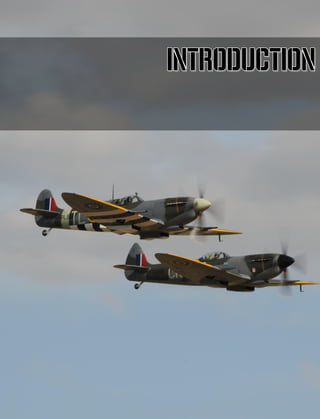
Figure 7: Pair of Spitfire Mk IX aircraft
For the rest of 1939 and the early part of 1940 Spitfires saw infrequent action during the rare occasions
when German bombers and reconnaissance aircraft came within range of their bases in England.
In May and early June 1940, in the period leading up to and during the Dunkirk evacuation, the Spitfire
first encountered its German equivalent, the Messerschmitt 109E, over northern France, Belgium and
Holland. Still no Spitfire fighter squadrons had been based outside Britain and the fighters had to
operate near to the limit of their radius of action from airfields in southern England. Nevertheless, the
fighter proved itself well and its appearance came as a nasty surprise for some of the Luftwaffe units
operating in the area.](https://image.slidesharecdn.com/dcsspitfireixflightmanualen-231006033519-04494cd4/85/DCS-Spitfire-IX-Flight-Manual-EN-pdf-21-320.jpg)
![DCS [Spitfire IX]
22 INTRODUCTION
Spitfire Mark IX
Early 1942 saw the introduction of the superb German Focke-Wulf 190 A on the Channel front, which
took the RAF by surprise. The next planned Spitfire general-purpose fighter, the Mk VIII, incorporated
several refinements developed in the previously developed Mk III prototype, and extensive re-tooling
was necessary to get production underway. The main improvement of the Mk VIII, however, laid in
the introduction of the new two-stage two-speed-supercharged Merlin engines, but this aircraft
involved a significant redesign of the basic Spitfire, and it would take time to produce in the numbers
required. The most expedient solution to make these available to the RAF was to adapt the readily
available Mk V airframe to this engine.
The Mk IX came into being as an impromptu countermeasure against the Fw 190 A. The first Mk IX
was basically a slightly strengthened Mark Vc airframe coupled to a heavier and more powerful Merlin
61 engine (fitted with a two-stage supercharger and intercooler). A four-bladed propeller was installed
to harness the increased horsepower. Apart from the longer nose profile, Mk IX’s another distinctive
feature was a revised system of underwing radiators (which featured two symmetrical, oblong section
radiator housings, one under each wing). Early-production Mk IXs retained the rounded fin and rudder
tip of the Mark V. However, the torque produced on take-off by the new, powerful engine was so great
that it was necessary to introduce the broad-chord, pointed-tipped rudder. Early Mk IXs, fitted with the
‘C’ type wing, were armed with two 20 mm Hispano cannons and four 0.303-in machine guns. Many
late-model Mark IXs, fitted with the ‘E’ type wing (which was introduced in 1944), exchanged the
ineffective 0.303s for two 0.50-in Browning machine guns (one per wing), mounted inboard of the 20
mm cannons.
Figure 8: Mk IX on the airfield at RAF Northolt
A few late Mk IXs had the cut-down rear fuselage and teardrop hood seen on other late-mark Spitfires.
The Mk IX lost nothing of the Spitfire’s famed maneuverability, whilst it offered a much better rate of
climb and speed than Mark V. At altitudes above 20,000 feet the Mk IX was outstandingly better than
its predecessor. A comparative trial revealed that Mark IX and Fw 190 were closely matched in terms
of performance. So great was the Mk IX’s success that the aircraft, which was conceived as a stopgap
solution, eventually became the second-most produced Spitfire variant. Throughout its service life the
Mk IX was extensively modified, both internally and externally. The three main sub-variants were: F
Mk IX (powered by 1,565 hp Merlin 61 or 1,650 hp Merlin 63 engines), LF Mk IX (1,580 hp Merlin 66)
and HF Mk IX (1,475 hp Merlin 70). The LF (Low-Altitude Fighter) variant, which entered service in](https://image.slidesharecdn.com/dcsspitfireixflightmanualen-231006033519-04494cd4/85/DCS-Spitfire-IX-Flight-Manual-EN-pdf-22-320.jpg)
![[Spitfire IX] DCS
EAGLE DYNAMICS 23
early 1943, frequently featured the so-called clipped wings (reduced wingspan for enhanced
maneuverability).
Initially (and unofficially) the standard F variant was referred to as ‘Mk IXa’, and the LF variant as ‘Mk
IXb’. The LF designation was in itself somewhat misleading, for this variant attained its maximum speed
at 22,000 ft (the standard F variant at 28,000 ft). Series production of the standard Mk IX went
underway in June 1942. No 34 Sqn RAF at Horn church was selected as the first for conversion, taking
deliveries the same month. No 611 Sqn RAF followed the suit in July, Nos 401 and 402 (Canadian)
Squadrons in August, and No 133 (US Eagle) Squadron in September. In the Mediterranean Theatre of
Operations the premier unit to re-equip with Mk IXs was No 81 Sqn (in January 1943), at that time
stationed in Algeria, followed shortly by No 72 in Tunisia. In Spring of 1943, the 31st and 52nd Fighter
Groups of the USAAF - the two American Spitfire outfits operating in the theatre – received shipments
of Mk IXs (and operated them well into 1944, before converting to P-51 Mustangs).
Figure 9: Spitfire Mk IXs in Formation
Summary
From spring of 1935, when the prototype assembly began, until February 1948, when the last Mk.24
was built, about 20,400 Spitfires were produced. (No consensus exists as to the exact number). This
number does not include the Seafire variant, which remained in production until March 1949.
The story of the Spitfire might have turned out differently, had its creator, Reginald Mitchell, still been
alive. Mitchell's character was that of an innovator, not a continuer. Most likely, he, much like Sidney
Camm of Hawker, would have created a number of new and different aircraft instead of squeezing all
the juice from the Spitfire. In any case, the Spitfire saw action from the beginning of the war until its
very end, and the Spitfire Mk.24 was regarded as one of the world's best piston engine fighters.
Compared with its prototype, the Mk.24 was a third faster, had twice the rate of climb, and its weapons'
burst mass was five times more. In addition, the Mk.24's takeoff weight, in comparison with the
prototype's, increased by 3080 kg, which, according to airline rules was equal to the mass of30
passengers (assuming 20 kg of luggage per passenger). These figures give an idea of how far the
development of the aircraft has gone.
The history of the Spitfire is closely linked to the development history of the Merlin and Griffon engines.
The power of the 27-liter Merlin increased from 1000 to 1600 HP, while engine weight increased by](https://image.slidesharecdn.com/dcsspitfireixflightmanualen-231006033519-04494cd4/85/DCS-Spitfire-IX-Flight-Manual-EN-pdf-23-320.jpg)
![DCS [Spitfire IX]
24 INTRODUCTION
only 15%. After some slight modifications, the aircraft received an upgrade: the 37-liter Griffon engine
with a power of 2230 HP. At the same time, its updated engine's mass was only 30% more than the
weight of the first Merlin.
Such is the technical history of the Spitfire. But this aircraft was not only a machine of war. For the
British and other Commonwealth citizens, the Spitfire was a symbol of the defense of Britain in the
difficult days of 1940, and by war's end had become a symbol of victory.](https://image.slidesharecdn.com/dcsspitfireixflightmanualen-231006033519-04494cd4/85/DCS-Spitfire-IX-Flight-Manual-EN-pdf-24-320.jpg)
![[Spitfire IX] DCS
EAGLE DYNAMICS 25
Spitfire Development Diagram
Fighter and fighter-bomber variants
SEAFIRE
Reconnaissance
Double-seater
Mk. IX
Mk.II
Mk.I
Late
Mk.I
Early
Mk.III
PR Mk.ID
(PR Mk.IV)
PR Mk.IC
(PR Mk.III)
PR Mk.IA
PR Mk.IB
PR Mk.VII
(PR Mk.IG)
PR Mk.IE
(PR Mk.V)
PR Mk.IX
PR Mk.XIII
PR Mk.IF
(PR Mk.VI)
F.7/30
Mk.IIA
Speed
Spitfire
Mk.IIB
Mk.IIC
MSS
Mk.VA
Mk.VB
hydroplane
Mk.IXC
Mk.IXE
hydroplane
Mk.XVIE
Mk.IA Mk.IB
Mk.III
prototype
Mk.XVIC
Mk.VC
Mk.I
Seaplane
project
F.37/34
Prototype (К5054)
Mk.VIII
Mk.IXE
Mk.VB
Mk.VI
(NF)Mk.VB
night fighter
Mk.VII
PR Mk.X](https://image.slidesharecdn.com/dcsspitfireixflightmanualen-231006033519-04494cd4/85/DCS-Spitfire-IX-Flight-Manual-EN-pdf-25-320.jpg)
![[Spitfire IX] DCS
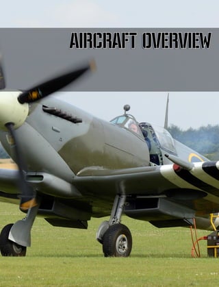
EAGLE DYNAMICS 27
AIRCRAFT OVERVIEW
Basic Informations
The Spitfire models IX, XI and XVI had specific letter prefixes which indicated the operational altitude
and role.
F – Fighter
PR – Photo Reconnaissance
L – Low
H–High
The addition of the letter (e) indicated a change in the armament. Instead of being equipped with four
7,69 mm guns, these versions had two 12,7 mm MGs. Besides, all versions had the same structural
shape.
Variant Key features
F IX
Engine “MERLIN” 61, 63 or 63A; two cannons caliber 20 mm .4 machine guns 7,69
mm.
LF IX Engine “MERLIN-66”; two cannons caliber 20 mm .4 machine guns 7,69 mm.
LF IX (e) Engine “MERLIN-66”; two cannons caliber 20 mm., 2 machine guns 12,7 mm.
HF IX Engine “MERLIN-70”; two cannons caliber 20 mm., 4 machine guns 7,69 mm.
HF IX (e) Engine “MERLIN-70”; two cannons caliber 20 mm., 2 machine guns 12,7 mm.
PR XI Engine “MERLIN” 61, 63 or 63A or 70, photo-reconnaissance equipment.
F XVI Engine “MERLIN-266”; two cannons caliber 20 mm., 2 2 machine guns 12,7 mm.
The 61 and 63 (A) versions of the MERLIN engine were equipped with the S.U. carburetor. The 66, 70
and 266 variants were equipped with the “BENDIX-STROMBERG” pressure carburetor.
All variants were equipped with a 4-blade ROTOL propeller.
The late Mk IX and XVI modifications had special teardrop-shaped fairing and cab lights.
Construction
The Spitfire is a cantilever monoplane of an all-metal construction with a lower wing position. The wing
consists of three parts: the center section, integrated into the fuselage, and two detachable consoles.
The shape of the wing is elliptical with a sufficiently thin profile (thickness ratio of 12.6% at the root
and 9.57% in the middle). There are two spars, but the frontal spar is significantly stronger than the
rear spar and assumes almost the entirety of the load. The thick lining attached to the front spar
contributes to an increase in torsional rigidity. The rear spar also works towards torsion and serves for](https://image.slidesharecdn.com/dcsspitfireixflightmanualen-231006033519-04494cd4/85/DCS-Spitfire-IX-Flight-Manual-EN-pdf-27-320.jpg)
![DCS [Spitfire IX]
28 AIRCRAFT OVERVIEW
fixing the ailerons in place. The ailerons are Frise type and are of an all-metal construction. Located
under the wing are the pneumatically-driven Shrenk type flaps, divided into inner and outer sections.
Truss ribs are present in the aircraft. The metal wing sheathing is load-carrying, smooth, and
countersunk riveted. Wing tips are available in three types: standard (rounded), short (almost
rectangular), and elongated/tapered. Aircraft fitted with shorter wingtips often had a spare set of
standard wingtips included.
The fuselage is semi-monocoque, which means it has a skeleton comprised of frames, spars and
stringers enclosed in a metal shell which receives part of the load. The cross-section of the fuselage is
of an elliptical shape. In the nose section of the fuselage, the sheathing is mounted in place by
countersunk rivets, while in the tail section this function is performed by rivets with lentiform heads.
The cowl panels are removable.
The layout of the fuselage was a classic for single-engine fighters of its time. Located in the front was
the powerplant comprised of the engine and propeller, and behind it, two gas tanks separated by a
fireproof bulkhead. Just behind the second bulkhead was the cockpit, which is closed off by a Plexiglass-
glazed windshield that had a rail-mounted section that slid back. The main feature of the Spitfire canopy
was its convexity: the bulges went 80 mm in each direction, providing the pilot improved vision of the
back and sides. The pilot could look back and through the rear-view mirror mounted on top of the
visor. The visor itself had flat surfaces on the front and sides that provided a clear image free of
distortion. The central section of the visor was made of bulletproof glass. Entry to the cockpit is by
means of a downwards-opening door on the left side of the aircraft. The sliding section of the canopy
can be locked in place in any intermediate position. In emergency situations the canopy can be
jettisoned instead of slid open - for which the pilot would simply pull the handles and then push the
canopy slightly upwards. Then he would pick up the incoming air flow. Oftentimes however the handle
would be torn when the pilot pulled on it, with the canopy remaining in place. For these situations, a
crowbar is located in a niche to the left of the cabin door would be used to shatter the canopy.
The pilot sat in a chair made of plastic (Bakelite), well above the floor of the deep cockpit. The chair
was composed of four stamped parts held together by duralumin plates. An Irvin parachute was fitted
into the seat pan. The seat height could be adjusted by means of the handle located to the right of the
pilot. Seat belts were equipped with a spring-retraction system. The pilot could loosen the straps to
move forward and then pull back. The rear areas of the pilot seat (the back of the headrest and spinal
section) were covered in armor sheets with a thickness of only 5 mm (capable of being penetrated
even by German 7.9mm armor-piercing bullets). The pilot flew the plane by a so-called "Spade-type"
control stick (with a gimballed upper section) and rudder pedals. English pedals were "two-stage."
Typically, the pilot's feet would be resting on the lower part, but during combat, when energetic
maneuvers required great effort from the pilot, the pilot would begin to use the upper sections. The
seventh frame, located behind the pilot's seat, is reinforced in order to perform the functions of the
crash pylon.
The dashboard has two sections. The main panel is made of 6 mm thick fabric-based laminate. On it
are the devices for motor startup and miscellaneous backup controls. The navigation devices are on
the aluminum panels, mounted on spring shock absorbers in the center of the main board. The compass
is located separately on the bracket under the dashboard.
There were no heating systems onboard the spitfire. There were provisions only for the electric heating
of the pilot's clothes and gloves, for which the pilot must use special wired gloves and insoles in his
flying boots. This system was ultimately unreliable and seldom used. Cabin ventilation was carried out
through the hatch on the right side in front of the wind shield. By turning the knob of the adjusting
screw, the pilot could regulate airflow.](https://image.slidesharecdn.com/dcsspitfireixflightmanualen-231006033519-04494cd4/85/DCS-Spitfire-IX-Flight-Manual-EN-pdf-28-320.jpg)
![[Spitfire IX] DCS
EAGLE DYNAMICS 29
Behind the cockpit was an additional fuel tank (installed separately), as well as various electrical and
radio equipment. These were accessed through a hatch on the left side. Almost the entirety of the tail
section of the fuselage was empty. To compensate for the increased weight of the engine compartment
in the frontal section, the aircraft battery and oxygen tanks were moved to the tail section.
The 19th frame is double, this place is actually the juncture of the fuselage and the detachable tail
section (integrated into the tailfin.) The 20th frame goes up to the top of the tailfin, turning in its spar.
The tail has a frame made of aluminum alloy and the same casing. The cantilevered stabilizer with an
elliptic planform is comprised of two halves connected together inside the rear fuselage. It is set parallel
to the axis of the aircraft. The tailplane frame and sheathing are all composed of an aluminum alloy.
The aerodynamic profile of the keel and stabilizer are also symmetrical.
The rudder and trimmers also have a metal frame, but are covered with a cloth soaked in lacquer.
Handlebars are horn-balanced. In the earlier models of the aircraft, the rudder had rounded top. Later
models introduced a wider rudder with a pointed end to compensate for the increased torque produced
by the propeller. Late Spitfire IXs also had elevated horn-balances for their elevators.
Installed on the Spitfire IXs are various modifications of the Merlin 60 Series engines - 61, 63, 66 and
70, all with differing nominal altitudes. The Merlin engine itself was a 12-cylinder liquid-cooling V-
engine with a working volume of 27 liters. The motor was mounted on a frame of tubular construction,
combining welded, riveted and bolted connections. On the 61 and 63 models were the older float-type
carburetors, while types 66 and 70 had the American floatless/membrane Bendix-Stromberg
carburetors with automatic control of mixture quality (height adaptation). All of these engines had
gear-driven two-stage centrifugal-type superchargers. The first speed worked regularly, while the
second speed would automatically activate at predetermined altitudes.
The motor is cooled with a mixture of glycol. It would circulate in the intermediate heat sinks that
cooled the air between the supercharger steps, as well as the fuel mixture right before it entered the
cylinders. The system's expansion tank was mounted on the engine gearbox. The radiators of the
engine cooling systems, supercharger, intermediate radiator and oil system are housed in two
symmetrical boxes located under the wings. Under the right wing was one section of the engine radiator
and the oil cooler. Under the left wing was the supercharger radiator and the second section of the
motor cooling system radiator. The radiators themselves were of a tunnel type. Adjustment of the
radiator scoops was automatic, performed by the thermostat. Interestingly, the system blocked the
activation of the second stage compressor at temperatures close to the maximum - 115°. (S.AR 1565J
& L Vol1 Sect 8 para 42.) The switch is mounted on the front section of the intercooler and is connected
to the supercharger actuation. The supercharger would be forced back to first speed (M.S.) in case
temperatures reached maximum allowable values.
The air for the carburetor is sucked out of the socket from under the wing center section. During dusty
takeoff conditions it is covered by an air-gate, and air intake is carried out from the engine
compartment. Aircraft later series were equipped with an additional filter, and because of this the air
intake was moved forward.
The engine was a system of individual (one per cylinder) jet exhaust pipes, the thrust of which slightly
increased flight speed.
Aircraft equipped with Merlin 66 engines used R12/4F5/4 propellers with wooden blades. The propeller
has four blades, with automatic pitch variation.
60 Series motors were fed high-quality 100-octane gasoline. In the Soviet Union, imported fuel was
used, or in its absence, 88 octave leaded petrol 4B-70. While the English engine didn't explode from
the use of this fuel, it was nevertheless incapable of reaching its maximum power.](https://image.slidesharecdn.com/dcsspitfireixflightmanualen-231006033519-04494cd4/85/DCS-Spitfire-IX-Flight-Manual-EN-pdf-29-320.jpg)
![DCS [Spitfire IX]
30 AIRCRAFT OVERVIEW
Fuel was stored in three fuselage tanks. Two of them are located in front of the cockpit in a
compartment between two fireproof bulkheads. Lying on the ribs, the bottom self-sealing fuel tank
with a capacity of 168 liters was considered the main fuel tank, as the engine drew fuel from it. From
the upper non-self sealing tank with a capacity of 218 liters, fuel dripped into the lower tank by means
of gas pressure. THe upper tanks are covered by a steel armor plate with a thickness of 4 mm. The
third tank (not mounted on all series) was installed behind the seat of the pilot. It had a capacity of
132 liters and was used only in conjunction with a large external tank as its filling greatly disturbed the
aircraft's balance.
The fighter could carry four types of external fuel tanks. Tanks with a capacity of 135 liters, 205 liters
and 410 liters had the form of a trough and lied close to the lower wing centersection. In this case, the
suction pipe in the tank was allowed passage. In jettisonning these tanks, they would first slide
backwards along rails, after which they would swing downwards. The fourth type of tank in the form
of a cigar had a capacity of 227 L and was suspended on the bomb racks under the fuselage. Switching
on fuel feed from the external tanks could only be done at an altitude above 600m.
The Spitfire undercarriage looked pretty unconventional. The main landing gears do not fold inwards
in the direction of the fuselage, instead folding outwards to the ends of the wing. This allowed for a
thinner wing, but limited track length to 5 feet 8.5 inches, making the airplane fairly unstable on uneven
floors. The undercarriage was deployed and retracted by means of a hydraulic system, the pump of
which is mounted on the motor. In case of pump failure, the undercarriage was deployed by means of
compressed carbon dioxide stored in a tank in the cockpit. The landing gears are equipped with Vickers
hydropneumatic shock absorbers. Wheels with a size of 600x170mm in the extended position stood
with a small collapse which was almost imperceptible to the eye. They are equipped with Dunlop air
brakes. In the retracted position, the wheels fit into a niche of the main panel spars. The gear leg and
about half of the wheel was closed off by a flap mounted at the gear leg. The tail wheel is free-moving,
capable of 360° rotation. Its leg is also equipped with a hydro-pneumatic shock absorber. In the early
series of Spitfire IXs, the tail wheel did not retract, while in latter models the rear gear leg folded
upwards and fit into the fuselage, closed off by hinged doors on each side of the hatch.
The pneumatic system, fueled by a Heywood SH-6/2 onboard compressor, controlled the landing lights,
wheel brakes, flaps, radiator scoops, weaponry, and the activation/deactivation of the supercharger
second-stage. The compressed air is stored in two cylinders located on the left side of the cockpit.
The fighter's electrical power source is a 750-watt generator on the engine and a 40 amp-hour battery
located in the fuselage rear. Energy consumers are the landing lights (retractable, placed under the
cockpit floor), the navigation lights, radio equipment, cabin lighting and gunsight lighting, as well as
the various signaling devices. The electric starter for motor startup was powered only by airfield
batteries, transported on a special trolley. The socket for use of an external power supply was at the
eighth frame under the wing fairings. During emergency takeoff from an unprepared airfield, a Coffman
combustion starter was used to start the engine. Network voltage is equal to 12W.
The Spitfire IX had a de-icing system that used a mixture of distilled water and ethylene glycol to wash
the canopy visor. The sprayer was mounted in the bottom edge of the visor. The system was driven
by a manual pump placed on the starboard side of the cabin.
At high altitudes, pilots used oxygen masks. The oxygen was stored in a 6 liter cylinder at the tail of
the aircraft. The English gas system dispensed oxygen not constantly, but periodically, depending on
pilot needs.
The fighter was equipped with a VHF radio, types TR-1133, TR-1133A or TR-1143. TR-1143, the latest
model at the time, was matched with an A.1271 radio navigation device, which itself is a primitive blind
landing system. The radio station was mounted on a retractable platform which greatly facilitated its
maintenance. In England, the machine essentially had an A.R.I. 5025 IFF transponder, with a R-3067](https://image.slidesharecdn.com/dcsspitfireixflightmanualen-231006033519-04494cd4/85/DCS-Spitfire-IX-Flight-Manual-EN-pdf-30-320.jpg)
![[Spitfire IX] DCS
EAGLE DYNAMICS 31
transmitter. Its unit was mounted on brackets on the left side next to the tail. These transponders were
considered confidential and were supplied with an explosive charge rigged to self-destruct. Pilots forced
to land in enemy territory were ordered to destroy the device. The main radio used an antenna
stretched which extended upwards behind the cockpit canopy and ran towards the tip of the keel. The
mast was based on the crossbar of duralumin profiles under the fairing. The transponder antennae
went from the fuselage sides to the ends of the stabilizer.
The Spitfire IX's armor protection was rather lackluster. Generally, it consisted of 5.4 mm thick steel
plates that protected the pilot's back, knees, and back of the head, as well as the upper fuel tank. A
visor of bulletproof glass with a thickness of 38 mm was mounted on the canopy windshield. The
bottom and sides of the fuel tanks and ammunition compartments are closed off by duralumin plates
of 3-4mm thickness.
The aircraft weapons were of two types - C and E, depending on the wingset installed on the fighter.
In the first case, the aircraft panels usually housed two British Hispano 20-mm cannon with a reserve
of 120 rounds on the barrel and four Browning 7.69 calibre machine guns with a supply of 350 rounds
per gun. The guns were mounted close to the fuselage, just behind the niches of the chassis. The
barrels extended behind the leading edge and were closed off by a fairing. The cartridge feed
mechanisms could not fit within the profile of the wing; designers were forced create small teardrop-
shaped protrusions for this reason.
Machine guns were mounted farther away from the axis of the aircraft - between the reinforced ribs.
For the convenience of placing their ammunition boxes the guns were moved longitudinally by 152
mm. Access to the guns is through hatches with hinged lids located on the underside of the wing. To
improve gun cooling, pipes were mounted on the gun barrels - the front edges of these pipes were
shaped in the form of the wing. For protection against dirt and dust before flight, as well for the
improvement of the aircraft's aerodynamic characteristics, the holes in the front edge of the wing were
sealed up with percale and covered with red lacquer. The first shots fired would then break through
them. The machine guns were fed from boxes by sectionalized metal belts. These used-up belts and
cartridge cases were ejected from the aircraft through gaps under the wing.
But in some rare models, instead of machine guns, two more cannons were mounted on the aircraft.
In this case, the ammunition counts were 145 rounds for the inner guns and 135 for the outer guns.
The Spitfire IXC could also mount a bomb weighing up to 227 kg on the underside of the fuselage.
The reinforced wing type "E" allowed for more powerful weapons. One cannon with a reserve of 120
rounds and one 12.7 mm machine gun with 250 rounds could be mounted on each wing. The Spitfire
IX also saw the implementation of underwing bomb racks; thus total bomb load could be raised to 454
kg. Usual loadouts saw a bomb weighing 227 kg mounted under the fuselage and an additional two
weighing 113 kg mounted under the wings. Munitions used were of the following types: high-explosive,
fragmentation, incendiary, armor-piercing high-explosive and smoke - of both English and American
production. Spitfire IXe also saw the use of rocket weaponry - a pair of unguided 76 mm rockets.
Depending on the weight of the warhead, these rockets could weigh 11.3 kg or 27.2 kg. In either case,
the IX could have a combat load of two rockets and one 227-kg bomb.
The weapons compartments were warmed in-flight with warm air, which first passed through the
radiator. Aircraft with wing type "C" also used air for heating the machine guns, first heated in the
exhaust system of the engine.
The Spitfire had an electropneumatic weapons control system. In earlier series of the aircraft, aiming
was done through a GM 2 collimating optical sight, and in later series through a Mk.IID gyroscopic
sight. This sight made it possible to preset the range of opening fire and target characteristics (i.e.
target size already known to the pilot.) Result monitoring was provided by the G-45 or G-42B camera](https://image.slidesharecdn.com/dcsspitfireixflightmanualen-231006033519-04494cd4/85/DCS-Spitfire-IX-Flight-Manual-EN-pdf-31-320.jpg)
![DCS [Spitfire IX]
32 AIRCRAFT OVERVIEW
gun mounted at the root of the left wing. The camera gun could be activated simultaneously with the
cannons and machine guns, or separately from them.
The on-board equipment includes the Plessy six-barreled signal rocket launcher system, with differing
rocket colors for varying code messages. They were fired up by means of electrical signals. A supply
of water, emergency rations in a sealed tin, and an inflatable raft with a tank of carbon dioxide (in the
event of an emergency landing) were also included on board.
Figure 10: SPITFIRE Mk. IX with standard wingtip
Specifications
Specifications for the SPITFIRE IX are:
• Wingspan:
- standard wings 36 ft 7 in
- clipped wings 32 ft 7 in
• Length 31.5 ft
• Height:
• - To top of propeller 11 ft 8 in
• - To center of propeller spinner: 6 ft 3 ½ in
• - To wingtips: 5 ft 4 in (approx)
• Propeller clearance: 11 in
Fuselage:
• Width (max): 3 ft 6 in](https://image.slidesharecdn.com/dcsspitfireixflightmanualen-231006033519-04494cd4/85/DCS-Spitfire-IX-Flight-Manual-EN-pdf-32-320.jpg)
![[Spitfire IX] DCS
EAGLE DYNAMICS 33
• Length (overall) 20 ft 10 in
• Height (max): 6 ft 9 in
Wings:
• Wing profile: N.A.C.A. 2200
• Average chord: 7 ft 1 in
• Incidence: 2° at root, -0.5° at wingtip
• Dihedral: - 6°
• Wing area including ailerons and flaps: 242 ft²
• Ailerons, total: 18.9 ft²
• Flaps, total: 15.6 ft²
Tail:
• Span (over elevators): 10 ft. 6 in
• Chord (max): 4 ft
• Incidence: 0°
• Lateral angle: 0°
• Area including elevators: 31.46 ft²
• Elevators, two, with trimming tabsl: 13.26 ft²
• Trimming tabs, each: 0.38 ft²
Fin and rudder:
• Fin area: 4.61 ft²
• Rudder area, with trimming tab: 10.7 ft²
• Trimming tab: 0.7 ft²
Gear:
• Track: 5 ft 8.5 in](https://image.slidesharecdn.com/dcsspitfireixflightmanualen-231006033519-04494cd4/85/DCS-Spitfire-IX-Flight-Manual-EN-pdf-33-320.jpg)
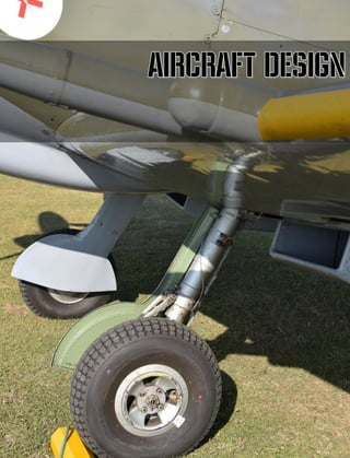
![[Spitfire IX] DCS
EAGLE DYNAMICS 35
AIRCRAFT DESIGN
Main elements
Figure 11: Aircraft structure
1. Wingtip
2. Aileron
3. Right wing
4. Header tank (cooling tank)
5. Engine “MERLIN-66”
6. Exhaust manifolds
7. Generator
8. Upper fuel tank
9. Lower fuel tank
10. Engine struts
11. Flameproof bulkhead
12. Windscreen
13. Jettisonable hood
14. Instrument panel
15. Pilots access door
16. Access door radio compartment
17. Tail
18. Elevator
19. Tail unit
20. Rudder
21. Rudder trimming tab
22. Elevator trimming tab
23. Tail wheel unit
24. Tail portion main plane fillet
25. Main plane attach fitting, rear
26. Browning guns bays
27. Magazine door
28. Main wheel
29. Main wheel leg strut fairing
30. Hispano gun fairing
1 2 3 4 5 6 7 8 9 10 11 12 13 14 15 16 17 18 19 20 21 22
23
24
25
26
27
28
29
30
31
32
33
34
35
36
37
38
39
40
41](https://image.slidesharecdn.com/dcsspitfireixflightmanualen-231006033519-04494cd4/85/DCS-Spitfire-IX-Flight-Manual-EN-pdf-35-320.jpg)
![DCS [Spitfire IX]
36 AIRCRAFT DESIGN
31. Hispano gun
32. Main wheel strut
33. Hispano gun adjusting ring
34. Top boom main spar
35. Jettisonable fuel tank
36. Root attach main plane front spar
37. Engine mounting
38. Suppressor
39. Oiltank
40. Rotol propeller
41. Spinner
Fuselage
The fuselage is of an all-metal semi-monocoque construction, designed with a load-carrying skin and
detachable tail section. The fuselage may be divided into three parts: front, main and rear. The frontal
section houses the fuel tanks, and just behind the tanks is the pilot's cockpit which is closed by a
jettisonable sliding canopy made of transparent material. Transparent glazing is also present behind
the cockpit and in the upper part of the fuselage for better rear visibility. The canopy windshield is
reinforced with armored glass in the central part. To enter the cockpit, a hinged door is on the left side
of the fuselage, attached to the main fuselage spar. Behind the visor in the cockpit are rails for the
gunsight light filter which is used by the pilot to minimize glare in very bright conditions. In normal
conditions, the gunsight filter is kept in the retracted position mounted on the rails under the canopy
windshield.
Hatches for maintenance of the components of the aircraft are found on the skin of the fuselage.
Mounts for equipment and controls are present inside in different places of the aircraft structure. Armor
plates are also installed behind the fireproof bulkheads as well as behind the pilot seating.
The fuselage consists of five spars: two lower spars, two main spars, and one upper spar, and and 15
frames, numbered from 5 to 19. The frames on the frontal part of the fuselage until the 11th are open
and U-shaped, followed by closed frames. The lower spar is box-shaped, formed by two angle bars
from the 5th to the 10th frame. After the 10th frame, the lower spar has a V-shaped profile. The main
spars are located at the centerline of the fuselage and have a U-shaped profile. Both spars are
reinforced by steel sections with a thickness of 1.016 mm. The right side spar is reinforced from the 5-
th to 7-th frame, while the left side rail is reinforced from the 5-th to 6 inches from the 8-th frame.
From the 14 th to 19-th frame, the main spars are of a Z-shaped profile. The upper spar is V-shaped.
The main spars have leveling points on the sides of the cockpit for spirit leveling. The covering is of a
duralumin alloy, covered with aluminium, riveted to the frames and supported by Z-shaped stringers.
The tail part of the fuselage is detachable and consists of the tail and and stabilizers. The tail section
is bolted to the fuselage on the 19-th frame.
For convenience of description, the fuselage can be divided into three parts: front, main and rear.](https://image.slidesharecdn.com/dcsspitfireixflightmanualen-231006033519-04494cd4/85/DCS-Spitfire-IX-Flight-Manual-EN-pdf-36-320.jpg)
![[Spitfire IX] DCS
EAGLE DYNAMICS 37
5 6 7 8 9 10 11 12 13 14 15 16 17 18 19
Figure 12: Fuselage scheme
Front Part
Begins with the 5th frame, which is also the firewall until the 11th frame. In the front part are the fuel
tanks and the cockpit. The 8th frame forms a closed loop, and in the middle of the top of the frame
are mounted two strut supports, which are connected to the nodes connecting the motor and the main
spars on the 5th frame. Installed after mounting the bottom of the fuel tank.
The fireproof bulkhead is attached to the 5th frame. Four bars which form the hinge of the front wing
spar are mounted at the bottom of the 5th frame. The mount for the of the auxiliary wing spar is
installed in the bottom of the 10th frame. The spar mounts are located behind the fuselage skin.
The fireproof bulkhead consists of a sheet of asbestos located between the two metal sheets and
reinforced by vertical and horizontal load-bearing elements. The armor plates are bolted to the back of
the upper part of the bulkhead.
The top mounts of the engine mount are bolted to the main spars and struts. The bottom nodes are
attached to the lower longerons and to the beam forming the fuselage portion of the main wing spar.
The bottom of the 6th and 7th frames are covered with a layer of cork and are the supports for the
bottom of the tank. Frame #9 is supported in the lower part by one transverse and two diagonal
elements that go up to the 8th frame and support thе pedal nodes. The cabin mount is installed
between frames 8 and 11. A load-bearing element (which is also the support for dashboard) of an
arcuate shape supports the cabin mount on frame 8. The pilot access door attached by the lower part
to the main spar is installed on the left side of the fuselage between frames 9 and 10. The top of the
door has two two-position locks that hold the door in the closed and half-open position. The lock lever
is located closer to the frontal lock. Turning the handle forward and down opens the locks. The canopy
sliding rails are installed on the top of the doors. The half-open position of the canopy sliding door is
designed such that it will not suddenly close and hurt the pilot even during an emergency landing.
Frame 11 is of a closed oval-shape and has transverse and diagonal stiffeners to which the pilot
seating is attached. Armor plates are mounted to the top of the frame on four studs and curled nuts.
Main part
The main part is formed from frames 11-19. The frames are of a closed oval-shape, having identical
structures, characterized by a decrease in size further down the aircraft body (towards the tail section).](https://image.slidesharecdn.com/dcsspitfireixflightmanualen-231006033519-04494cd4/85/DCS-Spitfire-IX-Flight-Manual-EN-pdf-37-320.jpg)
![DCS [Spitfire IX]
38 AIRCRAFT DESIGN
Between frames 11 and 12 the upper part of the fuselage skin is made of a transparent material to
improve rear visibility. Mounted under the transparent part of the fuselage sides are the canopy's sliding
rails. On the starboard side of the cockpit, the rails mounted on the edging. Reinforcing elements are
mounted between frames 12 and 13, the crossing of which supports the radio antenna mast. Load
balancing elements are found between frames 17 and 18 to compensate for the increased weight of
the engine.
Tail part
Integrates with the tail fin and is detachable. The tail section is attached to the 19th frame using 52
bolts placed on the frames and four pins on the lower side longerons. The 19th frame is made of an
angle bar, while the remaining frames are flat. The tailplane spar is bolted to a the reinforced 20th
frame, which is the front fin spar. The auxiliary spar of the stabilizer is attached to the auxiliary tailfin
spar to which the rudder is attached. The tailfin spars are connected to each other by ribs. The tailfin
sheath is riveted on the left side while the right side is attached by screws to the wooden elements
bolted to the ribs. The stabilizer sheathing is attached in the same way.
Canopy frame
The canopy frame is made of steel, fastened by bolts to the cabin edge. The central section of the
windshield, bolted to the frame, is a bulletproof visor with a thickness of 1 ½ inches. A rubber layer
between the glass and the frame ensures that the visor is sealed in place. The rear frame is shaped to
ensure a tight fit of the sliding canopy in the closed position.
The sliding section of the hood seals the cockpit from the windshield until frame 11, and is moved on
rails mounted on the cabin edge. On the front of the hood is a locking that holds the hood in the open
position - latching onto frame 11; as well as in the closed position - latching onto the visor frame. The
lock is opened by turning the levers connected by a rope (for pilot convenience). Turning the levers
forward opens the lock, and the cover slides forward. Turning the levers back opens the lock and the
hood slides back. When the aircraft is parked with a closed hood, the lock is opened by a small spring-
loaded button on the top of the visor. On the transparent part on the left side of the hood is a pane
for use in case of a dirtied windshield. The sliding part of the canopy has an emergency jettison system.
Next to the lock is a rubber ball suspended on a rope, which, when pulled, removes the brass pins from
the canopy hood.
The pilot seating is cast of a phenol-formaldehyde resin (Bakelite), with an underside compartment for
the emergency parachute. Mounted on the frame with an elevation adjustment mechanism (found on
the right side) on the 11th frame. The mechanism quadrant mechanism has 6 notches, with elevation
intervals of 4 inches. Armor plates are attached at the back of the seat. Seatbelts with locking system
via cable runs and spring stopper are also present on the pilot seat. A keylock is mounted on the
starboard side. When moving the lock latch forward or backward, the seatbelts withdraw from the
stopper and allow the pilot to lean without spring resistance. When returning the handle lock to the
rear position, the spring is fixed to the stopper and the seatbelts' movement is blocked.
To the top of frame 11, a cylindrical shape headrest is mounted on the seat.](https://image.slidesharecdn.com/dcsspitfireixflightmanualen-231006033519-04494cd4/85/DCS-Spitfire-IX-Flight-Manual-EN-pdf-38-320.jpg)
![[Spitfire IX] DCS
EAGLE DYNAMICS 39
Wing
Wing modification "C" consists of two detachable parts. Mounted on the sides of the fuselage, the wing
and the lower surface of the fuselage are coplanar. Metal Frise type ailerons are attached to the rear
of the wing closer to the tips. Two-piece Shrenk-type flaps are hung along the span of the aileron to
the fuselage. The flaps are divided into two parts at the point of fracture of the wing and are driven
pneumatically. The wingtips are removable and have space for the installation of navigation lights.
The detachable part of the wing has a spar structure: it has a main and auxiliary spar plus 21 ribs. The
sheathing is made of a duralumin alloy.
The wing mounts are found at the bottom of the two fireproof bulkheads, the lug mounts for the
mooring are lead out to the contour of the fuselage on both sides.
Figure 13: Wing structure
Main spar
The front edge of the main wing spar and formed as a single unit, which is attached to the main part
of the wing. The main spar is composed of square shelves and walls in between.The spar cap (pictured)
is formed of a steel profile of square section of reducing size, inserted telescopically. This facilitated
production and simplified the change of the spar cap sizes in scale. The wall is attached to the rear
side of the spar caps. The form of the caps vary from the square section to a tee, and ends in a corner
as it approaches the wingtip. The root of the wing spar has two clamps for connecting to the hinge
fittings on the 5th frame.
20 19 18 17 16 15 14 13 12 11 10 9 8 7 6 5 4 3 2](https://image.slidesharecdn.com/dcsspitfireixflightmanualen-231006033519-04494cd4/85/DCS-Spitfire-IX-Flight-Manual-EN-pdf-39-320.jpg)
![DCS [Spitfire IX]
40 AIRCRAFT DESIGN
The rib caps are made of an angular profile with diagonal reinforcing of a channel section. The ribs are
bolted to the spar, and at the wing root the rib spacing is reduced, a reinforcing elements are in place
for holding the hinge fitting of the main column.
The leading edge sheathing consists of an upper and lower part. Both parts are riveted to the ribs and
spar. Riveted to the sheathing between the ribs are Z-shaped stringers. On the bottom of the sheathing
and in the flange of the spar are hatches for access to the internal cavity.
Main part of the wing
Consists of an auxiliary spar and ribs. The rib caps are made of a section and reinforced by diagonal
struts. The ribs of the root of the removable part of the wing are also reinforced. The auxiliary spar
consists of rib caps with an angle bar and web. The spar is divided into three sections by two ribs
extending beyond the spar for aileron linkage. A panel on the flaps is supported by load-bearing
elements of the angle bar. A mount fitting for the auxiliary spar is installed on the 10th frame.
The upper part and a large part of the lower sheathing is riveted to the flanges of the ribs and
longerons; part of the lower sheathing by the wingtips of the detachable wing section is fastened with
screws to the wooden elements, which are attached to the ribs and spars.
Below the detachable wing section is a compartment for accommodating the undercarriage and wheels
in the retracted position. The compartment is sealed from the rest of the detachable section. There is
also a compartment near the roots for the radiators, which are closed off by cowlings, forming a tunnel.
Automatically controlled grates are installed at the rear of the cowling. Warm air is taken from the back
of each tunnel for use in heating the machine gun and cannon compartments to prevent weapons
malfunction due to the lubricant freezing in the firing mechanisms.
The gap between the wing and fuselage skin is closed off by cuffs.
Wingtip
One unique feature of the aircraft was the presence of wingtip replacements, which could be replaced
during operation of the aircraft. In total there are three types of wingtips: standard, extended, and
shortened. Standard and extended wingtips are attached to the nodes to the wing spars directly behind
the aileron, while the shortened variant is fixed with screws and captive nuts to the skin. When installing
a shortened wingtip, the navigation light sockets were installed inside a rib. Extended wingtips were
rarely used on Spitfire IXs, and were seen mostly on F.IX. modification models. The shortened endings
were installed on some of the L.F. Mk. IX models. Some aircraft with shorter wingtips have an extra
fuel tank installed behind the pilot seating, however on these aircraft replacing the shortened tips with
standard ones was prohibited. However, tests in the Boscombe Down center showed that shortened
wingtips did not provide the aircraft with any boosts in its performance.](https://image.slidesharecdn.com/dcsspitfireixflightmanualen-231006033519-04494cd4/85/DCS-Spitfire-IX-Flight-Manual-EN-pdf-40-320.jpg)
![[Spitfire IX] DCS
EAGLE DYNAMICS 41
Figure 14: Standard wingtips
Armor protection
The following armor plates are installed on the aircraft:
1. Front of fuel tank, 4mm](https://image.slidesharecdn.com/dcsspitfireixflightmanualen-231006033519-04494cd4/85/DCS-Spitfire-IX-Flight-Manual-EN-pdf-41-320.jpg)
![DCS [Spitfire IX]
42 AIRCRAFT DESIGN
2. Fuel tank cowling, 10SWG/3.251mm
3. Bottom of windscreen, 4mm
4. Bulletproof windsreen, 1.5in
5. Behind pilot seating, 4mm
6. Behind pilot headrest, 6mm
7. Under pilot seating, 4.064mm
8. Deflector plates, 6mm.
9. Ammunition boxes, top and bottom skin, 10 S.W.G./3.251mm
10. Front of ammunition boxes, 6mm.
11. Additional 6mm head protection armor (in later variants)
12. Additional pilot protection from behind, 7 mm
The armor plates on the front of ammunition boxes were removed on later models of the aircraft, and
were replaced with additional armor plates of behind the pilot seating and headrest, with a thickness
of 7mm and 6mm respectively.
Figure 15: Aircraft armor plate locations
1
2
3
4
6
11
12
5
8
7
9
9
10
10](https://image.slidesharecdn.com/dcsspitfireixflightmanualen-231006033519-04494cd4/85/DCS-Spitfire-IX-Flight-Manual-EN-pdf-42-320.jpg)
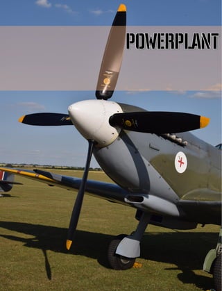
![DCS [Spitfire IX]
44 POWERPLANT
Powerplant
The Spitfire IX powerplant consists of a Rolls-Royce 60-series Merlin aircraft motor, and a Rotol
R12/4F5/4 hydraulic variable-pitch aircraft propeller with wooden blades.
The Spitfire IX also has a Merlin 66 (RM 10 SM model) liquid-cooled, 12-cylinder V-twin four-stroke
internal-combustion engine with a capacity of 27 litres, equipped with a Bendix-Stromberg pressure
carburetor capable of operating under negative G-loads, and a two-stage, two-speed drive centrifugal
compressor with an intermediate cooler.
The engine is driven by a four-blade variable-pitch propeller. Propeller pitch is changed using the
constant-speed regulator installed at the front of the engine under the propeller gearbox.
The Rotol R12/4F5/4 in-flight-variable pitch propeller features wooden blades, manufactured through
the Jablo or Hydulignum methods of propeller production, with a “fine pitch” angle of 22° 20’, and a
propeller diameter of 10’9”.
The engine is mounted on a tubular steel frame motor attached to the fire-retardant frame. The pipes
and electronic wires to the engine mount by clamps.
The gear and drive ratios of the Merlin 66 engine’s centrifugal supercharger are selected in such a way
as to ensure maximum power at low altitudes.
The oil tank is mounted under the engine crankcase; oil radiator in the tunnel under the left plane. The
expansion tank of the liquid cooling system is installed in the front part of the engine under the propeller
drive, and the the 2 radiators of the cooling system are located in the tunnels under each plane. The
radiator for the cooling systems of both the two-stage centrifugal supercharger and the intercooler is
located respectively under the right plane.
Exhaust pipes are of the fishtail type, with one for each cylinder.
Engine management is handled by the throttle quadrant installed on the right side of the cabin. The
throttle quadrant features levers controlling throttle, propeller pitch, and engine shutdown.
Engine
History
In 1932, Sir Henry Royce wished to develop an engine that had the reliability of his Kestrel design,
combined with the power of the 1931 Schneider Trophy-winning “R” engine in the Supermarine S6B
racing seaplanes. The result was called the P.V.12, a 27 litre, V-12, liquid cooled, single-stage
supercharged engine (P.V. standing for Private Venture).
Royce died on 22nd April 1933 without ever seeing this engine run and without knowing it would
eventually become his most produced design. Just six months after his death, the first P.V.12 engine
run was conducted on 15th October 1933.
The prototypes of two other private ventures, the Hurricane and Spitfire fighter aircraft, were designed
around the 890 hp (663 kW) Merlin ‘C’. The early engine design’s performance needed improvement
but was sufficient to demonstrate the potential of these new low-wing monoplane fighters. Rolls-](https://image.slidesharecdn.com/dcsspitfireixflightmanualen-231006033519-04494cd4/85/DCS-Spitfire-IX-Flight-Manual-EN-pdf-44-320.jpg)
![[Spitfire IX] DCS
EAGLE DYNAMICS 45
Royce even contributed £7,500 towards the total cost of £15,000 (equivalent to about £850,000 today)
of the Spitfire prototype, K5054, which first flew on 5th March 1936.
By 1937, after significant alterations to the cylinder head design, the Merlin II was capable of 1,030 hp
(768 kW). All Spitfires and Hurricanes in RAF service at the outbreak of war in September 1939 were
fitted with the Merlin II, with the Merlin III being fitted in ever larger numbers by the Battle of Britain
in 1940.
Merlin development never ceased and more and more power was extracted from the engine using
improved superchargers and fuels. In 1942 the Spitfire Mk IX was equipped with the two-speed, two-
stage supercharger, 1, 280 hp (954 kW) Merlin 61. The Mk IX’s performance was improved both in
speed and ceiling and immediately outstripped the opposition to gain outright air superiority. This
improved Merlin was also used in other aircraft, the most famous application being the North American
P-51 Mustang which became one of the most successful fighter aircraft of WW2.
Engine Specifications
Manufacturer: Rolls-Royce Limited
Years of production: 1933 - 1950
Type: four-stroke V-shaped twelve-cylinder liquid-cooled
Technical Characteristics
Capacity: 27 L
Power: 1 290 h.p. (962 kW) at 3000 rev/min during takeoff mode
Power density: 35.6 kW/L (47.8 h.p./L)
Stroke cycle: 152.4 mm
Number of cylinders: 12
Cylinder diametere: 137.16 mm
Valves: 2 inlet and 2 intake valves per cylinder
Compressor: two-stage two-speed, with intermediate cooling between the second stage of the
compressor and the motor
Fuel type: Gasoline with 100 octane rating
Lubrication system: Dry sump with one oil pump
Cooling System: Liquid pressure coolant - a mixture of 70% water and 30% ethylene glycol.
(Supercharger cooling system is independent of the engine cooling system)
Fuel consumption: 177 L/h - 400 L/h
Specific power by weight: 1.58 kW / kg (2.12 hp / kg) at maximum power
Aircraft Dimensions
Length: 2253 mm
Width: 781 mm
Height: 1016 mm
Dry weight: 744 kg (source: Wikipedia)](https://image.slidesharecdn.com/dcsspitfireixflightmanualen-231006033519-04494cd4/85/DCS-Spitfire-IX-Flight-Manual-EN-pdf-45-320.jpg)
![DCS [Spitfire IX]
46 POWERPLANT
Engine Type V-type, liquid-cooled, geared, equipped with two-stage two-speed
supercharger with liquid cooling and intercooler
Number of Cylinders 12
Cylinder Arrangement 2 blocks of 6 cylinders with an angle of 60°
Piston – diameter and throw 5.4 * 6 inches
Working Capacity 1648 in3
, 27 liters
Compression Ratio 6
Supercharger 2-stage, 2-speed
Gear ratio First speed - 1:5,79; Second speed - 1:7,06
Design Description
Merlin 66 (RM 10 SM model) liquid-cooled, 12-cylinder V-twin four-stroke internal-combustion engine
with a capacity of 27 litres, equipped with a Bendix-Stromberg 8D-44-1 pressure carburetor capable of
operating under negative G-loads, and a two-stage, two-speed drive centrifugal compressor with an
intercooler for cooling the air-fuel mixture supplied to the cylindersх
Figure 16: A Rolls-Royce Merlin 66 Engine
2 blocks with 6 cylinders, each of which are located on the beveled upper surfaces of the crankcase.
One block is comprised of the cylinder heads, cylinder skirts made from a light alloy, and steel cylinder
liners. The motor cylinder is a steel liner, fixed by its upper section to the block. The lower section of
the liner, part of the unit with a loose fit, is sealed with a rubber ring tightened by a nut. Each cylinder](https://image.slidesharecdn.com/dcsspitfireixflightmanualen-231006033519-04494cd4/85/DCS-Spitfire-IX-Flight-Manual-EN-pdf-46-320.jpg)
![[Spitfire IX] DCS
EAGLE DYNAMICS 47
has two exhaust and two suction valves. The exhaust valves are hollow and cooled by sodium; the
suction valves are solid and do not have sodium cooling. The adjacent surfaces of the valves are
covered by Brightray, a nickel-chromium alloy. The valves are actuated by means of a roller camshaft
installed in the center of the cylinder head through the spreader bar. In order to cool the cylinder block
cavities are in place for the circulation of coolant material.
In front of the motor is a reduction gear, comprised of a pair of cylindrical gears, one of which is
mounted on the flange of the crankshaft, and the other on the flange of the gearbox shaft. On the
tailshaft are slots for the installation of the in-flight-variable pitch rotorhead.
The rear of the motor houses the gearbox which transmits torque from the crankshaft to the
consumers: the upper and lower vertical transmission, the two magnetos installed on both sides of the
motor, and the pump of the main cooling system. The intermediate gear drives the rotation of the oil
pumps, the hydraulic pump, the fuel pump and the electric generator. The drives for manual scrolling
and the electric starter are also fitted in the box.
Two-speed two-stage supercharger is mounted on the rear of the drive, while a dual-chamber
carburettor with automatic height adaptation and boost regulator is mounted by the entrance of the
supercharger. On the right side of the motor housing is the centrifugal pump for both the supercharger
cooling system and the intercooler.
Figure 17: Motor assembly. View from starboard side
1. Scavenge return-oil to tank 2. Fuel priming inlet
10
6
6 7 9
1
3
2
4
5
8
11](https://image.slidesharecdn.com/dcsspitfireixflightmanualen-231006033519-04494cd4/85/DCS-Spitfire-IX-Flight-Manual-EN-pdf-47-320.jpg)
![DCS [Spitfire IX]
48 POWERPLANT
3. Wheelcase breather connection
4. Magneto booster coil connection
5. Magneto earthing connection
6. Engine feet
7. Oil pressure gauge connection
8. Oil thermometer connection
9. Main oil supply to pressure pump
10. Crankcase breather connection
11. Connector from surge tank to main engine cooling
system.
Supercharger
The gear-driven centrifugal-type supercharger mounted on the Merlin engine has a two-stage
compressor that raises air pressure at the entrance to the engine cylinders in order to increase both
the coefficient of admission and engine power, as well as to maintain a constant air pressure at the
entrance to the cylinders during increases in altitude.
It consists of two centrifugal type impellers located on the same shaft. The shaft is rotated through
three gear centrifugal clutches. Couplings absorb inertial loads caused by high acceleration during
startup, while axial loads are absorbed by the spring-loaded drive shaft. Torque is transmitted to the
supercharger by means of a crown gear with a coupling during operation at the first speed, while the
other two gears switch on upon setting the supercharger to operate at the second speed. Clutch control,
which determines through which gear torque is transmitted, is actualized by means of the claw arm
system, which in turn are driven by a hydraulic cylinder via an intermediate roller. The hydraulic cylinder
is driven by oil pressure from the pump line. The piston valve of the hydraulic cylinder is controlled via
a lever that moves by the pneumatic actuator of the supercharger speed control.
Shifting between the first “M.S” (medium supercharger) and second “F.S” (full supercharger) speeds
may be performed automatically, or manually through a 2-stage switch in the cabin. For automatic
operation, the toggle switch on the right side of the dashboard must be in the “AUTO” position. In this
case, the signal on the solenoid actuator will be coming from the altitude switch, which at a certain
altitude will energize the solenoid drive with a supply of compressed air. The actuator is connected via
a lever to the slide valve of the speed clutch control hydrocylinder. The aneroid of the altitude switch
is set to trigger at an altitude of 14,000 feet (switching from first to second speed) on a climb, and
12,500 feet (switching from the second to the first speed) on a descent. For manual operation, the
toggle switch has a second position - "M.S." - which cuts off the circuit to the altitude switch and sets
the supercharger to the first speed. On the dashboard is a lamp-switch which lights up upon a shift in
supercharger speed. The required pressure in the pneumatic system for operation of the pneumatic
actuator is 150 lb/in2
.
Intercooler
Tubular-type intercooler with liquid cooling, designed for reducing the temperature of the combustible
mixture supplied to the cylinders, installed between the supercharger outlet and the primary inlet
manifold. An expansion tank for both the supercharger cooling system and the intercooler is mounted
on the fireproof bulkhead.](https://image.slidesharecdn.com/dcsspitfireixflightmanualen-231006033519-04494cd4/85/DCS-Spitfire-IX-Flight-Manual-EN-pdf-48-320.jpg)
![[Spitfire IX] DCS
EAGLE DYNAMICS 49
Figure 18: Intercooler exterior
1. Coolant material outlet stack (leading to the expansion tank)
2. Inlet stack for coolant material from the supercharger
3. Boost gauge pressure tap
4. Entry for the combustible material from the supercharger
5. Exit into the main inlet pipe for the cooled combustible material
Carburetor
The combustible mixture is formed by means of the dual-chamber air intake of the Bendix Stromberg
injection-type carburetor (which is a ready-built assembly) mounted to the front of the supercharger.
The required amount of fuel is determined by the weight of the air passing through the carburetor air
intake. Gasoline is sprayed by the entry to the supercharger. The carburetor works in conjunction with
the automatic height correction and constant (boost) pressure regulator.
The constant pressure regulator is a device for keeping the supercharger pressure within certain limits.
Air flows into the carburetor through the air inlet located at the bottom of the motor. The air intake
has a damper covering the passageway, thus in this case the air enters the duct through the air filter
of the engine compartment. The air intake damper is controlled from the cabin using a handle on the
left side of the cockpit labelled “CARB. AIR FILTER CONTROL” and having two positions:
• “NORMAL INTAKE” – where the damper is open.
• “FILTER IN OPERATION” – where the damper is shut and air comes from the engine
compartment.
3
5
4
1
2](https://image.slidesharecdn.com/dcsspitfireixflightmanualen-231006033519-04494cd4/85/DCS-Spitfire-IX-Flight-Manual-EN-pdf-49-320.jpg)
![DCS [Spitfire IX]
50 POWERPLANT
In the extreme positions, the valve is held by a stopper. The air inlet must be closed during engine
operation on the ground; i.e taxiing, takeoff and landing, as well as in flight in conditions of heavy dust
or sand pollution in the air.
Movement of the handle must be smooth and it is recommended to move the handle at a flight speeds
of about 200 mph indicated.
Oil System
Friction generated in the mechanism of the operating motor causes a loss of power, as well as heating
and wear of its parts. To reduce friction, the rubbing surfaces of the parts are lubricated by pressurized
oil which, by filling the gaps, form an oil cushion and separate the friction surfaces of each other
thereby reducing friction, heat and wear. In addition, the oil circulating in the gaps between the parts
washes away particles of waste material. With this, the oil system provides a cooling effect for the
motor.
The engine oil system is realized through the dry sump setup. A block of gear-type oil pump is mounted
in the rear of the oil trough (the bottom of the crankcase) below. It consists of a single pressurizing
stage and two oil suction stages. In addition to the main task to ensure lubrication of the engine, the
oil system ensures both the operation of the variable pitch propeller by means of a high-pressure line,
as well as the operation of the hydraulic cylinder in switching the supercharger speed by means of a
low-pressure line. Pressure relief valve reduces oil pressure for the the low-pressure line. Lubrication
of the propeller gearbox, cam rollers, traverse valves and auxiliary drives is provided by the low-
pressure line.
The oil tank is located under the engine and is completely covered by the lower hood. The filler well is
located on the left side of the oil tank, and its location provides the required amount of oil refueling on
aircraft parking. The volume of the oil tank is 7.5 gallons (*liters), whereas the volume of airspace is
1.6 gallons.
Oil flows from the tank through the filter to the engine, then the oil enters the radiator, positioned
under the left plane, through a conduit. A thermostatic valve is mounted on the radiator, which releases
cold oil passing through the radiator, accelerating engine warmup. With further increase in
temperature, oil is then passed through the radiator. The cooled oil flows back into the oil tank. The
air separated from the foamed oil is then discharged from the oil tank along the vent pipes into the
crankcase. Thus, the foam formed in the case of tank overfill is not vented to the atmosphere, and
instead goes directly into the crankcase. Simultaneously, such a drain system protects the oil system
from dust and air moisture, which reduce foaming of the oil. A dual-action valve is integrated into the
drain line, maintaining a pressure of 2.5 lb/in2
in the oil tank gauge. The valve maintains a pressure of
no higher than 1 lb/in2
in the engine crankcase. An oil thermometer on the outlet of the engine and a
gauge indicating the pressure in the oil gallery are in place to monitor the performance of the system.
The readings on thermometer and pressure gauge completely characterize the operation of the aircraft
oil system.
A system for thinning oil with gasoline is in place to facilitate engine startup in low-temperature
conditions. Before engine stoppage, the valve supplying gasoline to the intake pipe of the engine will
open depending on outside temperature. Gasoline thins the oil upon mixture, reducing viscosity. The
hose from the fuel system brings fuel to the feed pipe after oil filtration, thus providing the engine
parts with oil of lesser viscosity.
Amount of time the valve remains open for oil filtration and thinning:](https://image.slidesharecdn.com/dcsspitfireixflightmanualen-231006033519-04494cd4/85/DCS-Spitfire-IX-Flight-Manual-EN-pdf-50-320.jpg)
![[Spitfire IX] DCS
EAGLE DYNAMICS 51
1. For temperatures, higher than -10° С - 1 minute.
2. For temperatures, lower than -10° С - 2 minutes.
Figure 19: Oil system parts and locations.
Cooling System
Motor Cooling System
The cooling system uses a mixture of 70% water and 30% ethylene glycol and has a volume of 13.5
gallons. An expansion tank in the shape of a horseshoe is mounted above the propeller gearbox. The
centrifugal pump has two output lines of feed lines for each cylinder block and one output for the pump
line. The pump delivers the coolant to the cylinder block, where the fluid, flowing through the cavity in
the cylinder jackets and cylinder heads, is heated, thereby cooling the engine parts. The warmed fluid
is then directed to the expansion tank, in the form of a horseshoe and mounted above the propeller
gearbox. A dual steam-valve, installed in the expansion tank, maintains the necessary pressure in the
system - 2.5 lb/in2. The valve performs four different tasks: releasing air from the system during
warmup; preventing the coolant from boiling up to temperatures of 125°C, thus maintaining the
balance of pressure and temperature in the cooling system; working as a safety valve in case of
overpressure; and finally, operating as a check valve allowing air into the surge tank in case of a
reduction in system temperature. The filler neck of the expansion tank determines the system fill level.
Oil radiator
Viscosity valve
Oil tank
Filter
Connection tot he oil
dillution
Valve
Connector
To the engine
Engine](https://image.slidesharecdn.com/dcsspitfireixflightmanualen-231006033519-04494cd4/85/DCS-Spitfire-IX-Flight-Manual-EN-pdf-51-320.jpg)
![DCS [Spitfire IX]
52 POWERPLANT
Inlet pipes in the expansion tank directly feed fluid into the outflow pipes, which ensures the
preservation of the kinetic energy of the fluid and improves its circulation within the system. The output
lines supply the liquid to the thermostats at the front edge of the wing and into the radiators placed
under each half-plane in the tunnels formed by the cowling. A drain valve to release air pockets
occurring in the system during filling is installed in the fluid supply lines to the radiators.
When the coolant temperature is below 80°C, thermostats guide the fluid directly to the pump inlet,
bypassing the radiators. The radiator tunnels are equipped with automatic valves that regulate the
coolant temperature and oil. Tunnel dampers open when the thermostat detects a coolant temperature
of 115°C. The thermostat is installed between the expansion tank and the thermostatic valve on the
left side of the engine. Installed on the dashboard is the coolant temperature indicator for controlling
the operation of the system, while a switch is in place on the left side of the cabin for checking the
operational status of the radiator shutters control system. Shutters open when the switch is pressed.
The technician located by the plane must be the one to control the opening of the radiator tunnel
valves.
Figure 20: Illustration of the motor cooling system
1. Expansion tank.
2. Thermal (radiator valves control system).
3. Thermometer.
4. Thermostatic valve.
6
5
4
7
6
5
4
3
2
1
9
8
4
6
7
1](https://image.slidesharecdn.com/dcsspitfireixflightmanualen-231006033519-04494cd4/85/DCS-Spitfire-IX-Flight-Manual-EN-pdf-52-320.jpg)
![[Spitfire IX] DCS
EAGLE DYNAMICS 53
5. Drain valve.
6. Section of the main cooling system radiator.
7. Cooling system pump.
8. Cylinder blocks.
9. Double-steam-valve.
Intercooler and Supercharger Cooling System
A separate cooling system is in place for reducing the temperature of the fuel-air mixture after its exit
from the supercharger. This system consists of a tubular-plate intercooler, centrifugal pump, expansion
tank and radiator for cooling the fluid circulating in the supercharger and intercooler.
The intercooler is mounted between the supercharger and the intake manifold.
The coolant from the surge tank is fed by a separate centrifugal pump into to the radiator located in
the tunnel under the right half-plane. Next, the cooled liquid washes the body of the supercharger and
is supplied to the intermediate cooler. After passing through the radiator, the coolant fluid enters the
surge tank. The differential pressure is provided by the radiator relief valve built into the drainage line.
The system is autonomous and does not require pilot input to function. The volume of the surge tank
is at 5.75 pints - 5 pints for the coolant, and 0.75 for air.
On earlier models of the aircraft, a thermal switch was installed in the intake manifold, which set the
supercharger to the first transmission in case of a temperature rise in the fuel mixture.
A thermal switch mounted on the supercharger housing forcibly switched the supercharger to first
speed if the coolant temperature rose excessively.
A switch to first gear is indicated by a reset of the spring-loaded switch, mounted on the dashboard.
Re-enabling the second gear of the supercharger is possible after a decrease in the temperature of the
gas mixture (and/or coolant) by pressing the switch. However, if the temperature fails to decrease, for
example, in case of cooling system failure, the switch will reset, and the supercharger will have to be
kept at first speed.](https://image.slidesharecdn.com/dcsspitfireixflightmanualen-231006033519-04494cd4/85/DCS-Spitfire-IX-Flight-Manual-EN-pdf-53-320.jpg)
![DCS [Spitfire IX]
54 POWERPLANT
Figure 21: Supercharger cooling system.
Propeller
On the output shaft of the motor gear unit is the ROTOL R12/4F5/4 four-blade variable-pitch propeller.
The blades are made of pressed wood which have been further processed mechanically.
The propeller is automatic, capable of maintaining in-flight a consistent RPM, as set by the pilot. The
blades be automatically set within a range of 35° (from 22° 20’ to 57° 20’) at any level of engine power,
depending on the operation mode of the motor. This allows the pilot to take full power of the motor
under all conditions of flight, as well as to establish the most economical mode of operation of the
motor.
Automatic maintenance of the contant RPM is performed by a constant speed regulator installed on
the left side of the propeller gearbox.
Depending on the speed of the motor, the regulator switches the flow of oil from the high pressure
pipeline to the rod end or the rodless cavity of the propeller head.
On high pitch, the rotation of the propeller blades is caused by the force of oil pressure on the cylinder
piston; on low pitch, propeller rotation is caused by the centrifugal moment of the blades themselves.
The propeller pitch system consists of a lever installed on the inside of the engine throttle, and a
Teleflex cable that leads to the constant speed regulator. Moving the lever changes the engine speed
within a range of 3000 to 1800 rpm.
Engine mount
Tubular construction with a transverse U-shaped frame. The engine is mounted on four supports: two
on the front pipe, and two on the frame. The attachment points of the motor: the top two meet at the
5-fuselage frame bracket with the main longitudinal members and diagonal struts, while the two lower
nodes meet on the bracket along with the lower longerons of the fuselage on the beam, forming the
fuselage portion of the main wing spar.
Expansion tank
Pump
Radiator 2-Speed supercharger
Cooler](https://image.slidesharecdn.com/dcsspitfireixflightmanualen-231006033519-04494cd4/85/DCS-Spitfire-IX-Flight-Manual-EN-pdf-54-320.jpg)
![[Spitfire IX] DCS
EAGLE DYNAMICS 55
Figure 22: Engine mount
Engine cowling
The engine is encased by an easily removable engine cowl, with cuts or hatches in the areas with
access points for the engine refueling system. The order for dismantling the panels is as follows: top,
side, then bottom of the hood. The hood is held in place by quarter-turn locks to the supporting
elements, forming the shape of the bow. For checking lock positions, marks coinciding with the direction
of the lock slot in the closed position can be found on the casing. During installation, you must first fix
the rear edge of the panel, which is then moved towards the nose of the aircraft.
1. Upper hood
2. Side hood
3. Lower hood
4. Front hood
5. Auxiliary
elements
Figure 23: Engine cowling
2
3
1
4
5
5](https://image.slidesharecdn.com/dcsspitfireixflightmanualen-231006033519-04494cd4/85/DCS-Spitfire-IX-Flight-Manual-EN-pdf-55-320.jpg)
![DCS [Spitfire IX]
56 POWERPLANT
Engine management
The engine is managed with the throttle quadrant assembly.
1. Throttle lever
2. Lever brake
3. Stopper
4. Horn switch
5. Throttle lever
6. Propeller control lever
7. Friction lever
Figure 24: Throttle quadrant
2
4
5
6
1
3
3
7](https://image.slidesharecdn.com/dcsspitfireixflightmanualen-231006033519-04494cd4/85/DCS-Spitfire-IX-Flight-Manual-EN-pdf-56-320.jpg)
![DCS [Spitfire IX]
57 POWERPLANT](https://image.slidesharecdn.com/dcsspitfireixflightmanualen-231006033519-04494cd4/85/DCS-Spitfire-IX-Flight-Manual-EN-pdf-57-320.jpg)
![DCS [Spitfire IX]
58 AIRCRAFT SYSTEMS
AIRCRAFT SYSTEMS
Aircraft control system
Control of the aircraft is performed by means of two separate command posts. For longitudinal, lateral
and directional control on the plane, there are two independent systems - hand and foot/pedal control.
The pilot's hands manipulate the elevator and ailerons, while foot pedals control the rudder. The
ailerons, elevator and rudder are of metal construction. Both the rudder and elevators are cloth
covered, while the cover of the ailerons and trimmer plates are made of an aluminum alloy.
The aircraft's elevators are horn balanced, while the rudders are weight balanced.
Depth of the cockpit and the pilot's elevated position led to designers rejecting the installation of a
"pistol" type control stick. The aircraft is equipped handle, hinged top of "a steering" type. The handle
is tilted at an angle of 11° from the vertical axis towards the pilot, deflection angle of the upper part is
41°.
The longitudinally-moving pedals have two platforms for the pilot's feet. The upper platform is used
during intense maneuvering in combat.
1. 3-Stage trigger
2. MG-trigger
3. Fire all weapons trigger
4. Guns trigger
5. Gun safety switch
6. Brake lever
7. Joint to the upper stick part
8. Pneumatic connection to the guns
Figure 25: Control grip
1
2
3
4
7
6
8
5](https://image.slidesharecdn.com/dcsspitfireixflightmanualen-231006033519-04494cd4/85/DCS-Spitfire-IX-Flight-Manual-EN-pdf-58-320.jpg)
![[Spitfire IX] DCS
EAGLE DYNAMICS 59
Figure 26: Aircraft flight control systems
The transmission from the control systems is carried out by means of cables, rods and crossbeams.](https://image.slidesharecdn.com/dcsspitfireixflightmanualen-231006033519-04494cd4/85/DCS-Spitfire-IX-Flight-Manual-EN-pdf-59-320.jpg)
![DCS [Spitfire IX]
60 AIRCRAFT SYSTEMS
Figure 27: Aileron control system.
Figure 28: Tail-plane
Ailerons
FRISE type ailerons of all-metal construction with 100% weight balancing. They are
attached to the rear auxiliary spar. Balancing adjustment is performed by means of lead
shim in the aileron sock tube. Adjustment of the lateral balancing of the aircraft is carried
out on the ground by bending the trailing edge of the aileron.
Deflection angles:
• Up – 26°.
• Down – 18°.](https://image.slidesharecdn.com/dcsspitfireixflightmanualen-231006033519-04494cd4/85/DCS-Spitfire-IX-Flight-Manual-EN-pdf-60-320.jpg)
![[Spitfire IX] DCS
EAGLE DYNAMICS 61
Figure 29: Ailerons
Rudder
Fastened to the tail fin at two hinges. It has a metal frame and fabric covering impregnated with
varnish. Equipped with weight balancing. Early series saw rudders with a rounded top; later models
were equipped with a wider rudder with a pointed top.
Deflection angles:
• Round rudder - 28°, measured by rib 6.
• Pointed rudder – 28.5° measured by rib 7.](https://image.slidesharecdn.com/dcsspitfireixflightmanualen-231006033519-04494cd4/85/DCS-Spitfire-IX-Flight-Manual-EN-pdf-61-320.jpg)
![DCS [Spitfire IX]
62 AIRCRAFT SYSTEMS
Figure 30: Rudder and tail unit
Elevator
Fastened to the stabilizer, comprised of a single part. Has a metal frame and fabric covering
impregnated with varnish. Equipped with horn balancing. Later series saw the installation of elevators
with enlarged horn balancing.
Deflection angles:
• Up - 28°.
• Down - 23°.](https://image.slidesharecdn.com/dcsspitfireixflightmanualen-231006033519-04494cd4/85/DCS-Spitfire-IX-Flight-Manual-EN-pdf-62-320.jpg)
![[Spitfire IX] DCS
EAGLE DYNAMICS 63
Figure 31: Elevator
Trimmers
To minimize pilot exertion on the stick and pedals, the aircraft's elevator and rudder are equipped with
trimmers made of aluminum alloys.
The elevator trimmer is controlled by a large handwheel (30) on the left side of the cabin. On the left
side of the dashboard is an indicator (24) showing the position of the trimmer relative to the elevator.
The neutral position of elevator trim on the indicator is marked by 2 bars from the middle position
towards "NOSE UP". Two full revolutions of the wheel are required to move the trimmer from the
arrow's middle position to the extreme end.
The rudder trimmer is controlled by a small wheel (27) and has no position indicator. The aircraft has
a tendency to yaw right upon clockwise rotation of the wheel. The rudder trimmer is of a flettner
trimmer design, kinematically deflecting against the rotation of the rudder and has at the same time
the option of manual control.
The direction of wheel rotation is indicated directly on the wheels, or close by on the plates.](https://image.slidesharecdn.com/dcsspitfireixflightmanualen-231006033519-04494cd4/85/DCS-Spitfire-IX-Flight-Manual-EN-pdf-63-320.jpg)
![DCS [Spitfire IX]
64 AIRCRAFT SYSTEMS
1. Elevator trimmer
2. Elevator trimmer information plate
3. Rudder trimmer
Figure 32: Trim controls
Rudder trimmer deflection angles (for both rudder types):
• Left - 18°.
• Right - 5°.
Elevator trimmer deflection angles:
• Up - 20°.
• Down - 7°.
Flaps
Four "SHRENK" type sectional flaps found in two portions on each plane: a main portion and a shorter
inboard portion. Separation of the flaps is caused by a kink in the lower surface of the wing, by the
rear edge at the plane of the wing's butt attachment to the fuselage. The flaps are attached to the
auxiliary spar of the wing. Placed from the inner edge of the aileron to the wing root.
The flaps are controlled by a pneumatic system with a lever
located at the top left of the dashboard. To deploy the flaps,
the lever must be pulled down. In-flight retraction of the flaps
is done by impact air pressure upon moving the lever to the
upper position and by the force of the spring mechanism. On
the ground, the flaps are retracted only by the force of the
spring mechanism, mounted next to the release cylinder.
Figure 33: Flaps switch
2
1
3](https://image.slidesharecdn.com/dcsspitfireixflightmanualen-231006033519-04494cd4/85/DCS-Spitfire-IX-Flight-Manual-EN-pdf-64-320.jpg)
![[Spitfire IX] DCS
EAGLE DYNAMICS 65
The flaps have 2 positions - “UP” (retracted), and
“DOWN” – fully deployed.
Flaps’ deflection angles: 85° - 5°.
Figure 34: Flaps wing indicator](https://image.slidesharecdn.com/dcsspitfireixflightmanualen-231006033519-04494cd4/85/DCS-Spitfire-IX-Flight-Manual-EN-pdf-65-320.jpg)
![DCS [Spitfire IX]
66 AIRCRAFT SYSTEMS
Gear
Main landing gear
Type Retractable, cantilever
Track 5 foot 8 ½ inches (1,74 meter)
Dampers
Shock-absorber struts Vickers Oil-Pneumatic №91244/L, №91986
Air pressure (strut free) 465 lb/sq. In. (32,7 kg/см2
)
Wheels "Dunlop" AH.2061
Covers IJ.13 or IJ.17
Tubes IJ.8 or IJ.9
Tyre pressure 57 lb/sq. In (4 kg/см2
)
or Shock-absorber struts Oil-air "Vickers" №91244
Air pressure (strut free) 380 lb/sq. In. (26,7 кg/см2
)
Wheels "Dunlop" AH.10019
Covers IJ.13 or IJ.17
Tubes IJ.8 or IJ.9
Tyre pressure 54 lb/sq. In (3,8 kg/см2
)
Note: Strut No. 91244 is a spline type, and is only fitted when link type struts are not available.
Brake Pneumatic, "Dunlop"
Tail wheel unit
Type Non retractable
Shock-absorber strut Oil-pneumatic "Vickers" №90356
Air pressure (strut free) 242 lb/sq. In (17 kg/см2
)
Wheel "Dunlop" AH.2184/IX
Cover TA.12 or TA.14
Tube TA.2 or TA.3
Tyre pressure 47 lb/sq. In (3,3 kg/см2
)
A three-wheel undercarriage system with oil-air cushioning is installed on the aircraft. The system
consists of two main cantilever-type struts and one non-retractable, moving tail wheel. The two main
gears mounted in the wing panels are attached to the main wing spar. The tail wheel is mounted at
the rear of the fuselage.
The undercarriage retracts along the wing span of the aircraft to the ends of the axis of the cantilevers.
Retracted landing gears are covered by metal skirts, but not fully. The undercarriage in its retracted
and deployed positions is fixed in place by a mechanical lock. There are mechanical, light, and (in
earlier series) sound indicators of the landing gears' position.
The wheels are equipped with pneumatic brakes. The brake control lever is mounted on the "steering
wheel" control stick of the aircraft while the differential brake system is connected to the foot pedals.](https://image.slidesharecdn.com/dcsspitfireixflightmanualen-231006033519-04494cd4/85/DCS-Spitfire-IX-Flight-Manual-EN-pdf-66-320.jpg)
![[Spitfire IX] DCS
EAGLE DYNAMICS 67
The narrow width of the track is at 5 feet 8.5 inches (0.153 wingspan) did not exclude the possibility
of transverse swinging the aircraft during takeoff and landing. Due to the low height of the
undercarriage, there was a possibility of the wingtip fairings breaking off, especially when landing the
aircraft in field airstrips. The low rise of the main landing gears made the Spitfire prone to nosing over.
Landing gear mechanism
The landing gear retraction system is hydraulically-powered. A pump mounted on the motor generates
a fluid pressure that is passed onto the respective pistons in order to deploy or retract the landing
gears.
The emergency landing gear deployment mechanism is pneumatic, driven by an onboard balloon filled
with carbon dioxide.
Control of the gear deployment system is by the landing gear control lever (52) installed on the
starboard side of the cabin.
1. Undercarriage deployment valve
2. Retracted position locking stop
3. Valve spool position indicator
4. Deployed position locking stop
5. Undercarriage valve handle
Figure 35: Gear controls
1
3
2
4
5](https://image.slidesharecdn.com/dcsspitfireixflightmanualen-231006033519-04494cd4/85/DCS-Spitfire-IX-Flight-Manual-EN-pdf-67-320.jpg)
![DCS [Spitfire IX]
68 AIRCRAFT SYSTEMS
Strut locks
The struts are fixed by mechanical lock in both positions, for different clamps. The retracted position's
clamp is installed in the shock absorber strut; The clamp for the deployed position attaches in the strut
mounting rod of the gear deployment hydraulic lift mechanism. The locks are controlled by a lever with
the help of ropes, turning into Gall chains by the lever and locks. The chains are draped over the
sprockets, which ensure the rotation of the locking pin of lock from one position to another.
Landing gear system operation
The landing gear lever (52) is located on the right side of the cabin.
Below is the procedure for retracting the landing gears:
1. Pull the lever back out of the gate and pause for a second or two at the extreme end of the slot.
2. Push the leader steadily and without pause forward to the up position. This rotates the down lock
to the up position by means of chains and cables and directs the fluid to the up ends of the jacks.
CAUTION: Movement of the handle in step 2 must be performed without any delays, otherwise the
system may jam.
3. When the undercarriage is locked up, the lever will spring into the forward gate under the action of
a cut-out plunger in the control unit.
To deploy the undercarriage, the procedure for raising is reversed.
CAUTION: – Do not attempt to place the handle into the slots on your own, as this may lead to a cut-
off of the hydraulic fluid system.
Undercarriage indicators
Indicator on the control unit
A mechanical indicator installed on the control unit displays the position of the lever in a small window
with the words “DOWN”, “UP”, and “IDLE”. Upon deployment of the gears, the window must display
“DOWN”, and upon retraction – “UP”.
IDLE status is displayed when the system detects the handle being located in either slot. In the case
of an inactive engine, the indicator may display DOWN while after engine startup the indicator must
change status to IDLE; if the indicator continues to display DOWN, this indicates a potential
maulfunction of the hydraulic pump.
Electrical visual indicator
An indicator panel installed on the left side of the dashboard has two translucent stencils with the
words UP and down in red and green backgrounds respectively.
One of these two lights will be illuminated according to the position of the undercarriage – UP displays
when the undercarriage is fully retracted and locked in position, DOWN when the gears are deployed
and locked.
Each indicator is composed of two lights connected in parallel. There are shutters in place that cover
the front part of the panel and dim the lights when flying at night.](https://image.slidesharecdn.com/dcsspitfireixflightmanualen-231006033519-04494cd4/85/DCS-Spitfire-IX-Flight-Manual-EN-pdf-68-320.jpg)
![[Spitfire IX] DCS
EAGLE DYNAMICS 69
The signalling system has three limit switches installed in the circuit. The first switch is activated when
the undercarriage is in the retracted position (circuit "UP"), the second switch is triggered when the
undercarriage is deployed (circuit "DOWN") and the third limit switch located in the lock housing and
common to the two circuits is triggered when the locking pin is located in the clamp aperture.
The switch for the DOWN circuit is installed on the throttle quadrant and is activated by means of a
striker on the throttle lever by pressing it forward. The switch must always be manually returned to
the off position prior to parking the aircraft in order to avoid discharging the aircraft’s batteries.
Mechanical position indicator
Installed on earlier models of the aircraft were mechanical indicators of the undercarriage position –
essentially a rod, fitted to each undercarriage unit, that extends through the top surface of the aircraft
wings. The rod (painted bright red) protrudes through the aircraft wings when the undercarriage is
deployed, and are removed from view when the undercarriage is retracted.
Warning horns
An auditory warning system was installed in the earlier models of the aircraft, and activates when upon
detecting throttle is pulled all the way back while the undercarriage is in the retracted position. To
deactivate the alarm, the pilot must push the throttle forward so that the striker on the throttle lever
will depress the horn switch. Alternatively, the pilot may simply deploy the undercarriage.
Emergency Gear extension system
In the event of hydraulic system failure, undercarriage deployment is performed by means of directing
pressure from sealed high-pressure carbon dioxide cylinder into the undercarriage operating jacks. The
cylinder is mounted on the right-hand side of the cockpit near the pilot’s seat. The neck of the cylinder
(containing 90g of carbon dioxide) is hermetically sealed, and has a red-painted lever (labeled
“EMERGENCY ONLY”) for emergency deployment. The lever is connected to a spring-loaded piston with
a needle for puncturing the seal and delivering the gas into the undercarriage system. The lever is
fitted with a thin copper wire seal as an additional safeguard against inadvertent use.](https://image.slidesharecdn.com/dcsspitfireixflightmanualen-231006033519-04494cd4/85/DCS-Spitfire-IX-Flight-Manual-EN-pdf-69-320.jpg)
![DCS [Spitfire IX]
70 AIRCRAFT SYSTEMS
Figure 36: Emergency gear deployment system
The pipeline from the cylinder is divided by a tee and is connected to the hydraulic lines through the
shuttle valve to the piston cavity of the hydraulic ram.
A shuttle valve is in place for disconnecting the hydraulic system should the pilot engage the emergency
gear system. It is installed on the rear part of the hydraulic jack and has three openings: one leads to
the hydraulic jack, the second for connection with the hydraulic line, and the third for connecting to
the emergency system’s gas cylinder. In normal operating conditions, a spring-loaded shuttle covers
the valve leading to the carbon dioxide cylinder, allowing the hydraulic fluids to course freely along the
pipeline. When the emergency system is activated, the pressure caused by the influx of carbon dioxide
into the system forces the spring-loaded shuttle to its end, cutting off the hydraulic system from the
Shuttle valves
Undercarriage jacks
Emergency lowering
control
СО2 Tank](https://image.slidesharecdn.com/dcsspitfireixflightmanualen-231006033519-04494cd4/85/DCS-Spitfire-IX-Flight-Manual-EN-pdf-70-320.jpg)
![[Spitfire IX] DCS
EAGLE DYNAMICS 71
hydraulic jacks. Carbon dioxide is fed into the cavity of the piston lifts and forces the undercarriage
into the deployed position.
Operation of the emergency system
In case of hydraulic system failure and prior to engaging the emergency system the pilot must first
ensure that the undercarriage selector level is in the DOWN position. Afterwards, the pilot must push
the emergency lowering level forward and downward. The angular travel of the emergency lever is
about 100° for puncturing the seal of the cylinder. After this first step, a return spring and the gas
pressure return the piston to its initial position, and the gas is fed into the hydraulic mechanism.
If the pilot fails to set the undercarriage selector level to the DOWN position, then upon activation of
the emergency system, the undercarriage will fail to deploy. In this case, the pipeline feeding carbon
dioxide to the undercarriage lifts must be depressurized by means of a crowbar.
After engaging the system no attempt must be made to return the lever to its original position until the
cylinder is being replaced.](https://image.slidesharecdn.com/dcsspitfireixflightmanualen-231006033519-04494cd4/85/DCS-Spitfire-IX-Flight-Manual-EN-pdf-71-320.jpg)
![DCS [Spitfire IX]
72 AIRCRAFT SYSTEMS
HYDRAULIC SYSTEM
The hydraulic system is designed to power the undercarriage deployment system.
Figure 37: Hydraulic system
Vent pipe
Reservoir](https://image.slidesharecdn.com/dcsspitfireixflightmanualen-231006033519-04494cd4/85/DCS-Spitfire-IX-Flight-Manual-EN-pdf-72-320.jpg)
![[Spitfire IX] DCS
EAGLE DYNAMICS 73
The source of pressure is a hydraulic pump mounted on the right side of the engine. Hydraulic fluid is
supplied from a tank to the pump via an A.G.S. filter. The system uses the English Standard Oil D.T.D.
585, or a mix of 50% glycerol and 50% ethanol, with strength of not less than 78°. The volume of the
hydraulic system is at 1.06 gallons (4.82 liters). After the pump, the hydraulic fluid is supplied through
the safety valve to the undercarriage lever mounted on the right side of the cockpit. From the lever
are pipelines connected to both cavities of the undercarriage lift mechanism. The undercarriage lever
directs hydraulic fluid to the required cavity of the undercarriage mechanism depending on the desired
operation: deployment or retraction. The drain line from the undercarriage crane delivers hydraulic
fluid through a Vokes filter, the entrance to which is connected through a duct to a safety valve.
Hydraulic fluid further flows back into the tank. The drain pipe from the tank passes on the right side
of the frame and out the bottom along the plating.
Hydraulic Tank
The tank of the hydraulic system is secured with two clips to the fireproof bulkhead, on the top right.
The filler neck of the tank is equipped with a gauze and dipstick filter. The level of hydraulic fluid in
the reservoir is controlled by the dipstick.
Hydraulic Pump
The H Mk. IV hydraulic pump is located on the right cylinder block and is driven by the engine
distributor camshaft.
Safety Valve
Placed on the front of the fireproof bulkhead - in the supply line from the pump to the undercarriage
lever. In case of pressure increase in the supply line to 1250 ± 50 lb/sq.in (87,88 ± 3,52 kg/sq.cm),
the valve is activated and the liquid from the pump is discharged into the hydraulic tank, bypassing the
undercarriage lever.
Undercarriage control unit
The control unit consists of a quadrant housing the control lever and mechanism, and a body with
three cylinders – one containing a piston, the other a centralizing spring, and the last, a cut-out plunger.
The cylinder containing the piston contains angular grooves that communicate with four-pipe
connections: the pressure inlet, the exhaust, and the retract/deploy lines to the undercarriage jacks.
The piston valve has a bore that directs hydraulic fluid from the pressure inlet into the drain line for
deployment or retraction depending on the position of the piston in the cylinder. The piston valve is
moved by the rod attached to an actuating lever (5) pivoted on a spindle in the quadrant. This lever
(5) is driven by a crecent ring (7) which engages with the lever near the end of the movement of the
control lever (9), to which it is attached.
Also attached by the lever (5) is the spring-loaded centralizing rod (6) which ensures that the piston
(3) is in the idle position when fluid is flowing from the inlet to the exhaust. A spring-loaded pawl (18)
is used in order to keep the piston in the UP or DOWN position against the action of the spring. The
pawl engages into one of two notches in a ratchet (16) on the lever spindle when the control lever is
pushed into the UP or DOWN position. The pawl is disengaged by a cam (17) mounted on the crecent
ring (7) upon moving the control lever.
The pawl is also disengaged at the end of the undercarriage operation by fluid pressure building up in
the unit and loading the cut-out plunger (19) which is forced along its cylinder to push the pawl out of
engagement with the ratchet and allow the centralizing spring to return the piston to the idling position.
The required hydraulic fluid pressure for operating the cut-off plunger is at 1150±50 lb/in² (80.85 ±
3,52 kgf/cm2
).](https://image.slidesharecdn.com/dcsspitfireixflightmanualen-231006033519-04494cd4/85/DCS-Spitfire-IX-Flight-Manual-EN-pdf-73-320.jpg)
![DCS [Spitfire IX]
74 AIRCRAFT SYSTEMS
Attached to the lever (5) is an indicator plate (10) which pivots on the same spindle and shows, through
an opening in the quadrant, DOWN, IDLE, or UP, according to the position of the piston in the cylinder.
The control lever (9) is pivoted laterally on the crecent ring and loaded by a spring (14) which pushes
the lever into the gate at each end of the slot when it is moved past the stops.
Also mounted on the spindle and operated by the control lever is a sprocket (15) carrying a chain to
which are connected the cables operating the undercarriage locking pins, which engage in the strut. A
backlash of 9° exists between the lever and the sprocket, so that the movement of the lever in and out
of the gate does not affect the locking pins.
Mounted on the crecent ring (7) is a cam (8) which engages the electrical contacts (20) when the
control lever is near the end of its travel in each direction; these contacts serve as a change-over switch
for the RED and GREEN undercarriage indicators.
Figure 38: Undercarriage control unit.
OPERATION OF THE CONTROL UNIT
When the hand lever is in the gate either at the UP or DOWN end of the quadrant, fluid from the
engine-driven pump enters the control at the pressure inlet and passes straight through to the exhaust
outlet back to the reservoir. In this condition, the system is idling (A).](https://image.slidesharecdn.com/dcsspitfireixflightmanualen-231006033519-04494cd4/85/DCS-Spitfire-IX-Flight-Manual-EN-pdf-74-320.jpg)
![[Spitfire IX] DCS
EAGLE DYNAMICS 75
In order to raise the undercarriage, the control lever must be moved 9° in a clockwise direction, laterally
through the gate, and then in an anti-clockwise direction to the UP position on the quadrant; the time
taken for the complete movement must be approximately one second. During these movements of the
lever, the following movements of the piston take place:
1. Initial 9° clockwise movement ("В"):
The valve piston is moved along the cylinder and is retained by the pawl engaging the top
side of the ratchet centre tooth, thus closing the bypass circuit and diverting fluid under
pressure to the DOWN sides of the jacks. Fluid from the UP sides of the jacks is exhausted
through the cylinder and valve to the reservoir. As the undercarriage is already down, no
movement can take place, but the pressure in the jacks relieves the locking pins of the weight
of the undercarriage. The backlash between the control lever and the locking pin cables
permits this 9° movement without affecting the locking pin.
2. Passing through the gate:
The locking pins are unlocked.
3. First 9° of counter-clockwise movement ("С"):
The backlash between the control lever and cables is taken up.
4. Next 132° of counter-clockwise movement ("D"):
During the first part of this movement, the pawl is tripped by a cam and the piston is moved
along the cylinder by the centralizing spring to the idling position. Relieved of the weight of
the undercarriage the locking pins rotate freely from the DOWN position almost to the UP
position.
5. Final 9° of counter-clockwise movement("F"):
The rotation of the locking pins is completed and, simultaneously, the valve piston is moved
to the other end of the cylinder, in which position it is retained by the pawl engaging the
underside of the ratchet centre tooth; thus the bypass circuit is closed again and fluid under
pressure is diverted to the UP side of the jacks. Fluid from the down sides of the jacks is
exhausted through the cylinder and valve to the reservoir. The fluid pressure during the
raising of the undercarriage is approximately 200 lb/in² (14 kgf/cm2
).
6. End of counterclockwise movement("G"):
On completion of the travel of the undercarriage, pressure in the system rises until it is
sufficient to operate the cut-out, the plunger of which is housed in a chamber in
communication with the pressure inlet to the valve. The cut-out spring is overcome and the
projecting end of the cut-out plunger comes into contact with the setscrew in the pawl,
disengages the ratchet, and permits the valve piston to move back to the idling position
under the action of the centralizing spring.
7. Final 9° of clockwise movement ("H"):
With the return of the valve to the idling position, the control lever simultaneously enters 9°
into the gate, thus locking the pins. This final movement of the lever is automatic, but at the
end of its counter-clockwise movement, the lever may be pushed by hand into the gate.
To lower the undercarriage, the hand lever must be moved to the DOWN position on the quadrant,
the sequence of operations for raising the undercarriage being reversed.](https://image.slidesharecdn.com/dcsspitfireixflightmanualen-231006033519-04494cd4/85/DCS-Spitfire-IX-Flight-Manual-EN-pdf-75-320.jpg)
![DCS [Spitfire IX]
76 AIRCRAFT SYSTEMS
PNEUMATIC SYSTEM
The pneumatic system operates the wheel brakes, the Browning guns, Hispano guns, cine-camera, and
flaps. Two storage cylinders are kept charged by an engine-driven compressor and from them the
supply is led to the various units in the system, a diagram of which is shown below.
The engine-driven compressor, a HEYWOOD type SH.6/2, is mounted on the aft end of the engine’s
starboard cylinder block. The supply is led from the compressor through a regulator valve, type
A.R.300-1, to an oil-and-water trap, type O.W.T./46, and thence to the containers. The oil-and-water
trap is incorporated in the system to collect any oil or water mist from the air supplied to the container.
The trap should be drained after every ten hours’ flying.
The containers are mounted on the starboard side of the fuselage, direcly behind the cockpit, and are
connected to the system in series; when full, they contain air at a pressure of 300lb/in2
. From the
containers, air is led through a filter and then to a reducing valve (AHO 16402) which lowers the
pressure to 140 lb/in2
for the operation of the various units, listed below:
• Hispano guns reload mechanism.
• Hispano guns firing mechanism.
• Browning machineguns' firing, reloading, and safety mechanisms.
• Camera gun.
• Mk II brake differentials, located on the cockpit floor behind the control stick.
• Weapon fire buttons, located on the upper part of the control stick.
• Flap controls, located on the upper left part of the dashboard.
The system also has a valve for charging the pneumatic system that is located on the left side of the
engine, access to which is through the refueling hatch of the engine oil tank.](https://image.slidesharecdn.com/dcsspitfireixflightmanualen-231006033519-04494cd4/85/DCS-Spitfire-IX-Flight-Manual-EN-pdf-76-320.jpg)
![[Spitfire IX] DCS
EAGLE DYNAMICS 77
Figure 39: Pneumatic system
1. Cutoff valve
2. Flaps control valve
3. Weapon fire button
4. Flaps cylinder
5. Machinegun fire, safety mechanism, and reload
6. Cannon fire
7. Cannon reload
8. Cinegun
9. Cannon reload control valve
10. Three-pointer pressure gauge
11. Onboard air container
12. Onboard charging nozzle
13. Heywood compressor
14. Pressure reducer valve
15. Oil and mist separator
16. Radiator valve cylinder
17. Minimum pressure valve
18. Pressure reducer valve
19. Electromagnetic control valve for the radiator valve
20. Supercharger speed control cylinder
21. Brake differentials
22. Main landing gear wheel](https://image.slidesharecdn.com/dcsspitfireixflightmanualen-231006033519-04494cd4/85/DCS-Spitfire-IX-Flight-Manual-EN-pdf-77-320.jpg)
![DCS [Spitfire IX]
78 AIRCRAFT SYSTEMS
23. Radiator valve
24. Air filter
Flap control valve
Consists of a body housing a valve and two pipe connections. The body of the valve projects through
the instrument panel and is fitted with a cap housing a control lever and spring-loaded plunger.
Movement of the lever DOWN depresses the plunger and valve and allows compressed air to flow
through the valve to the operating unit. When the lever is raised to the UP position, the plunger moves
under the action of the spring and allows the valve to close; at the same time, a hole in the plunger
registers with a hole in the cap and allows the air in the operating unit to exhaust to the atmosphere.
Restrictor valve
The T-piece, which connects the pipe from the flap control valve to the operating cylinders in the main
planes, is fitted with a restrictor valve in the form of two discs with small orifices. The purpose of this
valve is to prevent too violent a supply of air to the operating cylinders.
Flap jack
The flap jack is mounted at its centre in bearings on the main plane structure. It contains a piston and
rod the end of which is connected to the flap-operating lever. With the control lever in the DOWN
position, compressed air enters the pipe connection at the end of the cylinder and forces out the piston
to lower the flap. When the lever is moved to the UP position, the air is released to the atmosphere
and the flap is raised by the slipstream, assisted by a spring-box.
Spring-box
Used for retracting the flaps. This consists of a compression spring attached to a rod and enclosed in
a cylinder pivoted on the main-plane rear spar outboard of the flap-operating cylinder. The rod is
attached to a lever on the flap spar and the action of the spring is to raise the flap when the air is
released from the operating cylinder.
Cine-camera
The G42B cine-camera, mounted in the starboard plane, is operated by the pneumatic system, a lead
being taken from the gun-firing pipe-line. Operation of the firing button on the control-column spade
grip operates the camera continuously so long as the button is depressed. Connection between the air
supply and the camera is by means of an electro-pneumatic switch.
Browning machineguns
The machineguns in each plane obtain their supply of air from a pipeline connected to the firing button
on the spade grip. The pipeline to each gun ends in a Y-piece, the arms being fitted with wing-nut
connections from which flexible hoses loead to the fire-and-safe unit and bolt-unit on the gun.
Hispano guns
The pneumatic reload and firing mechanisms of the Hispano cannons (connected to each other by
flexible armored hoses) are connected to the same line as the trigger mechanism. Reloading the guns
may be performed only on the ground.](https://image.slidesharecdn.com/dcsspitfireixflightmanualen-231006033519-04494cd4/85/DCS-Spitfire-IX-Flight-Manual-EN-pdf-78-320.jpg)
![[Spitfire IX] DCS
EAGLE DYNAMICS 79
Wheel brakes
The brake trigger located on the control stick (and connected to the valve by Bowden cable) opens the
brake relay valve. Depending on the pressure applied to the trigger, the valve regulates the airflow to
the brakes. The brake differential allows for regulation of the pressure in the brakes depending on
pedal deflection. A triple pressure gauge on the lower left part of the instrument panel indicates the
pressure at each wheel unit and the pressure in the container. Normal pressure is around 80-90 lb/in².](https://image.slidesharecdn.com/dcsspitfireixflightmanualen-231006033519-04494cd4/85/DCS-Spitfire-IX-Flight-Manual-EN-pdf-79-320.jpg)
![DCS [Spitfire IX]
80 AIRCRAFT SYSTEMS
FUEL SYSTEM
The fuel system’s main functions are the storage of the aircraft’s onboard fuel supply as well as the
circulation of fuel from the tanks and into the engine. The fuel system uses 100-octane fuel and obtains
its supply from two banks mounted in the fuselage behind the fireproof bulkhead. One tank, of 37
gallons capacity, is mounted on the bottom of fuselage frames 6 and 7. The other, of 48 gallons
capacity, is mounted above the lower tank on four brackets on the top longerons, and is protected by
a sheet of armour covering the tank from behind the fireproof bulkhead. From above, the upper tank
is covered by a removable panel which forms the top fairing of the fuselage. The two tanks are
interconnected by a supply pipe. Ventilation is provided by two pipelines, both of which are installed in
the forward-upper part of the upper fuel tank. One pipeline connects both lower and upper tanks, and
the second passes through the rear wall of the upper fuel tank and leads out from under the fairing of
the radiator located on the underside of the right wing.
Fuel from the upper tank flows on its own into the lower tank. From the cock on the lower tank, a pipe
leads forward to an A.G.S. type filter on the forward side of the bulkhead. The outlet from the filter
leads to the pump on the engine and then to the rear connection of a fuel cooler, mounted in the
leading edge fillet of the port main plane. From the front connection on the cooler, the fuel passes to
the pressure regulator and then to the carburetor. Air discharged from the separator is directed into
the upper tank. When feeding fuel from external tanks, access to the air separator is shut off by a
special valve in order to prevent the upper tank from overflowing. This valve is connected to the fuel
intake valve of the external tanks.
Figure 40: Fuel System Components on the Aircraft
The above image shows the location of the fuel system components; depicted is a system with rear
outboard fuel tanks and a 50-gallon (227L) cigar-shaped tank for Mk. IX and Mk.XIV aircraft.](https://image.slidesharecdn.com/dcsspitfireixflightmanualen-231006033519-04494cd4/85/DCS-Spitfire-IX-Flight-Manual-EN-pdf-80-320.jpg)
![[Spitfire IX] DCS
EAGLE DYNAMICS 81
In order to prevent fuel boiling at high altitudes in warm weather conditions, the fuel system is equipped
with a fuel tank pressurizer system that switches on automatically at altitudes above 20000 feet. An
aneroid valve feeds air, pressurized by a vacuum pump, into the fuel tanks. Pressurizing, however,
impairs the self-sealing of the tanks and should be turned on only when the fuel pressure warning lamp
lights up. In very warm weather at very high altitudes a rich cut may occur with the tanks pressurized,
and pressure must then be turned off. The pressurizing cock is on the starboard side of the cockpit
immediately below the instrument panel.
The default position of the pressurizer system is OFF, and must be turned ON only when a red warning
light signalizes that the fuel pressure has dropped below 10lb/in².
The control unit for the fuel pressurizer system is located under the right side of the instrument
dashboard.
The valve for disabling fuel tank pressurization installed in the ventilation line of the fuel tanks allows
for immediate disabling of fuel tank pressure in case of damage to the pipelines or fuel tanks, as the
defensive properties of the lower tank suffer in case of excess pressure. The valve is located in the
right wing fairing, and the control unit is located to the right and below the pilot’s seat.
A hand wobble pump is mounted on the starboard side of the cockpit of early aircraft powered by a
Merlin 66 engine. The pump draws its supply from the fuselage lower tank and delivers into the main
fuel supply line at a point between the main fuel cock and the non-return valve. Designed to fill the
aircraft's supply pipeline, drive pump and the carburetor before starting the engine. It can also be used
as an emergency pump in case of drive pump failure. After exhausting the aircraft's external tanks,
when switching to the main tank, it is necessary to pump gasoline into the engine by means of the
manual pump until stable motor operation. A hand wobble pump, installed in the starboard side of the
cabin behind the indentificator light control switch, can be used to draw fuel from the bottom tank.
A Ki-gass type priming pump used to to fill the engine cylinders and fuel lines with fuel before engine
startup is located on the right side of the fuselage frame № 8. Gas from the bottom of lower tank flows
through a line into the motor's suction nozzles under pressure created by the pump.
A Bendix-Stromberg injection type carburetor, in contrast to float-feed type carburetors, provides an
uninterrupted supply of fuel into the engine while under negative Gs and while performing intense
maneuvers.
Electric gasoline gauge, one sensor piece mounted in the lower tank. The gauge and power button are
mounted at the bottom right of the instrument panel. The gauge measures the amount of petrol in the
tank, but only when the button is pressed. The indicator has two scales: the lower scale is used for
measuring gasoline while in flight, and the upper scale for use on the ground (when the aircraft is in
its tricycle position.
A warning lamp is installed next to the gasoline gauge and is triggered when fuel pump pressure falls
below 10 lb/in2
. The lamp is powered by a circuit switch on the throttle quadrant.
Additional 30, 45, 90 or 170 gallons drop tanks may be fitted onto the aircraft for long-range flights. A
separate valve controls the fuel supply from the drop tanks, and is located on the right side of the
fuselage frame №9. The valve handle is located on the right side of the cockpit. The drop tank is
jettisoned by an upward pull on the handle low down on the starboard side of the cockpit next to the
drop tank cock lever. The handle cannot be operated until the cock lever is moved forward into the
OFF position.](https://image.slidesharecdn.com/dcsspitfireixflightmanualen-231006033519-04494cd4/85/DCS-Spitfire-IX-Flight-Manual-EN-pdf-81-320.jpg)
![DCS [Spitfire IX]
82 AIRCRAFT SYSTEMS
1. Vacuul system oil separator
2. Pressure control valve and vent
3. De-aerator on carburettor
4. Drain
5. Fuel pump
6. Filter
7. Non-return valves
8. Separator valve
9. Valve junction
10. Main fuel cock
11. Drain cock
12. Auxiliary fuel cock
13. Drain system valve
14. Priming pump
15. Hand wobble pump
16. 30 or 90 gallons drop tank
17. 47-gallon upper fuel tank
18. 38-gallon lower fuel tank
Figure 41: Fuel feed system
OXYGEN SYSTEM
Oxygen is supplied to the pilot by a single oxygen tank with a capacity of 750 liters through an
economizer. Oxygen from the cylinder (under high pressure: 1800 lbs/in2
) enters the regulator
equipped with a filter and pressure control valve that reduces the pressure of oxygen to about 40 lb/in2
.
The oxygen afterwards enters the economizer through an exit filter. Oxygen flows to the pilot's mask
through a rubber tube coming from the economizer under the seat and attached to the right side of
the cockpit.
The tank was placed in the rear part of the fuselage, between frames 16 and 17, on the right side
above the datum longeron. The tank is attached to the frame with two quick-release clamps. The
frame, in turn, is bolted and riveted to the frames and skin plating. If necessary, a second tank can be
installed right between frames 18 and 19.
The economizer is mounted between frames 12 and 13 on the port side of the fuselage below the
datum longeron.
The oxygen regulator Mk. XIA (VIIIA) is located on the top left side of the dashboard. An additional
valve (39) is mounted on the right side of the cockpit.](https://image.slidesharecdn.com/dcsspitfireixflightmanualen-231006033519-04494cd4/85/DCS-Spitfire-IX-Flight-Manual-EN-pdf-82-320.jpg)
![[Spitfire IX] DCS
EAGLE DYNAMICS 83
Figure 42: Oxygen system
Economiser
Filter
Pilot´s seat
Instrument panel
Regulator
Pilot´s hose
Cylinders Fitted to special
order only
Frames
8 9 10 11 12 13
14
15
16
17
18
18A
Rib section 18
Scrap section of cylinders in fuselage
Filter
Economiser
Regulator
Connection to mask
Cylinders
High pressure
Low Pressure](https://image.slidesharecdn.com/dcsspitfireixflightmanualen-231006033519-04494cd4/85/DCS-Spitfire-IX-Flight-Manual-EN-pdf-83-320.jpg)
![DCS [Spitfire IX]
84 AIRCRAFT SYSTEMS
ELECTRICAL SYSTEM
The aircraft uses a 12-volt power supply circuit and a two-wire unshielded electrical power system. The
sources of electric power are: 1.) the parallel connected generators, with wires leading from the aircraft
motor, and 2.) a lead-acid battery.
The following aircraft components are the main consumers of electrical power:
1. Electric starter used for engine startup
2. Electric fuel gauge
3. Light and sound landing gear warning systems
4. Specialized and radio communications system
5. Heated pitot tubes
6. Night lighting equipment consisting of navigation lights, identification lights, cockpit lighting
and gunsight illumination
7. Solenoid-operated oil-dilution valve
Electrics
Generator
The LX type generator is a four-terminal electric generator with shunted excitation. The generator's
drive connection is sourced from the aircraft engine using a flexible coupling that protects the generator
shaft from damage. The generator mounted on a special flange on the left side of the engine using
four bolts. In-flight cooling of the generator is carried out by means of counter-airflow through the two
pipes coming out of the cooling jacket: one for the air intake, and the other for exhaust. The switch is
located on the upper right of the dashboard. A 60A fuse is in place to protect the generator against
short-circuits and sudden overloads. The generator has the following characteristics:
• Power – 750W.
• Voltage – 13.5V.
• Current – 40А.
• Minimum RPM - 3500.
• Maximum RPM - 6000.
A red warning light labelled "POWER FAILURE" is in place for monitoring the operation of the electrical
system, mounted on the left side of the cabin near the fuse box. The alarm is triggered when there is
no battery power from the generator.
Voltage Regulator Box
Non-contact "F" type voltage regulator. The regulator provides constancy in the range from 13 to 14.5V
during changes in engine speed and varying generator loads within its operational capacity. The current
limiter protects the generator from overloading. All parts of the regulator box are mounted on the
baseplate which has a connecting block. The regulator is installed behind the seat headrest on frame
11.
Minimum Relay
The minimum relay is responsible for the connection of the generator the on-board network upon
reaching the minimum voltage of 13-14V, and disconnection of the generator from the network during
low speed or upon shutting down the aircraft motor. It is a separate unit and is mounted on the left
side of the fuselage separated from the regulator box. Outside the relay cover, there are two sockets](https://image.slidesharecdn.com/dcsspitfireixflightmanualen-231006033519-04494cd4/85/DCS-Spitfire-IX-Flight-Manual-EN-pdf-84-320.jpg)
![[Spitfire IX] DCS
EAGLE DYNAMICS 85
for connecting a portable lamp or a voltmeter. Minimum relay serves as a safeguard from
demagnetization of the generator, which is possible during parallel operation of the generator with the
battery. During engine startup, as well as during flight in idling speeds when the generator does not
output its maximum voltage due to the low RPM. The battery current tends to pass through the
generator and force it to rotate by the electric motor. This phenomenon in shunt generators is
accompanied by a change of polarity in the same direction of rotation, after which the generator ceases
to operate as a Dynamo. In such cases, the minimum relay automatically switches off the generator of
the common chain, the network load feeds off the current of the accumulator battery, and the generator
starts to idle. As soon as the generator voltage returns to its normal values, the minimum relay will
automatically activate the generator in order to power the system and charge the accumulator battery.
Accumulator battery
On-board type “B” acid battery in an ebony monoblock. Has the following characteristics:
• Voltage – 12V.
• Capacity, 10-hour discharge - 40 A/h
• Capacity, 5-hour discharge - 27 A/h.
• Capacity, 1-hour discharge - 19 A/h.
The battery is installed in the fuselage between frames 17 and 18 on a wooden stand without a
container and insulation. Output terminals of the battery is made in the form of tubes with thread,
screwed onto which are coupling nuts fitted on special tips of the outlet wires.
Voltmeter
A voltmeter showing the voltage of the generator from a scale of 0 - 20V is installed on the right side
of the dashboard.
Filter Box
A box of filters, consisting of six toroidal inductors and six capacitors, is included in the generator circuit
in order to reduce intererference to the radio receivers.
Mounted on the left of the subframe by the generator, and connected to it by wires in a shielding braid.
The wires that extend from the box have no shielding.
Airfield electrical power
The aircraft has two special sockets for use in airfields, connecting the onboard power circuit to a
ground-based source. One socket is mounted on the subframe frame on the right side of the motor.
The main purpose of this socket is to supply power to the starter. The second outlet is located on the
left side of the fuselage on frame 11 behind the seat frame, in the wing fairing. The main purpose of
this socket is to supply power to the radio equipment for use during ground checks. Insertion of the
airfield power source plug is accompanied by a rotation of the socket caps, which disconnects the
negative side of the accumulator battery from the network.
Power grid
The aircraft uses a two-wire power grid, the entirety of which is laid out without metal screens, except
for the portion of the circuit that goes from the generator to the filter box. Protection of electrical
installations is provided by fuses located in three blocks of the closed type. A set of spare fuses can be
found inside each block on the inside of the cover. The units are installed along the port side of the
cabin. The covers are marked with the number of fuses (according to the circuit diagrams) and the
name of the aircraft components protected by these fuses. Each circuit is initially identified by a number
corresponding to its fuse number. This is in the form of adhesive tape wrapped round each end of the](https://image.slidesharecdn.com/dcsspitfireixflightmanualen-231006033519-04494cd4/85/DCS-Spitfire-IX-Flight-Manual-EN-pdf-85-320.jpg)
![DCS [Spitfire IX]
86 AIRCRAFT SYSTEMS
cable. Where the circuit splits up, higher numbers are used as shown by the wiring key. Polarity is
identified by means of the basic colour of the tape. The appropriate colour is represented on the
diagrams with a letter after the circuit number, e.g. R = Red, and B = Blue. When black cables are
installed, service colours are indicated by plain tape attached to the cable, e.g. Yellow for electrical
service, blue for engine service, red for radio service. Distribution boxes are installed in the places
where aircraft sockets as well as branching wires can be found. The boxes are marked as: T. B. 1 T.
B. 2 T. B. 3, etc. in the diagrams. On the inside of the cover to the fusebox is a table showing the key
to the wirings.
Consumers
• Starter
• Gear warning systems
• Gunsight
• Cine-camera
• Bomb fuses and release
• Navigation lights
• Identification lights
• Cockpit lighting
• Heated pitot tubes
• Solenoid-operated oil-dilution valve
In-depth descriptions of the aforementioned components can be found in their respective sections.
An illustration of the electrical system can be found below.
Starter motor
The starter motor is fitted to the starboard side of the engine and a boost coil is mounted on the
starboard side of the fireproof bulkhead. These are controlled by two push-switches mounted in the
centre of the instrument panel, connection to the starter motor being made through a magnetic relay,
fixed on the engine mounting. The main magneto switches are mounted on the port bottom of the
instrument panel. The ignition system's starting coil is installed on the fireproof bulkhead, on the right.
Current is supplied to the starter motor from the accumulator, or alternatively by an external
accumulator which can be connected through a socket mounted on the starboard engine bearer.
Insertion of the airfield power source plug is accompanied by a rotation of the socket caps, which
disconnects the negative side of the accumulator battery from the network. The sockets have differing
diameters: for positive conductors a larger socket is used; for negative conductors, smaller sockets are
in place.
Control of the booster coil is provided by the buttons on the dashboard to the right of the starter
button.
For protection against accidental pressing, the two buttons are protected by spring-loaded caps.
A 10A fuse is in place for the protection of the relay circuit and the trigger coil.
Starter activation time should not exceed 10 seconds, after which a break of 10 - 15 seconds becomes
necessary.
Upon activation the starter consumes a current equal to 250 - 275А.](https://image.slidesharecdn.com/dcsspitfireixflightmanualen-231006033519-04494cd4/85/DCS-Spitfire-IX-Flight-Manual-EN-pdf-86-320.jpg)
![[Spitfire IX] DCS
EAGLE DYNAMICS 87
Engine startup should usually performed using a ground-based power source (i.e. the airfield
batteries.)
Magneto
Two magnetos (B.T.H C6SE-12S or the Rotax NSE12-4) are installed on the motor.
The magneto is a unit which combines an electric power generator and transformer with a distributor
for high-voltage circuits. It consists of a rotor magnet, the armature, the primary and secondary
windings of the transformer, circuit breaker, condenser, distributor plate and ignition governor. The
magneto rotor is a permanent magnet which is the source of magnetic energy. An alternating
magnetic flux is created in the transformer core upon rotor winding, resulting in an electromotive
force in the windings of the transformer. Breaker contact closure to the ground fault results in a
primary current at low voltage in the primary winding of the transformer. At that moment, when the
force of the current reaches its maximum value, the rotating cam of the breaker turns the breaker
lever around its axis and the breaker contacts open very quickly. There is also a rupture of the
primary current and a sharp change in magnetic flux in the transformer core. A capacitor connected
in parallel to the contacts of the breaker reduces the arcing between them; this contributes to a
drastic change in magnetic flux, while preventing burning of the contacts.
Upon a change in magnetic flux, a high-voltage current occurs in the secondary winding of the
transformer. This current is supplied from the main contact via the high-voltage terminal through the
distributor plate and distributor brush to the generator electrode, from which it passes on through
generator electrodes of the distributor plate by wires towards the core electrodes of the spark
engine. The high-voltage current flows to the spark of the cylinder in which by this time a flash
should occur. Between the central and outermost electrodes of the spark plug is a spark gap. The
high-voltage current penetrates the gap between the electrodes and an electric spark passes
between the electrodes, igniting the compressed working mixture in the combustion chamber. The
ignition governor is a normal centrifugal regulator.
The rotor magnet of the magneto isconnected to the crankshaft by gears and therefore only rotates
during engine operation. Gear ratio of the magneto drive is 1.5: 1. When the motor shaft rotates,
sparks are supplied in the correct sequence to the cylinders.
Rotax N.I.K A/M Booster coil
Magnetos are not suitable for engine startup, so the engine is mounted with an booster coil, which
operates from battery power or a ground-based source. The booster coil is not a power source, but a
transformer which turns a low-voltage direct current into a high-voltage pulsating current. (15000-
18000 V)](https://image.slidesharecdn.com/dcsspitfireixflightmanualen-231006033519-04494cd4/85/DCS-Spitfire-IX-Flight-Manual-EN-pdf-87-320.jpg)
![DCS [Spitfire IX]
88 AIRCRAFT SYSTEMS
Radio Equipment
Radio communication equipment
The aircraft is equipped with an A.R.I. 1063 type HF radio. The T. R. 1196A transceiver is configured
at four specific frequencies for use with airborne two-way communication between aircraft and ground
services. Frequency switching is done by means of a Type-4 remote, installed on the left side of the
cockpit. Frequency interval of the radio station: 100 - 156 MHz. The radio range between the aircraft
and ground-based command posts depends on the altitude:
Altitude, Feet Range, Miles
1000 30
3000 70
5000 80
10000 120
15000 150
20000 180
The T.R.1196А radio consists of the following: Type 22 (10R/23) transmitter; Type 25 (10P/11)
receiver, contained in one case. Accessories of the HF radio: Type 104 (10K/238) 12V power supply,
Type 4 control panel, wire antenna, Type 359 headset jack.
The transceiver is mounted on four anti-vibrating studs to a bracket on the starboard side of the
fuselage between the 14th and 15th frames. The power supply is mounted beneath the transceiver.
An access hatch to the radio kit is located on the left side of the fuselage for ease of maintenance. The
control panel is mounted on the bracket on the left side of the cockpit. The control panel has buttons
for frequency switching, the off button, mode selector, and the rheostat for illumination of the lamps
of the selected frequency. The headset connector is placed on the right side of the cockpit behind the
10th frame. The wire antenna is attached to the mast mounted in the upper part of the fuselage on
the frame 12 and leading to the insulator on the tail fin.
Radio System Control Box
The "Type 4" (110J / 71) control box is designed for switching between radio channels when conducting
two-way radio communications. The radio station has 4 preset channels for this purpose. Channel
selection is performed by using the channel selection buttons, labeled with the letters A, B, C and D on
the faceplate panel. Next to each button is a light signal which highlights selected channel. Included
are light filters for dulling the glow for dusk and night flights. Turn off the radio by pressing the OFF
button in the upper part of the front of the console. At the bottom of the panel is a mode toggle switch
labeled "T-R-REM". This switch sets the three modes of operation:
• T - Transceive
• R - Receive
• REM - Remote](https://image.slidesharecdn.com/dcsspitfireixflightmanualen-231006033519-04494cd4/85/DCS-Spitfire-IX-Flight-Manual-EN-pdf-88-320.jpg)
![[Spitfire IX] DCS
EAGLE DYNAMICS 89
1. Radio system power switch
2. Channel selector switches
3. Selected station light
4. Light filter slider
5. Mode toggle switch
6. Mode toggle switch locking pin.
Figure 43: Radio control box
IFF System
The aircraft is equipped with an A.R.I. 5025 type identification transponder system (IFF - Identification
Friend or Foe). The transponder consists of: an R.3067 receiver, mounted behind the radio station,
Type 90 and Type 89 switching units, Type B control panel, a Type 90 whip antenna. Control of the
transponder is by means of a Type F switch that activates the transponder, and a Type D switch that
controls the transmission of distress signals, and two push buttons that activates the detonator. The
control panel is mounted on the starboard side of the cockpit just forward of frame 10. The detonator
must be actuated when forced to land in enemy territory by simultaneously pressing both buttons. An
accident sensor is in place for automatic self-destruction of the IFF unit upon detection of high shock
loads. The antenna of the transponder, pin type 90, is mounted on the lower surface of the right wing.
Navigation Equipment
The aircraft’s navigation equipment consists of the P.8.M (6A/726) magnet compass installed on the
central part of the aircraft dashboard’s lower section, as well as the Mk.1A (6A/1298) gyroscope on the
instrument panel for blind flying. The main part of the compass is a magnetic compass system, which
bears the name of the compass rose. The compass rose, a sensitive element consisting of a system of
magnets, antennae, damping wires, a compass cap, centre-pin and hollow float, which reduces the
weight of the compass rose in the liquid. The axes of the magnets are parallel to the grid ring axis 0 °
-180 °, called the axis of the compass rose. Analogous poles are aligned in one direction. The compass
rose pin rests on a cup of solid stone (sapphire, agate), set into the compass column and the cap.
Inside the compass bowl (which is an aluminum vessel hermetically-sealed by a glass lid) is the column
that serves as a support for the compass rose. Under the glass is the Lubber Line - a thin wire, against
is set the compass rose. This line serve as index for determining the course. The compass bowl holds
liquid for dampening the compass rose oscillations. The compass bowl is joined to a membrane made
of corrugated thin brass. The membrane section is used to compensate for changes in fluid volume
due to changes in temperature. Attached below the compass bowl is a corrector unit to compensate
for the semicircle deviation 6A / 6B or 1032/1752. The compass bowl is filled with alcohol solution. Two
1
2
4](https://image.slidesharecdn.com/dcsspitfireixflightmanualen-231006033519-04494cd4/85/DCS-Spitfire-IX-Flight-Manual-EN-pdf-89-320.jpg)
![DCS [Spitfire IX]
90 AIRCRAFT SYSTEMS
deviation cards are installed in the middle of the lower part of the dashboard: to the left is the compass
for use with a suspended fuselage tank, while the right one is for use without an external tank.
The gyroscope does not automatically indicate course and instead indicates the deviation from any
given course, measured by the magnetic compass P8.
Figure 44: P.8.M Compass
Lighting Equipment
The lighting equipment of the aircraft consists of navigation lights, recognition lights, cabin lighting and
landing lights.
Navigation Lights
The switch controlling the navigation lamps is mounted on the port side of the cockpit. The 20W port
and starboard wingtip lamps are fitted with a dome-shaped metal cover which secures a coloured
glass screen firmly to the lamp body. The 10W tail lamp is inserted into a holder let into the trailing
edge of the rudder and is covered by a streamlined screwed-on dome.
Identification lights
The downward identification lamp is designated for use in communications with ground crews; while
the upper lamp is used for communication between aircraft.
Control of the identification lights is performed through a special actuator (Type C), located on the
starboard side of the cabin. It consists of two switches, the left switch for lower, right for the top light
and Morse code. Each switch has three fixed positions: “STEADY” is for indefinite lighting, “OFF” is for
off, and “MORSE” is used for transmissions in Morse code.](https://image.slidesharecdn.com/dcsspitfireixflightmanualen-231006033519-04494cd4/85/DCS-Spitfire-IX-Flight-Manual-EN-pdf-90-320.jpg)
![[Spitfire IX] DCS
EAGLE DYNAMICS 91
Figure 45: Morse key
The Morse key is adjustable by turning the small ring in the upper left corner of the switch. The
position of the ring is fixed with a special latch, which is included in the corresponding neck ring.
Power consumption of the identification lamps: lower lamp: 35W, upper lamp: 16W.
The holder of the upper lamp is located on the bracket, mounted on the top of the fuselage from the
inside. Present on the fuselage is a slit, which is closed off by a cap in a streamlined shape, made of
transparent Plexiglas.
The downward facing lamp has a reflector, and has a frosted lamp. A cut, covered with orange
Plexiglass, is made on the underside of the fuselage for the downward facing lamp. If necessary, the
plexiglass may be changed to red or green.
Landing lights
Landing lights were demounted. Installed on Spitfire IX aircraft.
Cabin lighting
Two cockpit lamps are fitted, one on each side of the cockpit. The lamp on the starboard side is so
mounted that it can be moved vertically up or down; the lamp on the port side, mounted on a
universal bracket, can be extended and turned to suit the instrument panel. Both lamps are shielded
to prevent glare and are controlled by the dimmer switches, Type A, mounted in the centre of the
instrument panel.
Auxillary Equipment
Flare launcher
A Plessey six-shot signal launcher is installed in the upper rear part of the fuselage between frames
16 and 17. Fires 1.5 inch flares when the handle is pulled. After firing, the handle returns to its place.
The selector is located above the firing handle. The control for this unit is mounted on frame 10 on
the port side. Rocket launcher is armed through the opening on the right side of the fuselage
between the 17th and 18 frames. The cutout in the skin plating under the launcher's muzzle is sealed
with percale before takeoff.](https://image.slidesharecdn.com/dcsspitfireixflightmanualen-231006033519-04494cd4/85/DCS-Spitfire-IX-Flight-Manual-EN-pdf-91-320.jpg)
![DCS [Spitfire IX]
92 AIRCRAFT SYSTEMS
De-icing system
For cleaning the windscreen of frost, a de-icing system is installed. The system consists of a tank
containing a mixture of distilled water and ethylene glycol in equal quantities, a pump and needle valve
for regulating the flow of liquid, an ON/OFF cock, and pipes leading to a diffuser from which the liquid
is sprayed upwards over the outside of the front panel of the windscreen. A pipe also leads from the
control cock to the pipe between the tank and the pump to allow any excess liquid in the pump to be
returned to the tank when the cock is OFF. The tank, pump, and cock are all on the starboard side of
the cockpit.
Figure 46: Windscreen de-icing system.](https://image.slidesharecdn.com/dcsspitfireixflightmanualen-231006033519-04494cd4/85/DCS-Spitfire-IX-Flight-Manual-EN-pdf-92-320.jpg)
![[Spitfire IX] DCS
EAGLE DYNAMICS 93
Heated Pitot tube
The heating element of the Pitot tube uses 115W and is controlled by a switch mounted on the port
side of the cockpit between frames 9 and 10. To avoid undue discharge of the accumulator, and to
prevent breaking down the insulation under excess heat, the element should be switched off upon
landing.](https://image.slidesharecdn.com/dcsspitfireixflightmanualen-231006033519-04494cd4/85/DCS-Spitfire-IX-Flight-Manual-EN-pdf-93-320.jpg)
![DCS [Spitfire IX]
94 AIRCRAFT SYSTEMS](https://image.slidesharecdn.com/dcsspitfireixflightmanualen-231006033519-04494cd4/85/DCS-Spitfire-IX-Flight-Manual-EN-pdf-94-320.jpg)
![[Spitfire IX] DCS
EAGLE DYNAMICS 95
COCKPIT
The cockpit includes the aircraft and engine controls, the instrument panel, instruments and equipment
on both sides (with bar arms) and additional equipment mounted on the rear wall of the cockpit. See
below for a detailed picture of the cockpit.
Figure 47: Spitfire cockpit](https://image.slidesharecdn.com/dcsspitfireixflightmanualen-231006033519-04494cd4/85/DCS-Spitfire-IX-Flight-Manual-EN-pdf-95-320.jpg)
![DCS [Spitfire IX]
96 COCKPIT
Front panel
Figure 48: Spitfire instruments
1
36
35
34
13
7
8
11
14
19
15
16
31
29
167
3
2
79
5
1
10
161
52
17
23
97
27
24
26
33
28
18
21
22
25
8
37](https://image.slidesharecdn.com/dcsspitfireixflightmanualen-231006033519-04494cd4/85/DCS-Spitfire-IX-Flight-Manual-EN-pdf-96-320.jpg)
![[Spitfire IX] DCS
EAGLE DYNAMICS 97
1. Blind-flying panel
2. Flap control valve
3. Mk II Gyroscopic gunsight.
4. Gunsight connector assembly.
5. Voltage meter.
6. Tachometer.
7. Cockpit air vent.
8. Spare lightbulbs for gunsight illumination.
10. Supercharger speed toggle switch
11. Supercharger second speed activation light
13. Boost gauge.
14. Coolant fluid thermometer
15. Manual fuel pump.
16. Fuel gauge.
17. Primer pump (а).
18. Engine oil thermometer.
19. Fuel pressure signal light.
21. Engine oil pressure indicator.
22. Fuel cock handle.
23. Engine starter switch.
24. Compass deviation card.
25. Magnetic compass.
26. Secondary compass deviation card
27. Cockpit lighting rheostat.
28. Elevator trim indicator.
29. Three-pointer air pressure indicator.
31. Magneto toggle switches.
33. Undercarriage warning system.
34. Oxygen regulator.
35. Oxygen flow indicator.
36. Oxygen pressure gauge.
37. Radio system control box
52. Tank pressurization cut-in valve.
79. Nav-light switch.
97. Booster coil button.
161. Fuel gauge button.
166. Bomb jettison.
167. Gunsight light filter handle
Instrument Dashboard
The instrument dashboard has 2 parts. The central part made of an aluminum alloy 3mm thick contains
the basic flight control and navigation instruments. The blind-flying panel is mounted on three
cushioned supports in order to reduce potential damage to the equipment. On the right side of the
dashboard are the instruments for managing the power plant while located on the left are the control
devices for the aircraft's auxiliary systems. At the bottom is the compass set, the main fuel valve, the
priming syringe, and fuel tank pressurization valve.](https://image.slidesharecdn.com/dcsspitfireixflightmanualen-231006033519-04494cd4/85/DCS-Spitfire-IX-Flight-Manual-EN-pdf-97-320.jpg)
![DCS [Spitfire IX]
98 COCKPIT
Figure 49: Instrument dashboard](https://image.slidesharecdn.com/dcsspitfireixflightmanualen-231006033519-04494cd4/85/DCS-Spitfire-IX-Flight-Manual-EN-pdf-98-320.jpg)
![[Spitfire IX] DCS
EAGLE DYNAMICS 99
Blind-flying Panel
The late-model 6A/760 standard instrument panel for blind flight is installed on the aircraft.
Figure 50,: Blind-flying panel (late model)
On the blind-flight instrument panel are the following flight and navigation instruments:
Mk.IXF (6A/587) Airspeed Indicator
Used for measuring the airspeed of the aircraft in flight. Airspeed is the speed of the aircraft relative to
the air. The airspeed indicator is built on the principle of measuring the various aerodynamic pressures
(forces of oncoming air flow resistance per unit area of the moving body in it) in flight. An advanced
pitot tube consisting of two metal tubes, static and dynamic, are used as the instrument of
measurement. The tubes are connected to their respective measuring chambers. The elastic metal
chamber Vidi is used as the dynamic chamber, while the static chamber is the internal cavity of the
instrument. Total pressure is created in the dynamic chamber, while the static chamber creates only
static pressure. Equal static pressure in both chambers is balanced, and the Vidi chamber will either
expand (in case of increasing flight speed) or compress (when decreasing speed) depending only on
the dynamic pressure. Movement of the box through the transmission mechanisms of the arm system
are then transmitted to the meter needle. The housing is hermetically sealed. The device communicates
with the Pitot tube via two outlet fittings to be connected to the static and dynamic pipelines. When the
aircraft is parked on the ground, the pitot tube is covered, which prevents it from clogging. The meter
has a dual concentric scale tared in miles per hour. Readings on the outer scale are in the range of 60](https://image.slidesharecdn.com/dcsspitfireixflightmanualen-231006033519-04494cd4/85/DCS-Spitfire-IX-Flight-Manual-EN-pdf-99-320.jpg)
![DCS [Spitfire IX]
100 COCKPIT
miles per hour to 280 miles per hour, then from 280 to 480 miles per hour on the internal scale.
Graduation is at 5 miles per hour for both scales.
Figure 51: Schematic diagram of the airspeed indicator
Figure 52: Airspeed indicator
Mk.1B (6A/1519) Artificial Horizon
Designed to determine the position of the aircraft relative to the horizontal plane during blind flight.
The artificial horizon is an important instrument of blind flight, since it makes it possible to keep the
horizontal position of the aircraft without actually seeing the Earth. Indications of the artificial horizon
and inertialess and have no delay. The artificial horizon responds instantly to changes in flight angle
and does not wobble during accelerations that accompany the flight.
The action of the artificial horizon is based on the properties of a gyroscope with three degrees of
freedom, the axis of which is adjusted by means of pendulum correction.
On the front of the device there is a black screen with a horizontal line, covered with a luminous mass
representing the horizon. The silhouette of aircraft is fixed and clearly reproduces the actual position of
the plane, as if flying away from the observer, relative to the Earth's horizon. The angle between the
silhouette of an airplane and the horizontal line is the absolute lateral roll of the aircraft. The distance
between the center and the characteristic silhouette is proportional to the absolute longitudinal roll of
the aircraft. Markers for the roll angles can be found at the bottom of the device.](https://image.slidesharecdn.com/dcsspitfireixflightmanualen-231006033519-04494cd4/85/DCS-Spitfire-IX-Flight-Manual-EN-pdf-100-320.jpg)
![[Spitfire IX] DCS
EAGLE DYNAMICS 101
Figure 53: Artificial horizon
Mk.1A(6A/942) Vertical Speed Indicator
Designed to indicate changes in altitude rate, i.e. the rate of ascent or descent. The vertical speed
indicator's readings are essential to the pilot at all stages of flight. To perform horizontal flight is
necessary to maintain a constant height, but altimeter readings may vary markedly in cases of
sufficiently large (by a few tens of meters) changes in altitude. The indicator, being a sufficiently
sensitive instrument, responds to minor changes in rates of climb or descent, thus making it possible
to keep the plane fully horizontal. When performing a gliding descent, a dive, or climb, the vertical
speed indicator also helps to quickly establish the desired mode of ascent or descent.
The instrument's principle of operation is based on the measurement of relative pressure in an enclosed
space communicating with the atmosphere by means of a capillary tube (see illustration).
In horizontal flight, the pressure in the box and Vidi housing unit are atmospheric. Moreover, the Widi
box does not feel any pressure difference, and the arrow thus remains at zero.
Atmospheric pressure decreases upon ascent. Air from the instrument starts to go through a capillary
tube. The capillary has a smaller diameter, so that the pressure inside the device does not have time
to catch up with the atmosphere. The pressure inside the housing is greater than the atmospheric
pressure in the Widi box at an amount proportional to speed recovery. Under the influence of the
difference in pressure, the Vidi box shrinks and moves the arrow upwards from zero. The external
pressure stops changing once the aircraft ceases its ascent; the pressure inside the box is equalized
with the atmospheric pressure, and the arrow is returned to zero.
Upon descent the pressure inside the box is increased, and the pressure inside the housing is left behind
by an amount proportional to the speed reduction. Under this pressure difference the Vidi box expands
and moves the arrow downwards from zero.
These indications may experience a delay due to the fact that the flight mode change may take some
time (usually a few seconds) to establish a pressure difference inside and outside the chamber.
The arrow must remain at zero during horizontal flight.
The scale is graduated from 0 to 4000 ft / min. The scale intervals are at 200 ft / min.](https://image.slidesharecdn.com/dcsspitfireixflightmanualen-231006033519-04494cd4/85/DCS-Spitfire-IX-Flight-Manual-EN-pdf-101-320.jpg)
![DCS [Spitfire IX]
102 COCKPIT
1. Indicator scale
2. Arrow
3. Pinion
4. Quadrant
5. Capillary
6. Connector
7. Vidi box
Figure 54: Schematic diagram of the vertical speed indicator
Figure 55: Vertical speed indicator
Mk. XIVA (6A/685) Altimeter
Designed to determine the barometric altitude of flight on the principle of measuring the static pressure
of the air surrounding the aircraft. Air pressure drops the higher an aircraft is located above sea level.
The altemeter is a metal barometer, an elastic element is aneroid box. The box is placed in a sealed
housing, which communicates with the pitot tube static chamber. The external air pressure on the box
is compensated for by the resilience of the membranes. The deflection of the center of the barometric
cell box is greatest near the ground and decreases as it rises in altitude: that is, decreasing external
pressures. The movement of the center of the membrane is transmitted to the indicator arrow by the
transmission mechanism.
The housing is sealed and communicates with the pitot tube's static chamber. The same pathway for
the airspeed indicator is used to connect both static chamber and barometer housing.
The altimeter has three arrows. The units for each direction are indicated on the dial of the altimeter
near its tip.
Descent
Climb](https://image.slidesharecdn.com/dcsspitfireixflightmanualen-231006033519-04494cd4/85/DCS-Spitfire-IX-Flight-Manual-EN-pdf-102-320.jpg)
![[Spitfire IX] DCS
EAGLE DYNAMICS 103
The long narrow arrow indicates altitude in hundreds of feet, while the shorter broad arrow shows it in
thousands of feet. The short narrow arrow indicates altitude in tens of thousands of feet.
The altimeter is fitted with a mechanism for setting barometric pressure. Rotating the knob moves the
pressure range in the window of the dial. When setting the altimeter barometric scale to match that of
the atmosphere on the day of flight, small errors of no more than 3 divisions of the scale are allowable.
Figure 56: Altimeter
Mk.IA (6A/1298) Flight Gyroscope
Designed to help the pilot maintain a specified course for the aircraft and perform turns at desired
angles. The gyroscope is built on the principle of a gyroscope with gymbaling freedom; the rotor gyro
axis is horizontal.
The gyroscope does not automatically indicate course and instead indicates deviation from the given
course measured by the P8 magnetic compass installed in the middle lower section of the dashboard.
To this end, the gyroscope range can be set by the pilot to any readout with the help of a special caging
mechanism installed on the bottom of the device. After every 10-15 minutes of flight, the readings are
cross-checked with the compass and, if necessary, are corrected by the mechanism. The need for
adjustment is due to the fact that the readings accumulate errors over time (up to 2°~3 ° after 10-15
min.). As such, the gyroscope is used in combination with the magnetic compass.
The gyroscope readings, as well as those of the artificial horizon are inertialess and do not have any
delays. Because of this, the gyroscope is used in blind flight.
The front wall of the instrument casing has a circular window, hermetically sealed by a glass panel.
Behind the glass is a round dial with a square notch and heading indicator. The compass rose of the
gyro is visible through the window; it is divided from 0 to 360° with divisions every 5°. Digitization of
the rose is made every 30°, and the numbers are written without zeros, i.e. the inscription "9" indicates
90° and so on. Divisions and compass card numbers, as well as the course indicator are all covered
with a luminous mass. Under the window is a knob that serves to set the desired indication on the
course indicator and also functions as a locking device when the device is turned off.
Like all gyroscopic instruments, the gyroscope is sensitive to defects in the power system or in the
hermiticity of the instrument casing. When the vacuum is disturbed, the gyro tracking is disrupted and
its stability is lost. The gyroscope is also prone to errors when piloting. When turning with a large cross](https://image.slidesharecdn.com/dcsspitfireixflightmanualen-231006033519-04494cd4/85/DCS-Spitfire-IX-Flight-Manual-EN-pdf-103-320.jpg)
![DCS [Spitfire IX]
104 COCKPIT
roll axis, the instrumet's vertical frame tilts at an angle equal to the absolute roll of the aircraft. This
results in an error in determining the course by an order of 4 °.
When performing acrobatic flight, as well as when landing and taxiing, the pilot must push the knob in
order to prevent premature deterioration of the device. The gyro allows for longitudinal and transverse
rolls of no more than 55°. If they are exceeded, the pilot must push the knob and then re-input the
desired values.
Figure 57: Gyroscope
Mk.IB (6A/1302) Bank Angle and Sideslip Indicator
Designed to display aircraft rotation around the vertical axis of the aircraft and the presence of sideslip.
Turning in conjunction with the magnetic compass improves the accuracy of piloting in a straight line,
as the arrow of the bank indicator more quickly and accurately responds to aircraft deviation from the
straight line compared to the magnetic compass. The combination of the bank indicator with the sideslip
indicator allows you to correctly turn at a given speed.
The action of the bank indicator is based on the properties of the gyroscope with two degrees of
freedom. The gyro axis direction coincides with that of the longitudinal axis of the aircraft. The damper
in the bank indicator is intended to minimize arrow swinging. If there was no damper, even the slightest
yaw input would cause the arrow to swing so wildly that it would be impossible to fly the aircraft using
the readings from the instrument.
The sideslip indicator is based on the principle of a pendulum.](https://image.slidesharecdn.com/dcsspitfireixflightmanualen-231006033519-04494cd4/85/DCS-Spitfire-IX-Flight-Manual-EN-pdf-104-320.jpg)
![[Spitfire IX] DCS
EAGLE DYNAMICS 105
Figure 58: Sideslip indicator
Dashboard Left Side
The left side of the dashboard contains the following:
Figure 59: Dashboard left side
1
2
3
4
5
6
7
8](https://image.slidesharecdn.com/dcsspitfireixflightmanualen-231006033519-04494cd4/85/DCS-Spitfire-IX-Flight-Manual-EN-pdf-105-320.jpg)
![DCS [Spitfire IX]
106 COCKPIT
1. Navigation light control switch (5С/543)
2. Flaps control valve (SHT 6/34959)
3. Oxygen unit Мk.VIIIC (6D/513)
4. Onboard clock Mk.IV (106A/322)
5. Undercarriage position indicator (SHT 54/30036)
6. Elevator trimming tab position indicator(SHT 9/30034)
7. Three-arrow manometer Mk.IC (6A/1754)
8. Magneto control switch (5С/548)
Navigation light control switch (5С/543)
Toggle switch connected to the topside, tail and wing navigation lights.
Figure 60: Navigation light control switch
Flaps Control Valve (SHT 6/34959)
Construction of the valve and operational scheme are discussed in detail in the flap valve section.
The flaps are retracted when the valve is in the upper position. In the lower position, they will be
deployed. There is no intermediate position for the switch. Flaps deploy at an angle of 85°. A plaque
is mounted near the valve with a reminder for the pilot that the maximum allowable flight speed with
deployed flaps is at 160 miles/hour.](https://image.slidesharecdn.com/dcsspitfireixflightmanualen-231006033519-04494cd4/85/DCS-Spitfire-IX-Flight-Manual-EN-pdf-106-320.jpg)
![[Spitfire IX] DCS
EAGLE DYNAMICS 107
Figure 61: Flaps control valve
Мk.VIIIC (6D/513) Oxygen Unit
The oxygen unit is used to control the flow of oxygen from the onboard tank into the pilot's oxygen
mask. The pressure gauges installed on the front surface are used to indicate to the pilot the amount
of oxygen available in the tank. A second manometer - the oxygen flow indicator - monitors the correct
supply of the required quantity of oxygen in the pilot's mask depending on flight altitude. The principle
of operation of the oxygen flow indicator is based on the use of the high-speed jet of oxygen pressure
directed to the blade of the instrument arrow. The deviation of the blades (arrows) is determined by
according to the scale of the altimeter, which corresponds to a certain required amount of oxygen. If
the altitude shown by the flow indicator matches the actual flight altitude, it can be assumed that the
device is working properly.
A pressure reducing valve is installed between the pressure gauges. Oxygen from the onboard oxygen
tank is supplied through the economizer unit, and then through a flexible hose to the pilot mask.
Figure 62: Oygen unit](https://image.slidesharecdn.com/dcsspitfireixflightmanualen-231006033519-04494cd4/85/DCS-Spitfire-IX-Flight-Manual-EN-pdf-107-320.jpg)
![DCS [Spitfire IX]
108 COCKPIT
Mk.IV (106A/322) Aviation Watch
The watch is designed to display the current time in hours, minutes and seconds. Has a crown at the
bottom of the device. The pendulum is used as the operating principle. The construction is of a common
spring pendulum clock with a round-balancer. Power reserve is good for 8 days.
Figure 63: Watch
Undercarriage Position Indicator (SHT 54/30036)
Designated to indicate the position of the undercarriage. The corresponding annunciator panel lights
up when the undercarriage is retracted (stencil "UP") or deployed (stencil "Down"). At the top of the
display is a shutter to dim the illumination for night operations. The circuit alarm for the released
position has a switch which opens the circuit when the aircraft is parked. The switch is located on the
motor control column. When you move the throttle forward, the switch is activated and the deployed
position chain is powered up. After taxiing and switching off the motor, this switch must also be set to
off manually in order to prevent needless battery discharge.
Figure 64: Undercarriage Position Indicator](https://image.slidesharecdn.com/dcsspitfireixflightmanualen-231006033519-04494cd4/85/DCS-Spitfire-IX-Flight-Manual-EN-pdf-108-320.jpg)
![[Spitfire IX] DCS
EAGLE DYNAMICS 109
Elevator trimming tab position indicator (SHT 9/30034)
It serves to visually indicate to the pilot the position of the elevator trim tab. The arrow in the upper
end of the scale indicates that the trimmer deflected upward, and vice versa.
Figure 65: Elevator trimming position indicator
Three-Pointer Air Pressure Gauge (6A/1754)
Control device for the serviceability of the pneumatic system. A three-arrow indicators combines, in
one device: the pneumatic pressure in the aircraft pneumatic system and in the wheel air brakes. In
general, three dial scales are present: pressure in the pneumatic system from 0 to 600 pounds per
inch2
, manometers left and right brakes - from 0 to 130 pounds per inch2
. The scales are arranged in
such a way that under normal measured values the arrows form a figure that facilitates the monitoring
of the instrument; there is no need to read the measurement of each arrow, thus this allows the pilot
to evaluate the state of the system only by the arrangement of the arrows.
The upper part of the scale is intended to control the pressure of compressed air, the lower left and
right scales indicate the air pressure in the wheel brakes. At the top of the gauge indicator is an
indicator marking the maximum allowable pressure in the pneumatic system.
Figure 66: Air pressure gauge](https://image.slidesharecdn.com/dcsspitfireixflightmanualen-231006033519-04494cd4/85/DCS-Spitfire-IX-Flight-Manual-EN-pdf-109-320.jpg)
![DCS [Spitfire IX]
110 COCKPIT
Magneto Control Switch (5С/548)
The magneto is a magnetoelectric machine that converts mechanical energy into electrical energy. In
some gasoline internal combustion engines where the battery is not used, the magneto provides an
electric current pulse to the spark plugs. In airplanes, each cylinder typically has two spark plugs that
are connected to a single magneto. This design creates a redundancy in case of failure of one of the
magnetos and two sparks provide a more complete and efficient combustion of the fuel mixture.
Figure 67: Magneto switches](https://image.slidesharecdn.com/dcsspitfireixflightmanualen-231006033519-04494cd4/85/DCS-Spitfire-IX-Flight-Manual-EN-pdf-110-320.jpg)
![[Spitfire IX] DCS
EAGLE DYNAMICS 111
Dashboard Right Side
On the right side of the dashboard are the power plant control devices, fuel gauge, voltmeter, as well
as the signal lights controlling the supercharger and fuel system.
Figure 68: Dashboard right side
1
2
3
4
5
6
7
8
9](https://image.slidesharecdn.com/dcsspitfireixflightmanualen-231006033519-04494cd4/85/DCS-Spitfire-IX-Flight-Manual-EN-pdf-111-320.jpg)
![DCS [Spitfire IX]
112 COCKPIT
1. Voltmeter (5U/1636)
2. Tachomewter Mk.IX G (6A/1191)
3. Supercharger control panel (SHT183/35134)
4. Boost gauge Mk.IIIL (6A/1427)
5. Oil pressure indicator Mk.XIV (6A/570)
6. Oil temperatur indicator Mk.IA (6A/1094)
7. Coolant temperature indicator Mk.VIII (6A/1100)
8. Fuel gauge Mk.IV (6A/704)
9. Fuel pressure warning light (5C/1069)
Voltmeter (5U/1636)
Designed to measure and display the voltage of the aircraft's on-board electrical network. The DC
electrical measuring instruent is based on the occurrence in the moving arrow torque under the
influence of a direct current. The angle of deflection of the arrow depends on the current strength,
which in turn depends on the applied voltage. Grading scale is 0-20 V. The normal voltage value of the
system is 12 V. For convenience, a mark is placed at 12 V.
Figure 69: Voltmeter
Mk.IX G (6A/1191) Tachometer
The tachometer is used to determine the rotational speed of the main engine shaft (crankshaft). Speed
is determined by the number of revolutions per unit of time, usually a minute. The tachometer indicates
the rotation speed of the main shaft at any time and quickly responds to any kind of change to this
speed. Using the readings of a tachometer, the pilot sets the engine to maintain the RPM required for
the given mode of flight.
Tachometer is of a centrifugal type, built on the principle of measuring the centrifugal force developed
by the rotating load. The flexible shaft transmits the rotation axis of the tachometer from the fitting
camshaft of the left cylinder. The instrument scale has divisions from 1000 to 5000 RPM. The two
extremes of zero are discarded. The smaller notches represent increments of 100 RPM. The instrument
parts are also covered with a luminous mass.](https://image.slidesharecdn.com/dcsspitfireixflightmanualen-231006033519-04494cd4/85/DCS-Spitfire-IX-Flight-Manual-EN-pdf-112-320.jpg)
![[Spitfire IX] DCS
EAGLE DYNAMICS 113
Figure 70: Tachometer
Supercharger control panel (35134-183)
The panel includes a selector switch between the supercharger speeds and a pilot light. The
supercharger performs its gear-switch automatically based on the signal from the altitude sensor
mounted behind the cockpit. However, the pilot can forcibly switch the supercharger back to the first
speed. The switch has two positions:
- AUTO NORMAL POSITION – automatic gear-shifting
- M.S. – forced shift to first speed.
The pilot alarm lamp is colored red and is designated as "F.S. GEAR WARNING." This warns the pilot
that the supercharger is currently operating at the second speed. If this alarm is active prior to take-
off, take-off must be stopped immediately in order to identify the cause and remedy the problem.
Figure 71: Supercharger control panel
Boost Gauge (6A/1427)
To maintain the power of the aircraft engines, it is necessary to ensure that the weight ratio between
the air pumped into the cylinders and fuel is at approximately 13: 1. This means that the weight units](https://image.slidesharecdn.com/dcsspitfireixflightmanualen-231006033519-04494cd4/85/DCS-Spitfire-IX-Flight-Manual-EN-pdf-113-320.jpg)
![DCS [Spitfire IX]
114 COCKPIT
of air must be 13 times greater than the same fuel unit. The weight of the same volume of air is directly
proportional to air density. With an increase in flight altitude and a decrease in the air density, the
required proportion also decreases and with it, the power of the engine is reduced. Maintaining normal
proportions by reducing the amount of fuel while maintaining engine power is impossible, as the overall
weight of the mixture is reduced. Engine power is significantly reduced as altitude increases: at an
altitude of 5000m engine power is approximately half of what it would be at ground level. In order to
maintain engine power at high altitudes, a supercharger is installed on the engine. The supercharger
captures the fuel mixture from the carburetor and pumps it into the suction pipes of the engine,
increasing the pressure there and thus the density of the mixture. The pressure in the suction pipe
depends on the supercharger speed and the flight altitude. At every moment while in flight, the pilot
should be able to control the amount of pressure or, equivalently, the amount of boost. To measure
the pressure in the intake pipe of the engine unit is an instrument called the vacuum pressure gauge,
or the supercharger boost gauge. The pressure gauge operates on the principle of a diaphragm with a
metal gauge box and measures the pressure increase compared to atmospheric. When the engine is
not running, the pressure in the intake pipe is equal to atmospheric pressure: thus, the pointer will be
at 0. The notches on the scale represent increments of 1 lb/in2
. These numbers indicate the difference
between the absolute pressure after the supercharger and the atmospheric pressure in lb/in2
.
Figure 72: Boost gauge
Mk.XIV (6A/570) Oil Pressure Indicator
The uninterrupted circulation of oil depends on the pressure difference between the oil line and the
crankcase. This difference is measured by the oil manometer. This gauge controls the uninterrupted
flow of lubrication and warns the pilot about faults in the lubrication system. This instrument is a
differential pressure gauge with a Bourdon spring. The instrument housing is not hermetically sealed
because the pressure difference between ambient air pressure surrounding the device and the oil sump
is negligible compared with the measured oil pressure. Oil pressure is measured by a special receiver,
which is installed in the trunk. Pressure is fed into the receiver housing and is perceived bellows, the
inner cavity of which is connected to a manometer by means of connecting tubes.
Oil pressure is received by a special receiver installed in the trunk. Pressure is fed into the receiver
housing and is received by a bellow valve, the inner cavity of which is connected to a manometer by
means of connecting tubes.](https://image.slidesharecdn.com/dcsspitfireixflightmanualen-231006033519-04494cd4/85/DCS-Spitfire-IX-Flight-Manual-EN-pdf-114-320.jpg)
![[Spitfire IX] DCS
EAGLE DYNAMICS 115
The bellow valve, capillary tube and Bourdon tube are filled with toluene. The receiver and gauge are
welded together by a connection tube and are integral. Toluene does not change its viscosity and does
not freeze at low temperatures. The measurement range is between 0-150 lb/in2
. The instrument
notches has divisions from 0 to 150 lb/in2
. The value of the smallest notch is in increments of 10 lb/in2
.
The figures, the notches, as well as the end of the arrow are covered with a luminous mass.
Figure 73: Oil pressure indicator
Mk.IA (6A/1094) Oil Temperature Indicator
Engine operation produces a great amount of heat, and engine overheating lowers the limit of elasticity
of the metal. As a result, parts may become deformed.
The heat temperature of the engine with its cooling liquid is determined indirectly by measuring the
heat of the coolant, as the fluid continuously washes the cylinder wall and receives its temperature.
With an increase in engine heat, the temperature of the liquid also rises. The temperature of the oil
and coolant are measured by steam-powered thermometers which control the engine's heat and the
quality of the lubricant, and also warn the pilot of potential overheating.
The basis of operation of these steam thermometers are on the measurement of changes in pressure
of the saturated vapors from fluids with a low boiling point. If such a liquid placed is in a closed space
and heated to its boiling point, the liquid will be converted into steam. The amount of steam will then
increase the vapor pressure in the enclosed space. At a certain pressure value, further vaporization
ceases and equilibrium occurs. The space above the liquid in which no further evaporation of the liquid
occurs is called saturated. The vapours themselves are also called saturated. With a further increase in
temperature, liquid evaporation resumes until again the space is saturated with vapor, but at a higher
pressure. Each value of the measured temperature corresponds to a specific vapor pressure. This
property of the saturated vapor is used to measure temperature.
The steam thermometer indicator consists of a receiver, the connecting pipe, and the manometer. The
receiver is in the form of a closed metal container filled with a boiling liquid. The space above the liquid
surface communicates with the interior of the Bourdon tube by means of a conduit. The receiver is
immersed in an environment the temperature of which must be measured. With an increase to the
measured temperature, vapor pressure increases, the Bourdon tube flexes and moves the arrow
indicating the measured temperature. When the measured temperature decreases, part of the vapor
is condensed and the pressure is reduced, which causes a reverse movement of the arrow.](https://image.slidesharecdn.com/dcsspitfireixflightmanualen-231006033519-04494cd4/85/DCS-Spitfire-IX-Flight-Manual-EN-pdf-115-320.jpg)
![DCS [Spitfire IX]
116 COCKPIT
The measurement range is from 0-100° C. The value of the smallest notch is 5° C. All markers and
indicators are coated with a luminous mass.
Figure 74: Oil temperature indicator
Mk.VIII (6A/1100) Coolant Temperature Gauge
Similar in construction to the steam thermometer that measures the temperature of the oil.
Measurement range from 40-140 ° C. The value of the smallest notches are 5° C. All markers and
indicators are covered with a luminous mass.
Figure 75: Coolant temperature gauge
Mk.IV (6A/704) Fuel Gauge
The fuel gauge is the instrument that informs the pilot of the amount of fuel present in the tanks of
aircraft. Aircraft flight duration is determined by the amount of fuel, therefore, it is necessary to be
aware at all times of how much fuel is remaining. The aircraft fuel system has a float gasoline gauge
that measures only the amount of fuel in the bottom tank.](https://image.slidesharecdn.com/dcsspitfireixflightmanualen-231006033519-04494cd4/85/DCS-Spitfire-IX-Flight-Manual-EN-pdf-116-320.jpg)
![[Spitfire IX] DCS
EAGLE DYNAMICS 117
The main component of the gasoline float gauge is a floatpiece which rests on the fuel surface in the
tank. Upon changes to the fuel level the floatpiece follows the level and with the help of the
transmission mechanism moves the indicator to match the remaining fuel levels. The gasoline gauge
is powered electrically by DC in transmitting its data to the cabin.
The fuel gauge indicator is an electromagnetic type electrical measuring instrument. The basis of its
operation is the exertion of the magnetic fields of the stationary coil with a current onto the stationar
armature made from a soft metal. The scale on the gasoline gauge is two-part. The upper scale is used
to measure the amount of fuel on while on the ground, when the aircraft is in its three-point position.
The bottom scale is used for the measurement of fuel in flight. The maximum value is equal to the
volume of the lower tank: 37 gallons. To check fuel level you must press the button (5CW / 4187) from
the bottom left of the indicator in order to power the gasoline gauge from the onboard power network.
Figure 76: Fuel gauge
Fuel Pressure Warning Light
To the left of the gasoline gauge is a lamp switch that triggers upon a drop in pressure (below 10lb/in²)
from the gasoline pump. The circuits of the fuel pressure sensor are powered by the circuit powering
the undercarriage warning lights, and is also controlled by a switch on the column of the engine control
levers.](https://image.slidesharecdn.com/dcsspitfireixflightmanualen-231006033519-04494cd4/85/DCS-Spitfire-IX-Flight-Manual-EN-pdf-117-320.jpg)
![DCS [Spitfire IX]
118 COCKPIT
Figure 77: Fuel pressure warning light
Dashboard Upper Section
1. Collimator gunsight optical filter
In conditions of very bright illumination an optical filter is used for aiming convenience. To
install the filter in front of the reflector, pull the ring, which moves the light filter over the
crosshairs.
2. Collimator sight tumbler
A separate switch is installed for activating the gunsight.
3. Collimator gunsight artificial illumination rheostat switch
The brightness of the gunsight illumination is controlled by this rheostat switch.
4. Collimator gunsight connector assembly
A connector assembly is installed on the dashboard for connecting the collimator gunsight to
the aircraft’s onboard power supply.
Dashboard Lower Section
Deviation Report Cards
Installed are two holders for cards indicating the deviation of the magnetic compass, both for flights
with and without external tanks.
1 2 3 4](https://image.slidesharecdn.com/dcsspitfireixflightmanualen-231006033519-04494cd4/85/DCS-Spitfire-IX-Flight-Manual-EN-pdf-118-320.jpg)
![[Spitfire IX] DCS
EAGLE DYNAMICS 119
Figure 78: Front and back sides
P.8.M (6A/726) Compass
A magnetic compass is mounted on a special bracket on the lower middle part of the dashboard.
Figure 79: Compass
Cabin Illumination Rheostat
For cabin lighting in low-light conditions. Both sides of the cockpit have two floodlight lamps. Turning
on the lamps and setting their brightness is controlled by two rheostats on the lower part of the
dashboard.](https://image.slidesharecdn.com/dcsspitfireixflightmanualen-231006033519-04494cd4/85/DCS-Spitfire-IX-Flight-Manual-EN-pdf-119-320.jpg)
![DCS [Spitfire IX]
120 COCKPIT
Figure 80: Cabin Illumination panel
Startup Buttons
Power must be supplied to the starter coil and electric starter in order to start the motor. The bottom
of the dashboard has two buttons for this purpose. To prevent unintentional pressing, the buttons are
equipped with spring-loaded lids.
The left button is for the boost coil, while the right button controls the electric starter.
Figure 81: Startup buttons
Main Fuel Valve
The main fuel valve is mounted to the right of the compass. This valve shuts off the flow of petrol from
the tank to the engine dispensing pump.](https://image.slidesharecdn.com/dcsspitfireixflightmanualen-231006033519-04494cd4/85/DCS-Spitfire-IX-Flight-Manual-EN-pdf-120-320.jpg)
![[Spitfire IX] DCS
EAGLE DYNAMICS 121
Figure 82: Main fuel valve
Engine primer pump
To facilitate starting the engine, the fuel system is equipped with a priming syringe to feed gas
directly from the bottom of the tank into the inlet pipe of the engine.
Figure 83: Engine primer pump
Fuel Tank Pressure Valve
The bottom right side of the dashboard holds the fuel tank pressure valve. Normal position is "OFF".
Tank pressure must be turned on when the fuel low pressure alarm is active.](https://image.slidesharecdn.com/dcsspitfireixflightmanualen-231006033519-04494cd4/85/DCS-Spitfire-IX-Flight-Manual-EN-pdf-121-320.jpg)
![DCS [Spitfire IX]
122 COCKPIT
Figure 84: Fuel tank pressure valve](https://image.slidesharecdn.com/dcsspitfireixflightmanualen-231006033519-04494cd4/85/DCS-Spitfire-IX-Flight-Manual-EN-pdf-122-320.jpg)
![[Spitfire IX] DCS
EAGLE DYNAMICS 123
LEFT SIDE
30. Throttle Control
31. Ignition Switchtes
37. Radio Control Unit
38. Cockpit Floodlight
62. Cockpit Door Handle
63. Camera Gun Indicator Wedge Plate
64. Propeller Control
65. Fuel Cut-Off Control
66. Bomb Release Push-Button
67. Gun Firing Push-Buttone
68. Control Column
69. Brake Lever
70. Camera Push-Button
72. Throttle Control Friction Adjuster
73. Air Intake Control
74. Oli Dilution Push-Button
75. Fuel Pump Ammeter Test Socket
76. Radatior Flap Test Push-Button
30 66
65 64 37 31
38
62
67
86
84 80 81 73
76
77
74 82
69
68
89
85
72
39](https://image.slidesharecdn.com/dcsspitfireixflightmanualen-231006033519-04494cd4/85/DCS-Spitfire-IX-Flight-Manual-EN-pdf-123-320.jpg)
![DCS [Spitfire IX]
124 COCKPIT
77. Supercharger Test Push-Button
78. Fuel Pump Test Push-Button
80. Pressure Head Heater Switch
81. Camera Gun Master Switch
82. Fuel Pump Switch
83. Generator Failure Lamp
84. Rudder Tab Control
85. Elevator Tab Control
86. Hood Jettisoning Crow-Bar
89. Gun Firing Safety Catch
RIGHT SIDE
8. Reflector Spare Lights
12. Signalling Switch Box
15. Hand Wobble Pump
38. Cockpit Floodlight
39. Вeam Approach Master Switch
42. Control Lock Attachement Lug
43. Oxygen Supply Tube
44. I.F.F Radio Push-Buttons
45. Harness Release Controll
46. I.F.F. Radio Master Switch
47. Incendiary Bomb
48. Clothing Heater Plug
49. Oxygen Supply Cock
50. Control Locking Gear (Stowed)
51. Microphone / Telephone Socket
52. Fuel Pressuring Cock
53. Windscreen De-Icing Pump Plunger
54. Undercarriage Emergency Control Lever
55. Undercarriage Emergency Carbon Dioxide
Cylinder
44
53
31
8
81
7
161
56
12
9
55
2
33
162
38
12
8
52
62
3
02
2
97
58 57
53
61
51
4
41
1
10
55
15 45
46
49
54
31
8
81
7
161
60](https://image.slidesharecdn.com/dcsspitfireixflightmanualen-231006033519-04494cd4/85/DCS-Spitfire-IX-Flight-Manual-EN-pdf-124-320.jpg)
![[Spitfire IX] DCS
EAGLE DYNAMICS 125
56. Windscreen De-Icing Fluid Cock
57. Drop Tank Jettison Handle
58. Undercarriage Control Lever
59. Rudder Pedal Adjustment Wheel
60. Drop Tank Fuel Cock Control Lever
61. Rudder Pedal
162. I.F.F. Radio Distress Switch](https://image.slidesharecdn.com/dcsspitfireixflightmanualen-231006033519-04494cd4/85/DCS-Spitfire-IX-Flight-Manual-EN-pdf-125-320.jpg)
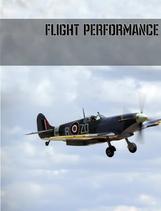
![[Spitfire IX] DCS
EAGLE DYNAMICS 127
Pre-Flight Checks
Ensure the following:
• The stop valve lever must be in the rear (closed) position.
• The undercarriage valve lever must be located in the rear (release) position, while the
emergency release lever must be locked in the upright position.
• the external fuel tank valves must be in the OFF (closed) position.](https://image.slidesharecdn.com/dcsspitfireixflightmanualen-231006033519-04494cd4/85/DCS-Spitfire-IX-Flight-Manual-EN-pdf-127-320.jpg)
![DCS [Spitfire IX]
128 PRE-FLIGHT CHECKS
• the fuel cock handle must be in the off position.
• Ensure that all flight instruments are properly connected (joystick, pedals, etc.) to their
respective functions. Begin with a test of the rudder pedals – look to the tail section of the
aircraft and ensure proper deflection of the rudder to the left and right of the aircraft. Use the
designated keypresses or axes: [Num4] or [Num6] to look backwards, [Z] or [X] (or the
rudder axes) for controlling the rudder. Next, test the function of the flight stick Y axis.
Completely push the stick all the way to the end, then pull in the same manner. Next, check
the ailerons – Observe the right aileron and move the stick left and right. Then do the same
while observing the left aileron.
• Both magneto switches must be in the OFF position](https://image.slidesharecdn.com/dcsspitfireixflightmanualen-231006033519-04494cd4/85/DCS-Spitfire-IX-Flight-Manual-EN-pdf-128-320.jpg)
![[Spitfire IX] DCS
EAGLE DYNAMICS 129
• fuel tank booster valves must be in the OFF position
• air pressure in the pneumatic system according to the three-arrow gauge must display a
pressure of no less than 250lb/in² where a full load displays 300 lb/in².
• Altimeter fixed at 0. To do this, place the cursor over the highlighted regulator and adjust
with the mouse wheel.](https://image.slidesharecdn.com/dcsspitfireixflightmanualen-231006033519-04494cd4/85/DCS-Spitfire-IX-Flight-Manual-EN-pdf-129-320.jpg)
![DCS [Spitfire IX]
130 PRE-FLIGHT CHECKS
• The flaps must be working. Place the flaps lever in the down (deployed) position; to do so,
press [F] or the left mouse button with the cursos on the highlighted lever. Look to the left
and right of the aircraft and ensure that both mechanical indicators located on the aircraft
wings have deployed. Then return the flaps lever to the up (retracted) position and ensure
that the mechanical indicators have returned to their original position.
• Ensure proper operation of the movable part of the canopy – [LCtrl+C] shuts the canopy,
while [LShift+C] opens it. Check whether there is dirt on the Plexiglas, and whether the
emergency release bolts are shut.
• Move the throttle handle forward until the visual warning system located on the motor control
column activates. Press [Num+] or push the throttle forward.
• At the same time, make sure that 1. the undercarriage status light shows a green light and
"DOWN" on the inscription. 2. the fuel pressure warning light is red. Once the warning systems
have been tested, return the throttle to its initial position by pressing [Num-] or by pulling
the throttle.](https://image.slidesharecdn.com/dcsspitfireixflightmanualen-231006033519-04494cd4/85/DCS-Spitfire-IX-Flight-Manual-EN-pdf-130-320.jpg)
![[Spitfire IX] DCS
EAGLE DYNAMICS 131
• Check the quantity of fuel on the tanks. Press the button on the gauge and observe the
arrow. Release the button after checking.
The aircraft is now ready for engine startup.
To startup the engine, perform the following procedures:
• Depress the brakes, so that the aircraft remains in place during engine startup. Place the
mouse cursor over the highlighted section of the control stick and roll the mouse wheel.](https://image.slidesharecdn.com/dcsspitfireixflightmanualen-231006033519-04494cd4/85/DCS-Spitfire-IX-Flight-Manual-EN-pdf-131-320.jpg)
![DCS [Spitfire IX]
132 PRE-FLIGHT CHECKS
• Place the fuel cock handle in the ON position. Left-click on the highlighted handle or press
[T].
• Move the throttle forward by 10-12mm starting from the rearmost position. Press [Num+]
or push the throttle of your joystick system.](https://image.slidesharecdn.com/dcsspitfireixflightmanualen-231006033519-04494cd4/85/DCS-Spitfire-IX-Flight-Manual-EN-pdf-132-320.jpg)
![[Spitfire IX] DCS
EAGLE DYNAMICS 133
• Set the pitch lever to its frontmost position. Press [PageUp] or move the throttle axis.
• Move the dust filter lever to the frontmost position (FILTER IN OPERATION). Press [H] on
the keyboard or click the highlighted lever.](https://image.slidesharecdn.com/dcsspitfireixflightmanualen-231006033519-04494cd4/85/DCS-Spitfire-IX-Flight-Manual-EN-pdf-133-320.jpg)
![DCS [Spitfire IX]
134 PRE-FLIGHT CHECKS
• Turn the handle of the primer pump. Hover your mouse over the highlighted section and roll
the mouse wheel. Then perform the required number of complete movements by the primer
pump in order to fill the engine. To do this, press and hold [Insert] or the left-mouse
button with the cursor on the highlighted section. The following table shows the number of
complete movements to be performed by the piston pump depending on the outside
temperature:
Outside air temperature,
°С
+30° +20° +10 0° -10° ~ - 20°
Number of complete
movements
2 - 3 4 5 5 - 6 Up to 15
• Create fuel pressure using the wobble pump (9-10 pumps) until the warning light begins to
flash. Press [LCtrl+Insert] or click the highlighted section in the cockpit.](https://image.slidesharecdn.com/dcsspitfireixflightmanualen-231006033519-04494cd4/85/DCS-Spitfire-IX-Flight-Manual-EN-pdf-134-320.jpg)
![[Spitfire IX] DCS
EAGLE DYNAMICS 135
• Switch on both magnetos by placing their switches in the ON position. [LShift+End] and
[RShift+End], or click on the highlighted switches in the cockpit.
• Pull back the protective caps on the starter and booster coil buttons by clicking on the
highlighted elements.
• Simultaneously press the starter and booster coils: the keybinds are [Home] and
[Delete] respectively. After the first spark in the motor, move the stop valve lever forward](https://image.slidesharecdn.com/dcsspitfireixflightmanualen-231006033519-04494cd4/85/DCS-Spitfire-IX-Flight-Manual-EN-pdf-135-320.jpg)
![DCS [Spitfire IX]
136 PRE-FLIGHT CHECKS
by pressing [M] on the keyboard or by clicking it with the mouse. Then release the starter
and booster coil buttons.
• If motor startup fails, pull back the stop valve lever and repeat the process beginning from
engine filling.](https://image.slidesharecdn.com/dcsspitfireixflightmanualen-231006033519-04494cd4/85/DCS-Spitfire-IX-Flight-Manual-EN-pdf-136-320.jpg)
![[Spitfire IX] DCS
EAGLE DYNAMICS 137
Enginewarmup
• After successful engine startup, pull back the idle cut.off control to its rearmost position.
• Ensure that the oil pressure is within 60-120ft/in 2
.
• Return the protective caps of the starter and booster coil buttons by clicking on them.](https://image.slidesharecdn.com/dcsspitfireixflightmanualen-231006033519-04494cd4/85/DCS-Spitfire-IX-Flight-Manual-EN-pdf-137-320.jpg)
![DCS [Spitfire IX]
138 PRE-FLIGHT CHECKS
• Turn the handle of the primer pump by highlighting it with the cursor and rolling the
mouse wheel.
• Set the throttle to the position corresponding to 1000-1200 RPM according to the
tachometer.
• Continue to warm the engine at an RPM of 1000-1200 until the oil temperature reaches
20°C and the coolant fluid temperature reaches 60°C (shown by the left and right
instruments respectively)](https://image.slidesharecdn.com/dcsspitfireixflightmanualen-231006033519-04494cd4/85/DCS-Spitfire-IX-Flight-Manual-EN-pdf-138-320.jpg)
![[Spitfire IX] DCS
EAGLE DYNAMICS 139
Engine runup
During engine runup, double check the control instruments, which must show the following figures:
Basic modes of operation of the Merlin 66 engine, with 100 octane fuel
Mode
Basic data
Takeoff Combat Nominal Cruising
I spd. II spd. I spd. II spd. I spd. II spd. I spd. II spd.
Horsepower 1325 -
1680*
1440 1310 1135 985 865
1750**
1630 1410 1315 1095 1030
RPM 3000 - 3000 3000 2850 2850 2650 2650
Boost
lb/in² +12
-
+18 +18 +12 +12 +7 +7
mm Mercury 1350 1690 1690 1380 1380 1120 1120
Altitude limits in m. (w/o
ram air flow)
305 - 1680 4960 2750 5800 3660 6330
Time for uninterrupted
operation, in minutes
5 - 5 5 60 60 Unltd unltd
*- Data for sea level
** - Data on approximate altitudes.
23. Using the throttle lever, set a boost pressure of 4 lb/in² and check the ff.:
1.) Activation of the second speed compressor, for which the compressor speed selector switch
located on the dashboard must be set to "AUTO" (automatic gear shifting,) and click on the
button for testing the activation of the compressor second speed, located on the left side of
the pilot's seat.
The signal lamps on the dashboard serves as confirmation of successful activation of the
compressor second speed.
NOTE. Before activation of second speed, first ensure that the pressure of the pneumatic system has
not fallen bellow 150 lb/in².
1.) Operation of the propeller regulator. To do so, move the pitch lever from its frontmost
position to the rear position, reducing the RPM to 250-300. Afterwards, push the lever to
its frontmost position, which should return the RPM to its full value.](https://image.slidesharecdn.com/dcsspitfireixflightmanualen-231006033519-04494cd4/85/DCS-Spitfire-IX-Flight-Manual-EN-pdf-139-320.jpg)
![DCS [Spitfire IX]
140 PRE-FLIGHT CHECKS
2.) Operation of the automatic temperature regulator for the cooling fluid and oil. To do so,
push the control button of the radiator grates. Opening of the radiator valves tunnels must
be control by the technician located near the aircraft.
3.) Using the throttle, set a pressure of 9lb/in², and by alternately switching off the magnetos ensure
proper operation of the ignition system by checking for a decrease in RPM and by ear. Decrease
in RPM with one working magneto, compared to the RPM when both are active, must not exceed
100RPM.
4.) Check engine response and motor operation on takeoff mode: set the pressure to 12lb/in² over
2-3 seconds using the throttle at an RPM of 3000.
5.) When testing the motor, ensure the ff:
- Completely pull on the stick.
- Hold on to the aircraft’s tail with a weight of about 2 people.
- Do not allow an increase in coolant temperature beyond 120°C and oil temperature beyond
85°C.
- Take note whether the electric generator is working (check the voltometer arrows) and test the
radio equipment for 2-way communication.
Take-Off and climb
Taxiing
1. Prior to taxiing, ensure that all instruments are working and double-check the position of the
levers and handles.
- Coolant temperature between 60° С - 120° С.
- Oil temperature between 20° С - 80° С.
- Pitch lever in the position corresponding to the takeoff mode. (fully up front)
- External tank valves shut off.
- Main fuel tank valves on.
- Undercarriage lever in the DOWN position.
- Pneumatic system air pressure no less than 220 lb/in².
- Weapon safeties engaged.
- Radio systems turned on and tuned into the assigned frequencies.
2. Buckle up!
3. Give the command to remove the wheel pads. Upon receiving confirmation, begin taxiing.
4. Double-check proper brake operation during taxi. Upon completely depressing the brakes and
pulling on the stick, the aircraft must remain in place even with the motor working (with an RPM
up to 1800)
5. For best view of the surrounding area, raise the pilot seat and open the canopy.
NOTE
1. Fast taxiing on uneven terrain is dangerous. Due to the narrow track of the aircraft
undercarriage, when one wheel hits an uneven surface, the aircraft may come into contact
with the ground.
2. Minimize engine work and shorten taxi time when working in hot weather as the engine may
quickly overheat.
3. Taxiing on soft ground without an escort on the tail of the aircraft is prohibited.
4. The stick must be completely pulled back during taxiing.](https://image.slidesharecdn.com/dcsspitfireixflightmanualen-231006033519-04494cd4/85/DCS-Spitfire-IX-Flight-Manual-EN-pdf-140-320.jpg)
![[Spitfire IX] DCS
EAGLE DYNAMICS 141
Before takeoff
1.) Before taking off, once more check if all systems are normal: check instruments and their
readings. Check the position of the following:
i. Elevator trimmers neutral, rudder trimmers 7-8 mm to the right to
counteract the aircraft’s tendency to yaw left.
ii. Main fuel valves in the on position.
iii. External fueltank valves shut off.
iv. Fuel boost valve in the OFF position.
v. Pitch lever fully forward.
vi. Flaps lever in the UP position (retracted)
2.) Apply breaks and increase RPM.
3.) Check for debris on the runway, and check surroundings.
Takeoff
1.) Throttle up until a boost value of 8-12 lb/in² is achieved depending on the aircraft load and
the airfiend condition. Depending on the acceleration, begin to release the stick in order to
raise the tail for takeoff position. Compensate for the aircraft’s tendency to yaw left by
yawing right and try to keep takeoff path as straight as possible.
Liftoff occurs at 90-95mph IAS.
2.) To avoid aircraft ballooning and the consequent loss of speed, do not immediately attempt
a climb after liftoff, but follow the runway just above the ground until an IAS of 140mph is
achieved, after which the pilot may begin to climb and retract the undercarriage.
3.) To raise the undercarriage, first pull back the undercarriage control lever and take it out of
the slot, and then push it into the forward position and press it against the board. Leave
the lever in this position and watch the signal lights. As soon as the undercarriage begins
to retract, the green light goes out and lights up red when the undercarriage is fully
retracted and locked in place. The undercarriage lever shuts off automatically - the lever
drop into the upper groove and the hydraulic valve in the quadrant on the undercarriage
lever will show the position of "IDLE" (neutral). In addition, when retracting the
undercarriage, the pilot will hear the wheels settling in the wings.
If the undercarriage does not retract, repeat the process and holt it in the front position.
Deployed and unlocked landing gears slow down the aircraft and may lead to engine overheat.
NOTE. After retracting the undercarriage, it is necessary to turn out the anti-dust filter.
Climbing
1. To achieve maximum rate of climb, pilots may make use of maximum power (Pk=12 lb/in²,
n=2850 RPM). In extreme situations even combat mode may be used (Pk=18 lb/in², n=3000
RPM), but for no longer than 5 minutes.](https://image.slidesharecdn.com/dcsspitfireixflightmanualen-231006033519-04494cd4/85/DCS-Spitfire-IX-Flight-Manual-EN-pdf-141-320.jpg)
![DCS [Spitfire IX]
142 PRE-FLIGHT CHECKS
2. In all cases where maximum rate of climb is not required, climbing may be performed with a
pressure 7lb/in² and 2650RPM. Doing so conserves fuel and increases total flight range.
3. Refer to the following table for the most efficient speeds for climbing at certain altitudes:
Altitude Speed
From (ft) To (ft) mph
0 12000 185
12000 15000 180
15000 20000 170
20000 25000 160
25000 30000 150
30000 33000 140
33000 37000 130
37000 40000 120
40000 - 110
4. While climbing, ensure that the temperatures for coolant and oil do not exceed 125° and 90° C
respectively.
5. Control of the radiator grates is automatic depending on the coolant temperature. The grates
open at temperatures above 115°C. In case of system failure, the grates may be opened by
pressing the button located on the left side of the pilot seat.
6. Supercharger 2nd
speed engages automatically at 13500-14000 ft while climbing. While
descending, the supercharger returns to 1st
speed past 12500 ft.
7. If it is necessary to use 1st
speed past 13500-14000 ft, set the dashboard switch to MS.
8. Fuel boost valve must be set to off. Switch on only in response to the red light signaling a loss of
fuel pressure (lower than 10lb/in²)
9. Rules for using the fuel tanks:
Startup, motor warmup, takeoff: Use main tanks. Switch fuel feed to use external tanks only at
altitudes above 2000ft (600m) and only when external tanks are in place.
10. Before dropping external tanks that have not been fully exhausted, first connect the main fuel
tanks, then release.
11. If the external tanks have no fuel remaining, or if it has been jettisoned, ensure that the valve for
the external tanks is completely shut off. If they are not completely closed, the system will be fed
air and may lead to interruptions in the motor operation.
12. Periodically check remaining fuel levels while in flight by pushing the fuel gauge button. The
gauge will begin to show remaining levels only after it begins feeding off the lower tank.
Preparing weapons systems for use in flight
13. Remove the weapon safeties by moving it from left to right. A pin will come out of the upper part
of the trigger system that signifies weapons readiness.
14. Regulate the sight glow intensity by using the rheostat located under the gunsight on the
dashboard. The rheostat has three positions – OFF, NIGHT, and DAY.
In-flight radio system testing
15. While in flight, periodically hail the ground stations to check if the radio is working.
16. In case of loss of contace between the ground station, continue to hail and receive until
restoration of communications according to the schedule approved by the chief of
communications.](https://image.slidesharecdn.com/dcsspitfireixflightmanualen-231006033519-04494cd4/85/DCS-Spitfire-IX-Flight-Manual-EN-pdf-142-320.jpg)
![[Spitfire IX] DCS
EAGLE DYNAMICS 143
Level flight
1. Circling flight may be performed at indicated airspeeds no less than 150mph without external
tanks, and no less than 175mph with external tanks.
2. Operational flights, rebasing, patrol flights, loitering at target areas, flights in reserve regiments
(with the exception of aerobatics and air combat training) must be performed under the
economic regimes.
3. When switching flight modes to reduce airspeed, perform these steps in the following order:
- Set the required (reduced) airspeed with the throttle lever.
- Set the specified RPM with the pitch lever.
- If the aircraft experiences a reduction in airspeed, then achieve the required airspeed by means
of the throttle lever.
4. When switching flight modes to increase airspeed, perform these steps in the following order:
- Set the specified RPM with the pitch lever.
- Using the throttle lever, set the boost to the required airspeed. Take care not to exceed the
boost settings conforming to the chosen flight mode.
5. In order to achieve maximum speeds (for use during enemy contact, pursuit, air combat, and
retreat) the motor must be set to operate at the nominal or combat modes of flight (depending
on the circumstances.) To do so, first set the RPM, followed by the boost settings corresponding
to the chosen mode of flight.
NOTE. Motor operation in combat mode is permitted for periods no longer than 5 minutes.
Additionally, the oil and cooling fluid temperatures must not be allowed to exceed limits.
6. The aircraft is easily balanced by trimmers on the entire diapason of horizontal flight. An aircraft
properly configured may be left to fly uninterrupted without pilot intervention.
7. A complete loss of speed during horizontal flight on an aircraft with normal weight and throttled-
down engine will happen under the following conditions:
- when gears and flaps are retracted – at 85mph IAS.
- when gears and flaps are deployed – at 75mph IAS.](https://image.slidesharecdn.com/dcsspitfireixflightmanualen-231006033519-04494cd4/85/DCS-Spitfire-IX-Flight-Manual-EN-pdf-143-320.jpg)
![DCS [Spitfire IX]
144 PRE-FLIGHT CHECKS
Distance and duration of flight under different modes
(without external tanks) Gп=3392 KG, Vгор=392 L.
Flight mode
Altitude IAS
RPM
Fuel
consumption
Until tanks are emptied
ft mph
L/km L/hr
Distance of
horizontal
flight, km
Duration of horizontal
flight, H:MIN
m kph
Distance,
maximum speed
21600 256
2570 0.52 295 595 1:03
6600 410
Distance,
relative
maximum speed 16400 245
2360 0.475 237 685 1:22
5000 394
Maximum
distance
3280 187
1800 0.395 125 880 2:46
1000 300
Weapons control
1. Control of the guns is by means of the pneumatic system and the triggers installed on the
control sticks.
2. Both cannons and machineguns can be fired separately from each other or simultaneously.
Pressing the upper part of the trigger opens fire from the machineguns; the lower part for
cannons; and the middle part for simultaneous fire from both weapon types.
3. Reloading of the weapons systems may be performed only on the ground.
4. Weapons fire must be in short, controlled bursts: 10-15 rounds per burst from the
machineguns, and 3-5 rounds per burst from the cannons.
Emergency canopy jettison
During emergency escape from the aircraft, the canopy may be jettisoned by means of the
emergency jettison lever: pull the rubber balloon located on the upper part of the canopy
frontward and then down, then push the lower part of the canopy with your elbows. In extreme
situations, use the crowbar that is kept on the inner side of the doors.](https://image.slidesharecdn.com/dcsspitfireixflightmanualen-231006033519-04494cd4/85/DCS-Spitfire-IX-Flight-Manual-EN-pdf-144-320.jpg)
![[Spitfire IX] DCS
EAGLE DYNAMICS 145
Flying
1. Aerobatics and stalls may be performed only on an aircraft with no external tanks attached.
2. Before performing aerobatic maneouvers, first balance the aircraft by its trimmers at an
IAS of 200mph.
3. Performing aerobatic maneouvers must be done with smooth movements of the control
platforms. Sharp, sudden movements may lead to excessive Gs and as such are not
permitted.
4. Bankig turns and acceleration upon entering combat, loops, immelmans and hammerheads
may be performed at maximum continuous power (Pk=12 lb/in², n=2850 RPM.) In special
cases, when circumstances demand the absolute maximum capabilities of the aircraft’s
motor, pilots may switch to the motor’s combat mode for periods of no longer than 5
minutes. (Pk=18 lb/in² , n=2850 RPM) During vertical maneouvers, keep in mind that the
airspeed figures indicated on the instruments will give distorted (low) figures.
Banking turns
1. The most advantageous speed for such turns with a bank angle of 65-70° is 185mph IAS
at nominal engine operation. At the same time, the minimum time for a banking turn at an
altitude of 3000 feet is at 17-18 seconds.
2. The plane performs turns steadily and can easily shift from one turn to another. On the
left-hand turn the aircraft has a slight tendency to lower the nose, and vice versa.
3. When you drag the handle to turn, the aircraft will shake a little and start to slide on the
wing. In this case, release the handle slightly: the sliding will stop and the plane will
continue to turn.
Chandelle
1. To perform a chandelle, the motor must be set to maximum continuous power, and
airspeed pushed to its maximum (at altitudes of 21000 feet above ground – 310mph IAS)
after which the control stick must be smoothly pulled back and in the desired direction,](https://image.slidesharecdn.com/dcsspitfireixflightmanualen-231006033519-04494cd4/85/DCS-Spitfire-IX-Flight-Manual-EN-pdf-145-320.jpg)
![DCS [Spitfire IX]
146 PRE-FLIGHT CHECKS
combined with rudder movement in the same direction. This sets the aircraft to climb in an
upward spiral with a roll up to 50°.
2. Complete the maneouver at an IAS of 140-150mph while the motor is running at maximum
power. The aircraft will have gained 1900 feet of altitude.
3. Performing this maneouver with excessive bank will cause the aircraft to quickly lose speed
and gain less altitude from the maneouver.
Split S
1. Split S’ are performed at speeds of 150mph IAS. In 2-3 seconds, smoothly move the stick
in the desired direction at about 3/4s of its maximum reach, and the corresponding rudder
by about 1/2 of its maximum reach.
2. At about 20-30° to aircraft inversion, interrupt the roll by placing both control platforms in
their neutral position.
3. Once the aircraft has stopped rolling, reduce throttle and slightly pull on the stick to
maneouver the aircraft into a dive.
4. After gaining 220-230 mph IAS, smoothly maneouver the aircraft back to horizontal flight.
Take care not to overload the aircraft.
5. If, after the Split S, another vertical maneouver is required, then the acceleration that
takes place while diving must be done at an angle of no more than 40° relative to the
horizon, followed by a gradual decrease in the angle.
6. The aircraft loses 1300-1400 feet after performing this maneouver.](https://image.slidesharecdn.com/dcsspitfireixflightmanualen-231006033519-04494cd4/85/DCS-Spitfire-IX-Flight-Manual-EN-pdf-146-320.jpg)
![[Spitfire IX] DCS
EAGLE DYNAMICS 147
Barrel roll
1. Barrel rolls are performed at speeds of 160-170mph IAS, and the aircraft must be trimmed
for horizontal flight beforehand. The aircraft must have a pitch-up angle of 10-15°; after
ensuring this, smoothly and simultaneously push the stick and rudders by ½ of their
maximum reach in the desired direction. Cease rolling at about 10-20° until the horizontal
position by returning the stick and rudder to their neutral positions. This maneouver,
performed ideally, takes 5-6 seconds.
2. The technique for performing a barrel roll is identical regardless of direction, but barrel
rolling to the right must be done more energetically.
3. Excessive movement of the stick, insignificant pulls upon entry will lead to a significant
increase in roll speed and shaking in the aircraft.
Loop
1. Loops are performed at speeds of 230-240mph IAS. Prior to performing the maneouver,
account for acceleration such that the aircraft reaches the required airspeed prior to
pitching up. Smoothly pull the stick towards you to initiate climbing, and maintain this
position until the aircraft begins to dive at the end of the maneouver.
2. As the aircraft enters the dive, lower throttle and slowly begin to release the control stick in
order to build up acceleration.
3. Upon reaching 220-230 mph IAS, maneouver the aircraft out of the dive.
4. The control stick must be pulled back during the climbing part of the maneouver, otherwise
the aircraft will lose speed and fall on its wing or back. Correct execution yields an altitude
gain of 400-500 feet.](https://image.slidesharecdn.com/dcsspitfireixflightmanualen-231006033519-04494cd4/85/DCS-Spitfire-IX-Flight-Manual-EN-pdf-147-320.jpg)
![DCS [Spitfire IX]
148 PRE-FLIGHT CHECKS
Immelmann
To perform an Immelmann, it is necessary to accelerate the aircraft to a speed of 250-260 mph.
The first half of the Immelman is performed in the same manner as the first half of the loop.
When approaching the apex of the maneouver, when the aircraft is in an inverted position and
the horizon appears in the middle of the glare shield, smoothly push both control surfaces toward
the desired rotation. At 10-15° to the horizontal position, return both stick and rudder to neutral.
Normal speed on exit should be at least 140 mph. The aircraft gains 1700-1800 feet after an
Immelman.
Sideslip
The plane glides steadily with a roll up to 40 ° (with the landing gear and flaps); speed of entry
being 130mph, exit at no less than 120 mph. To exit from sideslip, correct with ailerons and set
the normal glide angle. Maintain flight direction with rudders.](https://image.slidesharecdn.com/dcsspitfireixflightmanualen-231006033519-04494cd4/85/DCS-Spitfire-IX-Flight-Manual-EN-pdf-148-320.jpg)
![[Spitfire IX] DCS
EAGLE DYNAMICS 149
Stalls
Induced tailspins are permitted for training: only up to two turns from a height of no less than
10,000 feet.
To exit a tailspin, push rudder to maximum in the opposite direction of the tailspin while pulling
on the stick.
Once the aircraft ceases to spin, set rudders to neutral, and after gaining an airspeed of 150mph
on a dive maneouver the aircraft back to horizontal flight.
Diving
1. Before entering a dive, first trim the aircraft for horizontal flight at an IAS of 280mph.
2. Diving may be performed from any position with an engine RPM of no more than 2850,
throttle set to no less than 1/3. The values for RPM and boost must not exceed the
maximum permitted values under combat mode.
3. The aircraft descends steadily from any angle.](https://image.slidesharecdn.com/dcsspitfireixflightmanualen-231006033519-04494cd4/85/DCS-Spitfire-IX-Flight-Manual-EN-pdf-149-320.jpg)
![DCS [Spitfire IX]
150 PRE-FLIGHT CHECKS
4. 450mph IAS is the maximum airspeed for diving, while the maximum RPM is 3150 over 20
seconds.
5. Exit the dive by smoothly pulling the stick. Sharp pulls may lead to excessive Gs, which in
turn may cause the pilot to lose consciousness, or even lead to catastrophic damage to the
airframe.
6. The total loss of altitude on a dive is 5000 ft, with a max airspeed of 450mph IAS
Landing
Preparing for landing
1. Engage the safeties for the weapon triggers. Ensure that:
- Pitch lever is set to low pitch. (frontmost position)
- second supercharger speed is off (red light off)
- gauges show an internal pressure of 220 lb/in² in the air system and 800 lb/in² in the brake
system.
2. Open the canopy.
Normal gear deployment
1. Deploy gears at a speed of 150-160mph IAS before the third turn.
Prior to deploying the landing gears:
1) For 2-3 seconds hold the undercarriage lever in its frontmost position to relieve the locks.
2) Sharply pull the lever to its rearmost position and leave it there. The lever will automatically
lock into the gap as the undercarriage locks in place in the deployed position. The hydraulic
valve indicator will once again show IDLE.
3) If there is resistance when attempting to pull the lever backwards, then repeat step 1, but
this time hold the lever for longer (3-5 seconds.) In this case, provide additional relief to the
locks by reducing airspeed to 120-130 mph and lowering the RPM to 1200-1800, or by
briefly and energetically nosing down.
4) Once the green undercarriage signal lights are shown, double-check undercarriage
deployment and locking.](https://image.slidesharecdn.com/dcsspitfireixflightmanualen-231006033519-04494cd4/85/DCS-Spitfire-IX-Flight-Manual-EN-pdf-150-320.jpg)
![[Spitfire IX] DCS
EAGLE DYNAMICS 151
Emergency undercarriage deployment
If the hydraulic system fails after all the steps above have been taken, pilots are authorized touse
the emergency undercarriage deployment system.
- Pull the gear deployment handle down.
- break the seal and place the emergency handle in the frontmost position.
- ensure that the undercarriage has deployed successfully.
Gliding descent
1. Straight gliding descent with retracted undercarriage and flaps is performed at a speed of 100-
120 mph IAS; with deployed gear and flaps, 100-110 mph IAS.
2. Avoid overcooling the engine. On lengthy gliding descents, raise the engine RPM to 2400-2500
for 5-6 seconds every 3-4 minutes.
3. Reliable motor acceleration is guaranteed when the coolant temperature is not lower than 60° C
and oil temperature is not lower than 20° C.
4. Turning before landing approach must be done at a speed of 150mph IAS. (assuming final
approach is started at an altitude of no lower than 500ft)
5. Deploy flaps at a speed no greater than 160mph by pulling the flap deploy handle downwards.
6. Check instruments to ensure that the flaps have indeed deployed successfully.
7. NOTE. In case of pneumatic system malfunction and a loss of pressure (below 120 lb/in²),
perform the landing with retracted flaps, setting aside compressed air for the brakes.
8. After flaps deployment, smoothly pull the stick to reduce speed to 100-110 mph IAS, which is the
normal gliding speed.
Go-around
If forced to go-around:
- Smoothly push throttle to maximum.
- retract the undercarriage (flying with a deployed undercarriage can cause an overheat of the
coolant) and begin a climb.
- at an altitude of no lower than 300 ft and at a speed of 130mph IAS: retract flaps.
Landing
1. When landing with deployed flaps, flare at an altitude of 6-7 meters; when flaps are retracted,
this must be done at 5-6 meters. Complete touchdown at 0.25m-0.5m.
2. For touchdown on all three points, do not completely pull back on the stick.
3. After touchdown, periodically depress the brake trigger. Avoid braking sharply when the aircraft
may potentially nose over – begin braking only when the stick is fully pulled back.
4. After your ground speed is under control, retract the flaps by returning the handle to the UP
position.
5. Observe the runway and proceed to taxiing.
After taxiing
1. Cool the engine by letting it run for 2-3 minutes at an RPM of 800-1000.
2. Stop the motor by pulling the shutdown lever from its frontmost position all the way back to the
slot, then smoothly push the throttle forward.
3. After motor shutdown, shutoff ignition and close the fuel valve.
4. Shutoff all electrical systems.
After flight
Inform the mechanic of any in-flight issues with the aircraft that need resolving.](https://image.slidesharecdn.com/dcsspitfireixflightmanualen-231006033519-04494cd4/85/DCS-Spitfire-IX-Flight-Manual-EN-pdf-151-320.jpg)
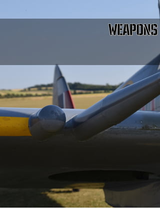
![[Spitfire IX] DCS
EAGLE DYNAMICS 153
Armament
The plane is armed with machine-guns and cannons and also has the ability to carry three bombs on
three hardpoints – one on the center-line and one beneath each wing.
Cannons
The aircraft’s cannon-type armament consists of two 20-mm Hispano Mk. II guns, each with an
ammuniton capacity of 120 rounds. The cannons are supplemented with four additional .303 calibre
(7.69mm) Browning machineguns, with an individual ammunition capacity of 350 rounds.
These guns are mounted in the aircraft’s wings on special mounts.
Trajectory calculation is performed with the help of the reflector sight mounted in on a bracket above
the instrument panel. Weapons fire is controlled by a pneumatic valve controlled by a button
mounted on the aircraft control stick.
Compressed air enters the air system of the cylinder that is charged during operation of the motor
compressor. Fire management is carried out by means of the trigger.
1. Depressing the upper part of the trigger fires the machine guns.
2. Depressing the lower part of the trigger fires the cannons.
3. Depressing the middle part of the trigger discharges both weapons at once.
There is a lever located below the trigger. When turned to the left, the trigger safety mechanism is
engaged; when turned to the right, the safety is disengaged.
Reloading the guns is performed only on the ground. The cannons have a pneumatic reloading
system, while the machineguns are loaded by means of a special cable.
Pneumatically loading the cannons is by means of a special valve, installed in the gun compartments,
located at the rear-right section for the left plane, and rear-left for the right plane.
In order to reload the right plane cannon, the valve lever must be depressed, while the left plane
lever must be pulled upwards. The pneumatic loading system is powered by a special tank with a
pressure of 250-300 lb/in²
Before takeoff, cuts in the skin under the guns must always be sealed with fabric lining. The cannon
barrels also must be covered (when on the ground.)](https://image.slidesharecdn.com/dcsspitfireixflightmanualen-231006033519-04494cd4/85/DCS-Spitfire-IX-Flight-Manual-EN-pdf-153-320.jpg)
![DCS [Spitfire IX]
154 ARMAMENT
Figure 86: 303in and 20mm Gun Installation
“HISPANO” Mk. II Gun
Development History
The UK, on the eve of World War II, saw the beginning of a program for the development of cannon-
armed fighter aircraft, and license was acquired for the manufacturing of French HS.404 guns. This
choice (which proved to be in the French weaponsmiths' favour) was not made immediately: the
possibilty of acquiring a license for the Swiss Oerlikon guns was considered at first. In 1936, a
demonstration of a working prototype of the HS.404 was set up in Paris. The demonstrations proved
the superiority of the French weapon over the Oerlikon: while the dimensions and weight were
similar, the French cannon proved to be capable of faster and more destructive fire. As a result, the
French gun was adopted by the Royal Air Force under the designation Hispano Mk.I. Nevertheless, it
took a considerable amount of time to acquire permission for purchasing the license, to settle all the
necessary formalities, to setup the Hispano company branch in Gratham (the British Manufacturing
And Research Company - BMARCO), to translate all the drawings from millimeters to inches, to setup
production facilities, to test and fine-tune gun prototypes, and then to eliminate all the difficulties
associated with the installation of the guns in aircraft wings.](https://image.slidesharecdn.com/dcsspitfireixflightmanualen-231006033519-04494cd4/85/DCS-Spitfire-IX-Flight-Manual-EN-pdf-154-320.jpg)
![[Spitfire IX] DCS
EAGLE DYNAMICS 155
Figure 87: HS.404 cannon with 60-round drum magazine
For this reason, the Hispano guns were not able to play a significant role in the Battle of Britain. Only
in 1940 did the British begin to install Hispano cannons on their aircraft - first on their Westland
Whirlwind heavy fighters, and later on the Bristol Type 156 Beaufighters (sometimes referred to
simply as "Bo"). Thus, Royal Air Force planes found a new, powerful cannon armament at their
disposal.
Meanwhile, during the Battle of Britain, it became apparent that batteries of 8 rifle-calibre guns - the
traditional armament of fighter aircraft at the time - was completely inadequate, and the main
weapon on fighters should be automatic cannons.
Air-to-air combat experience on Beaufighters, which were used in part as night fighters, once again
stressed the need for a belt-feed mechanism for automatic cannons. On such fighters, the task of
reloading the cannons was delegated to the radar operator, and under conditions of total darkness
while in a maneouvering aircraft, one had to change heavy 60-round drum magazines relying on
practically nothing more than touchTrial attempts were made at installing cannons in the wings of
Hurricane and Spitfire fighters, which resulted in several new problems: when performing energetic
maneuvers the cannons tended to jam, and worked very unreliably in general. June 1940 saw the
participation of the first (and only) squadron, the 19th squadron, flying cannon-equipped Spitfire
Mk.IB aircraft. Each plane carried a pair of Hispano Mk.I cannons. The results of this proved to be
truly catastrophic - the cannons jammed with such frequency, and oftentimes after the very first
shot, that the pilots immediately demanded that their aircraft be replaced with the usual
machinegun-equipped models.
The issue stems from the fact that the cannons were initially designed for installation on the engine -
fixed to a massive, strong and rigid cylinder crankcase. To even dream of such stability from wing
mounts would have been practically impossible. In addition, the guns had to be installed side-by-side
in order to make room for the drum magazines inside of the wings, which proved to be yet another
reason for failure. Achieving failproof performance of the guns required significant time investment
for ironing out these issues, and consequently, the top brass of the British air force began to doubt
the feasibility of cannons on fighter aircraft, while the war ministry released specifications for the
development of new fighter aircraft equipped with 12 machine guns.
However, the gun design was quickly finalized and the belt-feed mechanism developed by Martin-
Backer was implemented into the design. The modified gun came into service, seeing use on aircraft
of the Royal Air Force and Navy from 1941 onwards under the designation Hispano Mk.II. Instead of
8 Browning machine guns, 4 such cannons were mounted on Hurricane fighters and on some](https://image.slidesharecdn.com/dcsspitfireixflightmanualen-231006033519-04494cd4/85/DCS-Spitfire-IX-Flight-Manual-EN-pdf-155-320.jpg)
![DCS [Spitfire IX]
156 ARMAMENT
modifications of the Spitfire that were designed mainly for tropical and hot climates. Most Spitfire
aircraft only saw 2 cannons alongside 4 rifle-caliber machine guns or 2 heavy machineguns.
Figure 88: Belt-fed Hispano Mk.II cannon
The ammunition also needed improvements. The fuse of standard high-explosive shells proved to be too sensitive, which meant that they would far too
often detonate upon contact with the target aircraft's armor plating, and not in the more vulnerable elements of the airframe, which would have been
more desirable. Tests showed that in many cases the full-metal shells which had no explosive charge dealt significantly more damage onto enemy aircraft.
In 1941, the new high-explosive shells with a delayed-action fuse were created, as well as high-explosive-incendiary projectiles. Full-metal rounds were
also used along the HE shells until the development of new armor-piercing incendiary rounds. These new rounds were composed of a body of high-
explosive shells filled with an SR379 incendiary component (the composition of which was: aluminum-magnesium alloy - 47% barium nitrate - 50%,
paraffin - 3%), but had no fuse - only a full-metal tip. Starting from 1942 the standard combat loadout for Hispano guns consisted equally of HE and
incendiary AP shells, alternating 2 after 2 or 1 after 1.
Description
The automatic cannon operates under a mixed-type system.
The pressure of powder gases discharged through the hole in the barrel to the piston rod provides the force for unlocking the gate after the shot is
fired. The shutter dropping to the rear position is due to pressurized gas to the bottom of the sleeve, like a weapon with blowback. Because of this
principle of automation it is not possible to equip the gun with a synchronizer for firing through the propeller.
Cannon Specifications
1. Caliber .... 20 mm.
2. Total length… 2565 mm (with recoil reducer), 2413.4 mm (with flash hider)
3. Barrel length … 1708 mm.
4. Gun weight, with front-mount unit… 53.75 kg.
5. Ammunition capacity … 20х110, practice shells, HE, HE-Incendiary, AP Incendiary.
6. Individual shell weight … 0.255 kg.
7. Rate of Fire … 570 - 620 RPM.
8. Muzzle velocity … 853.4 m/s.
9. Rifling grooves… 9.](https://image.slidesharecdn.com/dcsspitfireixflightmanualen-231006033519-04494cd4/85/DCS-Spitfire-IX-Flight-Manual-EN-pdf-156-320.jpg)
![[Spitfire IX] DCS
EAGLE DYNAMICS 157
The cannons are installed in the wing compartment between the 8th and 9th ribs. The front mount is
made on the front edge of the wing and consists of two eccentrics with the help of which gun
convergence is regulated. The rear mount allows the gun to take any position, set by the front mount
during zeroing. To ensure that the feeder mechanism remains fixed in place during weapon fire, a
rod is mounted between the spar and the ammo drum.
The cannon is belt-fed, with the ammo belts coming from a box.
The ammunition compartments are located between ribs 10 and 13 behind the main spar. The
compartment can hold 120 rounds; the bottom panel and the top hinged cover are made of a
duralumin sheet with a thickness of 10 S.W.G (3.251 mm.). The front wall has a thickness of 6 mm to
shield the ammunition. Structurally there are 2 compartments in the detachable part of the wing, but
only the frontal compartment is used for housing ammunition. Spent casings are ejected through slits
in the skin of the lower surface.
Ammunition
The cartridge consists of a fuse, projectile, powder charge, the casing and the capsule. For a more
durable connection of the projectile with the shell casing, the casing neck is rolled after the shell is
inserted. It is also for this purpose that there exists a groove on the belt part of the round. The
casing without a flange, extruded with a hole in the bottom under the capsule installation. After
installation, the capsule is fixed in place by annular punching. At the capsule joint and the bottom of
the shell casing is a purple varnish. On the body of the round is a lead belt made of copper. №253
instant action fuses are present on all rounds, save for the armor piercing rounds (which have steel
tips) and practice rounds. Oerlikon type modified fuses (№254 Mark IV) are approved for use as an
alternative.
The powder charge used is pyroxylin gunpowder. Tetryl serves as the explosive material for the
corresponding ammunition types.
The following ammunition types saw production for the Hispano gun:
Ball - Practice shell. It is a hollow shell, the bottom of which is closed off by a disc to prevent the
penetration of gas in the shell. Painted in black or blue.
Tracer - Tracer round. The body of the shell is fused with a burning composition, which is ignited by
the propellant gases. Burning time - 3.5 seconds. Painted black and is marked with the letter T in
red, or by a red stripe on the head.
A.P. - armor-piercing, used against armored targets and aircraft armor. The shell has no inner
content, its sharp tip has a plastic cap. Later modifications of the projectile without the cap and
possess inert gear or armor-piercing core. Painted in black, with the nose of the projectile in white.
A.P./Т (Day/Night) - armor-piercing tracer day / night. Made of armor-piercing steel, without a
plastic cap and laced with tracer content for day or night use. Painted in black, with the tip of the
projectile in white; the leading belt has a white or green band.
H.E.I. - the projectile contains a cartridge of incendiary substances and a cartridge of explosive
material. Both are separated by a seal of waxed cloth. Upon impact, the fuse triggers the explosive
component, which triggers the incendiary component providing high enough temperatures for
igniting fuel. The lower part of the projectile is colored in red, the upper part in dark yellow. Fuse tip
is green.
S.A.P/I – Semi-armor-piercing incendiary shell. This ammunition type is designed for penetrating
armored fuel tanks of target aircraft. The body shell is similar projectile H.E.I. with the cartridge of
incendiary material or explosive cartridge and fuse, and a steel projectile nose. Painted in red, the](https://image.slidesharecdn.com/dcsspitfireixflightmanualen-231006033519-04494cd4/85/DCS-Spitfire-IX-Flight-Manual-EN-pdf-157-320.jpg)
![DCS [Spitfire IX]
158 ARMAMENT
head of the projectile is painted in white. Penetrative properties of the projectile are inferior to
armor-piercing (A.P.) rounds.
Figure 89: Ammunition types
High-explosive, incendiary projectile (H.E.I).
Designed to destroy targets by means of fragmentation and explosive force, as well as to ignite
gasoline in unarmored fuel tanks. The shell is equipped with a direct action fuse head, which
detonates the shell upon impact with even the thinnest obstacle (such as aircraft skin) and at a
distance of no more than 10 cm beyond a barrier. Detonation inflicts a ragged hole in the second,
and sometimes in the first barrier with a diameter of 40 cm, greatly amplifying the fragmentation
effect.
In addition to its strong fragmentation and explosive action, the round is also designed to ignite
petrol in fuel tanks. The shell contains 7 grams of tetryl and 4.3 grams of the S.R.379 incendiary
compound.
Semi-armor piercing Incendiary (S.A.P/I).](https://image.slidesharecdn.com/dcsspitfireixflightmanualen-231006033519-04494cd4/85/DCS-Spitfire-IX-Flight-Manual-EN-pdf-158-320.jpg)
![[Spitfire IX] DCS
EAGLE DYNAMICS 159
Intended for use against aircraft, lightly armored and other such targets where an incendiary effect is
desirable. High-explosive incendiary shells are used in tandem in order to amplify the effects of this
ammo type.
Three versions of this ammunition were produced, Mk.1Z, Mk.2Z and Mk.3Z. The construction of
these shells are identical, with the exception of the detonators, which are designed to ignite the
incendiary component.
Mk.1Z and Mk.2Z rounds weigh 266 g.
Mk.3Z ammunition weighs about 265 grams and has a standard sleeve and shell. The projectile is a
steel hull, the nose section of which has an internal groove for the steel tip. Before installing the tip,
R.D.1248 adhesive or R.D.1229 sealant is applied on the groove and the adjacent surfaces. The tip is
fixed in place by center-punching after the projectile assembly. The bottom of the shell is welded to
the body. The interior of the shell is filled with incendiary composition and the plastic housing of the
detonator. 2 discs, one made of tinned brass and the other of cloth, are located between the
detonator and the tip. A ZY detonator is installed in the shell, weighing approximately 0.39 grams.
This detonator is similar to the one installed in the fuse head of the D.A. №917 Mk.1.
The round's incendiary composition is comprised of three cartidges of the incendiary compound
S.R.379, each weighing about 3 grams, separated from the detonator by a paper disc.
В All three versions are capable of piercing armor plates with a thickness of 20 mm at a distance of
200 meters at an angle of 90 °, while igniting the petrol located behind the armor.
“COLT BROWNING” Machine gun
Development History
By the mid-30s, the RAF leadership suddenly realized that in the realm of aircraft-mounted small
arms English technology was hopelessly behind the rest of the major powers. Unsusprisingly, thus
began a panicked search for an adequate replacement for the machinegun stock left over from the
10-20-ies.
Figure 90: “Browning 0.303” Mark II” Machineguns
The mid-20s saw the first shipments of the new American-designed Browning M1919 machineguns.
The efforts of the American engineers are deserving of praise; hoping to reach the British market, the](https://image.slidesharecdn.com/dcsspitfireixflightmanualen-231006033519-04494cd4/85/DCS-Spitfire-IX-Flight-Manual-EN-pdf-159-320.jpg)
![DCS [Spitfire IX]
160 ARMAMENT
Colt designers, with great difficulty, were able to adapt their machine gun design to the English .303
round. The issue was that the regular rimless American .30-06 Springfield munition differed too
greatly from the English rimmed cartridge, and a thorough rework of the extractor was required in
order to ensure the safe disposal of empty cartridges from the chamber. During the process of this
adaptation in 1925, Armstrong Whitworth & Co. Ltd. purchased six guns for prototype evaluation.
Slow tests of the Browning M1919 were held in England until 1931. When the news came from the
United States about the completion of an improved aircraft version of the .30 Browning M2-AN, an
additional four units were purchased immediately and arrived just in time.
In 1934, Great Britain held competitive testing of the new prototyes for aircraft machineguns, with
the main contenders being the Browning .30 M2 AN, M1919, the English Vickers-J (Vickers Central
Action) - the last of the Vickers machinegun family, with technical information being difficult to come
by, as the only known fact about it was that its maximum rate of fire could reach 1250RPM. Also
participating were the French Darne, Dutch Madsen and Hungarian Gebauer Motorgeppuska
1926/31.Minta GKM machineguns. The Hungarian Gebauer was deemed to be too complex
technologically despite its superior 2000RPM, and the French Darne was deemed too unreliable. The
technical characteristics of the Vickers-J failed to make any impression on the testers. The Dutch
Madsen was also rejected, as it was deemed too costly to produce.
2 models made it to the final stages: the American Browning M2 AN and the Vickers-K. The .30
caliber Browning M2 AN light machine gun saw significant modifications to the original prototype, the
M1919 HMG, which was meant for infantry use. Not only was the calibre changed from 7.62mm to
the English .303, but the gun also saw significant modifications to its automatic fire mechanism. The
testing process showed that the British-made cartridges equipped with cordite striking a heated
chamber after a continuous burst of 100 shots had a tendency to spontaneously ignite. It was an
unpleasant side-effect of all automatic firing mechanisms operating on the basis of the locked breech
system: that is, when in between bursts, the next cartridge loads into the chamber and locked the
breechBut in the case of American cartridges that used powdered pyroxylin (less sensitive to heat,)
spontaneous ignition was a rare occurence. When using the same principle of an open breech, the
round enters the chamber only upon depressing the trigger. Because of the British-made cartriges,
the gun had to be readapted for operation under the open breech system. At the same time, due the
introduction of a delayed impact mechanism into construction, designers managed to retain the
machine gun's ability for synchronized fire, which has always been a problem with open breech
systems. However, despite all efforts, Browning managed to finish its English version only in 1939.
Nevertheless, spontaneous ignition remained a frequent occurrence when using incendiary
ammunitions with the reworked gun.
History of the .303 cartridge
The history of this famous round, officially entered into active service in 20 February of 1889, began
when the English army adopted the Lee-Metford rifle in 1888. The prototype for this round was the
7.5mm Swedish "Schmidt-Rubin" with a protruding rim.
The cartridge was widespread in Canada and other parts of the British Empire. Though the army
planned to replace it with a more modern round in 1908, it remained in service in the UK until 1957,
when it was replaced by the 7.62x51mm NATO cartridge.
The cartridge was equipped with a smoked powder until 1892, and until 1902, the cartridge had a
bullet with a spherical apex, and a copper-nickel alloy sheath.
The 1st Hague Conference in 1899 saw the adoption of the "Declaration concerning expanding
bullets," resulting in bullets being designed with pointed tips and full-metal jackets - the so-called
Spitzer type.](https://image.slidesharecdn.com/dcsspitfireixflightmanualen-231006033519-04494cd4/85/DCS-Spitfire-IX-Flight-Manual-EN-pdf-160-320.jpg)
![[Spitfire IX] DCS
EAGLE DYNAMICS 161
In 1910, the spherical bullets were finally replaced by Spitzer types; the coating material was also
changed, with steel coated with red brass being used in production. The cartridge was manufactured
in many countries and is still widely used in hunting.
During the First World War, British factories alone produced 7,000,000,000 .303 rounds.
In addition to colour-coding, model numbers/codes were also engraved on the bottom of the shell
casng. All bullets of classifications I to VI had a spherical apex: they are extremely rare and are not
provided in the table. Type II, III, IV and V bullets belong to the expanding munitions type, and were
developed by English army captain Berie Clay (who served in India in the Dumdum Arsenal.)
Type VII bullets were basic to use. The relatively low weight of these bullets despite their significant
length was achieved by using a core of aluminum or bakelite in the bullet tip, with the remaining
parts filled with lead. This design better stabilizes the bullet in flight and amplifies the tumbling effect
upon striking the target, maximizing stopping power. The bullet had a nominal muzzle velocity of
2,440 feet per second (743.7 m/s) and the rotation velocity was about 175 800 rpm. Flight speed and
rotation speed significantly decreased, but even past 800 meters the bullet speed remained
supersonic. Bullets flying past could be clearly heard.
At ranges over 300 yards (274.3 meters) the trajectory of tracer rounds differed significantly from the
trajectory of heavy rounds - it rapidly lost altitude. Due to this, pilots who would correct their fire
based on the tracers would often miss.
The deficit of special munitions led to the widespread use of conventional ammunition. Machineguns
were loaded with belts filled with conventional, armor-piercing, incendiary, tracer and incendiary
ammunition. until the production of special cartridges sped up. By 1942 standard loadouts were
already equipped with armor-piercing and incendiary (B Mk.VI) cartridges. The cartridges in the belt
were usually of the same type. To remind the pilot of depleting ammunition, 5 tracer rounds were
placed before the last 50 rounds.
A one-second volley of 4 machine guns had a burst mass of 900 grams at a rate of 20 rounds per
second and muzzle velocity of about 740 m/s. The guns had ammunition enough for 13 seconds of
continuous fire.
During the Royal Air Force' testing of armor piercing .303 and 7.92mm (German) rounds, it was
discovered that both ammunition types had similar problems with penetration. The tests were carried
out on the rear section fuselage of a Blenhein bomber at a distance of 200 yards (180 meters.) The
armor protection of the rear gunner was a steel sheet with 4 mm thickness. The plate was at an
angle of 60° to the line of fire. The results were disappointing. Only 33% of the discharged bullets
managed to reach the armor plates, the other bullets were scattered or even got stuck in the design
elements. Only 6% of the bullets pierced the armor. Incidentally, the results of the German munitions
were much worse, placing at 23% and 1% respectively.
The characteristics of the incendiary ammunition are also not much different. Test fire against the
sealed fuel tanks of a Blenheim bomber at a distance of 200 yards (180 meters) from behind showed
that the ignition capabilities of the Buckingham B Mk.IV incendiary tracer cartridge were equal
between both types of ammunition. The tank was ignited by one of the 10 hits.
The B. Mk VI De Wilde Incendiary cartridge (which was named after a Belgian inventor, but was in
fact completely redesigned by Major C. Aubrey Dixon), which contained 0.5 grams of the incendiary
composition SR365 (containing a mixture of barium nitrate, which was ignited on target impact)
proved to be twice as effective, requiring only one hit out of five to ignite fuel.](https://image.slidesharecdn.com/dcsspitfireixflightmanualen-231006033519-04494cd4/85/DCS-Spitfire-IX-Flight-Manual-EN-pdf-161-320.jpg)
![DCS [Spitfire IX]
162 ARMAMENT
Figure 91: B. Mk VI “De Wilde” Incendiary Round
Production of the De Wilde rounds began in June 1940 and saw field testing during the evacuation of
Dunkirk. Pilots liked the increased potency of the rounds, coupled with visual confirmation of hits on
target.
Description
The machine gun's operation is based on the principle of using the recoil with short barrel movements. Each instance of recoil moves the barrel
backwards by a short distance. This movement unlocks the gate, knocking it backwards, while the return spring pushes it back. During this backward
movement the breech extracts the spent case from the chamber as well the next the next cartridge from the belt. Then, the spring pushes the breech and
barrel back into position, chambering the next round, locking the barrel and readying the gun for the next shot.
Technical characteristics.
1. Caliber .... 0.303 inches.
2. Total length … 3 ft 8.5 in (1130 mm) (with flash hider)
3. Barrel length … 2 ft. (609.6 mm).
4. Weight … 21 lb 14 oz (9.922 kg).
5. Ammunition … All types: Mk. VII S.A.A.
6. Cartridge weight … 22.9 ~ 25.45g.
7. Loading mechanism … Belt-fed.
8. Rate of fire… 1150 RPM.
9. Muzzle velocity … 743.7 m/s.
10. Barrel grooves… 5.
11. Ammo capacity … 250 rounds per gun.
The machine guns are mounted in the wing compartments between ribs 13 and 14, 16 and 17
respectively.
Gun mounts allow for adjustments to the vertical and horizontal convergence.
The guns are belt-fed, with the belt coming from a box. The boxes are installed in bays between the
14th and 16th ribs. The front compartment houses the ammo box for the internal gun, while the rear
houses the ammo of the outer gun. Access to the compartments is by an easily removable hatch on
the lower surface of the wing.
Spent belts and cartridge cases are ejected through slits in the skin of the lower surface.
Ammo Types
0.303 Ball Mk. VII - cartridge with a heavy bullet. Bullet consists of a steel plated nickel silver shell
and core (core nose of aluminum, the rest of the lead). Brass sleeve. The primer consists of a red-
brass cap, percussion composition and a foil coating with lacquer. The projectile is secured to the
casing by circular-punching. Primer composed of nitroglycerin-based tubular non-graphite
gunpowder. Used against enemy infantry and aircraft.](https://image.slidesharecdn.com/dcsspitfireixflightmanualen-231006033519-04494cd4/85/DCS-Spitfire-IX-Flight-Manual-EN-pdf-162-320.jpg)
![[Spitfire IX] DCS
EAGLE DYNAMICS 163
0.303 Armor Piercing W Mk. VII - cartridge with armor-piercing bullet. Bullet consists of a steel
plated nickel silver sheath and a lead jacket and armor-piercing steel core. Brass sleeve. The primer
composition with a percussion compotion of mercury fulminate and potassium chlorate. Propellant
composed of nitroglycerin plate powder. Used against lightly armored vehicles, armored cars, trains,
etc.
0.303 Tracer G Mk. I - cartridge with a tracer round. Bullet consists of a steel plated nickel silver
shell red-brass cup with tracer composition of white fire and lead core. Brass sleeve. The primer
consists of a red-brass cap, percussion composition, foil coating, lacquered outside. It is secured in
the case by circular punching. The propellant is tubular nitroglycerin powder (cordite).
Used for fire correction. In daytime, the tracer is visible only as a small bright spot from the bottom
of the bullet.
0.303 Incendiary B Mk. IV - cartridge with an incendiary (phosphorous) round. The bullet is
composed of nickel silver plated steel shell with an opening on the pointed end, filled with quick-
melting alloy, cupronickel cylinder with a lead core and grooves on the surface for the passage of
phosphorus that fills the tip of the bullet. Brass casing. The primer consists of a red-brass cap,
percussion composition, foil coating, lacquered outside. It is secured to the casing by circular
punching. Propellant - smokeless pyroxylin coated plate powder.
Used to ignite flammable materials and parts such as fuel tanks, etc.
Figure 92: .303 rounds, cross section
These cartridges were improved throughout the war and saw a few modifications. The very last
modification of the G Mk VIII tracer cartridge was put into service in 1945; of the W Mk 1Z armor-
piercing rounds in 1945; and the B Mk VII incendiary rounds in 1942.
General Characteristics
Total length – 76.7mm
Casing length – 56.1mm
Bullet diameter – 7.9mm
Diameter from cartridge neck – 8.54 mm
Heavy bullet Mk.VII
Armor-piercing W Mk.VII
Tracer bullet G Mk.I](https://image.slidesharecdn.com/dcsspitfireixflightmanualen-231006033519-04494cd4/85/DCS-Spitfire-IX-Flight-Manual-EN-pdf-163-320.jpg)
![DCS [Spitfire IX]
164 ARMAMENT
Case diameter, from rim – 11.65 mm
Rim diameter – 13.44 mm
Bullet weight - 11.13 g onwards
Cartridge weight – 22.9 ~ 25.45 g.
Muzzle velocity - approx.743.7 m/s
Cartridge colour coding
Bullet model
Bottom
Markings
Capsule
Colour
Notes
Marк VII (Z) VII Violet 1910 onwards
Mark VIII Z -- Violet For machineguns
G Mark I (Z) G Red Tracer, 500m
PG Mark I (Z) PGI -- For training use. Cyan paint on base
G Mark II G Red Tracer, 900m
G Mark III G Red Tracer, 750m. Naval use
G Mark IV (Z) G Red Daytime tracer, 500m. Airforce use.
White tip.
G Mark V (Z) G Red Night tracer, 500m. Airforce use. White
tip.
G Mark VI (VII,
VIII) (Z)
G Red Similar to the G Mark II, used together
with the G Mark IV. Tracer, 500m.
W Mark I (Z) W Green Armor piercing, green tip
B Mark III B Blue Dull-tipped incendiary round,
Buckingham type
B Mark IV(Z) -- -- Staged incendiary ammunition for use
against observation balloons
B Mark VI -- -- Incendiary ammunition, steel ball on tip,
threaded plug on base
B Mark VII (Z) -- -- Incendiary, narrowed to the base
O Mark I (II) О Black For target designation. Black tip
O Mark III О Black Same as above. Bullet charged from
base(?)
The letter Z in cartridge designations indicate that smokeless pyroxyle graphite plate-powder is used
instead of cordite.](https://image.slidesharecdn.com/dcsspitfireixflightmanualen-231006033519-04494cd4/85/DCS-Spitfire-IX-Flight-Manual-EN-pdf-164-320.jpg)
![[Spitfire IX] DCS
EAGLE DYNAMICS 165
Figure 93: Cordite strands..
Weapons heating
Often, on early versions of aircraft, weapons malfunctioned due to frozen lubricant on the moving
parts. To ensure trouble-free operation of weapons, aircraft began to use heating systems for their
weaponry. Hot air for heating is taken past the cooling radiators is sent to the machine-gun
compartments by pipelines. The heating system is automated and requires no input from the pilot.
Figure 94: Weapons heating system](https://image.slidesharecdn.com/dcsspitfireixflightmanualen-231006033519-04494cd4/85/DCS-Spitfire-IX-Flight-Manual-EN-pdf-165-320.jpg)
![DCS [Spitfire IX]
166 ARMAMENT
Bombs
Some aircraft were modified to be able to mount bombs under the detachable wing sections between
ribs 8 and 10. Each hardpoint is fastened to the 9th rib into two nodes using the quick-removable
points. Front mount of the hardpoint was located behind the main spar cap, with the rear unit at a
distance of 9 inches from the frontal one. On the left side of the cockpit by the 10th bulkhead are the
fuse control units. On the cockpit left side by the 10th partition is the control set for the bomb fuses.
Bomb release is performed by means of a button at the end of the throttle grip. There is also a
mechanical release on the left side of the throttle.
Aiming
Gunsight – General Characteristics
A Mk.II (8B / 2361) aircraft collimator sight is installed on the dashboard of the aircraft. It consists of
two parts:
- Optical viewfinder (collimator)
- rangefinder
The optical system consists of the reticle, a lens, a reflector,
and a light filter. The reticle has a ring, as well as a point at
the center of two short vertical and two long horizontal
strokes. The reticle is etched on an opaque plane-layer
lens. The bottom of the reticle is illuminated by an electric
lightbulb. The rays pass through the lens reticle and fall on
the reflector glass, which is installed at an angle of 45 ° to
the optical axis of the system. The reflector reflects the rays
from the light source at an angle of 90 ° in the direction of
the observer, who sees the image of the glowing reticle as
if it was focused at infinity.
The gunsight rangefinder consists of two cams, the
horizontal lines of the reticle, two scales and two
handwheels.
The rangefinder mechanism provides a change in the
interval between the visible image of the horizontal lines of
the gunsight reticle. This interval is variable and is the basis
for measuring the distance to the target. The value of the
interval between the lines of the visible image of the sight
grid depends on the angle of rotation of the range
handwheel (upper) and from the target base handwheel
(lower). Rotate the upper handwheel manipulates the upper
scale, called the range scale, while the lower hand manipulates the lower scale, called the base scale
(target size). The range scale is calibrated in hundreds of yards, and the base scale - in feet.](https://image.slidesharecdn.com/dcsspitfireixflightmanualen-231006033519-04494cd4/85/DCS-Spitfire-IX-Flight-Manual-EN-pdf-166-320.jpg)
![[Spitfire IX] DCS
EAGLE DYNAMICS 167
Range scale
In hundreds of
yards
1 2 3 4 5 6
Yards 100 200 300 400 500 600
Meters 91,4 182,8 274,2 365,6 457 548,4
Base scale
Feet 40 50 60 70 80 90 100
Meters 12,2 15,2 18,3 21,3 24,4 27,4 30,5
Gunsight – Specifications
1. Reticle ring diameter – angular values:
- In degrees 6° 44’
- In thousandths 118
2. Reticle rings radius - angular values:
- In degrees 3° 22’
- In thousandths 59
3. When shooting, this ring corresponds for allowance at an aspect of 2/4 and target speed of
322 km/h.
4. At target aspect of ¼, target speed should be 644 km/h
Aiming method adopted by the Air Force in England
In the RAF, lead angle is determined by the magnitude of the angular velocity of the target relative to
the aircraft that is opening fire. This speed is sometimes called the transverse velocity.
Acquisition of such a firing solution requires the pilot to determine the target lateral speed by eye. By
using the reticle ring as a yardstick, the shooter may take into account the relative lead angle at any
transverse speed of the target. Thus it is necessary to know the aspect and direction of the target's
relative increase. We must remember that, taking into account the English target leading technique,
the target relative direction line should be passing through the reticle center, and not the
continuation of the longitudinal axis of the aircraft.
Aiming method adopted by the USSR Red Air Force
The Mk.II sight has one ring with a radius of 59 thousandths. Soviet Air Force sights have 2 rings:
- large, with a radius of 105 thousandths
- small, with a radius of 70 thousandths
A 2/4 aspect and the following target speeds are taken into consideration using the rings.
- For the large ring, target speed of 600 km/h
- For the small ring, 400 km/h
The large ring is used for targeting enemy fighters, while the smaller ring is used for enemy
bombers.](https://image.slidesharecdn.com/dcsspitfireixflightmanualen-231006033519-04494cd4/85/DCS-Spitfire-IX-Flight-Manual-EN-pdf-167-320.jpg)
![DCS [Spitfire IX]
168 ARMAMENT
A comparison of these data shows that weapon fire using the Mk.II sight against enemy bombers at
an aspect of 2/4, we must take lead for 1/7 greater than the radius of the ring; when firing at enemy
fighters with a 1/4 aspect, we must take lead for 1/8 less than the radius of the ring.
In all cases, the continuation of the longitudinal axis of the target aircraft must pass through the
center of the ring.
Figure 95: Aiming at a bomber with an airspeed of 400kph. Different aspects
Figure 96:
Aiming at fighter aircraft with a speed of 600kph. Different aspects
Determining target distance
The rangefinder device assists the pilot in determining the correct range from which he may begin to
open fire. Distance is not measured during fire. Such use of of the rangefinder allows the pilot to enter
a correction on the gunsight using the range scale and the scale base (target size) knobs either before
flight or during approach on target. In the process of rapprochement with the purpose of the pilot
follows the apparent target size. When target size becomes equal to the space between the horizontal
lines of the reticle, target range will be equal to the set target distance. At this point, the pilot should
begin to open fire, taking into account target lead in accordance with the target aspect and aircraft
type.](https://image.slidesharecdn.com/dcsspitfireixflightmanualen-231006033519-04494cd4/85/DCS-Spitfire-IX-Flight-Manual-EN-pdf-168-320.jpg)
![[Spitfire IX] DCS
EAGLE DYNAMICS 169
Testing the gunsight
1. Ensure that the gunsight is fixed in place and is not loose
2. Turn on the gunsight backlight tumbler. Enter the rheostat and check gunsight illumination.
3. Set the propeller blades with a cross vertically to match the scratches on the spinner and
hood. Check alignment of the optical axis of the sight with the cross on the propeller
blades.
4. Remove the rheostat and turn off gunsight illumination.
Changing the lightbulbs
To replace the bulb, press the button and remove the bulb holder. The lamp, having a cartridge with
a bayonet lock, is removed and replaced with a new one. The bulb should be inserted with the
amalgamated part down](https://image.slidesharecdn.com/dcsspitfireixflightmanualen-231006033519-04494cd4/85/DCS-Spitfire-IX-Flight-Manual-EN-pdf-169-320.jpg)
![DCS [Spitfire IX]
170 ARMAMENT](https://image.slidesharecdn.com/dcsspitfireixflightmanualen-231006033519-04494cd4/85/DCS-Spitfire-IX-Flight-Manual-EN-pdf-170-320.jpg)
![[Spitfire IX] DCS
EAGLE DYNAMICS 171
RADIO COMMANDS
Two modes of conducting radio communication are present in the simulator:
• Simplified
• Realistic
The player may select one of these modes in the settings menu of the game by checking or unchecking
the box for «Easy Communication” under the GAMEPLAY tab. If this option is disabled, in-game radio
communication will be set to realistic by default. The selected mode also determines the keybindings
used to bring down the radio menu.
Figure 97: GAMEPLAY tab in the settings menu
All available radio commands and messages are transmitted and received through the onboard radio
station, which must be set to a common frequency for it to work. If this requirement is not met, then
the intended recipient will not be able to receive the transmission.
In real life, VHF radio communication is stable only within line of sight. The simulator also has built-in
algorithms for calculating distance and the radio shadowing caused by the terrain horizon. A necessary
condition for the transmission of messages or commands is line of sight to the recipient as well as a
distance of not more than 100~150 km. In such cases where the recipient is located beyond this
distance, or line of sight is obscured by terrain, the message will not be received. Because the TR1196
radio is limited to 4 preset radio channels, you can maintain radio communication only with contacts
whose radios are tuned to your frequency. The frequencies of the radio channels are set by the mission
creator in the mission editor.](https://image.slidesharecdn.com/dcsspitfireixflightmanualen-231006033519-04494cd4/85/DCS-Spitfire-IX-Flight-Manual-EN-pdf-171-320.jpg)
![DCS [Spitfire IX]
172 RADIO COMMANDS
Simplified Radio Commnication
The radio communications window is accessed by a press of the [] backslash key (this is for US
keyboards, other language keyboards may vary). After the command selection the radio or
interphone will be selected (if required) and tuned (if required) automatically. The [] key will close
radio command menu, if open.
When the radio menu is displayed, recipients are color-coded as follows:
• Recipients on which at least one of the radios is tuned to are colored white.
• Recipients on which at least one of the radios can be tuned to but is not currently on the
correct frequency are colored gray.
• Recipients that cannot be contacted due to range or terrain masking / earth curvature are
colored black.
Each will also have their modulation / frequency listed. When you select a recipient, the appropriate
radio will automatically be tuned to communicate with the selected recipient.
When Easy Communications mode is enabled, the following ‘quick’ command shortcuts are also
available:
• [LWIN + U] Request AWACS vector to home plate.
• [LWIN + G] Command flight to attack ground targets.
• [LWIN + D] Command flight to attack air defense targets.
• [LWIN + W] Command flight to cover me.
• [LWIN + E] Command flight to proceed with the mission and return to base.
• [LWIN + R] Command flight to proceed with the mission and rejoin.
• [LWIN + T] Command flight to open/close the formation.
• [LWIN + Y] Command flight to rejoin the formation.
Realistic Radio Communication
When playing with realistic radio comms enabled, access to the radio menu is done by pushing the PTT
(Push To Talk) button [RAlt + ] located on the throttle.
When recipients are displayed, there is no color-coding of availability and no listing of their
modulation / frequency. This is the more realistic play mode and requires you to know the correct
modulation / frequencies for each recipient and you must manually enter the frequencies on the
correct radio.
Radio Communications Window
Top Level Recipient List:
If using "Easy Communications", recipients not present in the mission will not be listed.
F1. Wingman...
F2. Flight...
F3. Second Element...
F5. ATCs...](https://image.slidesharecdn.com/dcsspitfireixflightmanualen-231006033519-04494cd4/85/DCS-Spitfire-IX-Flight-Manual-EN-pdf-172-320.jpg)
![[Spitfire IX] DCS
EAGLE DYNAMICS 173
F8. Ground Crew...
F10. Other...
F12. Exit
Hotkeys will also be available to directly issue any command in the structure. These can be found in
Input Options.
To exit radio communications, you can also press the ESC key.
F1 Wingman
Upon selecting F1 Wingman from the main radio communications window, you have the option to
select the basic type of message you wish to send to your number 2 wingman. These are:
F1. Navigation...
F2. Engage...
F3. Engage with...
F4. Maneuvers...
F5. Rejoin Formation
F11. Previous Menu
F12. Exit
F1 Navigation...
The Navigation options allow you to direct where your wingman will fly to.
F1. Anchor Here. Your wingman will orbit at its current location until you issue a Rejoin command.
F2. Return to base. Your wingman will return to and land at the airbase designated in the flight
plan.
F11. Previous Menu
F12. Exit
F2 Engage...
The Engage options allow you to direct your wingman to attack a specific type of target. After issuing
the order, the wingman will attempt to locate the specified target type and attack it.
F1. Engage Ground Targets. Wingman will attack any enemy ground unit it can locate.
F2. Engage Armor. Wingman will attack any tanks, infantry fighting vehicles, and armored
personnel carriers it can locate.
F3. Engage Artillery. Wingman will attack any tube artillery or multiple rocket launchers that it can
locate.
F4. Engage Air Defenses. Wingman will attack any enemy anti-aircraft artillery and surface to air
missile units that it can locate.
F5. Engage Utility Vehicles. Wingman will attack all supply, transport, fuel, power generation,
command and control, and engineering units it can locate.
F6. Engage Infantry. Wingman will attack hostile infantry units. Note that the infantry units are
very difficult to detect unless they are moving or firing weapons.](https://image.slidesharecdn.com/dcsspitfireixflightmanualen-231006033519-04494cd4/85/DCS-Spitfire-IX-Flight-Manual-EN-pdf-173-320.jpg)
![DCS [Spitfire IX]
174 RADIO COMMANDS
F7. Engage Ships. Wingman will engage enemy surface combatants. Note that most naval targets
are heavily armed and pose a heavy threat to the Spitfire.
F8. Engage Bandits. Wingman will engage any enemy fixed-wing and rotary-wing aircraft it can
locate.
F11. Previous Menu
F12. Exit
F3 Engage With...
Whereas the F2 Engage command allows you to give basic orders for your wingman to attack a
target type, the F3 Engage With set of commands not only allows you to determine target type, but
also the direction of attack and what weapon type to use. This is done in a tiered manner by first
selecting target type, then weapon type, and finally the attack heading. The wingman will then
attempt to locate targets of the specified type and attack them according to your specified weapon
and attacking heading. While the F2 Engage options are fast to issue, the F3 Engage With options
provide much greater control.
Target Type. These options mirror those of the F2 Engage orders and allow you to determine the
type of ground target you want your wingman to engage.
F1. Engage Ground Targets. Wingman will attack any enemy ground unit it can locate.
F2. Engage Armor. Wingman will attack any tanks, infantry fighting vehicles, and armored
personnel carriers it can locate.
F3. Engage Artillery. Wingman will attack any tube artillery or multiple rocket launchers that it can
locate.
F4. Engage Air Defenses. Wingman will attack enemy anti-aircraft artillery and surface to air
missile units that it can locate.
F5. Engage Utility Vehicles. Wingman will attack all supply, transport, fuel, power generation,
command and control, and engineering units it can locate.
F6. Engage Infantry. Wingman will attack hostile infantry units. Note that the infantry units are
very difficult to detect unless they are moving or firing weapons.
F7. Engage Ships. Wingman will engage enemy surface combatants. Note that most naval targets
are heavily armed and pose a heavy threat to the Spitfire.
Weapon Type. Once you have selected the target type, you will be given a list of weapon types that
you want your wingman to engage the target with. These include:
F2. Unguided Bomb...
F4. Rocket...
F6. Gun...
Attack Heading. After you've selected the weapon type for your wingman to use, the third and final
step is to determine the attack heading that you wish your wingman to use. This can be useful to
help it avoid overflying enemy defenses. The options include:
F1. Default. Wingman will use the most direct heading to attack the target.
F2. North. Wingman will attack the target from south to north.
F3. South. Wingman will attack the target from north to south.
F4. East. Wingman will attack the target from west to east.
F5. West. Wingman will attack the target from east to west.](https://image.slidesharecdn.com/dcsspitfireixflightmanualen-231006033519-04494cd4/85/DCS-Spitfire-IX-Flight-Manual-EN-pdf-174-320.jpg)
![[Spitfire IX] DCS
EAGLE DYNAMICS 175
F4 Maneuvers...
Although your wingman will generally do a good job of knowing when and how to maneuver, there
may be times when you want to give him/her a very specific maneuvering order. This could be in
response to a threat (fire from enemy anti-air defences or fighter aircraft) or to better set up an
attack.
F1. Break Right. This command will order your wingman to make a maximum-G break to the right.
F2. Break Left. This command will order your wingman to make a maximum-G break to the left.
F3. Break High. This command will order your wingman to make a maximum-G break high.
F4. Break Low. This command will order your wingman to make a maximum-G break low.
F7. Clear Right. Your wingman will perform a 360-degree turn to the right of the current flight path
while searching for targets.
F8. Clear Left. Your wingman will perform a 360-degree turn to the left of the current flight path
while searching for targets.
F9. Pump. Your wingman will perform a 180-degree turn from its current heading and fly 18km.
Once reached, it will turn 180-degrees back to the original heading.
F5 Rejoin Formation
Issuing this command will instruct your wingman to cease its current task and rejoin formation with
you.
F2 Flight
Upon selecting F2 Flight from the main radio communications window, you have the option to select
the basic type of message you wish to send. These are:
F1. Navigation...
F2. Engage...
F3. Engage with...
F4. Maneuvers...
F5. Formation
F6. Rejoin Formation
F11. Previous Menu
F12. Exit
F1 Navigation...
The Navigation options allow you to direct your flight where to fly to.
F1. Anchor Here
F2. Return to base
F11. Previous Menu](https://image.slidesharecdn.com/dcsspitfireixflightmanualen-231006033519-04494cd4/85/DCS-Spitfire-IX-Flight-Manual-EN-pdf-175-320.jpg)
![DCS [Spitfire IX]
176 RADIO COMMANDS
F12. Exit
These commands mirror those of the Wingman Navigation commands, but apply to all flight
members.
F2 Engage...
The Engage options allow you to direct your flight to attack a specific type of target. After issuing the
order, the flight will attempt to locate the specified target type and attack it.
F1. Engage Ground Target
F2. Engage Armor
F3. Engage Artillery
F4. Engage Air Defenses
F5. Engage Utility Vehicles
F6. Engage Infantry
F7. Engage Ships
F8. Engage Bandits
F11. Previous Menu
F12. Exit
These commands mirror those of the Wingman Navigation commands, but apply to all flight
members.
F3 Engage With...
These commands mirror those of the Wingman Engage With commands, but apply to all flight
members. These commands work the same as the Wingman Engage With Commands described
above.
F4 Maneuvers...
F1. Break Right
F2. Break Left
F3. Break High
F4. Break Low
F7. Clear Right
F8. Clear Left
F9. Pump
F11. Previous Menu
F12. Exit
These commands mirror those of the Wingman Maneuvers commands, but apply to all flight
members.](https://image.slidesharecdn.com/dcsspitfireixflightmanualen-231006033519-04494cd4/85/DCS-Spitfire-IX-Flight-Manual-EN-pdf-176-320.jpg)
![[Spitfire IX] DCS
EAGLE DYNAMICS 177
F5 Formation
From the Formation menu, you can select the formation that the flight will fly in relation to you as
the flight leader.
F1. Go Line Abreast
F2. Go Trail
F3. Go Wedge
F4. Go Echelon Right
F5. Go Echelon Left
F6. Go Finger Four
F7. Go Spread Four
F8. Open Formation
F9. Close Formation
F11. Previous Menu
F12. Exit](https://image.slidesharecdn.com/dcsspitfireixflightmanualen-231006033519-04494cd4/85/DCS-Spitfire-IX-Flight-Manual-EN-pdf-177-320.jpg)
![DCS [Spitfire IX]
178 RADIO COMMANDS
Figure 98: F1 Go Line Abreast](https://image.slidesharecdn.com/dcsspitfireixflightmanualen-231006033519-04494cd4/85/DCS-Spitfire-IX-Flight-Manual-EN-pdf-178-320.jpg)
![[Spitfire IX] DCS
EAGLE DYNAMICS 179
Figure 99: F2 Go Trail
Position may be modified within a 1500-4000m envelope by flight lead.](https://image.slidesharecdn.com/dcsspitfireixflightmanualen-231006033519-04494cd4/85/DCS-Spitfire-IX-Flight-Manual-EN-pdf-179-320.jpg)
![DCS [Spitfire IX]
180 RADIO COMMANDS
Figure 100: F3 Go Wedge](https://image.slidesharecdn.com/dcsspitfireixflightmanualen-231006033519-04494cd4/85/DCS-Spitfire-IX-Flight-Manual-EN-pdf-180-320.jpg)
![[Spitfire IX] DCS
EAGLE DYNAMICS 181
Figure 101: F4 Go Echelon Right
Figure 102: F5 Go Echelon Left
Figure 103: F6 Go Finger Four
Position may be modified within a 1500-4000m envelope by flight lead.](https://image.slidesharecdn.com/dcsspitfireixflightmanualen-231006033519-04494cd4/85/DCS-Spitfire-IX-Flight-Manual-EN-pdf-181-320.jpg)
![DCS [Spitfire IX]
182 RADIO COMMANDS
Figure 104: F7 Go Spread Four
Position may be modified within a 1500-4000m envelope by flight lead.
F9. Close formation. Decrease the distance between each aircraft in the current formation.
F6 Rejoin Formation
Issuing this command will instruct your flight to cease their current task and rejoin formation with
you.
F3 Second Element
Upon selecting F3 Second Element from the main radio communications window, you have the option
to select the basic type of message you wish to send to the second element of your flight. The
second element consists of flight members 3 and 4 with number 3 being the element lead. When
issuing a command to Second Element, number 3 and 4 carry out the order jointly. These commands
are:
F1. Navigation...
F2. Engage...
F3. Engage with...
F4. Maneuvers...
F5. Rejoin Formation
F6. Out
F11. Previous Menu
F12. Exit
F1 Navigation...
The Navigation options allow you to direct your second element where to fly to.
F1. Anchor Here
F2. Return to base
F11. Previous Menu
F12. Exit](https://image.slidesharecdn.com/dcsspitfireixflightmanualen-231006033519-04494cd4/85/DCS-Spitfire-IX-Flight-Manual-EN-pdf-182-320.jpg)
![[Spitfire IX] DCS
EAGLE DYNAMICS 183
These commands mirror those of the Wingman Navigation commands, but apply to the second
element.
F2 Engage...
The Engage options allow you to direct your second element to attack a specific type of target. After
issuing the order, the wingman will attempt to locate the specified target type and attack it.
F1. Engage Ground Target
F2. Engage Armor
F3. Engage Artillery
F4. Engage Air Defenses
F5. Engage Utility Vehicles
F6. Engage Infantry
F7. Engage Ships
F8. Engage Bandits
F11. Previous Menu
F12. Exit
These commands mirror those of the Wingman Maneuvers commands, but apply to the second
element.
F3 Engage with...
These commands mirror those of the Wingman Maneuvers commands, but apply to the second
element.
F4 Maneuvers...
Although your second element will generally do a good job of knowing when and how to maneuver,
there may be times when you want to give him/her a very specific maneuvering order. This could be
in response to a threat like an incoming SAM, or to better set up an attack.
F1. Break Right
F2. Break Left
F3. Break High
F4. Break Low
F7. Clear Right
F8. Clear Left
F9. Pump
F11. Previous Menu
F12. Exit
These commands mirror those of the Wingman Maneuvers commands, but apply to the second
element.](https://image.slidesharecdn.com/dcsspitfireixflightmanualen-231006033519-04494cd4/85/DCS-Spitfire-IX-Flight-Manual-EN-pdf-183-320.jpg)
![DCS [Spitfire IX]
184 RADIO COMMANDS
F5 Rejoin Formation
Issuing this command will instruct your second element to cease its current task and rejoin formation
with you.
Flight Member Responses
After sending a radio message to any of your flight members, you will have one of two responses:
Flight number of responder (2, 3, or 4), acknowledged. When a flight member will carry out
the order, it will respond with its flight number and add “acknowledged.”
(Flight member number) unable. When a flight member cannot carry out the order, it will
respond with its flight number following by "unable". For example: “2, unable”
F5 Air Traffic Controller (ATC)
This group of radio commands relating to communication and simultaneous action with the Air Traffic
Controller (ATC) includes a menu for requests for permission for engine startup, taxiing, takeoff and
return to base.
The menu is called down by using the following keypresses: [] Commands [F5] ATC…
The Air Traffic Control (ATC) system of this simulation is context sensitive to the location of your
aircraft: on the parking ramp or runway/airborne. A necessary condition for the functioning of the
ATC is the presence of certain surface facilities that are associated with it. For example, in order to
transmit a response to player requests, the airfield control tower must be undamaged.
Parking Ramp Start
Before you can communicate with ATC/Ground Control to get permission to start your engine, you
first need to have your VHF AM radio up and running.
With the radio now operating, press [] or [RALT + ] to bring up the radio menu and then press
F1 "Request Engine Start".
If you have wingmen, they will also now start their engine.
After the aircraft has been started and configured, select [F1] "Request taxi to runway". Once you
receive permission, you can taxi to the "hold short" area of the taxiway - the area on the taxiway just
short of entering the runway.
If you have wingmen, they will also now taxi to the runway.
When at the hold short area, press [] or [RALT + ] and [F1] "Request takeoff". When permission
is granted, you can taxi on to the runway and takeoff.](https://image.slidesharecdn.com/dcsspitfireixflightmanualen-231006033519-04494cd4/85/DCS-Spitfire-IX-Flight-Manual-EN-pdf-184-320.jpg)
![[Spitfire IX] DCS
EAGLE DYNAMICS 185
Air Start and Landing
If you are not starting from the parking ramp, you can access ATC by pressing the [] or [RALT +
] key. Upon doing so, you can select [F5] "ATCs".
If you are using "Easy Communications", a list of airfield ATCs will be shown along with their contact
frequencies. Select the airfield ATC you wish to contact. If not using Easy Communications, you will
first need to manually set the frequency used by the desired airfield.
Once the airfield ATC is selected, you can either send them an "Inbound" message to indicate that
you intend to land there, or an "I'm lost" message that will result in the ATC providing you guidance
to reach the airfield.
• When you select "Inbound", the ATC will respond with the following information:
• Heading to fly to reach landing initial point.
• Range to landing initial point.
• The QFE, or atmospheric pressure at the airfield elevation.
• Which runway to land on.
Upon approach to the descent starting point (from the 5KM border), the ATC will transmit “(callsign,)
you are cleared to land.” After this message, the pilot must respond with “Request Landing.” If the
pilot does not intend to land at the airfield, they must respond with “Abort landing.”
If the runway is clear, the ATC then gives permission and reports the runway heading as well as the
direction and speed of wind near the earth. If the runway is occupied, the ATC will prohibit the
landing and give instructions for a go-around. «Request Azimuth» – sends the ATC a request for
navigational assistance.
"Request Azimuth" transmits to the automatic airfield directional radio in case of a loss of orientation
while in flight.
In reality, "Request Azimuth" is served in case of a loss of orientation in flight upon failure of the
aircraft's navigation equipment, or while flying in adverse weather conditions or at night. This request
is received by the automatic direction finder (ADF) at the airport, after which the operator of the ARP
transmits a direct course to the airport.
In-game, in case of loss of orientation, a player may "request azimuth", which will be answered with
a direct course to the nearest airfield. Approach the airport by flying this heading.
If you choose to land and are on the glide path, make a second request for landing permission. If the
runway is free, the control tower gives permission and informs the pilot on the direction and speed of
wind.
After landing, taxi to the parking area and shut down the aircraft.
F6 Ground Crews
After landing at a friendly airfield and taxiing to a parking ramp, you can communicate with the
ground crew for rearming and refueling by pressing the F6 option to display the Ground Crew menu.
The command list for ground personnel includes the menu for editing the aircraft loadout and fuel
load, as well as for selecting the aircraft power source.](https://image.slidesharecdn.com/dcsspitfireixflightmanualen-231006033519-04494cd4/85/DCS-Spitfire-IX-Flight-Manual-EN-pdf-185-320.jpg)
![DCS [Spitfire IX]
186 RADIO COMMANDS](https://image.slidesharecdn.com/dcsspitfireixflightmanualen-231006033519-04494cd4/85/DCS-Spitfire-IX-Flight-Manual-EN-pdf-186-320.jpg)
![[Spitfire IX] DCS
EAGLE DYNAMICS 187
KEYBINDINGS
AIRCRAFT CONTROL
Flaps (toggle) [F]
Flaps EXTEND [LShift - F]
Flaps RETRACT [LCtrl - F]
Flight BANK LEFT [Left]
Flight BANK RIGHT [Right]
Flight NOSE DOWN [Up]
Flight NOSE UP [Down]
Flight RUDDER LEFT [Z]
Flight RUDDER LEFT 1NOTCH [RShift - ,]
Flight RUDDER RIGHT [X]
Flight RUDDER RIGHT
1NOTCH
[RShift - /]
Trim Elevator NOSE DOWN [RCtrl - ;]
Trim Elevator NOSE UP [RCtrl - .]
Trim Rudder LEFT [RCtrl - ,]
Trim Rudder RIGHT [RCtrl - /]
Trim Elevator (analog)
Trim Rudder (analog)
ENGINE CONTROL
Booster Coil [Delete]
Booster Coil Button Cover
(toggle)
[LShift-Delete]
Booster Coil Button Cover
CLOSE
Booster Coil Button Cover
OPEN
Carburettor Air Filter (toggle) [H]
Carburettor Air Filter OFF [LCtrl-H]
Carburettor Air Filter ON [LShift-H]
Drop Tank Fuel Cock (toggle)
Drop Tank Fuel Cock OFF
Drop Tank Fuel Cock ON
Engine RPM DECREASE [PageDown]
Engine RPM INCREASE [PageUp]
Fuel Pump (toggle) [0]
Fuel Pump OFF [LCtrl - 0]
Fuel Pump ON [LShift - 0]
Magneto No. 1 (toggle) [LShift - End]
Magneto No. 1 OFF](https://image.slidesharecdn.com/dcsspitfireixflightmanualen-231006033519-04494cd4/85/DCS-Spitfire-IX-Flight-Manual-EN-pdf-187-320.jpg)
![DCS [Spitfire IX]
188 KEYBINDINGS
Magneto No. 1 ON
Magneto No. 2 (toggle) [RShift - End]
Magneto No. 2 OFF
Magneto No. 2 ON
Main Fuel Cock (toggle) [T]
Main Fuel Cock OFF [LCtrl - T]
Main Fuel Cock ON [LShift - T]
Mixture Control (toggle) [M]
Mixture Control IDLE CUT-OFF [LShift - M]
Mixture Control RUN [LCtrl - M]
Oil Dilution
Oil Dilution Button Cover
(toggle)
Oil Dilution Button Cover
CLOSE
Oil Dilution Button Cover OPEN
Operate Wobble Type Fuel
Pump
[LCtrl-Insert]
Primer [Insert]
Primer Lock (toggle) [LShift-Insert]
Radiator Test
Radiator Test Button Cover
(toggle)
Radiator Test Button Cover
CLOSE
Radiator Test Button Cover
OPEN
Starter [Home]
Starter Button Cover (toggle) [LShift-Home]
Starter Button Cover CLOSE
Starter Button Cover OPEN
Supercharger Mode (toggle) [RShift -S]
Supercharger Mode AUTO
Supercharger Mode M.S.
Supercharger Test
Supercharger Test Button
Cover (toggle)
Supercharger Test Button
Cover CLOSE](https://image.slidesharecdn.com/dcsspitfireixflightmanualen-231006033519-04494cd4/85/DCS-Spitfire-IX-Flight-Manual-EN-pdf-188-320.jpg)
![[Spitfire IX] DCS
EAGLE DYNAMICS 189
Supercharger Test Button
Cover OPEN
Throttle DECREASE [Num-]
Throttle INCREASE [Num+]
Engine RPM (analog)
Throttle (analog)
AIRCRAFT CONTROL STICK
Fire Cannons [RAlt - Space]
Fire Machineguns [Space]
Fire Machineguns and Cannons
Guns Safety Lever (toggle) [LShift-Space]
Wheel Brakes [W]
Wheel Brakes DECREASE
Wheel Brakes INCREASE
Wheel Brakes (analog)
AIRCRAFT SYSTEMS
Bailout [LCtrl-E]
Canopy (toggle)
Canopy CLOSE [LCtrl-C]
Canopy OPEN [LShift-C]
Door (toggle)
Door CLOSE
Door OPEN
Drop Bombs [RShift-Space]
Fuel Tank Pressure (toggle)
Fuel Tank Pressure OFF
Fuel Tank Pressure ON
Jettison Canopy [LCtrl-LShift-C]
Jettison Drop Tank [LCtrl-LShift-T]
Oxygen Valve (toggle)
Oxygen Valve CLOSE
Oxygen Valve OPEN
Pitot Heating (toggle) [P]
Pitot Heating OFF [LCtrl-P]
Pitot Heating ON [LShift-P]
Radiator (toggle) [A]
Radiator AUTO [LCtrl-A]
Radiator OPEN [LShift-A]
U/C Indicator (toggle)](https://image.slidesharecdn.com/dcsspitfireixflightmanualen-231006033519-04494cd4/85/DCS-Spitfire-IX-Flight-Manual-EN-pdf-189-320.jpg)
![DCS [Spitfire IX]
190 KEYBINDINGS
U/C Indicator OFF
U/C Indicator ON
Undercarriage (toggle) [G]
Undercarriage DOWN
Undercarriage Emergency
Release
[LCtrl-LShift-G]
Undercarriage UP
Widscreen De-Icing (toggle) [LAlt-P]
Widscreen De-Icing OFF [LAlt-LCtrl-P]
Widscreen De-Icing ON [LAlt-LShift-P]
INSTRUMENT DASHBOARD
Altimeter Set Pressure
DECREASE
Altimeter Set Pressure
INCREASE
Clock Winding/Adjust (toggle) [RShift-Q]
Clock Winding/Adjust ADJUST
Clock Winding/Adjust
DECREASE
[RCtrl-Q]
Clock Winding/Adjust
INCREASE
[RAlt-Q]
Clock Winding/Adjust
WINDING
Compass Course DECREASE [RAlt-C]
Compass Course INCREASE [RCtrl-C]
Directional Gyro Course
DECREASE
Directional Gyro Course
INCREASE
Nav. Lights (toggle) [U]
Nav. Lights OFF [LCtrl-U]
Nav. Lights ON [LShift-U]
Show Fuel Contents
U/C Indicator Blind (toggle)
U/C Indicator Blind DRAW
U/C Indicator Blind RAISE
Altimeter Pressure Set (analog)
Compass Course (analog)
Gun Sight Base DECREASE [LCtrl-O]
Gun Sight Base INCREASE [LShift-O]
Gun Sight Range DECREASE [RCtrl-O]
Gun Sight Range INCREASE [RShift-O]](https://image.slidesharecdn.com/dcsspitfireixflightmanualen-231006033519-04494cd4/85/DCS-Spitfire-IX-Flight-Manual-EN-pdf-190-320.jpg)
![[Spitfire IX] DCS
EAGLE DYNAMICS 191
Gun Sight Tint Screen (toggle)
Gun Sight Tint Screen DRAW
Gun Sight Tint Screen HIDE
Gun Sight Base (analog)
Gun Sight Range (analog)
VHF RADIO
Radio Channel A [LCtrl-1]
Radio Channel B [LCtrl-2]
Radio Channel C [LCtrl-3]
Radio Channel D [LCtrl-4]
Radio Lights Dimmer BRIGHT
Radio Lights Dimmer DIM
Radio Mode R [LCtrl-5]
Radio Mode REM [LShift-5]
Radio Mode T [LAlt-5]
Radio Mode Switch Locking
Lever T.LOCK
[LAlt-LCtrl-5]
Radio Mode Switch Locking
Lever UNLOCK
Radio Power OFF [LCtrl - `]
COMMUNICATIONS EQUIPMENT
ID Downward Lamp (next
mode)
ID Downward Lamp (prev.
mode)
ID Downward Lamp MORSE
ID Downward Lamp OFF
ID Downward Lamp STEADY
ID Operate Morse Key
ID Upward Lamp (next mode)
ID Upward Lamp (prev. mode)
ID Upward Lamp MORSE
ID Upward Lamp OFF](https://image.slidesharecdn.com/dcsspitfireixflightmanualen-231006033519-04494cd4/85/DCS-Spitfire-IX-Flight-Manual-EN-pdf-191-320.jpg)
![DCS [Spitfire IX]
192 KEYBINDINGS
ID Upward Lamp STEADY
RESPONDER
I.F.F. Circuit B (toggle)
I.F.F. Circuit B OFF
I.F.F. Circuit B ON
I.F.F. Circuit D (toggle)
I.F.F. Circuit D OFF
I.F.F. Circuit D ON
I.F.F. Cover (toggle)
I.F.F. Cover CLOSE
I.F.F. Cover OPEN
I.F.F. Detonate Button 1
I.F.F. Detonate Button 2
RADIO COMMANDS
COMM Communication menu []
COMM Push to talk [RAlt-]
COMM Switch dialog [RShift-]
COMM Switch to main menu [RCtrl-]
COMM Ask AWACS home
airbase (easy communication)
[LWin-U]
COMM Attack Air Defenses
(easy communication)
[LWin-D]
COMM Attack Ground Targets
(easy communication)
[LWin-G]
COMM Attack my target
(easy communication)
[LWin-Q]
COMM Cover me
(easy communication)
[LWin-W]
COMM Dispatch wingmen -
complete mission and RTB
(easy communication)
[LWin-E]
COMM Dispatch wingmen -
complete mission and rejoin
(easy communication)
[LWin-R]
COMM Join up formation (easy
communication only)
[LWin-Y]
COMM Toggle formation
(easy communication)
[LWin-T]](https://image.slidesharecdn.com/dcsspitfireixflightmanualen-231006033519-04494cd4/85/DCS-Spitfire-IX-Flight-Manual-EN-pdf-192-320.jpg)
![[Spitfire IX] DCS
EAGLE DYNAMICS 193
CABIN ILLUMINATION
LH Dashboard Lamp Brightness
DECREASE
[LCtrl-N]
LH Dashboard Lamp Brightness
INCREASE
[LShift-N]
RH Dashboard Lamp
Brightness DECREASE
[RCtrl-N]
RH Dashboard Lamp
Brightness INCREASE
[RShift-N]
LH Dashboard Lamp Brightness
(analog)
RH Dashboard Lamp
Brightness (analog)
KNEEBOARD
Kneeboard Next Page [}]
Kneeboard ON/OFF [RShift-K]
Kneeboard Previous Page [{]
Kneeboard current position
mark point
[RCtrl-K]
Kneeboard glance view [K]](https://image.slidesharecdn.com/dcsspitfireixflightmanualen-231006033519-04494cd4/85/DCS-Spitfire-IX-Flight-Manual-EN-pdf-193-320.jpg)
![DCS [Spitfire IX]
194 DEVELOPERS
Developers
EAGLE DYNAMICS
Directors
Nick Grey Project Director, Director of The Fighter Collection
Igor Tishin Project Director, Director of Eagle Dynamics (Russia)
Andrei Chizh Programming Assistant, QA Manager, Producer, Technical
Documentation
Sergei Gerasev Project Manager
Alexander Babichev Project Manager
Matt "Wags" Wagner Producer, Business Development
Matthias "Groove" Techmanski Producer, Localization Management
Programmers
Dmitry Baikov Systems, Multiplayer, Sound Engine
Ilya Belov Graphic Interface, Maps, Input Interfaces
Maksim Zelensky Aircraft, Aircraft AI, Flight and Damage Models
Andrey Kovalenko Aircraft AI, Weaponry
Alexander Oykin Avionics and Aircraft Systems
Yevgeny Podyachev Plugins and Assembly
Timur Ivanov Graphics and Effects
Oleg "Olgerd" Tischenko Avionics
Vladimir Feofanov Flight Models, Aircraft AI
Konstantin Tarakanov Graphic Interface, Mission Editor
Yevgeny Gribovich Avionics
Dmitry Robustov Landscape
Yevgeny Panov AI
Mikhail Yershov AI
Alexei Sayenko Graphics
Alexei Militov Effects
Grigory Manukyan Graphics
Roman "Made Dragon" Deniskin Aircraft Systems and Flight Models
Ground Vehicles Division
Roman "Dr.lex" Podvoysky Combined Arms](https://image.slidesharecdn.com/dcsspitfireixflightmanualen-231006033519-04494cd4/85/DCS-Spitfire-IX-Flight-Manual-EN-pdf-194-320.jpg)
![[Spitfire IX] DCS
EAGLE DYNAMICS 195
Alexander "SFINX" Kurbatov Vehicles and Ships
Pavel Khamlov Vehicles and Ships
Designers
Pavel "DGambo" Sidorov Lead Designer
Alexander "Skylark" Drannikov Graphics and Graphical Interfaces, Aircraft
Timur Tsygankov Aircraft, Vehicles, Ships, Weapon Models
Yevgeny "GK" Khizhnyak Aircraft and Vehicles
Konstantin Kuznetsov Sound Director
Sergei "tama" Ashuyko Buildings and Landscape
Andrei "LISA" Reshetko Persons
Maxim Lysov Aircraft
Igor Piskunov 2D Designer
Yuri Starov Aircraft
Alexandra Alexeeva 2D Designer
Sound
Konstantin "btd" Kuznetsov Sound Director, Composer
OTK
Valery "USSR_Rik" Khomenok Lead Tester
Ivan "Frogfoot" Makarov Tester
Alexander "BillyCrusher" Bilievsky Tester
Nikita "Nim" Opredelenkov Tester
Oleg "Dzen" Fedorenko Tester
Scientific Support
Dmitry "Yo-Yo" Moskalenko Mathematical Models: Dynamics, Systems, and Ballistics
Localization Department
Alexei "Mode" Chistyakov Localization
Elena Pryanichnikova Translation
Jzan Lo Translation
IT and Customer Support
Konstantin "Const" Borovik System and Network Administrator, Web and Forums
Andrei Filin Systems and Network Administrator, Customer Support](https://image.slidesharecdn.com/dcsspitfireixflightmanualen-231006033519-04494cd4/85/DCS-Spitfire-IX-Flight-Manual-EN-pdf-195-320.jpg)
![DCS [Spitfire IX]
196 EAGLE DYNAMICS
Konstantin "MotorEAST" Kharin Customer Support
Alena Yurikovskaya Customer Support
Training Missions
Sergei Goretsky
Additional Skins
Mbendi1
=RAF= Ватель
CHSubZero
Golani79
Jponti
JST
KIZIR_77
Ovenmit
Reflected
Snowsniper
Special Thanks to Sergei “Sendy1942” Yakubovich for his invaluable contribution to the translation of
this document.
German Localization
Hardy "I./ZG15_FALKE" Bauer
Sebastian "Lino_Germany" Benner
Charly "Nirvi" Kramer
Marcel "EagleEye" Kruger
Daniel "Luigi Gorgonzola" Atencio Psille
Matthias "Groove" Techmanski
Special Thanks:
Erich "ViperVJG73" Schwarz
Werner "derelor" Siedenburg
French Localization
Gilles "Maraudeur" Annee
Clement "Azrayen" Bakes
Gaetan "cameleon33" Delaporte
Guillaume "Bad CRC" Gaillet
Julien "Psycho" Gras](https://image.slidesharecdn.com/dcsspitfireixflightmanualen-231006033519-04494cd4/85/DCS-Spitfire-IX-Flight-Manual-EN-pdf-196-320.jpg)
![[Spitfire IX] DCS
EAGLE DYNAMICS 197
Cedric "Cedaway" Lemercier
Czech Localization
Honza Lehky
Testers
Christopher "Mustang" Wood
Danny "Stuka" Vanvelthoven
Darrell "AlphaOneSix" Swoap
Dmitry "Laivynas" Koshelev
Erich "ViperVJG73" Schwarz
Jeff "Grimes" Szorc
Jurgen "lion737" Dorn
Kairat "Kairat" Yaksbaev
Martin „Smudge“ Smith
Matt "mdosio" Dosio
Matthias "Groove" Techmanski
Norm "SiThSpAwN" Loewen
Peter "Weta43" McAllister
Raul "Furia" Ortiz de Urbina
Roberto "Vibora" Seoane Penas
Scott "BIGNEWY" Newnham
Sergei "eekz" Goretsky
Vadim "Wadim" Ischuk
Valery "=FV=BlackDragon" Manasyan
Viktor "vic702" Kravchuk
William "SkateZilla" Belmont
Special Thanks to Sicuro Publishing Inc. for the provided materials.](https://image.slidesharecdn.com/dcsspitfireixflightmanualen-231006033519-04494cd4/85/DCS-Spitfire-IX-Flight-Manual-EN-pdf-197-320.jpg)
![DCS [Spitfire IX]
198 SPONSORS
Sponsors
Bronze Sponsors
Kevin M.
(tf_Stryker)
Thomas Guiry
(tf_t4trouble)
Joonas
(tf_Wraithweave)
[3rd]KaTZe
_Shkval_
=DRACO=
315_Piotras
a_korolev[at]pochta.ru
Aapef
Aaron Fess
Aaron Pratt
Aaron Sotto
Aaron Taylor
AaronAsh
Abc
Ace Rimmer
Adam Chan Craig Martin
Adam Jasiewicz
Adam Navis
Adam Schneider
Adam Tomczynski
Admir Nevesinjac
ADRIAN
Adrian Borodi
Adrian Cretu
Adrian Putz
Aflay
Aginor Chuain
Agnar Dahl
Aidan Jabs
airyy[at]163.com
Aivaras Staniulis
Aki Holopainen
Akin
Aksel Sandsmark
Borgersen
Aku Kotkavuo
Aladrius
Alain Gourio
Alan Dougall
Alan Sharland
Alan Wade
Alan Whitlock
Alan_Grey
Alberto Ceballos
Alberto Loro
ALBERTO MARTIN
SANTOS
Alberto Minardi
Alcaudon101
Alejandro
Alejandro Montero
Aleksander Yatsenko
Aleksandr Kochelaev
Alekseev Valentin
Aleksei Ivanov
Aleksey Vlasov
Alex
Alex
Alex Cameron
Alex G
Alex Hitrov
Alex Huber
Alex Hughes
Alex Ip
Alex Murphy
Alex Sabino
Alex Turnpenny
Alex6511
Alexander
ALEXANDER ALEKSEEV
Alexander Barenberg
Alexander Borisov
Alexander Gebhardt
Alexander Orevkov
Alexander Vasilyev
Alexander Zhavoronkov
Alexandr Marishenkov
Alexandr Petak
Alexandre Jacquin
Alexandre Pigeon
Alexey
Alexey Ershov
Alexey Polovets
Alexey_K
AlexPX
ALFA_49
Alfonso Garcia Martinez
alfred demauro
Alfredo Laredo
Alistair Stuart
ALLAIN
Allan Chunn
Allan Renwick
Allen Thomas
alon oded
Alper Mat
Alvio Costantini
ami7b5
Amir Lavi
Ammo Goettsch
Amos Giesbrecht
Amraam
Anatoly Yakubov
Andre Schulze
Andre van Schaik
Andreas Bech
Andreas Demlehner
Andreas Macht
Andreas Monz
Andreas Pichler
Andreas Schmidt
Andreas Tibud
Andreas Wagner
AndreasDitte
Andrej Babis
Andrej Jesenik
andres garcia
Andrew
Andrew
Andrew Aldrich
Andrew Bartlett
Andrew Blinkin
Andrew Broadfoot
Andrew Dean
Andrew Deng
Andrew Devine
Andrew Fenn
Andrew Garst
Andrew Gibbons
Andrew Heimbuch
Andrew Hickman
Andrew Jennings
Andrew MacPherson
Andrew Olson
Andrew Paull
Andrew Rolfe
Andrew Scarr
Andrew Smith
Andrew Stotzer
Andrew Suhren
Andrew Thomson
Andrew Wagner
Andrew Webb
Andrey Dvornik
Andrey Loboda
Andrey ScorpyX
andrey112
Andrii
Andy Cannell
Andy Davidoff
Andy McIntyre
Andy Toropkin
Andy Wall
Andy Wishart
AndyJWest
Angel Francisco
Vizcaino Hernandez
Angus MacQueen
Angustimus
Anjelus
Anonymous
Ant Paul
Antal Bokor
Anthony
Anthony Echavarria
anthony milner
Anthony Portier
Anthony Smith
Anthony Sommer
Anthony Wheeler
Antoine Taillon
Levesque
Anton Golubenko
Anton Grasyuk
Anton Krug
Anton Ottavi
antonello
antonio dasilva
Antonio Manuel Ortiz
Seguel
Antonio Ordóñez de Paz
Antonyuk Dmitry
Antti Kalliomäki
Antti Kauppinen
Antvan
ANV
Anže Blatnik
Apex
apollo01
Aquila
Aram
Aries The Destroyer](https://image.slidesharecdn.com/dcsspitfireixflightmanualen-231006033519-04494cd4/85/DCS-Spitfire-IX-Flight-Manual-EN-pdf-198-320.jpg)
![[Spitfire IX] DCS
EAGLE DYNAMICS 199
Arjuna
armrha[at]gmail.com
Arnel Hadzic
Arto Rajajärvi
Arto S.
Arvid Weimar
Asier García
Askauppinen
assaf miara
AtreidesNL
Auez Zhanzakov
Austin Mills
avner rev
Azametric
Balázs Lécz
Barry Colegrove
Barry Drake
Barry Matthew James
Barry Spencer
barutan77
Basil Yong Wei Hee
Baytor
beda
beikul
Ben Birch
Ben Green
Ben Hollinsworth
Ben Jarashow
Ben Rosenblum
Benedict Hurkett
Benjamin Böhm
Benjamin Pannell
Benjamin Roser
benoit
Beot
Bernard McDavitt
Bernhard Dieber
Berno
Bertrand Heurtefeu
bichindaritz
Bieringa
BIGNON
BigOHenry
Bill
Bill Poindexter
Bjørn Inge Sødermann
blackjack04
Blackmind
Blarney DCS
Bloom
Bo Henriksen
Bob Bent
Bob Denhaar
Bob Evans
Bob Petrone
Bob Radu
Bobby
Bochkarev Leonid
Bodhi Stone
Bogart Hall
Bogdan Ghica
Bols Blue
Borek Fanc
Boris Schulz
borownjak
Borsch
BOSCHET
Bosko Djurisic
Brad Hawthorne
Brandano
Brant Templeton
Branton James Elleman
Brayden Materi
Brendan Clary
Brenden Lake Musgrave
Brendon
Brendon McCarron
Brent Wardell
Brett Goldsmith
Brett Stengel
Brian Carlton
Brian Charles
Brian Fee
Brian Kiser
Brian Lanham
Brian Lee Faull
brian mandeville
Brian Phillip Colella
Brillet Thomas
Broodwich
Bruce
Bruce M Walker
Bruno Barata
Bryan Nogues
Bryce Johnson
Bryce Whitlock
Bryn Oliva-Knight
bupbup
Burgin Howdeshell
Buzzles
bzan77[at]hotmail.com
Caldur
Caleb E. Farris
Caleb Keen
callsignalpha
Cameron Fenton
Campbell McGill
captncrunch240
Carl F Altrock
Carl Jamz Chivers
Carl Meyers
Carlos Ferrer
Carlos Siordia
Carsten Vogel
Catseye
Cecrops
Cedric Girard
Celso Lopez
Cezariusz Czlapinski
Chad David
Charles Burns
Charles Conley
Charles Hill
Charles Jesch
Charles M. Wilsenach
Charlie Brensinger
Charlie Glenn
Charmande
Chaussette
Chawin
cheap_truth
Check Six
chedal-bornu sebastien
ChenTing
chev255
Chezzers
Ching-Ling Hsu
CHO SUNG BAE
Chris
Chris Abele
Chris Benson
chris birkett
Chris Ellis
Chris Engel
Chris H. Hansen
Chris Madera
Chris Miller
chris payne
Chris Thain
Chris Weerts
Chris West
Chris Wuest
Christelle JESTIN
Christer Arkemyr
Christian
Christian Biagi
Christian Bretz
Christian Kistler
Christian Koller
Christian Koppe
Christian Kreuter
Christian Mundt
Christian Pintatis
Christian R.
Christian Reichel
Christian Richter
Christian Schwarz
Christian Taust
Christoffer Wärnbring
Christoph Gertzen
Christoph Mommer
Christopher D.
Chambers
Christopher Hibberd
Christopher Lamb
Christopher Miner
Christopher Mosley
Christopher Phillips
Christopher Scarre
Christopher Vance
Chui Yin Ho
ciaran coyle
CiderPunk
Cikory
Claes Wiklund
clement epalle
cliff clark
Cliff Dover
Cliqist.com
Cody John Davis
Colin Coulter
Colin Inman
Colin Muir
colin scutt
Collin Brady
Colonel Skills
Connor
Connor
Conor Bradley
Conrad Lawrence](https://image.slidesharecdn.com/dcsspitfireixflightmanualen-231006033519-04494cd4/85/DCS-Spitfire-IX-Flight-Manual-EN-pdf-199-320.jpg)
![DCS [Spitfire IX]
200 SPONSORS
coriolinus
Cory Parks
COUSSON
Craig
craig sweetman
Crimea_MULTI
Cristian Marentis
Csaba Moharos
Curtis
cv
D McBain
D P R MORRIS
dahitman
DailyDozo
daisuke sato
Dakpilot
Dale Jensen
Dale Winger
Dalminar
Dan Antonescu
Dan Lake
Dan Padnos
Daniel
Daniel Beltran Gonzalez
Daniel Boontje
Daniel Gestl
Daniel Groll
Daniel Holst
Daniel Lewis
Daniel O'Sullivan
Daniel Rozemberg
Daniel Webb
Daniil
Danilo Perin
Danny Vanvelthoven
Darcy Mead
Darrell Swoap
Darren Furlong
Daryl
Daryll Chupp
Dave Pettit
Dave Webster
David
David
David Abreu
David Belvin
David Bray
David Campbell
DAVID CARLISLE
David Carter
David Catley
David Cavanagh
David Digholm
David DuBois
David Dunthorn
David Egerstad
David Endacott
David FreesAndrew
McCann
David Friend
David Gray Castiella
David Gregory
David Grundmann
David Irving
David Mann
David Miles
David Moore
David Morrell
David Ordóñez
David Pajnic
DAVID R COLEY
David Rilstone
David Ross Smith
David Savina
david say
David Schroeder
David Setchell
David Southall
David Stewart
David Stiller
David Taylor
David Terry
David Tydeman
David Whitehead
Davidov Vitaliy
Deadman
Dean
Deascii
Décio Fernandes Neto
Declerieux
Demon
Denis Kaplin
Denis P
Denis Winters
Dennis Ejstrup
Derek Barnes
Derek Guiliano
Derek Hatfield
Derinahon
DERRICK HILLIKER
Detlev Mahlo
Dharma Bellamkonda
Dimitri Apostola
Dimitrios Vassilopoulos
Dmitry Khonin
Dmitry Schedrin
DMS
Doblejorge
Dominic Hildebrandt
Dominic Wirth
Dominik N.
Dominik Schulz
Don Menary
Don_Dragon
donald dewulf
Douglas Ally
Drovek
Duane Kennard
DUPONT Philippe
Duroyon
Dver
EAF51_Luft
EAF51_Walty
EagleTigerSix
Eamonn McArdle
Ed Curtis
Edward A. Dawrs
Edward Billington-Cliff
Edwin Szekely
Edwin van Walraven
Eee3
Egor Melnikoff
Eivind Tollerød Fosse
Eli Havivi
emanuele garofalo
Emil Novák
Emilio Londono
Emir Halilovic
Emmanuel Tabarly
Enrico Zschorn
Enrique Alonso Benítez
Enrique Alvarado
Eoghan Curtin
Erastos
Erdem Ucarkus
Eric
Eric Anderson
Eric Dickerson
Eric Fath-Kolmes
Eric Gross
Eric Howe
Eric Lichtle
Eric Turner
Eric Young
Erik
Erik Dahlbäck
Erik Schanssema
Erik Suring
Erik Weeks
Etienne Brien
Eugene Flannery
Eun-Tae Jeong
Evan McDowell
evgeniy
Evgeniy
Evgeniy Troitskiy
Evgeny_RnD
Eyal Haim
eyal shamir-lurie
f0uiz
Fabian Wiesner
Fabiano Carlos Alves do
Nascimento
Falcon5.NL
Federico Delfanti
Fedorenko Oleg
fedorlev90[at]gmail.co
m
Felix Felixsson
felix heine
Felix Mueller
Fernando Becker
FERNANDO GARCIA
RABADAN
FERNANDO MARTINEZ
ZAMBRANO
Festari Diego
FF1
FFalcon
Field Manar
Filip Kraus
Flex1024
Florian Gehrke
Florian Voß
Flying Colander
folomeshkin[at]gmail.co
m
Force_Majeure
Ford Wesner
Francesco Kasta
Francisco Antonio
Muñoz rodríguez
Francisco Bercianos
Francisco José](https://image.slidesharecdn.com/dcsspitfireixflightmanualen-231006033519-04494cd4/85/DCS-Spitfire-IX-Flight-Manual-EN-pdf-200-320.jpg)
![[Spitfire IX] DCS
EAGLE DYNAMICS 201
Franciscus Berben
Frank Bußmann
Frank Hellberg
Frank Kreuk
Frank Schwerdel
Frank Townsend
Fraser Reid
Fred de Jong
Fred Golden
Fred Schuit
Frederic GEDEON
Fredrik Silfverduk
Fredrik Sjöborg
Friedrich Plank
FSXFlight
Gabe Garcia
Gabor Buzasi
Gabriel Glachant
Gabriel Rosa e Silva
Gabriel Venegas
Gabriel Vigil
gabsz84
Gareth Morris
Gareth Williams
Garrett
Garrett Longtin
Garry Goodwin
Gary Dills
gary doiron
Gary Edwards
Gary F. Tinschert
Gary Lisney
Gavin
gavin clunie
Gavin Crosbie
Gene Bivol
Geoffrey Lessel
Geofray
George Bellos
George Levin
George Ölund
George Succar
George Xu
Georgy
Gera
Gerald Gassenbauer
Gerald Jarreau
Gerhard Neubauer
German
Gert Wijbrans
Gestl Guenther
Gianluca Giorgi
Giedrius Balynas
Giovanni Anthony
Bryden Jr.
Giovanni Degani
gkohl
Gleb Ivanovsky
Glen Reed
Glenn Lilley
Goat Yoda
gor7811[at]hotmail.com
Goran Skoko
Göran Wikman
Gordon McSephney
gordon vembu
Graeme Hindshaw
Grant Marchant
graylobo
Greg
Greg Bell
Gregg Cleland
GREGOIRE
Gregory Choubana
Gregory D. Olson
Gregory Finley
Gregory Morris
Gregory Prichard
Grigori Rang
groovy
Groth
Grzegorz Sikora
Guido Bartolucci
Guilherme Domene
Guillaume Couvez
Guillaume Houdayer
GUMAR
gunter113[at]yandex.ru
Gunther Mueller
Gustaf Engelbrektson
Gwyn Andrews
Ha Za
Hagan Koopman
Hagleboz
hangar16
Hans Liebherr
hansentf
HansHansen
harinalex
Harkman
Hasanka Ranasinghe
Hasse Karlsson
Havner
HAYEZ JF
hdbam
Heikki Moisio
Heillon
Helio Wakasugui
Helldiver
HellToupee
Hemul
Hen Shukrun
Hendrik Berger
Henning
Henning Leister
Henning Leister
Henri Häkkinen
Henric Ceder
Henrik Friberg
Henrik Stavnshoj
Hideki Mori
Holger Reuter
Home Fries
Honza Lehky
HR_colibri
Hrvoje Hegedusic
Hrvoje Topličanec
Huber Werner
Hugh Man
Hugo Saint Martin
HUNTER
Hypothraxer
Ian Bishop
Ian caesar
Ian Cockburn
ian d
Ian Dahlke
Ian Hughes
Ian Jones
Ian Marriott
Ian Persson
Ian Rademacher
Ian Smuck
Ian Taylor
Ian Todd
Ignacio Mastro Martinez
Igor Bayborodov
Igor Kharlukov
Ilia
Ilja Osovin
Ilya Feldshteyn
Ilya Golovach
ILYA GRYAZNOV
Ilya Kirillov
Imoel
Imrahil09
Ingo Ruhnke
Isaac Titcomb
Isidro Rios
ismailaytekarslan[at]gm
ail.com
Istvan Takacs
Ivan
Ivan Čavlek
Ivan Fedotov
Ivan Kolincak
Ivan_st
ivdadrelbul
Ivica Milovan
J.D. Cohen
Jacek Karle
Jack
Jack Beck
Jack Noe
Jack Wilson
Jacob Babor
Jacob Ellis
Jacob Holmgren
Jacob Knee
Jacob Røed
Jacob Shaw
Jacob Williams
Jacobo Rodriguez
Jacques O'Connell
Jakub Komarek
James Cleeter
James D Brown
James dietz
James Faraca
James Franklin Lassiter
James Freer
James Goodwin
James Harrison
James Jones
James Monson
James Nielsen
James Pyne
James Russell
James Smith
James Stephen](https://image.slidesharecdn.com/dcsspitfireixflightmanualen-231006033519-04494cd4/85/DCS-Spitfire-IX-Flight-Manual-EN-pdf-201-320.jpg)
![DCS [Spitfire IX]
202 SPONSORS
James William Read
jameson
Jan Baßfeld
Jan Beissner
Jan Ctrnacty
Jan Jaap Schreur
Jan Kees Blom
Ján Pitor
Jan-Erik Saxevall
Jani Markus Laine
Jani Petteri Hyvärinen
JanP
Janus Sommer
jaosn
Jarad Clement
Jared Fast
Jared Macon
Jared Thomas
Jared Winebarger
Jaron Taylor
Jaroslav Zahorec
Jarosław Tomaszewski
Jarrad Piper
Jarred Nation
Jarret Mounteney
Jarrod Ruchel
Jason
Jason Chang
Jason Cotting
Jason Michl
Jason Perry
Jason Robe
Jason Smith
Javier Díaz Ariza
javierlarrosa
Jazz_35
Jazzerman
Jean Charles Baudry
jean-baptiste mouillet
Jean-christian Ayena
Andrea Cavalli
JeepRazdor
Jeff Dodson
Jeff McCampbell
Jeff Petre
Jeff Zhou
Jefferson Santos
Jeffrey Gumbleton
Jenei Béla
jens bier
Jens Langanke
jensl
Jera Oražem
Jeremy Bartos
Jeremy David Keelin
Jeremy David Tribe
Jeremy Gates
Jeremy Lambert
Jeremy Louden
Jeremy Zeiber DCS
Jimbox
Jermin Hu
Jernej Dolinsek
Jerry Brown
Jerzy Kasprzycki
jesus gonzalez
JetBane
Jether Pontes
Jhusdhui
jim alfredsen`
Jim Allison
Jim Arentz
Jim Barrows
Jim Herring
Jim Oxley
Jing Wang
Jip sloop
Jochen Baur
Jochen Hamann
Joe Prazak
joe troiber
Joel Anthony
Pałaszewski Rydén
Joel Cuéllar
Joel Rainsley
Joen
Johan Lind
Johan Waldemarsson
Johannes Jaskolla
Johannes Mueller-
Roemer
John
John A. Edwards
John A. Turner
John Boardman
John Brantuk
John Burgess
John Dixon
John Flain
John Huff
John J Tasker
John J.
John Johnson
John Mathews
John McWilliams
John Phelps
John Small
John Smalley
John Trimble
Jon H
Jon Sigurd Bersvendsen
Jon webster
Jonas Weselake-George
Jonathan Howe
Jonathan Marsh
Jonathan Mulhall
Jonathan Rolfe
Jonathen Iny
Jonathon Walter
Joona Järviö
Joona Ruokokoski
Joona V
Joonas Savolainen
Joonwook Park
Jordan Cunningham
Jordan Leidner
Jordan Moss
Jordan Pelovitz
Jordi Haro
Jorge Manuel Caravaca
Vidal
Jørgen Tietze
Jose Angel Gomez
jose cruz
JOSE LUIS NOGALES
CABALLO
Jose Manuel
Jose Marrero
Josef Eberl
Joseph Geraghty
Joseph Noe
Joseph Piasecki
Joseph W Scupski
Josh lee
Josh McLloyd
Joshua
Joshua Fowler
Joshua Gross
Joshua Kozodoy
Joshua McQuinn Cook
Joshua Miller
Joshua Smith
Josse Aertssen
Josselin BEAU
Jouvet Laurent
jrbatche
Juan Carlos Morote
Martin
juan enrique jurado
mateu
Juan Francisco Orenes
juan jose vegas repiso
Juan Rodriguez
Juan Soler Huete
Juanfra Valero
JUERGEN
Juergen Dorn
Juha Hayashi
Juha Liukkonen
Jukka Blomberg
Jukka Karppinen
Julian C Oates Jr
Julian Gaffney
Julien Godard
Julio Cesar Cardoso
Jürgen Bischoff
Jürgen Klein
Justin Smithson
K. Loo
k05
Kael Russell
Kai Törmänen
kamaz
kamek25
Kåre Kristian Amundsen
Kareem Vafin
Karel Perutka
Karen Kurpiewski
Kari Suominen
Karl "Light" Akkerman
Karl Bertling
karl bullard
Karst van der Ploeg
Karsten
Karsten May
kcstokes
Keijo Ruotsalainen
Keith Bedford
Keith Ellis
Keith Hitchings
Keith Mercer
KeithKar
Kempleja
Ken Cleary](https://image.slidesharecdn.com/dcsspitfireixflightmanualen-231006033519-04494cd4/85/DCS-Spitfire-IX-Flight-Manual-EN-pdf-202-320.jpg)
![[Spitfire IX] DCS
EAGLE DYNAMICS 203
Ken Holbert
Ken Peterson
kenneth
Kenneth Bear
Kenneth Gustafsson
Kenneth Knudsen
Kenneth P. Kaiser
Kenneth Wong
Kev
Kevin Beswick
Kevin Francis
Kevin Watts
Kevin Witt
Keyser
Kieran Vella
Kilian Seemann
Kim Ahlin
Kim Fast
Kim Johnstuen Rokling
Kim Peck
Kimmo Eklund
Kirill Ravikovitch
Kirk Worley
KitSAllGoode
Kjell Saxevall
Kjetil Lavik
Knut Erik Holte
Kocso Janos
Koh Desmond
Koh Noel
kongxinga
Konstantin Borovik
Konstantin Dibrov
Konstantin Kharin
Koop de Grass
Kornholio
KosiMazaki
Kotaro Asada
Koz Myk
kozeban[at]mail.ru
kpax
Kristian Wall
Kristofer Crecco
krms83[at]gmail.com
Krueger
Kruglik Svetlana
Krzysztof Nycz
KS
Kurt Reimann
Kusch
KuVaNi
Kyle
Kyle Fulton
Kyle Hannah
Kyle Knotts
kyle sinclair
L F Loxton
LAI JINGWEN
Larry Jones
Larry Lade
Lars Lie
Lasse Nystuen Moen
Lasse-Pekka Toivanen
Lassi Miettunen
Lasstmichdurch
Laurent Cunin
Lavi
Lawrence Bailey
Leandro Medina de
Oliveira
Lefteris Christopoulos
Lenny Cutler
Leon Grave
Leon Portman
Leonard Burns
Leonard Gieseker
Leonas Kontrimavicius
Leonid Dreyer
Leszek Markowicz
Lewis Luciano
Lhowon
Liam Williams
lighthaze
Lina Bigot
liweidavid2006
Lluc Marquès
Logan Lind
LordLobo
Lorenzo Manzoni
Louie Hallie
lowellsil
Luis Manuel Carrasco
Buiza
Luis Miguel Lopes
Lukas Erlacher
Lukas Vok
Luke Campbell
Luke Griffin
Luke Lewandowski
M Morrison
M. Zychon
Maarten Schild
Magistr
Magnus Andersson
Magnus Innvær
Mahler
Maik Baumert
Maik Dietz
makabda
Makoto Hakozaki
malczar[at]wp.pl
Manuel
Manuel Maria Alfaro
Gomez
Manuel Pace
Manuel Santiago Melon
Guntin
MaP
Marc
Marc Heitler
Marc Michault
Marc-David Fuchs
Marcin Bielski
marco bellafante
marco meyendriesch
Marco Mossa
Marco Usai
marcos puebla
Marcus
Marcus Holm
Marcus Koempel
Marcus Schroeder
Marek Radozycki
Marijn Bos
Marijn De Gusseme
Mario Hartleb
Mario Mariotta
Mark
Mark David Cleminson
mark downer
Mark Duckett
Mark Fisher
Mark Gordon Cochrane
Mark Hickey
Mark Jedrzejczak
Mark Linnemann
Mark Lovell
Mark McCool Jr
Mark Nowotarski
mark poole
Mark Sewell
Mark Shepheard
Mark Trenda
Mark Tuma
Mark Wallace
MarkHawk
Markus Berella
Markus Bössinger
Markus Narweleit
Markus Nist
Markus Ronkainen
Markus Wohlgenannt
marly fabien
Martim Avelino Geller
Martin
Martin
martin costa
Martin Durech
Martin Eriya
Martin Handsley
Martin Hoffmann
Martin Kubani
Martin Moráček
Martin Ponce
Martin Privoznik
Martin Sanders
Martin Seiffarth
Martin Støyl
Martin Thomas
Martyn Downs
Mate Majerik
Matej Jelovcan
matej renčelj
Mathias Kallmert
Mathias Munkelt
Mathias Rüdiger
Matjaž Mirt
Matt Berndt
Matt Crawford
Matt Fisher
Matt Huston
Matt Olney
Matt Parkinson
Matt Renfro
Matt Styles
Matthew
Matthew Dalessandro
Matthew Deans
Matthew Flanigan
Matthew Fortino](https://image.slidesharecdn.com/dcsspitfireixflightmanualen-231006033519-04494cd4/85/DCS-Spitfire-IX-Flight-Manual-EN-pdf-203-320.jpg)
![DCS [Spitfire IX]
204 SPONSORS
Matthew Hill
Matthew Johnson
Matthew Kozachek
Matthew Lambert
Matthew Lindley
Matthew Martin
Matthew Morris
Matthew Schneider
Matthew Wohlford
Matthias Kober
Matthias Lütke-Wenning
Matthijs
Mattia Garuti
Mattressi
Mátyás Martinecz
Maurice Hershberger
Mauro Arguelles
Max Michaelis
Max Taha
Maxim
Maxim Gromada
Mazin Ibrahim
Mehth
MgFF
Michael
michael
Michael
Michael Anson
Michael Baldi
Michael Barker
Michael Ditter
Michael Fielding
Michael Gross
Michael Grzybowski
Michael Hart-Jones
Michael Jenneman
Michael Lajeunesse
Michael Landshman
Michael Langness
Michael Long
Michael Maddox
Michael Miles
Michael Olsen
Michael Parsons
Michael Petrarca
Michael Rezendes
Michael Rochon
Michael Sprauve
michael tardio
Michael Turner
michael waite
Michael Walker
MichaelB
Michal
Michał Gawroński
Michal Krawczyk
Michiel Erasmus
Michiel Jongenelen
Michiels Jorik
Mick Alden
Miguel Angel González
Domingo
Miguel Arias
Miguel Coca
Mikael Harju
Mikal Shaikh
Mike Bike
Mike L
Mike Leviev
Mike Schau
Mike Theisen
Mike Williams
Mikko Esko
Mikko Härmeinen
Mikko Pulkkinen
Mikplayeur
Milan Šimundža
Mircea Schneider
Miroslav Koleshev
Miroslav Kure
Mitja Virant
Mitja Zadravec
Modulus
Mod-World
MolotoK
Momo Tombo
Mor Rotholtz
Moritz Brehmer
mp
Mr John C Smith
MrBoBo
Mrgud
msalama
MTShelley
Muli Ivanir
Murilo Hound
Mustisthecat
Mytzu
Nacho
Naglfar
NATALYA DOLZHENKO
Nathaniel Williams
Nebuluz
Neeraj Sinha
Neil Gardner
Neil Vennard
Neil Walker
Nestor Sanchez
Neville Wakem
Nicholas Bischof
Nicholas Prosser
Nicholas Wagner
Nick
Nick Walsh
Nick Wright
Nick Yudin
Nicklas Sjöqvist
Nico Heertjes
Nico Henke
Nicola
Nicolae Buburuzan
Nicolae Soanea
Nicolas Köhler
Nicolas Piché
Nicolas Rolland
Niels Hille Ris Lambers
Nigel Patrick Holmes
Niklas Nordgren
Niko Huovilainen
Nikola Čeh
Nikolaos Mamouzelos
Nikolay
Nils Hansen
Nir
Nir Bar
Noah N. Noah
NoOneNew
Norbert Röhrl
Norm Loewen
NoS
Nosov Evgeniy
Novaflare
nuclear
Nuno Silva
Ofer Raz
OhioYankee
Ola Nykvist
Olaf Binder
Oleg Antoshenko
Oleg Belenko
Oleg Makarevich
Oliver Bennett
Oliver Hooton
Olivier Kozlowski
omar karmouh
opps
Orion Robillard
Oscar Codan
OSCAR LUIS GALVEZ
CORTES
Oscar Stewart
Oskar Hansson
outsorsing[at]yandex.ru
Owe Cronwall
P A KAFKAS
PA_Hector
Pablo Alvarez Doval
Pablo M Derqui
Pablo Napoli
Paganus
Paolo Pomes
Paradox
Pasbecq
Pascal Fritzenwanker
pascual Miguel Gómez
Martínez
Pasi Yliuntinen
Patman DM
Patrick Barnhill
Patrick Naimo
Patrick Pfleiderer
Patrik Lindström
Paul
Paul Brown
Paul Browning
Paul Cook
Paul Cookson
Paul Dyer
Paul Grint
Paul Lucas
Paul Mikhail
Paul Miller
Paul Mulchek
Paul R Kempton III
Paul Savich
Paul Sims
Paul Thompson
Paul Tricker
Paul Turner
Paulius Saulėnas
Pavel Bozhenkov
Pavel Diachkov
Pavel Osipov
Pavel Škoda](https://image.slidesharecdn.com/dcsspitfireixflightmanualen-231006033519-04494cd4/85/DCS-Spitfire-IX-Flight-Manual-EN-pdf-204-320.jpg)
![[Spitfire IX] DCS
EAGLE DYNAMICS 205
Paweł Sokołowski
PbICb
pds21
Peden Harley
Pedro
Pekka
Per-Erik Linden
Pete Jockel
Peter
Peter Baltzer Hansen
Peter Brooks
Peter Collins
Peter Fischbach
Peter Halmy
Peter Ivady
Peter James Taylor
Peter Jensen
Peter Orlemann
Peter Pühringer
Peter Schmecker
Peter Svensson
Peter Wiklöf
peter winship
Petter Lausund
PH
Phil
Phil Barker
Phil Hawes
Philippe VINCENT
Philippe-Olivier Dubé
phill davies
philux
Phoenix
PHOENIX Interactive
PhoenixPhart
pierre burckle
Pierre Rieu
Pierre-Alain Séguier
Pierrick GUIRAL
Pieter Hofstra
podvoxx
PopoidAndroid
Premysl Truksa
Przemek Ptasznik
Przemysław Cygański
quangorn
R. Thornhill
Radosław Piątkowski
Radu Gabriel BOIAN
Rafal
Rafał Szekalski
Rainer Schweers
Raj János
Ralf Pitzer
Rami Ahola
rami veiberman
Ramsay Beshir
Randy Erwin
Randy W. Boots
Raphael Willerding
Raptor007
Ratnikov Maksim
Ray Dolinger
Reece Heinlein
Reinhard Seitz
Rem
Remon
renderstop
Rene Buedinger
Rhandom
rhinofilms
ric
Ricardo Madeira
Ricardo Nuñez
Richard
Richard Baas
Richard Hickerson
Richard Mater
Richard McKeon
Richard Orädd
Richard Whatley
Richy
rick andersen
Rick Benua
Rick Dodge
Rick Keller
Rick Miles
Rickard Sjöberg
Rico Reyes
Rincevent
RJ Stevens
RJW Scharroo
Rob Bywater
Rob Umpleby
Robert
Robert
Robert Birnbaum
Robert Culshaw
Robert Curtin
Robert Dvorak
Robert Elliott
Robert Haynes
Robert M
Robert Mahon
Robert Morris
Robert Nigel Jamison
Robert Noke
Robert Ormes
robert peterson
Robert Roberge
Robert Stuart
Robert Toldo
Robert Walters
Robert Zuk
Roberto Carcano
Roberto Elena
Roberto Mejia
Robin Harroun
Robin Norbisrath
Robin Senkel
robin vincent
Rod Middleton
Rodrigo Mejía
roeemalis[at]gmail.com
Roger Buchser
Roger Owen
Roger Ringstead
ROGIER
Roland Galfi
Roland Peters
Roland Reckel
Roland Schulpen
Rolf Geuenich
rolf sczesny
Roller Donny
Romà
Roman
roman olenich
Rommelius
Ron Lamb
Ron Levy
Ronnie Postma
Ronny Karlsson
Rony Shtamler -
IAF.RonyS
Ross Clunie
Ross David Hunter
Ross Francis
Ross Goodman
Ross Hamilton
Ross Martin
ROSS_BerryMORE
ROSS_Borman
Rudo Sintubin
Runar Aastad
Rune Hasvold
rutkov
RvGils
Ryan
Ryan Doppke
Ryan Heseltine
Ryan Peach
Ryan Pourroy
S4ndman
Saad Eldeen Bahloul
Sacha Ligthert
saif ghadhban
Sakari Pesola
Sam "Mainstay"
Valentine
Sam Lion
Sam Yeshanov
Sami Juntunen
Sami Luukkonen
Samuel
Samuel Bera
Samuel Morrissey
Sándor Balikó
Sandra Walsh
SATANA667
Saxon66
Scott
Scott Daniels
Scott Eckrich
Scott Hackney
Scott Kullberg
Scott Newnham
Scott Willtrout
Scrub
Sean
Sean Colvin
Sean G of the CoD
Sean P. Burt
Sean Taylor
Sean Tudor
Sebastian
Sebastian Baszak
Sebastian Grant
Sebastian Hernandez
Sebastian Lindmark](https://image.slidesharecdn.com/dcsspitfireixflightmanualen-231006033519-04494cd4/85/DCS-Spitfire-IX-Flight-Manual-EN-pdf-205-320.jpg)
![DCS [Spitfire IX]
206 SPONSORS
Sebastian Schöder
Seel
Sergey
Sergey Mozheyko
Sergey Nikishin
Sergii Gabal
Sergio
SERGIO OLIVEIRA
sfer314
Shadow Stalker
Shai Lum
Shane Sigley
Sharin Vladislav
Shawn Vowell
Shimon Okun
shurke
Shuyang leung
Sideris Fotis
Sigurd andre olaisen
Silverado
Simmy
Simon Aplin
Simon Briggs
Simon Harrison
Simon József
Simon Picken
Simulatu
Sita
Siv
siva
Skorak
SlipBall
snagov
solo117[at]mail.ru
SolomonKane
Sonia Holopainen
SonixLegend
sotosev
Space Monkey
Spencer Miller
Sputi
sssoniccc
Steam
Stefan Meier
Steffen Link
Stephan Gako
Stephan Kerkes
Stephen Barrett
Stephen Botti
Stephen Clark
Stephen Higginbotham
Stephen Howe
Stephen Lynn Flores
Stephen Ryan
Stephen Wilson
sterfield
Steve
Steve
Steve Barnes
Steve Boyd
Steve Chatterton
Steve Colli
Steve Cook
Steve Dozniak
Steve Klinac
steve lecount
Steve Mcnitt
Steve Poirier
Steve Rizor
steve smith
Steven Adasczik
Steven Bodenstab
steven connolly
Steven Myall
Steven Newbold
Steven Rushworth
Stoops417
Stuart Andrews
Stuart Campbell
Stuart Jarmain
Stuart Walton
subject to change
Susumu Takizawa
Sven G.
Sven R.
sydost
Sylwester Zuzga
SYN_Skydance
Tacno
TAIKI SONOBE
Takayuki
Takku
Tamir Katz
Tang.Wei
Taproot
Tarasyuk Yuriy
taratuta
Teapot
Tekray
Teodor Frost
Teppo
Tere Sammallahti
Terence Ziegler
TerminalSaint
TerribleOne
Terry
Terry Scott
tessore
Test
Teun van Dingenen
The Shoveler
TheKhann
Thelmos
Theo
Theodoros Montesantos
thom burt
Thomas Berg
Thomas Beuleke
Thomas Fisher
Thomas Harkless
Thomas Hegman
Thomas LaGoe
Thomas Leitner
Thomas Lipscomb
Thomas Mitchell
Thomas Nesse
Thomas Reynolds
Thomas Schroeder
Thomas Weiss
Tim
Tim Hawkins
Tim Huthsteiner
Tim Ireland
Tim Julkowski
Tim Kelly
Tim Krieger
Tim Rawlins
Tim Shaw
Tim Shaw
Tim Vleminckx
Timo Hiltunen
Timo Vestama
Timothy Bauer
Timur Kaziev
TinfoilHate
tintifaxl
Tioga
tjmp14
Tobais Hassels
Tobias
Tobias A
Toby Rushton
Tòfol Jordà Chordà
Tom
Tom
Tom G
Tom Gillespie
Tom Humplik
Tom Johnson
Tom Shackell
Tom Strand
Tom Summers
Tomas Friberg
Tomas Hridel
Tomas Lindahl
Tomas Munoz
Tomasz Karpiuk
Tomasz Szulc
Tomi Junnila
Tomik
Tommy Pettersson
Tommy Tomaszewski
Tongp
Toni Talasma
Toni Uusitalo
Toni Wasama
Tony Baeza
Tony Buman
tony lafferty
Torashuu
Torben Porsgaard
Torbjorn Pettersson
Tore Fagerheim
Tore Torvik
Tor-Martin Trollstøl
Torstein
Torsten Schuchort
Torsten Writh
trashcutter
Trasric
Traz
Trevor Abney
Trevor Burns
Trevor Tice
Trindade
Tripp
Troy Nakauchi
Truls Jacobsen
Tuan Nguyen
Tuco Ramirez
Tuomas Mämmelä
Tuomas Virtanen
Tvrtko Kovacic
Tyler Krebs](https://image.slidesharecdn.com/dcsspitfireixflightmanualen-231006033519-04494cd4/85/DCS-Spitfire-IX-Flight-Manual-EN-pdf-206-320.jpg)
![[Spitfire IX] DCS
EAGLE DYNAMICS 207
Tyler Thompson
UbiquitousUK
ugo cozza
Ulrich Haake
uncle_stranger[at]hotm
ail.com
Uri Ben-Avraham
UriiRus
Uros Karamarkovic
urvuy
Useless
UsF
Uwe Mueller
V
Vadim Adel
Vadrin
Valentin Loginov
Valeriy Nabatov
Varun Anipindi
Vasco Charles Morais-
Boulay
vbf12daduck
Veli-Matti Paasikivi
vella
Vesa Slotte
Vespero
Viacheslav
Vicente Herrera
Victor "Dream Traveller"
Buttaro
Victor Gil
Victor Tumanov
Victor99
VIDAL Frank
Vieillefont Antoine
Viktor Friesen
Vilir
Ville Vuorinen
Vincent
Vincent
Vincent Eysel
Vit Prokop
Vitalii Podnos
Vitor Pimentel
Vivoune
Vladimir
Vladimir Alexx
Vladimir Domnin
Vladimir Škorić
Vladimir Švajda
Vladimir Yelnikov
Vladislav Shkapenyuk
Marek Pícka
Volker Saß
vukicevic sasa
Waide Tristram
Waldemar
Walrus
Wang Bin
Wang Kang Ping
Warren Evans
Wayne Dickinson
Wayne LeFevre
weisse13
Werner Ceelen
Wes Snyder
Wesley Marcone
Simmer
WhiskeyBravo
Wienerschnitzel
Wiliam J. Bryan Sr.
Willem Erasmus
William Belmont
William Clark
William Deal
William Herron
william neil harding
William Plischke
William Stover
William Wilson
Williame Laurent
Wonderbread
wuffman
Wyatt Moadus
Yama
yanba109
yendysl
yoel lavi
yohay
YoYo
Yuke kaito
Yurii Nadeyin
Zach Brown
Zachary Layne
Zaghloul Othmane
zan.blatnik[at]hotmail.c
om
Zetexy
Zhou Lingshu
Zhuravlev Pavel
Zinoviy Khutoryan
Zlatko Birtic](https://image.slidesharecdn.com/dcsspitfireixflightmanualen-231006033519-04494cd4/85/DCS-Spitfire-IX-Flight-Manual-EN-pdf-207-320.jpg)
![DCS [Spitfire IX]
208 SPONSORS
Silver Sponsors
Aaron Anderson
Aaron Zmarzlinski
Adam
Adam Elfström
Adam Murray
Adrian Havard
airdoc
AKuser99
Alain Becam
Alanthegreat
Aleksey Kopysov
Alex "Razorblade"
Alex Pekarovsky
Alexander Casanova
Alexander Henriksson
Alexander Vogel
Alexandre Tellier Talbot
Alexey Ibragimov
Alexey Slavutskiy
alfonso cordoba
aguilera
Alfredo Croci
Allan Spears
Allan Taylor
Alon Tall
Andres
Andres Riaguas
Andrew Brown
Andrew Fudge
andrew norgrove
Andrew Payne
Andrew Spanke
Angel Morata
Ante Turkovic
Anthony Chant
Anton Quiring
Antonio Ruotolo
ApeOfTheYear
Arcady Chernavin
Arrie
Arthur Changry
Arto Santasalo
Ashley Bennett
Ashley Ellis
ATAG_Old_Canuck
Austin
Aviad Tobaly
Axel Haake
Axel Miedlig
Axion
baikal.68[at]mail.ru
Barry Maunsell
Bas Weijers
Bastiaan Jansen
Bearcat
Benjamin de Rohan
Benjamin Freidin
Benjamin Frost
Bennett Ring
Berkes Attila
Bjarne Stig Jensen
Bjoern Wiederhold
Blackwolf_927
Blake Cetnar
Boomerang
Boris G
Brad Ernst
Brad Rushworth
Braden Johel
Bradford Julihn
Brandt Ryan
Brett Bodi
Brian Kanen
Brian Scott Pagel
brimen
Bruce Mackay
Bruce Wilson
Bryan Baldigowski
Bucic
Capgun
Carl Lyles
Carlos Garcia
Chance
chardon
Charles Savas
Charlie Orchard
Chris C
Chris Cantrell
Chris H
Chris Osterhues
Chris Payne
Chris Schultz
Christian Gomolka
Christoph Jaeger
Christoph Jungmann
Christoph N
Christopher Ludgate
Christopher Nee
Christopher Ryan Kelley
Cian Quigley
Col Shaw
Colin
Colin McGinley
Colin Rowland
Conny Näslund
Conrad Smith
Cornay Sinac
Cory Avery
Craig Brierley
Craig Gillies
Crimson Machete
Cuba80[at]t-online.de
D. Reveal
Dalton Miner
Dan Randall
Daniel Agorander
Daniel Dillman
Daniel Erlemeyer
Daniel Marsh
Daniel Vukmanich
DanMe
Danny Stevenson
DarKcyde
Darrell Herbert
Daryl J. Lloyd
Dave Farr
Dave Kelly
Dave Reichard
David Challis
David Craig
David Froholt
David Gibson
David Horkoff
David Levy
David Maclean
David McCallum
David O'Reilly
David Penney
David Weaver
davisballen
DDB
Dennis Camosy
dennis worley
desert eagle540
Devin Ragsdale
DJB
Dominik Merk
Doug Elliott
Douglas Watson
Dr. Stefan Petersen
Drew Pedrick
Drum_Tastic
Duncan Hewitt
Edin Kulelija
Eduardo Gutiérrez
García
Edward Kiervin
Edward Winsa
Einar Oftebro
Eldur
Elfin
Elliot Christian
Emil Philip
enrique colome
Eponsky_bot
Eric Keith Robinson
Eric Koepp
Eric Staton
Erich Kreiner
Erik Boogert
Espen Hundvin
Euan Arthur Emblin
Evan Kosnik
Evert Van Limbergen
Falco
Famin Viacheslav
Fangqiu Zhu
fedja
Feldmann
Felix Berchtold
Flagrum
Forest Faltus-Clark
Fredrik Petersson
Frenzy
Frerk Schmidt
g_nom21
garengarch
Gary
Gary N. Peden
Geoffery Jensen
George Bonner
George Inness
George Neil
Gerald Gong
gerard o'dwyer
Glen Murphy
Glenn Pechacek
Graham Smart
Graham Wilson
greco bernardi
Greg Appleyard
Greg Huffman](https://image.slidesharecdn.com/dcsspitfireixflightmanualen-231006033519-04494cd4/85/DCS-Spitfire-IX-Flight-Manual-EN-pdf-208-320.jpg)
![[Spitfire IX] DCS
EAGLE DYNAMICS 209
Gregory Foran
Gustavo Halasi
Hammed Malik
Hannu Heino
Hansang Bae
hansen
Hans-Joachim Marseille
Hassel Krauss
Heinz-Joerg Puhlmann
Iain Colledge
Ian Buckler
Ian Kaiser
Ian Keenan
ian leslie finlay
Ian Seckington
Iffn
Igor K.
Iker ulloa
Insy
Iran Fernandes de
Oliveira
Ishtmail
ivan decker
Iván Pérez de Anta
Jack Gurley
Jacob Eiting
Jake O'Mahony
Jakob Boedenauer
Jamees Hancock
James Cook
James Cross
James F Miller
James L. Rumizen
James Phelan
James Roy
James Schlichting
James Sterrett
jamie
Jamie Denton
Janusz
Jared Sorensen
Jason Brown
Jason Deming
Jason Montleon
Jason Reynolds
Jasper Hallis
jcenzano
Jean-Pierre Weber
Jeff Kerian
Jeffrey A Bannister
Jeffrey Miller
Jeffrey Walsh
Jens Kadenbach
jeremy
Jeroen Gommans
Jeroen Wedda
Jerry Frost
Jesse Higdon
Jez Brown
jim crimmins
Jim Valentine
Jinder Greewal
Jiong Zhang
Joe Dionisio
Joe Troiber
Joe Veazey
Joel Docker
Joel Opdendries
Johan Soderholm
Johan Törnhult
John Hannan
John Lynn
John Nespeco
John Pengelly
John Regan
John Vargas
Jon Isaacs
Jonathan Clarke
Jonathan Lim
Jonathon Kinnin
Jordan Forrest
Jordan Marliave
Jörgen Toll
Jorin Sheaffer
Jose Luis Navarro Reus
José Oltra Martínez
Joseph Krueger
Joshua Blanchard
JST
Jukka Huhtiniemi
Jukka Rouhiainen
Julian
Julian Urquizu
Juliano Simoes Haas
Juris L Purins
Kaijev
Karfai Michael Yau
Karsten Borchers
Keith Bumford
Keith Young
Ken Biega
Kenneth Avner
Kenneth Sapp Jr.
Kent-Ruben Elvestrand
Kestutis Zilys
Kevin Clarke
Kevin Garrett
Kevin Reuter
kevman
Khaydanov Yuriy
Kiefer Jones
Kirin
Kirk Lange
Knut Hanssen
Korotky Vadim
Kristian V Meyer
kurnz
kurt Weidner
Kyle Colyer
Kyle Rudnitski
Lanzalaco Salvatore
Lawrence Lester
Lawry Playle
Leif Lind
lemercier cedric
Leon Higley
Libor Stejskal
Ljas
Lunovus
Maler
Måns Gotare
Manuel Ramsaier
MARCELO TAKASE
Marcelo Tocci Moreira
Marco Landgraf
Marek Ratusznik
Mario von Thenen
Mark A. Kirkeby
Mark Clark
Mark Delahay
Mark Gaffney
Mark McRae
Mark Siminowski
Mark Thorp
Mark Watson
Markus
Markus Sohlenkamp
Martin Gronwald
Martin Scholz
Martin Winter
Mason Flake
Masset
Massimiliano bonin
Mathew Crane
Matt Engelhart
Matt Lind
Matt Miller-Fewer
Matthew D Qualls
Matthew Enloe
Matthew Horrigan
Matthew Walker
Matti Lund
Mdep5809
Mhondoz
Micha Tanny - a.k.a
IAF_Phantom
michael
Michael Benton
Michael C Ringler
Michael G Ribordy
Michael Heron
Michael Illas
Michael Jochim
Michael Riley
Michael Rishel
Michael Smith
Michael Umland
Michal BIZON
Mike Frank
Mike O'Sullivan
mike richgruber
Mike Todd
Mikko Laukkanen
Mitchell Sahl
MK
modernatomic
Neil Merrett
Nicholas Landolfi
Nick
Nick Iassogna
Nick Maurette
Nick Mowbray
Nick Vamis
Nicolas Belanger
Nils Thiel
Nurbol
Nyary Laszlo-Carlo
oat03001
Olaf Walter
oldracoon](https://image.slidesharecdn.com/dcsspitfireixflightmanualen-231006033519-04494cd4/85/DCS-Spitfire-IX-Flight-Manual-EN-pdf-209-320.jpg)
![DCS [Spitfire IX]
210 SPONSORS
Oliver Sommer
Olivier Anstett
Ori Pugatzky
Otto Conde de Resende
oyvindf11[at]gmail.com
PakoAry
Patrick O'Reilly
Paul Adcock
Paul Cucinotta
Paul Elton
paul green
Paul Hughes
Paul Walker
pavlich
pedro
Pedro Mellado
Penpen
Peter Bartlam
Peter Fortner
Peter Krause
Peter Reinhard
Peter Scaminaci
Peter Solbrig
Peter Stephenson
Polar
Polaris Bluestar
Prvt.SNAFU
Qi Huo
qmsan[at]yandex.ru
Rae
Ray Vine
Ray West
Rayvonn Core
Reinhard Eichler
Remco
RF
Richard Stinchcomb
Rick Zhang
Rob Brindley
Robert Bähr
Robert Cannon
Robert Conley III
Robert Holleman
Robert Ian Charles
Fellows
robert kelly
Robert Schroeder
Rodney Neace
roman
Roman Frozza
Roman Kolesnikov
Ron Brewster
Ron Cassinelli
Ronald Hunt
Ross White
Rouven Metzler
Roy Woodworth
Royraiden
Runefox
Russ Beye
ryan brantly
Ryan Denton
Ryan Thomas Jaeger
Ryan Yamada
Sam Carlson
Sam Wise
San Mecit Erdonmez
Sandalio
Scott Beardmore
Scott Fligum
Scott Gorring
Scott Heimmer
Scott Withycombe
Scott Woodbury
Scruffy
sdo
sdpg_spad
Sean Buchanan
Sean Price
Sean Walsh
Sebastian Riebl
Sebastien Clusiau
Sébastien Vincent
Seeker37
Sega Dreamcast
Sergey Ravicovich
Sergey Velikanov
Shannon Craig
Shaun Cameron
Sheldon cannon
Sherif Hosny
Sigurd Hansen
SimFreak
Snowhand
Sokolov Andrey
Sonid Salissav
Sorin Secu
Stanislav Sereda
stefan bartram
Stefan Bohn
Stefan Jansen
Stefan V
Stephen Hulme
Stephen M Zarvis
Stephen Morrison
Steve Gentile
Steve Harmer
Steve Ralston
Steven Aldridge
Stewart Forgie
Takahito Kojima
Tempered
Thomas Cofield
Thomas Dye
Thomas Falmbigl
Thomas Fuchs
Thomas Ruck
Thrud
Tibor Kopca
Tien Brian
Tim Chapman
Tim Collins
Tim Hay
Tim Mitchell
Tim Morgan
Tim Wopereis
Timo Wallenius
Timothy J. Burton
Tino Costa
Titus Ou
tkmr
Tobalt
Tobias Kiedaisch
Todd Bergquist
Tom Bies
Tom McGurk
Tom Tyrell
Tor Stokka
Torsten Tramm
Torsten Tramm
Totoaero
tough boy
TrailBlazer
TRESPASSER
Trevor Tranchina
Tyler Gladman
Tyler Moore
Vaclav Danek
Vaz
Vendigo
Victor Nakonechny
Viktor Baksai
Ville Ilkka
Vit Premyslovsky
Vit Zenisek
W. Duncan Fraser
Wade Chafe
Wang Feng
War4U
Warmoer
Wasserfall
Wayne Adams
Wayne Berge
Wes
West
William Pellett
William S. Ball
William Skinner
Yaniv Harel
Ye91
Youngmok Rhyim
Yukikaze
Zappatime
Zaxth - Weresheep of
Sin](https://image.slidesharecdn.com/dcsspitfireixflightmanualen-231006033519-04494cd4/85/DCS-Spitfire-IX-Flight-Manual-EN-pdf-210-320.jpg)
![[Spitfire IX] DCS
EAGLE DYNAMICS 211
Gold Sponsors
AJD van der Valk
Akshay Tumber
Alexander Vincent
Andreas Bombe
Andrey
Antonio Salva Pareja
Arno Hasnæs
auo74
bounder
Brad Stewart
Buster Dee
Carl Johnson
Carlos Henrique Arantes
Theodoro
Celtik
charger-33
Christian Noetzli
Christopher Foote
Christopher Ruse
Daniel Clewett
Dean Christopher
Fortomaris
Dean Gardiner
desruels jean
Donald Burnette
DragonShadow
Drew Swenson
Duncan Holland
Erik Nielsen
Fabian Kraus
Frank Zygor
G W Aldous
Gershon Portnoy
Goanna1
Greg Pugliese
Gregory Daskos
Griffith Wheatley
Håkan Jarnvall
Hans Heerkens
Harry vandeputte
HoperKH
Ian Grayden
Ian Linley
J.J. Wezenberg
JANIN Elie
Jason Story
Jaws2002
Jim Van Hoogevest
JiriDvorsky
Joakim Söderman
Joan Sabater
Johannes Wex
John McNally
Joseph Anthony Elliott
Jostein Kolaas
Kaiser
Karl Asseily
Karl Miller
kevin Hürlimann
Kevin Vogel
klem
Laivynas
LP
Luís Ferreira
Måns Serneke
Mario Binder
Marius Backer
Martin Heel
Martin Janik
Matt Skinner
Mattias Svensson
Max dahmer
Maxim Lysak
Michael Gaskell
Michael Leslie
Michal Slechta
Mikko Räsänen
Miquel Tomàs Homs
Murray Thomas
Mysticpuma
Nathan
Nezu
Nicholas Sylvain-
Obsidian Tormentor
Oliver Scharmann
Or Yaron
Peter Fritz
Phantom88
Phil Rademacher
Pier Giorgio Ometto
Pizzicato
Polaris Penguin
Reinhard Zeller
Richard Williams
Robert Shaw
Robert Staats
Ron Harisch
Roy Enger
Salvador
Scott
Secret Squirrel
Sergey Goretsky
Sergey Ipolitov
Stanislav
Stephen Turner
Steve Butler
Steven Mullard
Stewart Sayer
Sven Bolin
Thomas Bakker
Tom Lewis
Tony Webber
Torian
Ulrik Svane
William Forbes
Zamaraev Anton
Vladislavovich
Zoltann](https://image.slidesharecdn.com/dcsspitfireixflightmanualen-231006033519-04494cd4/85/DCS-Spitfire-IX-Flight-Manual-EN-pdf-211-320.jpg)
![DCS [Spitfire IX]
212 SPONSORS
Platinum Sponsors
=tito=
322Sqn_Dusty
Aaron Kirsch
Adam Del Giacco
AirHog71
Alexander Osaki
Alexis Musgrave
Alvin Pines
AndK
Andreas Gruber
Andrew Gluck
Aníbal Hernán Miranda
Ariel Morillo
Atle Fjell
Bobby Moretti
Brad Edwards
Brian Thrun
CAHUC Fabien
Caulis Brier
Chad Owens
Charles Ouellet
Chekanschik
Chivas
Christian Knörndel
Christoffer Ringdal
David Block
David Stubbs
David Vigilante
DavidRed
dgagnon99
Dieter
Dimitrios
Syrogiannopoulos
Eric W Halvorson
Ethan Peterson
Federico Franceschi
G W Aldous
Geoff Stagg
Grant MacDonald
Harald Güttes
Hen
HolyGrail FxFactory
Ian
Ilkka Prusi
Ilya Shevchenko
Jim Magness
Johanan
John Guidi
JOSHUA C SNIPES
KDN
Kevin Gruber
KLEPA
Kodoss
Krupi
Les Hillis
Luke Scalfati (tf_neuro)
M. Carter
MACADEMIC
Martin Jaspers
Melanie Henry
michael addabbo
Michael Brett
Michael Vrieze
Mike Abbott
Mike Bell
mike parsell
Mike Williams
Necroscope
Nirvi
Ole Jørgen Hegdal Lie
Palmer T Olson
Patrick
Ralph Mahlmeister
Rémy "Skuz974"
STIEGLITZ
Richard Ashurst
Richard Boesen
Richard Skinner
Robert Cattaneo
Ryan Power
Ryohei Yoshizawa
Sam Higton
Sean Trestrail
Shawn Godin
Soeren Dalsgaard
Stefano Dosso
Stephen Ptaszek
TC1589
theoretic
Tom Galloway
Tom Lucky Klassen
Trond Bergsagel
William Denholm
Zinj Guo](https://image.slidesharecdn.com/dcsspitfireixflightmanualen-231006033519-04494cd4/85/DCS-Spitfire-IX-Flight-Manual-EN-pdf-212-320.jpg)
![[Spitfire IX] DCS
EAGLE DYNAMICS 213
Diamond Sponsors
Robert Sogomonian
Etienne Boucher
Ronald L Havens
Dave
John Bliss
Pers
graham cobban
John Wren
Pitti
Simon Shaw
Don Glaser
David Baker
John Douglass
john
Steven John Broadley
Matt D
olegkrukov[at]inbox.ru
Panzertard
JtD
Robert S. Randazzo](https://image.slidesharecdn.com/dcsspitfireixflightmanualen-231006033519-04494cd4/85/DCS-Spitfire-IX-Flight-Manual-EN-pdf-213-320.jpg)
![DCS [Spitfire IX]
214 SPONSORS](https://image.slidesharecdn.com/dcsspitfireixflightmanualen-231006033519-04494cd4/85/DCS-Spitfire-IX-Flight-Manual-EN-pdf-214-320.jpg)
![[Spitfire IX] DCS
EAGLE DYNAMICS 215
Bibliography
1. A.P. 2095 PILOT'S NOTES GENERAL.
2. A.P. 1565 J, P&L – P.N. PILOT`S NOTES.
3. A.P. 1565 J&L Vol.1 Spitfire IX&XVI Servicing and Descriptive Handbook.
4. A.P. 1565 E Vol.1,2,3 Spitfire F.VA, F.VB and F.VC. LF.VA, LF.VB, LF.VC
5. Инструкция летчику по эксплоатации и технике пилотирования самолета СПИТФАЙР LF-
IX с мотором МЕРЛИН-66. 1945.
6. Электрооборудование самолета СПИТФАЙР. 1943.
7. Самолет СПИТФАЙР LF-IX. Инструкция авиамеханику. 1945.
8. Инструкция по эксплоатации вооружения самолета СПИТФАЙР LF-IX. 1945.
9. A.P. 1590 P, S & U Vol.1 Descriptive handbook.
10. T.S.D. 94 Rolls-Royce two-stage, two-speed engine maintenance manual.
11. A.P. 1641F Hispano 20 mm Mk. I and II guns: descriptive handbook, 1940.
12. A.P. 1641C Browning .303 in. Mark II gun: descriptive handbook, 1940.
13. BR 932, Handbook on Ammunition, 1945.
14. Сергей Симонов. 20-мм авиационная пушка Испано-Сюиза HS.404
15. Евгений Аранов. Авиационные пулеметы Браунинга.
16. Williams, Anthony G. "The Battle of Britain: Armament of the Competing Fighters"
17. Справочник по патронам, ручным и специальным гранатам иностранных армий. ГАУ ВС
СССР, 1946.
18. Paul H. Wilkinson. Aircraft engines of the world, 1946.
19. Крылья. Владимир Котельников. Супермарин “Спитфайр”.
20. Крылья Родины. Владимир Котельников, Дмитрий Хазанов. Неизвестные "спитфайры".
21. Крылья Родины. Вячеслав Кондратьев. ”Огневержец, вспыльчивый, злюка».
22. J.Dibbs, T.Holmes Spitfire. Flying legend. 1996
23. Жовинский Н.Е. Силовые авиационные установки. 1948.
24. Vic Flinthman. Post-war military aircraft in British service.
25. C.F.Andrews, E.B.Morgan. Supermarine Aircraft Since 1914
26. Aircraft in British Military Service 1946 – 1998
27. Jaap Teeuwen. British Aircraft of World War II
28. Vaclav Nemecek. Vojenska letadla
29. Putnam. C.F.Andrews, E.B.Morgan. Supermarine Aircraft Since 1914
30. Monografie Lotnicze. Wojtek Matusiak. Supermarine Spitfire
31. Squadron/Signal. Jerry Scutts. Spitfite in Action.](https://image.slidesharecdn.com/dcsspitfireixflightmanualen-231006033519-04494cd4/85/DCS-Spitfire-IX-Flight-Manual-EN-pdf-215-320.jpg)