This document provides detailed information about the cockpit layout, systems, procedures and limitations of an AV-8B Night Attack aircraft. It describes the instruments, controls, displays and functions of various systems including flight controls, hydraulics, electrical and environmental systems. Checklists, normal procedures and limitations for takeoff, landing, air refueling and weapons employment are also outlined.


![5 | P a g e
Rear Panel Left
Description Keybind
1. DECS Switch
2. Fuel Shutoff Lever
3. Fuel Shutoff Lever Lock [Fuel Shutoff Lever lock release]
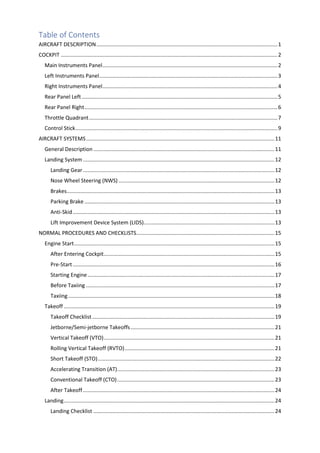
ATTENTION
The Fuel Shut Off lever locks in position when clicked ON. To click
it OFF, the [Fuel Shutoff Lever lock release] key must be pressed
first.](https://image.slidesharecdn.com/av8bnapocketguide-231006033505-3afcc52f/85/AV8BNA-Pocket-Guide-pdf-12-320.jpg)

![7 | P a g e
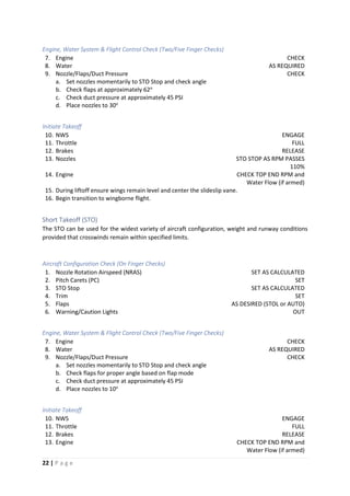
Throttle Quadrant
Description Keybind
1. Throttle [Throttle UP]
[Throttle DOWN]
Has Axis Control
2. ECM Dispense Switch [ECM Dispense FWD: Flares]
[ECM Dispense AFT: Chaff]
[ECM Dispense Left: Mini Jammer]
[ECM Dispense Right: All]
3. Cage/Uncage Switch [Cage/Uncage]
4. Antenna Elevation Switch NOT OPERATIONAL ON NA
5. Airstart Switch [Engine Airstart]
6. Emergency Flap Retract Switch [Emergency Flap Retraction]
7. Throttle Cutoff Lever [Throttle Cutoff]
8. Short Takeoff Stop [STO STOP UP]
[STO STOP DOWN]
9. Nozzles Control Lever [Nozzle Rotation UP]
[Nozzle Rotation DOWN]
Has Axis Control](https://image.slidesharecdn.com/av8bnapocketguide-231006033505-3afcc52f/85/AV8BNA-Pocket-Guide-pdf-14-320.jpg)
![8 | P a g e
Description Keybind
10. Parking Brake Lever [Parking Brake ON]
[Parking Brake OFF]
11. Jet Pipe Temperature Limiter Switch
12. EMS Button
13. Hovering Vertical Takeoff Stop
14. Throttle and Nozzle Lever Friction Knobs
15. Manual Fuel Control Switch
16. Rudder Trim Switch [Trim RUDDER LEFT]
[Trim RUDDER RIGHT]
17. Speed Brake Switch [Airbrake ON]
[Airbrake OFF]
[Airbrake TOGGLE]
18. COMM Switch [COMM UP: Select COMM 1]
[COMM DOWN: Select COMM 2]
19. A/A Programming NOT OPERATIONAL ON NA
20. TDC [TDC Forward]
[TDC Aft]
[TDC Left]
[TDC Right]
[TDC Down (Action Position)]
[TDC Action/No Action Toggle]
Has Axis Control](https://image.slidesharecdn.com/av8bnapocketguide-231006033505-3afcc52f/85/AV8BNA-Pocket-Guide-pdf-15-320.jpg)
![9 | P a g e
Control Stick
Description Keybind
1. Trigger [Trigger: Fire Gun/Launch Sidewinder, Sidearm]
2. Air-To-Ground Bomb Pickle Button [Bomb Pickle: Release Bombs/Launch Rockets,
Mavericks]
3. Trim Switch [Trim Pitch UP]
[Trim Pitch DOWN]
[Trim Bank LEFT]
[Trim Bank RIGHT]
4. Sensor Select Switch [Sensor Select FWD: INS. IRMV/EOMV]
[Sensor Select AFT: DMT: LST/TV]
[Sensor Select LEFT: MAP Center/Decenter]
[Sensor Select RIGHT: FLIR/HUD-BH/WH]
[Sensor Select DOWN: HUD Scene Reject/TPOD]
5. Waypoint Increment [WP Increment]](https://image.slidesharecdn.com/av8bnapocketguide-231006033505-3afcc52f/85/AV8BNA-Pocket-Guide-pdf-16-320.jpg)
![10 | P a g e
Description Keybind
6. Air-To-Air Weapon Select Switch [A/A Mode FWD: Sidewinder (Boresight)]
[A/A Mode AFT: Sidewinder (SEAM)]
[A/A Mode DOWN: Gun]
7. Undesignate/NSW Steering [AG Target Undesignate/NWS/FOV Toggle]
8. Emergency SAAHS Disengage
Switch
[Emergency SAAHS Disconnect]](https://image.slidesharecdn.com/av8bnapocketguide-231006033505-3afcc52f/85/AV8BNA-Pocket-Guide-pdf-17-320.jpg)

![12 | P a g e
Landing System
The landing systems consist of the landing gear, nosewheel steering, brakes, anti-skid and a lift
improvement device system (LIDS).
Landing Gear
The landing gear system consists of a nose gear, a main gear with twin wheels in tandem with the nose
gear and two single wheel wing gears.
Accidental retraction, when the aircraft is on the ground, is prevented by a weight-on-wheels (WOW)
switch and ground safety locks.
Landing Gear Handle
The landing gear handle is on the lower left main instruments panel. A mechanical downlock stop locks
the landing gear in the down position when the aircraft weight is on the main landing gear.
Landing Gear Position Indicators
The landing gear position indicators are on the lower left main instruments panel. The N (nose gear),
L (left wing gear), R (right wing gear) and M (main gear) green indicators come on when the respective
gear is down and locked. The N, L, R and M amber indicators are in-transit indicators and come one
when the respective gear is not down and locked or up and locked.
Landing Gear Warning Lights and Aural Tone.
The landing gear warning lights consist of the GEAR light on the upper right instrument panel and the
light in the landing gear handle. Both warning lights come on simultaneously.
The warning lights come on steady when any gear position disagrees with the landing gear handle
position.
With the landing gear handle in the up position, both warning lights will flash and a LANDING GEAR,
LANDING GEAR voice warning will sound when the aircraft altitude is below 6000 feet, airspeed is less
than 160 knots and the sink rate is over 250 feet per minute.
Nose Wheel Steering (NWS)
The NWS system is an electro-hydraulic operated system that provides directional control for ground
operations with three modes:
• CASTER: The default mode. Nose wheel is free to swivel, and rudder pedal movement is isolated
from the NWS system.
• LO GAIN Steering: The rudder pedals are connected to the system. Nose wheel has a range of
movement between -140
to +140
degrees.
• HI GAIN Steering: The nose wheel range of movement is increased to +/- 450
degrees. HI GAIN
steering is undesirable above 20 Knots Ground Speed due to poor directional control
characteristics.
A fourth steering mode, centered, is used for gear retraction. When the landing gear handle is placed
in the up position, the nose wheel will automatically steer to the center position at which time the
landing gear retraction will commence.
With the landing gear handle DOWN, the NWS mode is controlled by the anti-skid switch and the [AG
Target Undesignate/NWS/FOV Toggle] button on HOTAS. With anti-skid set to ON, CASTER mode is
selected. With the anti-skid switch set to NWS, LO GAIN steering is selected.](https://image.slidesharecdn.com/av8bnapocketguide-231006033505-3afcc52f/85/AV8BNA-Pocket-Guide-pdf-19-320.jpg)
![13 | P a g e
Pressing the [AG Target Undesignate/NWS/FOV Toggle] HOTAS button increases the steering mode
by one gain so that from CASTER mode it changes to LO GAIN mode and from LO GAIN mode it changes
to HI GAIN mode.
With the HUD in VSTOL mode, indications provide cues as to steering position and mode. Whenever
the nose wheel is within 30
of neutral, a C will appear inside the slideslip ball. A steering mode
indication is provided in the lower right hand corner of the HUD. The indications are:
CTR Centered
CAST Caster
NWS Lo gain
NWS H Hi gain
A NWS light, on the caution/advisory panel, illuminates to indicate that a steering failure has occurred.
Brakes
The twin-wheel main landing gear is equipped with hydraulic operated carbon disk brakes. An anti-
skid system and parking brake are also incorporated into the brake system. Both brakes operate
simultaneously and progressively as either brake pedal is depressed. There is no differential braking.
Two pressure indicators adjacent to the inboard side of the caution light panel, provide information
on brake accumulator pressure, and applied brake pressure.
Parking Brake
The parking brake handle is located outboard of the throttle. It can only be actuated by the [Parking
Brake ON] and [Parking Brake OFF] key binds. The parking brake can only be set when the throttle is
in idle. When the parking brake is set, the throttle cannot be advanced until the parking brake is
released.
Anti-Skid
The anti-skid system is an electro-hydraulic system that controls hydraulic pressure to the brakes
providing full skid protection above 16 knots. The anti-skid system is selected by the ANTI-SKID switch
located on the landing gear/flaps control panel. The switch is labeled TEST, ON and NWS. The anti-skid
system is not powered when the switch is in the NWS position.
A SKID warning light will turn on when the anti-skid system is OFF or failed.
Lift Improvement Device System (LIDS)
The lift improvement device system (LIDS) is part of the landing gear system. The LIDS, composed of
fixed strakes and a retractable fence, increase lift by 1200 pounds by directing the jet fountain energy
and reducing hot air reingestion in ground effect.
The LIDS fence normally extends and retracts with the landing gear. However, the fence may be
retracted to reduce conventional takeoff drag with the LIDS switch. The LIDS switch is located on the
pilot’s service panel on the left console and is a two-position lever locked switch.
RET Retracts LIDS fence.
NORM LIDS fence operates normally (default position).
A LIDS light on the caution panel indicates that the landing gear handle and the fence position do not
agree. The LIDS fence is down at speeds below 125 knots and automatically retracts above 125 knots.](https://image.slidesharecdn.com/av8bnapocketguide-231006033505-3afcc52f/85/AV8BNA-Pocket-Guide-pdf-20-320.jpg)


![19 | P a g e
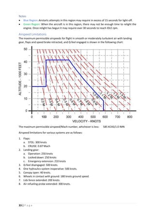
When Ready to Taxi:
1. Master Mode VSTOL
2. Nozzles 10o
3. Flaps CRUISE
4. Trim 0o
, 0o
, 4o
5. Anti-skid CHECK
6. Brakes/NWS CHECK
ATTENTION
The NWS is only engaged as long as the [AG Target Undesignate/NWS/FOV
Toggle] HOTAS button remains pressed. The NWS will disengage as soon as
the [AG Target Undesignate/NWS/FOV Toggle] button is released.
Pre-positioning Checks
Pre-positioning checks may be completed in the chocks, while taxiing, or while marshalling.
1. CWAIVER checks
C – Clock SET
W – Weapons PROGRAMMED
A – ARBS BORESIGHT
FLIR SET
I - IFF SET
IR cool switch AS DESIRED
V – VRS AS DESIRED
E – ECM (ALE/ALQ/ALQ) SET
R – RADALT SET
2. Canopy CLOSED/CHECK
3. Seat ARMED
4. Flight and standby instruments CHECK
5. APU AS DESIRED
6. ANTI-SKID ON (LIGHT OUT)
7. Altitude Switch AS DESIRED
8. INS Knob IFA/NAV
9. Approach Light ON
Takeoff
Four methods of takeoff are possible:
• Vertical Takeoff (VTO).
• Rolling Vertical Takeoff (RVTO).
• Short Takeoff (STO).
• Conventional Takeoff (CTO).
Takeoff Checklist
The following checklist is used to configure the aircraft for all four takeoff methods.
NOTE
Each aircraft cockpit contains a takeoff checklist placard. The contents of
these placards vary substantially from the takeoff checklist described in this
manual.](https://image.slidesharecdn.com/av8bnapocketguide-231006033505-3afcc52f/85/AV8BNA-Pocket-Guide-pdf-26-320.jpg)


![30 | P a g e
18. Throttle cutoff lever LIFT
19. Throttle OFF
After Engine shutdown
20. Fuel boost pump switches NORM
21. DECS enable switch OFF
22. Fuel shutoff handle OFF
(click on the [Fuel Shutoff Lever lock release] before trying to click
the handle to the OFF position)
23. Battery switch OFF
Air Refueling
Aerial refueling operations are authorized with all USN tankers and the KC-10. All tanker limits apply.
Ferry loading CG must be maintained by keeping the maximum water quantity below 250 pounds.
Before Plug-in checklist
1. Master Arm switch OFF
2. A/R switch OUT
(READY light ON)
3. Probe light AS DESIRED
4. Airspeed 190 to 300 KNOTS
5. AOA 13o
MAXIMUM
6. Flaps CRUISE
STOL flaps may be used to maintain AOA below 13o
.
Use of AUTO flaps is prohibited.
7. AFC ENGAGE IF DESIRED
(Reduces workload)
8. Visor DOWN
Refueling
Refueling altitudes and airspeeds are dictat3ed by receiver and/or tanker characteristics and
operational needs. This covers a practical spectrum, from the deck to 35,000 feet and 190 to 300
knots.
Approach
1. Complete the before plug-in checklist.
2. Assume a position 10 to 15 feet in trail of the drogue.
3. Keep the refueling probe in both the horizontal and vertical reference planes.
4. Trim the aircraft to keep this stabilized approach.
5. Select the drogue as the primary reference point on the tanker.
6. Set the power to establish an optimum 3 to 5 knots closure rate on the drogue.
7. Small corrections in the approach phase are acceptable:
a. Small lateral corrections are made with the rudder.
b. Small vertical corrections are made with the stabilator.
c. Avoid corrections in the longitudinal axis. They cause probe displacement in both the lateral
and vertical reference planes.
8. If alignment is off in the final phase abort and do over.](https://image.slidesharecdn.com/av8bnapocketguide-231006033505-3afcc52f/85/AV8BNA-Pocket-Guide-pdf-37-320.jpg)


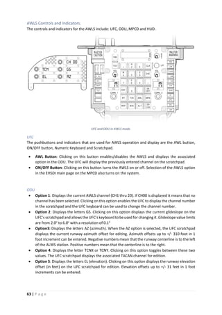


![70 | P a g e
SENSOR MANAGEMENT
The AV-8B Night Attack has three built-in sensors: The INS, Angle Rate Bombing System (ARBS) and
the FLIR. Of these three, the INS and the ARBS are used for target selection and ordnance delivery
computations.
Sensor Select Switch (SSS)
The sensor select switch is a six-position switch (center off). It uses five momentary positions: forward,
aft, left, right and down. The forward and aft selections are mutually exclusive but do not affect the
selections made with the left or right actuations.
• SSS Forward selects the INS sensor mode and in A/G, NAV or VSTOL master mode assigns the TDC
to the HUD. To provide a cue that the TDC is assigned to the HUD a dot is displayed in the middle
of the velocity vector.
If an IR or CCD Maverick missile is the selected weapon, this will activate the missiles seeker as the
aircraft’s targeting sensor. Subsequent actuations will toggle between INS and MAV sensor
modes.
• SSS Aft selects the ARBS sensor mode and in A/G, NAV or VSTOL master mode assigns the TDC to
the DMT. The first actuation sets the ARBS in Laser Spot Tracking mode (LST), the next actuation
sets the ARBS in TV mode. Subsequent actuations will toggle between LST and TV modes.
• SSS Left If no EHSD page is displayed in either MPCD, the first actuation will select the EHSD main
page in the Left MPCD. Subsequent actuations toggle between the EHSD center and decenter
modes.
• SSS Right If no FLIR display is selected in either MPCD, the initial actuation selects the FLIR display
in the right MPCD. Subsequent actuations toggle between FLIR white hot/black hot polarity.
• SSS Down Also known as the HUD scene reject. If the HUD brightness selector switch is in the
NIGHT position displays/reject FLIR video on the HUD. If the TPOD is loaded, it assigns the TDC to
the TPOD. Please refer to the LITENING II chapter for more information on the TPOD TDC
assignment.
Please refer to the control stick illustration to locate the Sensor Select Switch and its keybinds.
Target Designator Control (TDC)
The TDC is a switch with lateral displacements in all directions. It is located in the throttle for thumb
operation and incorporates both action and no action slewing in combination with fast and slow slew
rates. It is used for sensor designation slewing and commanding MAP, FLIR, INS or ARBS/TV sensor
designation.
TDC designates a target by clicking on the [TDC Down (Action Position)] key. Target designation occurs
upon key release.
Please refer to the throttle illustration to locate the TDC and its keybinds.
NOTE
TDC Action/No Action modes along with TDC axis command are not available
in the initial Early Release version. They will be made operational in
subsequent releases.](https://image.slidesharecdn.com/av8bnapocketguide-231006033505-3afcc52f/85/AV8BNA-Pocket-Guide-pdf-77-320.jpg)

![72 | P a g e
• MPCD: DMT video is displayed on either left or right MPCD. If DMT video was not available in any
MPCD, when the SSS requests DMT vide, the right MPCD will immediately change to DMT mode.
DMT switch in the Miscellaneous Control Panel
DMT Display
The DMT display can be called in two ways: By clicking on the DMT button (PB3) in the MPCD main
menu or by selecting the ARBS Sensor mode by clicking the [Sensor Select AFT: DMT: LST/TV] Key.
The DMT display has two modes:
• DMT without Video, and
• DMT with Video
DMT without video:
DMT without video is a special display in which the ARBS temporarily sets the INS as the main sensor
when for any reason the DMT TV camera cannot track a designated target, such as:
• When the ARBS is in LST mode and is trying to detect the laser spot.
• When the DMT TV/LST has reached its gimbal limits when tracking a designated target.
• When the DMT sun shutters have been activated to protect the lenses.
When DMT without video display is active, the DMT displays a page very similar to the EHSD main
page.](https://image.slidesharecdn.com/av8bnapocketguide-231006033505-3afcc52f/85/AV8BNA-Pocket-Guide-pdf-79-320.jpg)


![75 | P a g e
FLTR: The FLTR option selects which TV filter is used: yellow or red. Yellow filter for low light conditions
while Red filter is for normal light conditions. When Yellow filter is selected the FLTR legend will be
boxed.
Selected Sensor Status
In both DMT without video and DMT with video displays the selected sensor status is shown in the
upper left corner of the active display. The selected sensor status are:
• INS: When the selected sensor is the INS.
• LST: When the selected sensor is the ARBS in LST mode.
• TV: When the selected sensor is the ARBS in TV mode.
• MAV: When the selected sensor is IR or CCD Maverick missiles.
NOTE
All AV-8B NA video displays use green, not grey. Due to a DCS limitation we
have been forced to use greyscale. The video output will be changed to green
as soon as the texture is available in DCS.
ARBS Target Designation
When there is no designated target the ARBS/DMT sensors will be slaved to the Velocity Vector. The
recommended procedure to select and designate a target is to place the VVM on the selected target
and click on the [TDC Down (Action Position)] key.
LST Mode
Initially place the aircraft VVM in the general area where the laser spot is, the LST will soon move
towards the spot and lock it.
Once the spot has been locked the DMT with Video page will be displayed allowing the pilot to
visually track the target.
TV Mode
Either using the VVM in the HUD or the TV display, place the VV over the selected target and click [TDC
Down (Action Position)] key. Afterwards you can use the TDC to “sweeten” the target designation.
NOTE
Currently the ARBS/DMT TV Mode cannot lock to moving targets. This is still
under review. This option may or may not be available in the future
depending on available documentation.
NOTE
The ARBS/DMT sensor mode will be subject to modifications/upgrades after
the initial Early Release. Such changes will be informed in due time.
NOTE
INS designated targets can be transferred to the ARBS and vice versa. All you
have to do is change the selected sensor after the target has been designated.](https://image.slidesharecdn.com/av8bnapocketguide-231006033505-3afcc52f/85/AV8BNA-Pocket-Guide-pdf-82-320.jpg)
![76 | P a g e
FLIR
The AV-8B Night Attack has a built in FLIR system that is mainly used for navigation called NAVFLIR.
The NAVFLIR system consists of two main units: The sensor head and the electronics unit.
The NAVFLIR sensor head is mounted directly to a boresight adaptor tray in the upper portion of the
nose cone in front of the windscreen and is responsible for the distinctive fairing on the aircraft’s nose.
The electronics unit is located directly beneath the sensor head.
The NAVFLIR sensor head field-of-view (FOV) is fixed at the aircraft waterline and is 2o
above the
horizon in level flight. Its coverage is 13.4o
in elevation and 200
in azimuth. The sensor head detects IR
signals which is then converted to electrical signals in order to provide an analog representation of
the IR scene.
In order to detect the IR energy the sensor head must be cooled. Instead of using a liquid nitrogen like
the Sidewinder seeker head, the system uses a cooling engine that is powered by the aircraft. This
system provides slower cool down times (between three and five minutes depending on ambient
temperature) than the Sidewinder system.
NOTE
NAVFLIR cool down time is not enabled in initial Early Access release. The
system will be enabled in subsequent updates.
NAVFLIR Polarity
NAVFLIR polarity can be switched from White Hot to Black Hot and vice versa.
NAVFLIR Controls and Indicators
The NAVFLIR controls and indicators are: FLIR power switch, Sensor Select switch, HUD control panel
and either MPCD.
• FLIR power switch: The FLIR power switch is a two-position switch located on the NAVFLIR power
panel. The up position (FLIR) applies power to the NAVFLIR sensor and electronics unit. The down
position (OFF) removes power. When the switch is clicked to the FLIR position the NAVFLIR cool
down process is initiated. The NAVFLIR is operational in less than 5 minutes. Until then, with the
FLIR display selected on either MPCD a NOT RDY legend will be shown.
• Sensor Select Switch: Clicking on [Sensor Select RIGHT: FLIR: Video On/WH/BH] will select FLIR
video on the right MPCD, if FLIR video was not available before. Subsequent actuations will
alternate between white hot and black hot polarity.
Clicking on [Sensor Select DOWN: HUD Scene Reject/TPOD] will display FLIR video on the HUD, if
the HUD brightness selector is in the NIGHT position. Subsequent actuations of [Sensor Select
DOWN: HUD Scene Reject/TPOD] will toggle the FLIR video on the HUD between off and on.](https://image.slidesharecdn.com/av8bnapocketguide-231006033505-3afcc52f/85/AV8BNA-Pocket-Guide-pdf-83-320.jpg)

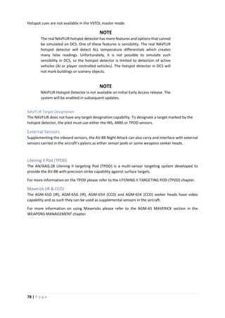


![88 | P a g e
Air-to-Ground
The A/G delivery modes are: automatic (AUTO), loft (LOFT), continuously computed impact point
(CCIP), air-to-ground missile (AGM), depressed sight line (DSL), direct (DIR) and DSL(1) a manual
mode. Loft is a submode of the automatic delivery mode, DSL, DIR and DSL(1) are backup delivery
modes.
STORE
DELIVERY MODE
AUTOMATIC
CCIP DSL AGM
AUTO LOFT
Bombs X X X X
Rockets X X
Gun X X
Dispensers
(illumination flares)
X X
Air-to-Ground
Missiles
X
AUTO Delivery Mode:
This mode works exactly as CCRP (Computer Controlled Release Point). It provides fully computed
automatic release of bombs. It requires that the target be designated either via INS, ARBS or TPOD,
in order to provide steering commands to the release point.
Steps:
1. Designate Target.
a. Azimuth Steering Line (ASL), Time-To-Go (TTG) and release cue (if in range) are displayed if
target is in the HUD FOV.
b. A steering arrow slaved to the VVM is displayed if the target is outside the HUD FOV. ASL, TTG
and release cue are removed from the HUD.
2. Follow the steering commands by executing appropriate delivery maneuvers.
3. When the release cue appears, press the [Bomb Pickle] until bomb release.
4. Bomb(s) will be automatically released.
LOFT Delivery Mode
This mode is not available in initial Early Access release. It will be enabled in subsequent updates.
CCIP Delivery Mode:
The Continuously Computed Impact Point (CCIP) delivery mode is a computed visual delivery mode
with manually initiated weapon release. It is selectable by the pilot for bomb deliveries. It is
automatically enabled by the ACP when rockets or the gun have been selected.
Bombs:
In CCIP mode, the ground impact point is continuously computed and displayed as a cross on the HUD.
The pilot’s task is to maneuver the aircraft so the CCIP cross is on the target, at which time the pilot
press the [Bomb Pickle] to release bomb
Rockets and Gun
In CCIP mode the aiming reticle is positioned over the computed impact point. The impact point is a
function of altitude and computed range to target. The pilot only has to maneuver the aircraft so the](https://image.slidesharecdn.com/av8bnapocketguide-231006033505-3afcc52f/85/AV8BNA-Pocket-Guide-pdf-95-320.jpg)
![89 | P a g e
target is inside the aiming reticle and press the [Trigger} for the gun or the [Bomb Pickle] for the
rockets.
DSL Delivery Mode
The DSL mode provides a weapons delivery capability should the avionics fail or the pilot feels that a
manual delivery is necessary. The DSL mode is only selectable on the ACP. On selection, the roll
stabilized reticle is displayed on the HUD.
DIR Delivery Mode
The DIR delivery mode provides a backup weapons delivery capability for limited weapons
employment. The system reverts to DIR when the SMC fails.
DIR mode can also be manually selected by deselecting all weapons, selectin A/G master mode and
then selecting DIR on the ACP. All weapons programing revert to a default state: FUZ to SAFE, QTY
and MULT to 1 and INTV to 0.
This mode uses the roll stabilized reticle on the HUD.
DSL(1) Delivery Mode
The DSL(1) (manual) mode is a backup delivery capability used when both the SMC and the ACP fail.
DSL(1) mode is selected by clicking the Manual Control to N,T or N/T. No weapons programming is
possible in this mode. This is the only mode in which different weapons type can be selected and
released.
This mode uses the roll stabilized reticle on the HUD.
NOTE
DSL(1) (manual) delivery mode is not enabled in initial Early Access release.
It will be enabled in subsequent releases.
AGM Delivery Mode
AGM Delivery mode is automatically selected by the ACP when an air-to-ground missile (AGM-65
Maverick or AGM-122 Sidearm). In this mode, the only weapons programming options available is
fuzing (for mavericks only).
Individual employment instructions for each missile are detailed in the next section
AGM-65E/TGM-65E Laser Maverick
This missile is not available on initial Early Access release. It will be enabled in subsequent releases.
AGM-65D/G and TGM-65D/G IR Maverick.
The AGM-65D/G IR Maverick (IRMV) is an imaging infrared guided, rocket propelled, air-to-ground
missile similar to the AGM-65E Laser Maverick (LMAV). The major difference between IRMV and LMAV
is in the seeker, or guidance control section.
The IRMV seeker tracks infrared (IR) significant targets and provides the pilot with a composite video
image of the target on the cockpit display. IRMV is capable of being slaved to a target designated by
the DMT or to the HUD with an INS designation.
IRMV is a fire and forget missile; however, IR targets must be identified by the pilot and IRMV manually
locked onto the target prior to launch.](https://image.slidesharecdn.com/av8bnapocketguide-231006033505-3afcc52f/85/AV8BNA-Pocket-Guide-pdf-96-320.jpg)
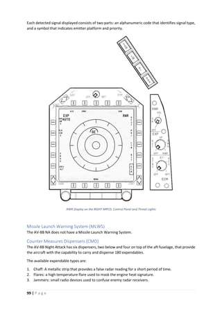
![90 | P a g e
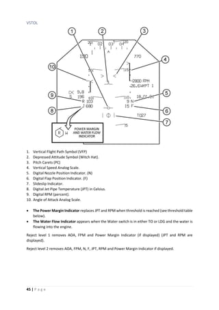
Stores Page with IR Maverick selected
Seeker Cool Down
Like all other infrared seekers, IR Maverick seeker must go through a 3 minute cool down process. The
cool down process can only be carried out once the aircraft is airborne (weight-off-wheels).
1. Select the STRS page in the MPCD.
2. Select the IRMV weapon in the top row.
3. All IR Mavericks will be powered and will start the cool down process.
4. The missiles status will be indicated above Button 20: STBY for cool down in process or RDY for
missiles ready.
5. Once the cool down process has ended the pilot can either select IR Video or deselect the weapons
(the missiles will remain in READY mode for an hour).
ATTENTION
IR Video is not available until the missiles are in READY mode.
IRMV Video Display
IRMV video is only available after the seeker cool down process has finalized (RDY appears on the
MPCD). IR Video is always displayed on the LEFT MPCD in place of the STRS display. To select IRMV
Video the pilot must press the [Cage/Uncage] HOTAS button. Subsequent activations of the
[Cage/Uncage] button will toggle the video on/off.
NOTE](https://image.slidesharecdn.com/av8bnapocketguide-231006033505-3afcc52f/85/AV8BNA-Pocket-Guide-pdf-97-320.jpg)
![91 | P a g e
IRMV Video appears on the stores (STRS) page of the LEFT MPCD with each
initial [Cage/Uncage] command. If another display is selected while IRMV
video is displayed (by pressing the MENU button), select MENU/STRS to
return to IRMV Video.
IRMV video cannot be displayed on the RIGHT MPCD.
IRMV Track Polarity (PLTY)
The track polarity function sets the missile seeker to track hot targets on a cold background (hot track)
or cold targets on a hot background (cold track). The appropriate track polarity must be selected prior
to commanding lock-on. When in hot track, the missile crosshairs are white, while in cold track the
crosshairs are black. IRMV initializes on hot track.
Clicking on the PLTY button in the MPCD will toggle between Hot and Cold Track.
IRMV Target Designation and Lock-on
When ready to engage a target, the IRMV should be selected and RDY.
1. Press the [Cage/Uncage] HOTAS Button to activate IRMV Video in the LEFT MPCD.
2. The missile seeker will be slaved to the HUD’s VVM. The VVM will show a second circle to indicate
that the IRMV seeker is slaved.
3. On the HUD the Missile Type legend will show the letter U, for uncaged.
4. Press the [Sensor Select FWD: INS. IRMV/EOMV] HOTAS Button to select the IRMV seeker as the
selected sensor. IRMV label will appear on the IRMV video page.
5. The pilot can designate a target by two methods:
a. By placing the HUD’s VVM on top of the target. In the IRMV Video page, the target will be in
the center of the crosshairs. To command lock press the [TDC Down (Action Position)] HOTAS
Button. The seeker will attempt lock as soon as the button is released.
b. By slewing the seeker by using the TDC button/axis. The seeker will attempt lock as soon as
the button/axis is released.
6. The seeker can be slewed after a target lock is achieved. In which case the lock is cleared and a
new lock is attempted.
NOTE
If the IR Maverick seeker fails to achieve lock or the lock is lost, the
crosshairs will retract to the edges of the IRMV video display. They will
remain there until the seeker is reset by either pressing the [AG Target
Undesignate/NWS/FOV Toggle] HOTAS button or by slewing the seeker
with the TDC buttons.
AGM-65H/K and TGM-65H/K EO Maverick.
The AGM-65H/K Electro Optical Maverick (EOMV) is an imaging guided, rocket propelled, air-to-
ground missile similar to the AGM-65D/G IR Maverick (IRMV). The major difference between EOMV
and IRMAV is in the seeker, or guidance control section.
The EOMV seeker tracks shadow contrast in a video image and provides the pilot with a video image
of the target on the cockpit display. EOMV is capable of being slaved to a target designated by the
DMT or to the HUD with an INS designation.
EOMV is a fire and forget missile; however, video targets must be identified by the pilot and EOMV
manually locked onto the target prior to launch.](https://image.slidesharecdn.com/av8bnapocketguide-231006033505-3afcc52f/85/AV8BNA-Pocket-Guide-pdf-98-320.jpg)
![92 | P a g e
Seeker Alignment
The EO seeker will start a boresight alignment when the missile is selected and the aircraft is airborne
(weight-off-wheels). This process takes a few seconds before the missile is RDY.
EOMV Video Display
EOMV video is only available after the boresight alignment process has finalized (RDY appears on the
MPCD). EO Video is always displayed on the LEFT MPCD in place of the STRS display. To select EOMV
Video the pilot must press the [Cage/Uncage] HOTAS button. Subsequent activations of the
[Cage/Uncage] button will toggle the video on/off.
NOTE
EOMV Video appears on the stores (STRS) page of the LEFT MPCD with
each initial [Cage/Uncage] command. If another display is selected while
IRMV video is displayed (by pressing the MENU button), select MENU/STRS
to return to IRMV Video.
EOMV video cannot be displayed on the RIGHT MPCD.
EOMV Target Designation and Lock-on
When ready to engage a target, the EOMV should be selected and RDY.
1. Press the [Cage/Uncage] HOTAS Button to activate EOMV Video in the LEFT MPCD.
2. The missile seeker will be slaved to the HUD’s VVM. The VVM will show a second circle to indicate
that the IRMV seeker is slaved.
3. On the HUD the Missile Type legend will show the letter U, for uncaged.
4. Press the [Sensor Select FWD: INS. IRMV/EOMV] HOTAS Button to select the EOMV seeker as the
selected sensor. IRMV label will appear on the EOMV video page.
5. The pilot can designate a target by two methods:
a. By placing the HUD’s VVM on top of the target. In the IRMV Video page, the target will be in
the center of the crosshairs. To command lock press the [TDC Down (Action Position)] HOTAS
Button. The seeker will attempt lock as soon as the button is released.
b. By slewing the seeker by using the TDC button/axis. The seeker will attempt lock as soon as
the button/axis is released.
6. The seeker can be slewed after a target lock is achieved. In which case the lock is cleared and a
new lock is attempted.
NOTE
If the EO Maverick seeker fails to achieve lock or the lock is lost, the
crosshairs will retract to the edges of the IRMV video display. They will
remain there until the seeker is reset by either pressing the [AG Target
Undesignate/NWS/FOV Toggle] HOTAS button or by slewing the seeker
with the TDC buttons.](https://image.slidesharecdn.com/av8bnapocketguide-231006033505-3afcc52f/85/AV8BNA-Pocket-Guide-pdf-99-320.jpg)


![95 | P a g e
break lock by pressing the [AG Target Undesignate/NWS/FOV Toggle] HOTAS button, but there is no
guarantee that the missile will not attempt lock on the same target again.
NOTE
After a Sidearm launch, the next missile may attempt lock on the same
target. To prevent that, deselect Sidearms and reselect again to clear the
seeker.
ATTENTION
The AGM-122A Sidearm is a short range weapon. Its maximum range is
16.5 Km (8.9 Nautical Miles). You will be inside the launch envelope of
many enemy SAMs systems when using the missile, so plan accordingly.
NOTE
The AGM-122A Sidearm is still under development and at initial Early
Release has a low hit probability. The missile reliability will be upgraded in
subsequent upgrades.
Weapons Jettison
Jettison is accomplished via the emergency jettison button or the selective jettison button on the ACP.
Emergency Jettison
Jettison all stores on all stations, including their suspension equipment. AIM-9s on Station 1 and
Station 7 are retained.
Interlocks
Landing Gear UP OR Aircraft is airborne (Weight Off Wheels).
Jettison Control
Emergency Jettison Button (see instruments panel guide).
Jettison Procedure
Click on the Emergency Jettison Button.
Selective Jettison
To activate selective jettison click the Selective Jettison Knob to the appropriate mode. All weapons
selection will be cleared and weapons selection on the MPCD and weapons delivery is inhibited.
FUEL
Allows selection of Stations 2, 3, 5 and 6 (wet stations) if they are carrying fuel tanks. Fuel tanks are
dropped in pairs: 2 and 6, then 3 and 5.
Interlocks
Landing Gear UP AND Aircraft is airborne (Weight Off Wheels).
Jettison Control
Selective Jettison Knob and Selective Jettison Pushbutton.
Jettison Procedure
1. Click the Selective Jettison Knob until it is pointing at the FUEL position.
2. All weapons selection will be cleared and all fuel tank carrying stations will be preselected.
3. Select the stations you want to jettison by clicking on their pushbuttons in the ACP.](https://image.slidesharecdn.com/av8bnapocketguide-231006033505-3afcc52f/85/AV8BNA-Pocket-Guide-pdf-102-320.jpg)


![101 | P a g e
Expendables dispensing programming.
This option is not available on initial Early Access release. It will be enabled in subsequent updates.
Expendables operation.
Expendables selected are controlled via the EXP switch on the ECM control panel (please refer to the
instruments panel description). The EXP switch is a five-position switch with the following options:
1. OFF: Power is removed from the system. No expendable can be dispensed.
2. AUT: The system selects the dispenser based on aircraft altitude and velocity vector.
3. UP: The dispensers on top of the aft fuselage will be used first. Only after they are empty, the
lower dispensers will be used.
4. DWN: The dispensers on the bottom aft fuselage will be used first. Only after they are empty, the
top dispensers will be used.
5. RWR: Option not available.
NOTE
On UP and DWN modes, if the selected expendable is not available on the
priority dispenser, the lower priority dispensers will be used.
Dispensing
Actual expendable dispensing is controlled via HOTAS buttons.
[ECM Dispense FWD: Flares]: Initiates dispensing of flares as programmed.
[ECM Dispense AFT: Chaff]: Initiates dispensing of chaff as programmed.
[ECM Dispense Left: Mini Jammer]: Initiates dispensing of jammers programmed. NOT
OPERATIONAL.
[ECM Dispense Right: All]: Initiates dispensing of ALL expendables (chaff, flares and jammers) as
programmed
Flare Salvo
Clicking on the FLR SAL button on the armament master switch panel initiates continuous flare
dispensing. This button overrides operational mode selection. All flare containing dispensers are used.
The release of flares will continue for as long as the FLR SAL button remains pressed.
Chaff and Jammers cannot be dispensed while the FLR SAL button is pressed.](https://image.slidesharecdn.com/av8bnapocketguide-231006033505-3afcc52f/85/AV8BNA-Pocket-Guide-pdf-108-320.jpg)


![110 | P a g e
2. TPOD Slew Control Mode (TDC)
This mode can be selected by clicking on the PB14 when the TPOD primary display page is
displayed. The TDC legend is underlined (TDC) to indicate that this is the operational TPOD TDC
control mode. Clicking on TDC will return to the default mode (Aircraft HOTAS Control Mode) and
remove the underline.
In this mode the TPOD captures all TDC commands. If the TPOD was in SLAVE mode, it will
automatically select AR track mode. When the TPOD designates a target, this target becomes the
aircraft’s selected target (A/C CMD LOS) and all aircraft sensors are automatically locked to it.
3. TPOD HOTAS Control Mode (HTS)
This mode can only be selected by double clicking the [Sensor Select DOWN: HUD Scene
Reject/TPOD] HOTAS button in less than 0.8 seconds. The PB14 legend displays HTS to indicate
that this is the TPOD TDC control mode. To exit this mode, either double click on [Sensor Select
DOWN: HUD Scene Reject/TPOD] HOTAS button or click on the PB14 to select any of the other
two modes: TDC or TDC.
In HTS mode, the aircraft TDC and Sensor Select Switch are controlled by the TPOD. The TPOD
obeys all TDC commands and can be controlled by the SSS HOTAS switch, but any TPOD target
designation is not considered an aircraft target designation and thus cannot be used for an attack
run.
The aircraft HOTAS controls are changed as follows
HOTAS Action Result
[Sensor Select DOWN: HUD
Scene Reject/TPOD]
Double clicked in less than
0.8 seconds.
Selects/Deselects TPOD
HOTAS Control Mode.
Held for more than 0.8
seconds.
HUD scene reject
[Sensor Select AFT: DMT:
LST/TV]
Clicked in less than 0.8
seconds.
Toggles between area and
point track modes (AR/PT).
Held for more than 0.8
seconds.
Selects INR track mode.
[Sensor Select LEFT: MAP
Center/Decenter]
Clicked in less than 0.8
seconds.
Toggles between wide and
narrow FOV (WD/NR).
Held for more than 0.8
seconds.
Enters LSS mode.
[Sensor Select RIGHT:
FLIR/HUD-BH/WH]
Clicked in less than 0.8
seconds.
Toggles between white hot
and black hot (WH/BH) FLIR
polarity.
Held for more than 0.8
seconds.
Toggles between CCD and
FLIR sensors.](https://image.slidesharecdn.com/av8bnapocketguide-231006033505-3afcc52f/85/AV8BNA-Pocket-Guide-pdf-117-320.jpg)
![111 | P a g e
HOTAS Action Result
[Sensor Select FWD: INS.
IRMV/EOMV]
Clicked Deselects TPOD video on the
MPCD and return to normal
aircraft HOTAS mode.
[AG Target
Undesignate/NWS/FOV
Toggle]
Clicked Enters SLAVE mode.
TPOD Modes of Operation
The Litening II system is used in different operational modes of the aircraft, each of them demanding
different pod functions and behaviors. Consequently, operation of the TPOD is divided into various
modes, which operate interactively with the aircraft modes. The TPOD provides six main operating
modes. The TPOD provides six main operating modes: power-up initialization, standby, air-to-ground,
navigation, air-to-air, and BIT. The aircraft master modes, along with MPCD pushbutton selection,
control the TPOD operating modes.
NOTE
The TPOD is automatically powered as soon as the aircraft generators are online. In
real life, the TPOD is turned on by the ground crew by engaging the ON/OFF power
switch in the umbilical connector. The pilot does not have any means to turn the TPOD
ON or OFF from inside the cockpit.
Initialization Mode
With power on, the TPOD perform initialization sequences and sets the default mode settings as
specified in the following table:
PARAMETER DEFAULT DISPLAY
Display Page Primary
Sensor CCD CCD (PB 5)
Laser State Laser safe SAFE (PB 6)
Laser Mode Training Laser TRNL (PB 9)
Sensor Tracking Control Aircraft HOTAS Control Mode TDC (PB 14)
The initialization display, which is displayed for 15 seconds after initial pod power-up or selection of
standby mode, includes the following:
a. Software version
b. Laser Mask Version.
c. Laser Code Table Version.
d. Software Checksum.
e. Aircraft Type.
The initialization, which includes alignment of the pod’s Inertial Measurement Unit (IMU), takes
approximately 3 minutes. After initialization, the pod starts FLIR cooling. FLIR cooling takes
approximately 6 to 8 minutes. The TPOD will display a FLIR not ready (F-NOTRDY) indication, to the
right of the legend PB 5 legend, centered on the MPCD screen](https://image.slidesharecdn.com/av8bnapocketguide-231006033505-3afcc52f/85/AV8BNA-Pocket-Guide-pdf-118-320.jpg)