This document provides an overview of the Software Engineering 2 course, including its aims, objectives, course contents, and recommended textbooks. The course aims to provide knowledge of techniques for estimating, designing, building, and ensuring quality in software projects. The objectives cover understanding software metrics, estimating project costs and schedules, quality assurance attributes and standards, and software analysis and design techniques. The course content includes topics like software metrics, estimation models, quality assurance, and object-oriented analysis and design. The document also summarizes several software engineering process models and risk management approaches.
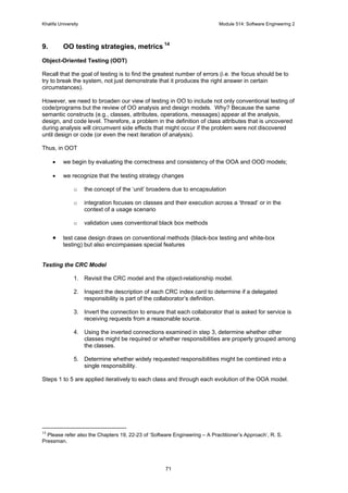
![Khalifa University Module 514: Software Engineering 2
3
1. A Review of Software Engineering
Software Engineering – A Definition1
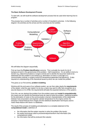
Software engineering is the branch of systems engineering concerned with the development of
large and complex software intensive systems.
It focuses on:
• the real-world goals for, services provided by, and constraints on such systems;
• the precise specification of system structure and behaviour, and the implementation of
these specifications;
• the activities required in order to develop an assurance that the specifications and real-
world goals have been met;
• the evolution of such systems over time and across system families.
It is also concerned with the:
• Processes
• Methods
• Tools
for the development of software intensive systems in an economic and timely manner.
Motivation
Consider the following statement2
“The scale of the software-dependent industry, often termed the secondary sector, extends far
beyond the conventional software sector. It is estimated that more than half of the world’s [1]
current software is “embedded” in other products, where it largely determines their functionality.
This percentage is set to increase dramatically over the next decade [2].
Software currently implements key, market-differentiating capabilities in sectors as diverse as
automobiles, air travel, consumer electronics, financial services, and mobile phones and is adding
major value in domestic appliances, house construction, medical devices, clothing and social
care.
Future competitive advantage will be based on the characteristics of products sold or services
provided. Many of those characteristics, such as functionality, timeliness, cost, availability,
reliability, interoperability, flexibility, simplicity of use or other qualities, will be largely software-
determined so that excellence in design, manufacturing or marketing will be to no avail without
appropriate software. For example, 90% of the innovation in a modern car is software-based.
Innovation, whether continuous or disruptive, will be delivered through quality software, and will
determine the success of more and more products and services.”
[1] In Germany the figure is greater than 70% (Source BMBF study 2001)
[2] “By 2010, there will be 16 billions Embedded Programmable Microcomponents (8 billions in
2003) or, in the average, 3 embedded devices per person worldwide” Artemis Technology
position paper, June 2004 ; Available at: http://www.cordis.lu/ist/artemis/background.htm
1
A. Finkelstein and J. Kramer, “Software Engineering: A Road Map” in "The Future of Software
Engineering", Anthony Finkelstein (Ed.), ACM Press 2000.
2
www.lero.ie: the Irish Software Engineering Research Centre](https://image.slidesharecdn.com/davidvernonsoftwareengineeringnotes-140402005508-phpapp01/85/David-vernon-software_engineering_notes-3-320.jpg)
![Khalifa University Module 514: Software Engineering 2
14
‘Software Engineering is Not Enough’
Software engineering courses and textbooks tend to emphasize the management aspects and
process aspects of software development (there is not one single program listing in the textbook4
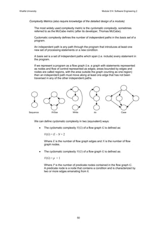
for this course).
While software engineering is certainly important, it is not everything.
The following points, taken from a recent article in IEEE Software5
, make the argument.
Software Development Is More Than Methodology (or Process, or Estimation, or Project
Management)
‘Software development is a fundamentally technical problem for which management solutions can
be only partially effective.’
‘Software development … is the hardest and least understood part of the software engineering life
cycle. Coding is immensely difficult without a good design but still very difficult with one.
Maintaining code is next to impossible without good documentation and formidable with it.’
‘There is no magic method that guarantees a well-engineered product.’
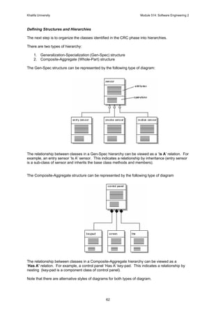
Programming is Hard
‘Programming remains monstrously complicated for the vast majority of applications.’
‘The only programs that are simple and clear are the ones you write yourself. When you have
written a program in its entirety, you have forced yourself to understand every aspect of the
problem and the solution.’
Documentation is Essential
‘There is rarely such a thing as too much documentation … the only hope for understanding
programs is good documentation of control structure blocks and detailed descriptions of the
purpose and use of data structures.’
‘Documentation – often exceeding the source code in size – is a requirement, not an option.’
You Must Validate Data
‘Good developers understand that they cannot trust user inputs. Each time an input enters the
system it must be validated to prevent failure or corruption of internal data.’
‘Developers quickly learn that every program has two parts: the code that performs the desired
function and the code that handles failure [and validation]’
‘You must painstakingly validate each parameter of each call, often meaning a lot of If statements
and calls to validation routines.’
‘Constraints on data and computation usually take the form of wrappers – access routines (or
methods) that prevent bad data from being stored or used and ensure that all programs modify
data through a single, common interface.’
4
R. Pressman, Software Engineering: A Practitioner’s Approach, McGraw-Hill, New York 1997.
5
J. A. Whittaker and S. Atkin, “Software Engineering Is Not Enough”, IEEE Software, July/August 2002, pp.
108-115.](https://image.slidesharecdn.com/davidvernonsoftwareengineeringnotes-140402005508-phpapp01/85/David-vernon-software_engineering_notes-14-320.jpg)
![Khalifa University Module 514: Software Engineering 2
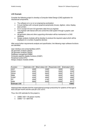
36
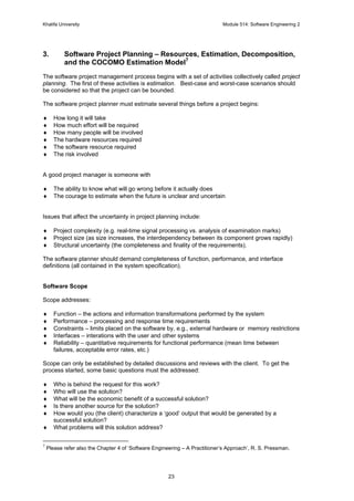
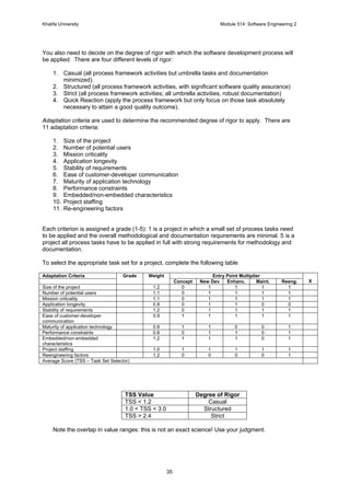
Selecting Software Engineering Tasks
In order to develop a project schedule, a task set must be distributed on the project time line.
The task set will vary according to the type of project and the degree of rigor. Depending on the
project time, you will choose an appropriate process model (e.g. waterfall, evolutionary, spiral).
This process is forms the basis for a macroscopic schedule for a project.
Once this is complete, you must then proceed to refine each of the major tasks, breaking them
into smaller composite tasks (remember: each sub-task also needs to have input and outcomes
specified). This process of task decomposition is exactly the same one as we use when
performing a function decomposition of the product during the specification phase of the software
life-cycle, i.e. you should aim to identify clear, distinct, modular, independent tasks with well-
defined inputs (typically the result of other tasks) and well-defined outputs (typically feeding into
other tasks).
Note well that this process of task identification and decomposition will be greatly aided if you
have a developed a rigorous and complete system specification (including all the supporting data,
functional, and process models: entity relationship diagrams, functional decomposition diagrams
[equivalently, the software architecture], data-flow diagrams, state-transition diagrams, etc.). If
these haven’t yet been created, then the schedule must be revisited and revised when they have.
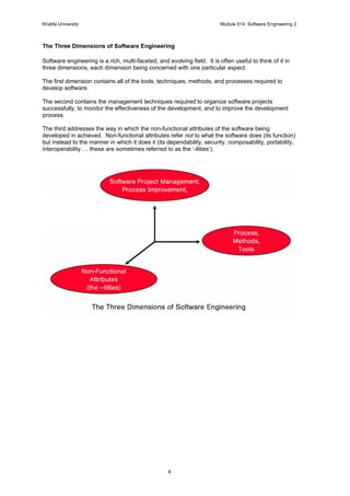
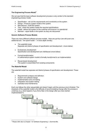
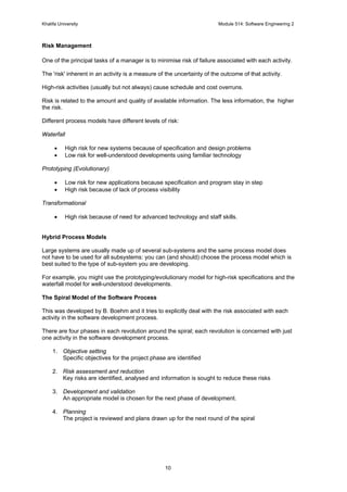
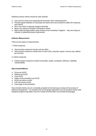
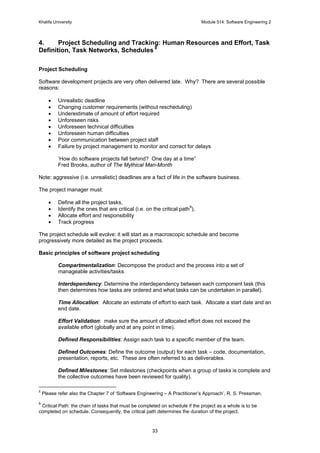
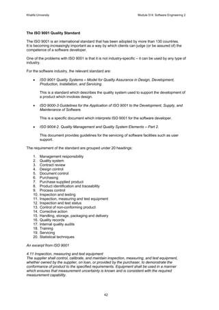
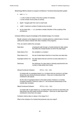
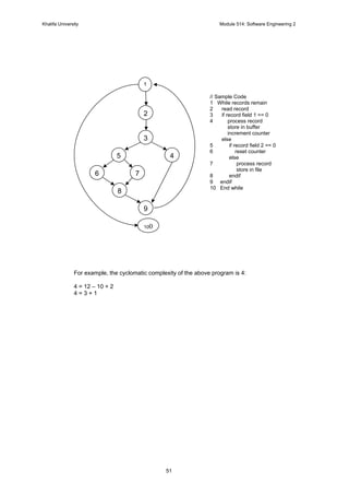
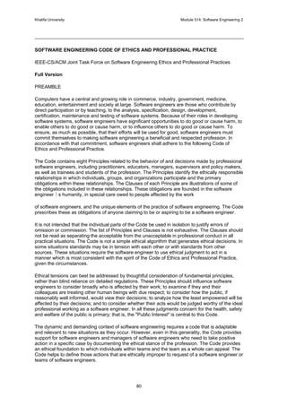
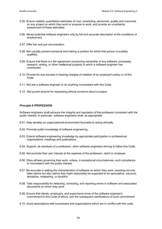
Creating a Task Network
Once this is complete, the next step is to create a task network. This is a graphic representation
of the task flow for a project and it makes explicit the dependencies, concurrency, and ordering of
component tasks. In addition, it allows the project manager to identify the critical path: the tasks
that must be completed on schedule in order to avoid any delay in the overall project schedule.
I.1
Concept
scoping
I.3a
Tech. Risk
Assessment
I.3b
Tech. Risk
Assessment
I.3c
Tech. Risk
Assessment
Three I.3 tasks are
applied in parallel to
3 different concept
functions
Three I.3 tasks are
applied in parallel to
3 different concept
functions
I.4
Proof of
Concept
I.5a
Concept
Implement.
I.5b
Concept
Implement.
I.5c
Concept
Implement.
I.2
Concept
planning
I.6
Customer
Reaction
Integrate
a, b, c](https://image.slidesharecdn.com/davidvernonsoftwareengineeringnotes-140402005508-phpapp01/85/David-vernon-software_engineering_notes-36-320.jpg)

![Khalifa University Module 514: Software Engineering 2
47
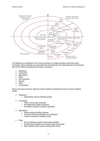
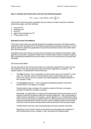
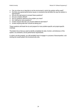
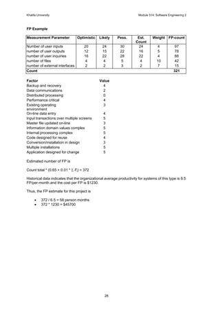
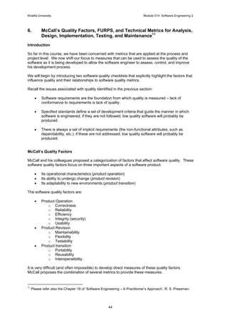
Technical Metrics for Analysis, Design, Implementation, Testing, and Maintenance
Metrics for the Analysis Model
These metrics examine the analysis model with the intent of predicting the size of the resultant
system. One of the most common size metrics is the Function Point (FP) metric.
The following metrics can be used to assess the quality of the requirements.
Specificity metric (lack of ambiguity)
rui nnQ /1 =
uin is the number of requirements for which all reviewers had identical interpretations
nffr nnn +=
rn is the total number of requirements
fn is the number of functional requirements
nfn is the number of non-functional requirements
Completeness of functional requirements
)/(2 siu nnnQ ×=
un is the number of unique function requirements
in is the number of inputs
sn is the number of states
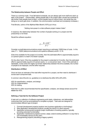
Metrics for the Design Model
Structural Complexity of a module i
)()( 2
ifiS out=
)(ifout is fan-out of module i (i.e. the number of modules that are called by module i)
Data Complexity of a module i
]1)(/[)()( += ifiviD out
)(iv is the number of input and output variables that are passed to and from module i
System Complexity of a module i
)()()( iDiSiC +=
)(iv is the number of input and output variables that are passed to and from module i](https://image.slidesharecdn.com/davidvernonsoftwareengineeringnotes-140402005508-phpapp01/85/David-vernon-software_engineering_notes-47-320.jpg)
![Khalifa University Module 514: Software Engineering 2
52
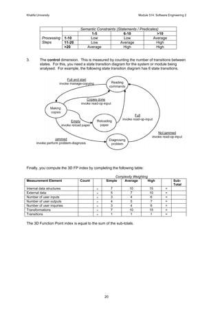
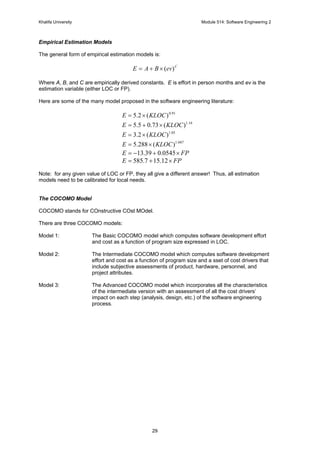
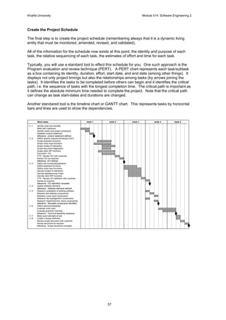
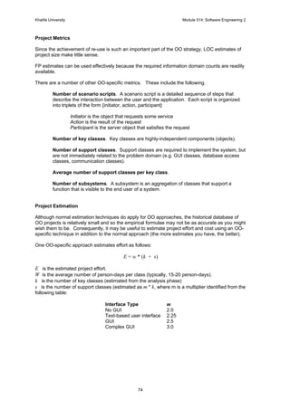
Interface Design Metrics
Graphic user interfaces, GUIs, require the placement of widgets (buttons, dialogue
boxes, scroll bars, etc) on a screen. The layout appropriateness metric, LA, is one
way of assessing the effectiveness of the interface (or, more specifically, the spatial
organization of the GUI; effectiveness is best measured by user feedback).
Define the cost C of performing a series of actions with a given layout as the sum of
the frequency of transition between a pair of widgets times the cost of that transition
(e.g. the distance a cursor must travel to accomplish the transition). The summation
is effected for all transitions required for a particular task.
C = Σ (f(k) / m(k))
where
f(k) is the frequency of a transition k
m(k) is the cost of a transition k
The summation is made for all k, i.e. all transitions.
The LA metric is then defined as follows:
LA = 100 x Co / Ci
where
Co is the cost of the optimal layout
Ci is the cost of the current layout
To compute the optimal layout for a GUI, the screen is divided into a grid, with each
square representing a possible position for a widget. If there are N positions in the
grid and K widgets, then the number of possible layouts is [ N! / K! x (N-K)! ] x K!
This is the number of possible combinations of K widgets in N spaces times the
number of permutations of widgets.
If N is large, you will need to use a non-exhaustive approach to finding the optimal
layout (e.g. tree search or dynamic programming).
LA is used to assess different proposed GUI layouts and the sensitivity of a particular
layout to changes in task descriptions (i.e. changes in the sequence or frequency of
transitions).](https://image.slidesharecdn.com/davidvernonsoftwareengineeringnotes-140402005508-phpapp01/85/David-vernon-software_engineering_notes-52-320.jpg)
![Khalifa University Module 514: Software Engineering 2
53
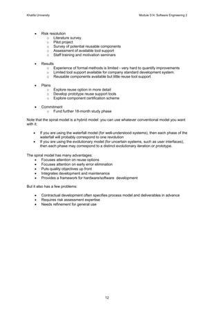
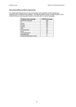
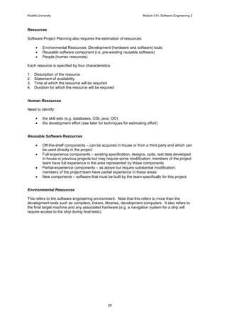
Metrics for Source Code
Halstead’s theory of software science defines a number of metrics for source code.
Define the following measures.
n1 be the number of distinct operators that appear in a given program (including the language
constructs such as for, while, do, case, … ).
n2 be the number of distinct operands that appear in a given program
N1 be the total number of occurrences of operators in a given program
N2 be the total number of occurrences of operands in a given program
Program length metric
N = n1 log2 n1 + n2 log2 n2
Program volume metric
V = N log2 ( n1 + n2 )
Halstead defines a volume ratio L as the ratio of volume of the most compact form of a given
program to the volume of the actual program:
L = 2 / n1 x n2 / N2
Metrics for Testing
Much has been written about software metrics for testing. However, most of this material focuses
on the testing process, rather than characteristics (quality) of the tests themselves.
In general, testers must rely on analysis, design, and code metrics to guide them in the design
and execution of test cases.
FP metrics can be used as a predictor of overall testing effort, especially when combined with
past experience in required testing.
The cyclomatic complexity metric defines the effort required for basis path (white box) testing; it
also helps identify the functions or modules that should be targeted for particularly rigorous
testing.
Metrics for Maintenance
IEEE Standard 982.1-1988 suggests a software maturity index (SMI) that provides an indication
of the stability of a software product based on changes that occur for each release of the product.
SMI = [ MT - (Fa + Fc + Fd )] / MT
where
MT = the number of modules in the current release
Fa = the number of modules in the current release that have been changed
Fa = the number of modules in the current release that have been added
Fa = the number of modules from the preceding release that were deleted in the current release.](https://image.slidesharecdn.com/davidvernonsoftwareengineeringnotes-140402005508-phpapp01/85/David-vernon-software_engineering_notes-53-320.jpg)
![Khalifa University Module 514: Software Engineering 2
57
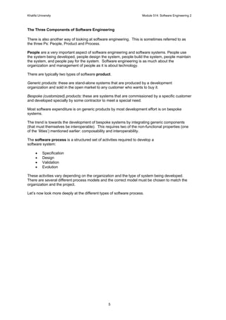
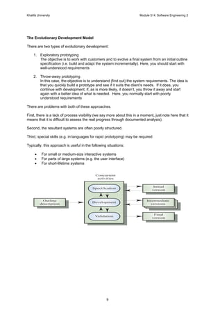
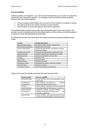
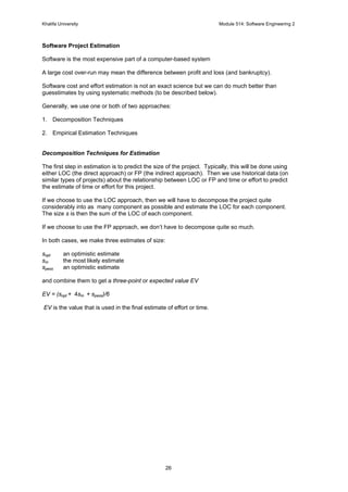
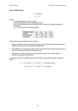
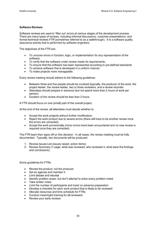
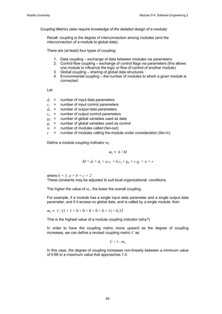
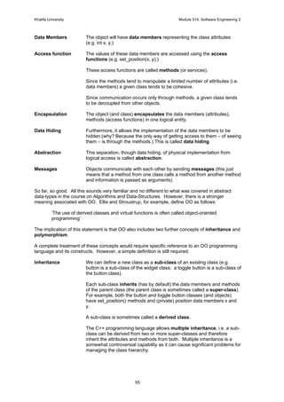
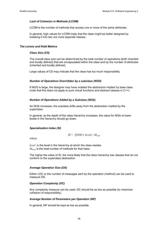
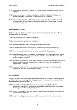
Message Passing Between Objects
sender object
attributes:
operations:
receiver object
attributes:
operations:
message: [receiver, operation, parameters]
message:
[sender, return value(s)]](https://image.slidesharecdn.com/davidvernonsoftwareengineeringnotes-140402005508-phpapp01/85/David-vernon-software_engineering_notes-57-320.jpg)

![Khalifa University Module 514: Software Engineering 2
88
Will strongly objected on obvious grounds. When he refused to yield, Tight brought charges
against him, claiming that he was a disruptive influence. Although his immediate superior, the
architect, did not support these charges, he did not fight for Morgan, who was ultimately
dismissed by the university. Morgan is now suing for wrongful discharge.
Making Good Wafers Look Bad
Don Fisher, an electrical engineer, worked for Dicers, a company that purchased wafers for
microprocessor chips from another company and then diced, packaged, and sold them. Don was
assigned the task of testing these wafers. After a while, he was instructed by his manager to alter
the testing process in such a manner that the quality of the purchased wafers was made to seem
lower than it really was, which had the effect of the lowering the price paid. Don objected to this
practice and refused to go along. Eventually, he was discharged .
Air Bags
SafeComp is a company that, among other things, designs and makes sensing devices for
automobile air bags. Bob Baines was hired to work in the quality control department. About six
weeks after starting work, he was asked to sign off on a design that he felt very uncertain about.
He checked with people involved in the design and found the situation, at best, ambiguous.
Bob told his manager that he would not feel right about signing off, and, since he was relatively
inexperienced with SafeComp's procedures, asked that he not be required to do this. His
manager kept applying pressure. Eventually, Bob decided that he wished neither to violate his
principles by doing something that he thought was wrong, nor to become involved in a battle in
which his career would certainly be major casualty. He quietly resigned. (For a little more
information on this case, see [3]).
Flight is also Risky
Ralph Sims had worked for the US Government for many years as an engineer, rising to a fairly
high managerial position. On retirement, he accepted an executive position with SuperCom, a
company producing electronic equipment for the military.
Shortly after coming on board, Ralph was informed by a subordinate that, for a long time, a key
test on an important product was not being made in the manner specified by the contract. This
had been going on for several years and the subordinate felt very uncomfortable about it. Ralph,
who had considerable expertise in the technology involved, looked into the matter carefully. It
turned out that, in his previous career, he had acquired some knowledge about the specified test.
He found that, a shorter, and hence less costly, test had indeed been substituted for the required
one. But, after some study, he concluded that SuperCom's test was actually as effective as the
specified test. Nevertheless, by this unauthorized substitution, SuperCom was violating the
contract and exposing itself both to criminal and to civil prosecution. He took his findings to upper
management and urged them to apply to the contracting agency for a contract change authorizing
the simpler test. Ralph felt confident that such a change would be accepted.
But his arguments were not accepted and SuperCom continued on their previous course. Ralph
did not see why he should get into an unpleasant battle with the SuperCom's leaders over this,
since there were no safety issues and even the quality of the product was not actually at stake.
Nevertheless, he did not wish to be involved in a dishonest and probably illegal operation.
Therefore, he chose the course of quietly resigning, without turning in the company.
About three years later, a SuperCom employee reported the deception to the government, and a
criminal investigation was launched. When he resigned, Ralph had signed a non-disclosure
agreement as a condition for receiving some severance pay. Nevertheless, when called upon by
the prosecutor's office to give information about the situation, he cooperated fully.
To his dismay, when the indictments came down, he was one of the people charged with
complicity in the fraud. This necessitated his hiring an attorney and undergoing both the expenses
and anguish of being a defendant in a criminal case. Fortunately for him, after many months, a](https://image.slidesharecdn.com/davidvernonsoftwareengineeringnotes-140402005508-phpapp01/85/David-vernon-software_engineering_notes-88-320.jpg)