Database Systems Design Implementation and Management 12th Edition Coronel Solutions Manual
Database Systems Design Implementation and Management 12th Edition Coronel Solutions Manual
Database Systems Design Implementation and Management 12th Edition Coronel Solutions Manual


![41
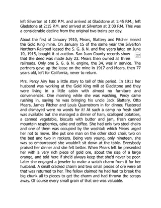
The branch to Green Mountain operated only a short time because
the mines up that way turned out to be poor producers. The part
from Eureka to Animas Forks is claimed never to have paid expenses
and soon quit regular operation though occasional trains ran up
there until sometime in the twenties. Mears offered the right-of-way
to the county if it would take up the track, which it did, and Mr.
Meyer hauled the junk down in 1936.
[4]
Like the S. R., it was a road
to begin with and ended up by being one again.
The section from Silverton to Eureka revived and lasted the longest
of any of the three little railroads. Ore was shipped over it from the
Sunnyside mine and mill until 1939 when the mine closed down
because of a miner’s strike.
In the summer of 1942 the property was advertised for sale for
$17,000 in delinquent taxes. Mrs. Cora Pitcher, Mears’s
daughter, sold it to the Dullen Steel Products Company and
paid the taxes. This company shipped the shop equipment, rails and
rolling stock out in October.
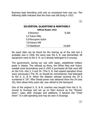
The United States had, after it became involved in war with Japan,
established military bases in Alaska. The railroad there, the White
Pass and Yukon, needed more motive power and the government
requisitioned the three locomotives, the 3, 4, and 34. There, so R. E.
Cooper states, they were re-numbered to 22, 23 and 24,
respectively. In 1947 word was received from the War Surplus Board
and the W. P. & Y. Ry. that twelve engines—7 D. & R. G., 2 C. & S.
and 3 S. N.—had been received by the Alaska Railroad but when
Diesel power was obtained there, all except No. 34 (24) were
returned to Seattle to M. Block & Co., a junking outfit. The last
known of the 34, it was sitting in the railroad yards at Skagway,
Alaska, in a state of dismantlement.
In 55 years, 1887 to 1942, the three little Silverton railroads started,
prospered, declined and perished and nothing, unless one considers
still discernible roadbeds and rotting ties, remains to attest their](https://image.slidesharecdn.com/12989-250518053943-069261df/85/Database-Systems-Design-Implementation-and-Management-12th-Edition-Coronel-Solutions-Manual-46-320.jpg)