Download to read offline

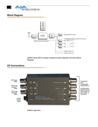


The document is a user manual for the AJA D10CE 10-bit Encoder SDI to Analog Converter. It converts serial digital video to analog composite and component outputs. Key features include 10-bit encoding, SDI and loop-through SDI outputs, and configurable analog outputs. The block diagram shows the signal path from SDI input through filtering and conversion to analog outputs.


