Download to read offline
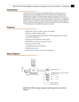


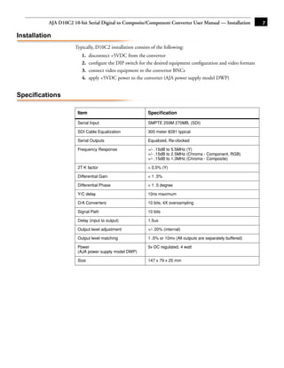

The document is the user manual for the AJA D10C2 10-bit Serial Digital to Composite/Component Converter. It converts serial digital video to analog composite or component video and provides two loop-through serial digital outputs. Key features include 10-bit encoding, SDI and analog outputs, configurable output formats via dip switches, and a limited 5 year warranty.


