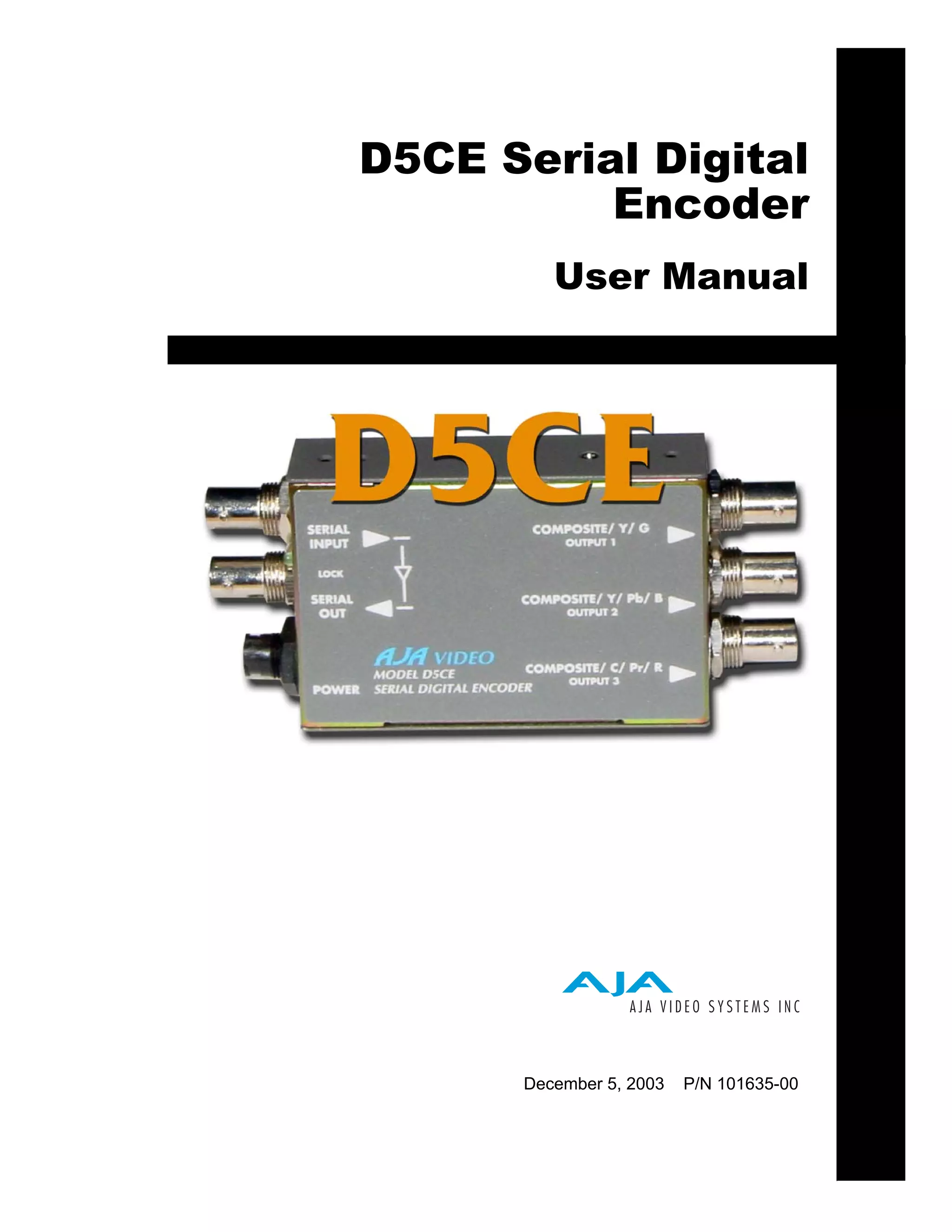
Download to read offline

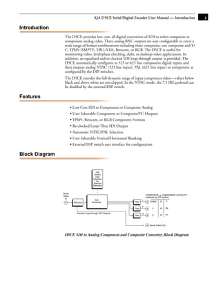


The document is the user manual for the AJA D5CE Serial Digital Encoder. It provides an overview of the product, describing its key features such as converting SDI to composite or component analog video, automatic NTSC/PAL selection, and re-clocked loop-through SDI output. It also outlines the product specifications, block diagram, input/output connections, and user interface which is a 4-switch DIP switch accessible through the bottom of the unit. The DIP switches are used to configure the output formats and settings.


