Download to read offline
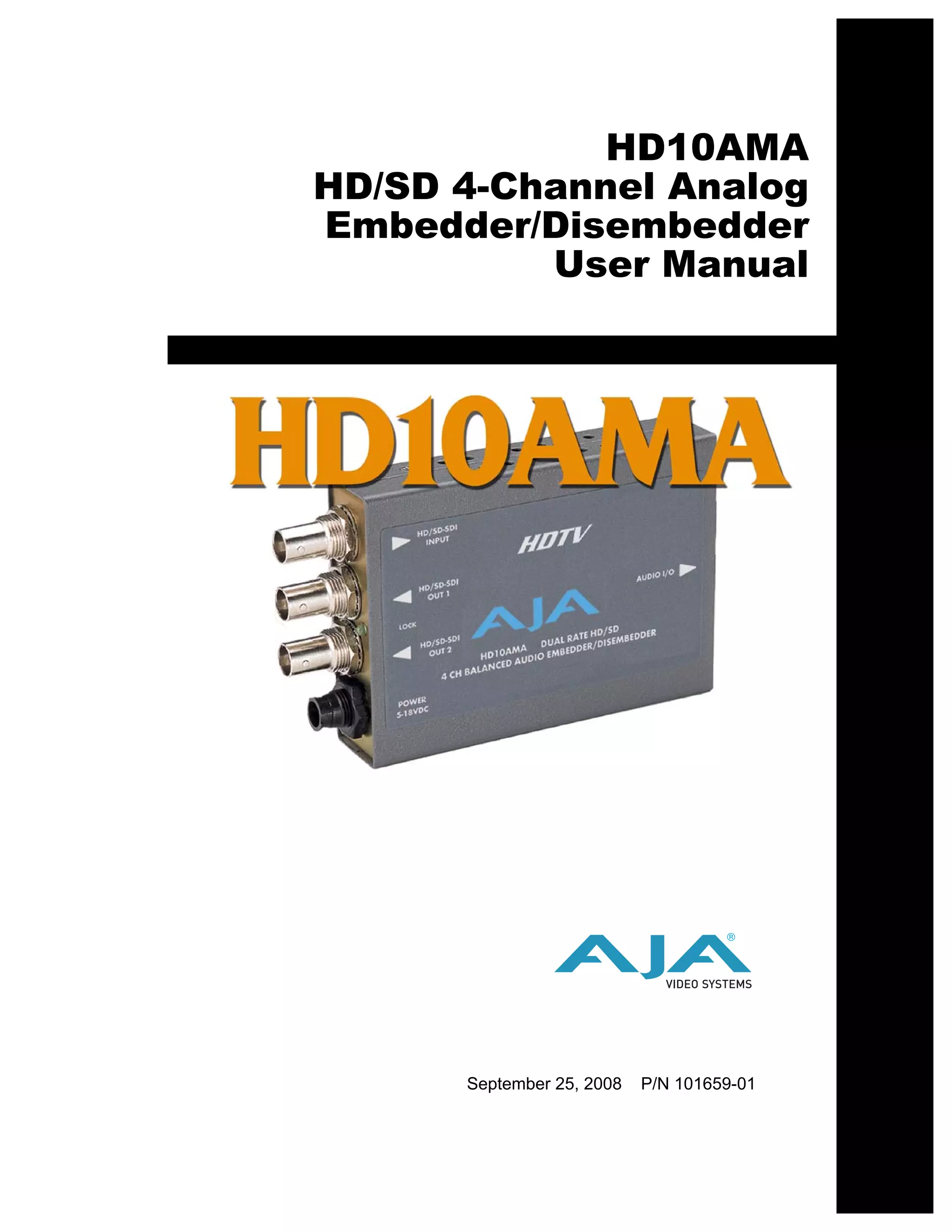
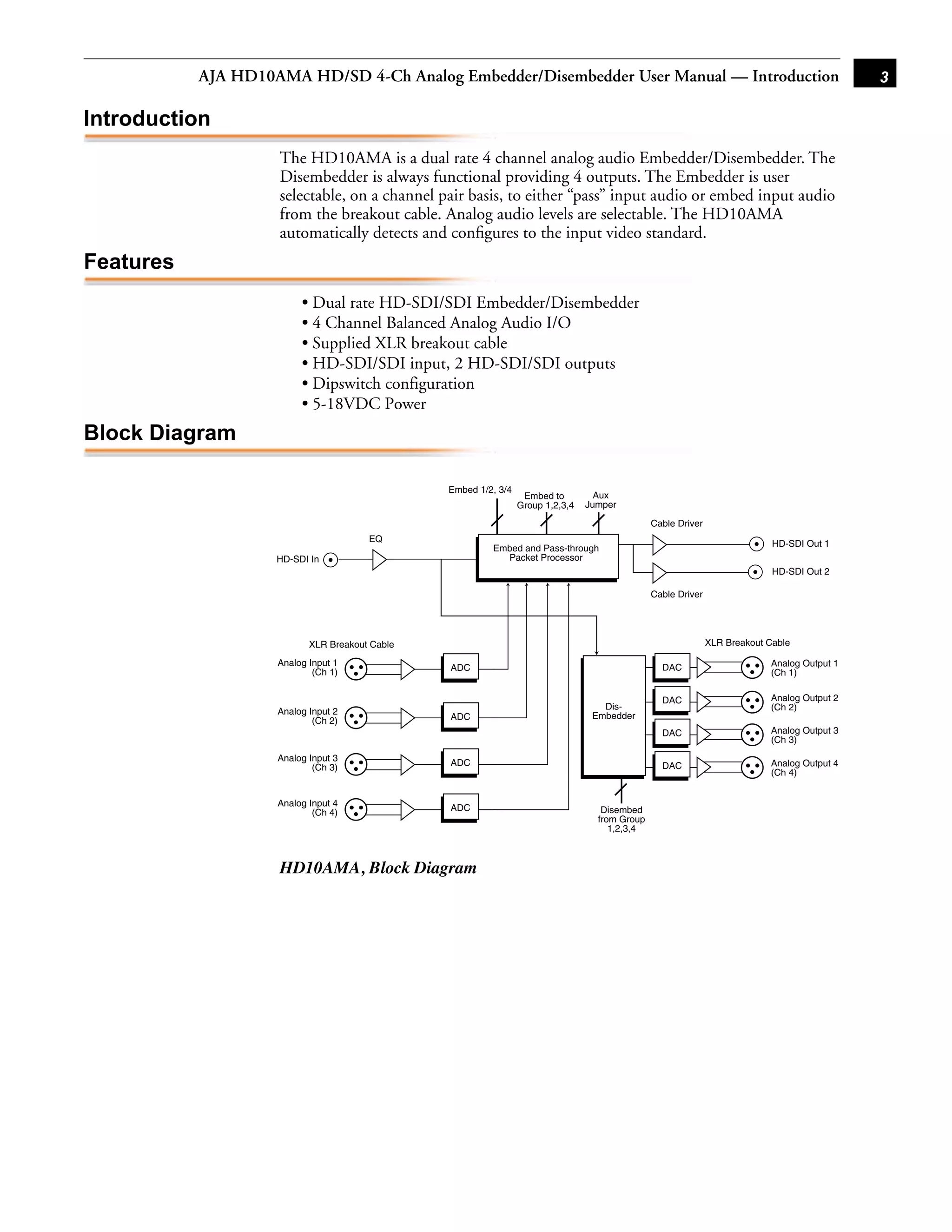
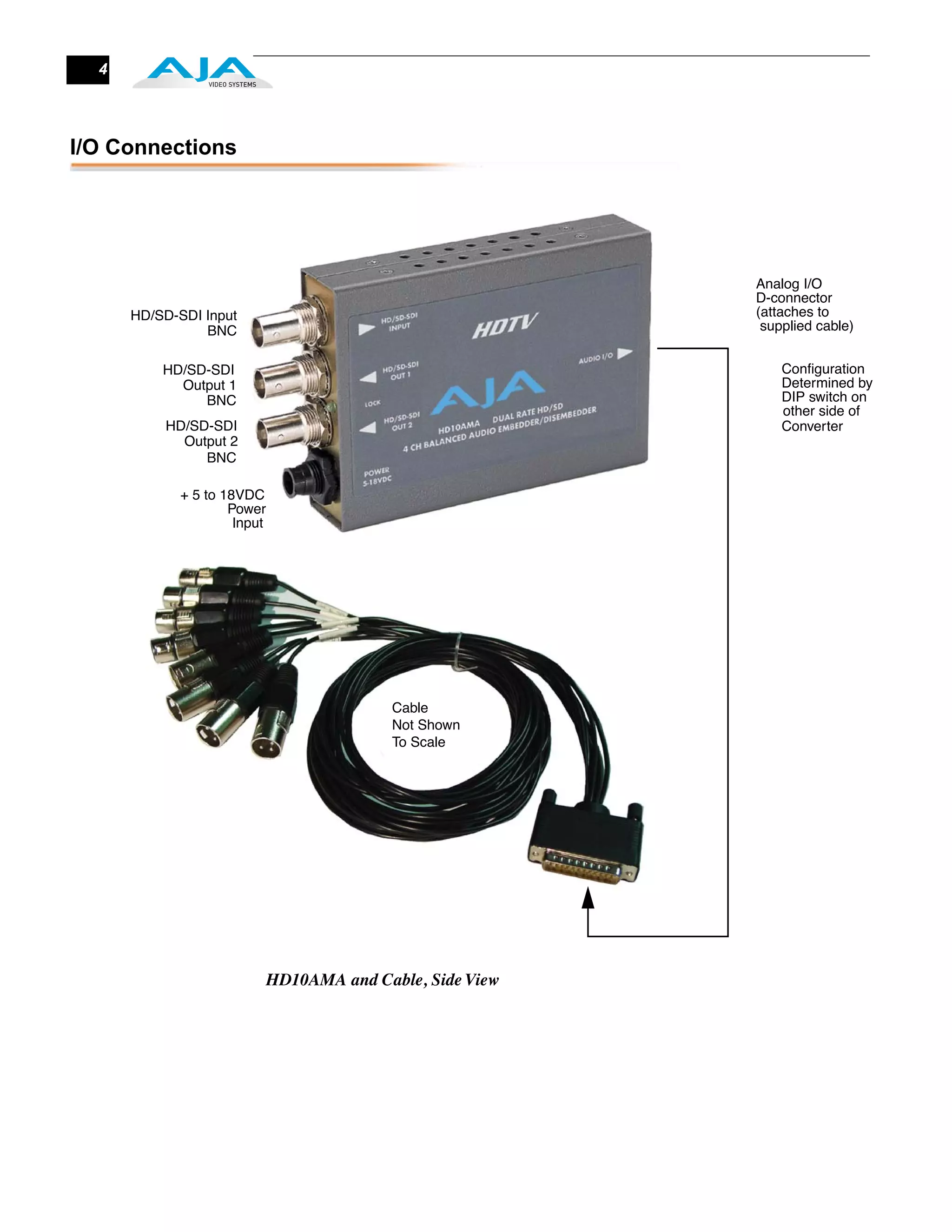

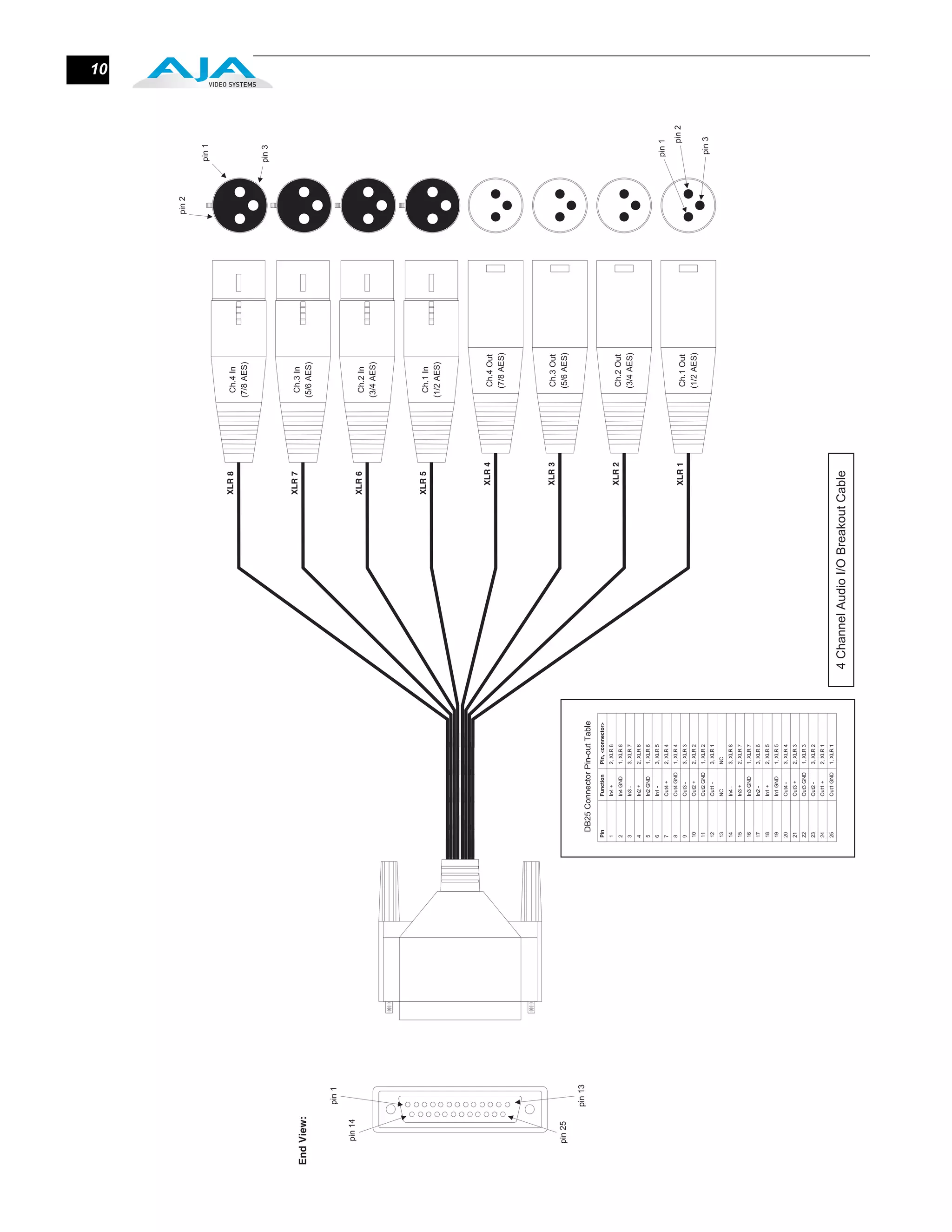

The document is a user manual for the AJA HD10AMA HD/SD 4-Channel Analog Embedder/Disembedder. It provides instructions on installing and configuring the device through its DIP switch settings to embed or disembed 4 channels of analog audio into HD-SDI or SD-SDI video signals. The device automatically detects the input video standard and features professional and consumer-level analog audio I/O through breakout cables with XLR connectors.


