Download to read offline
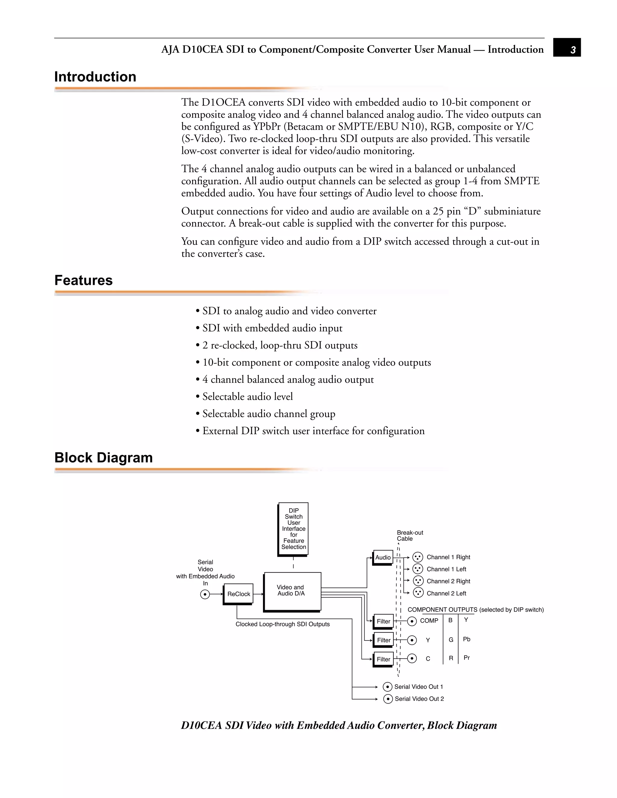
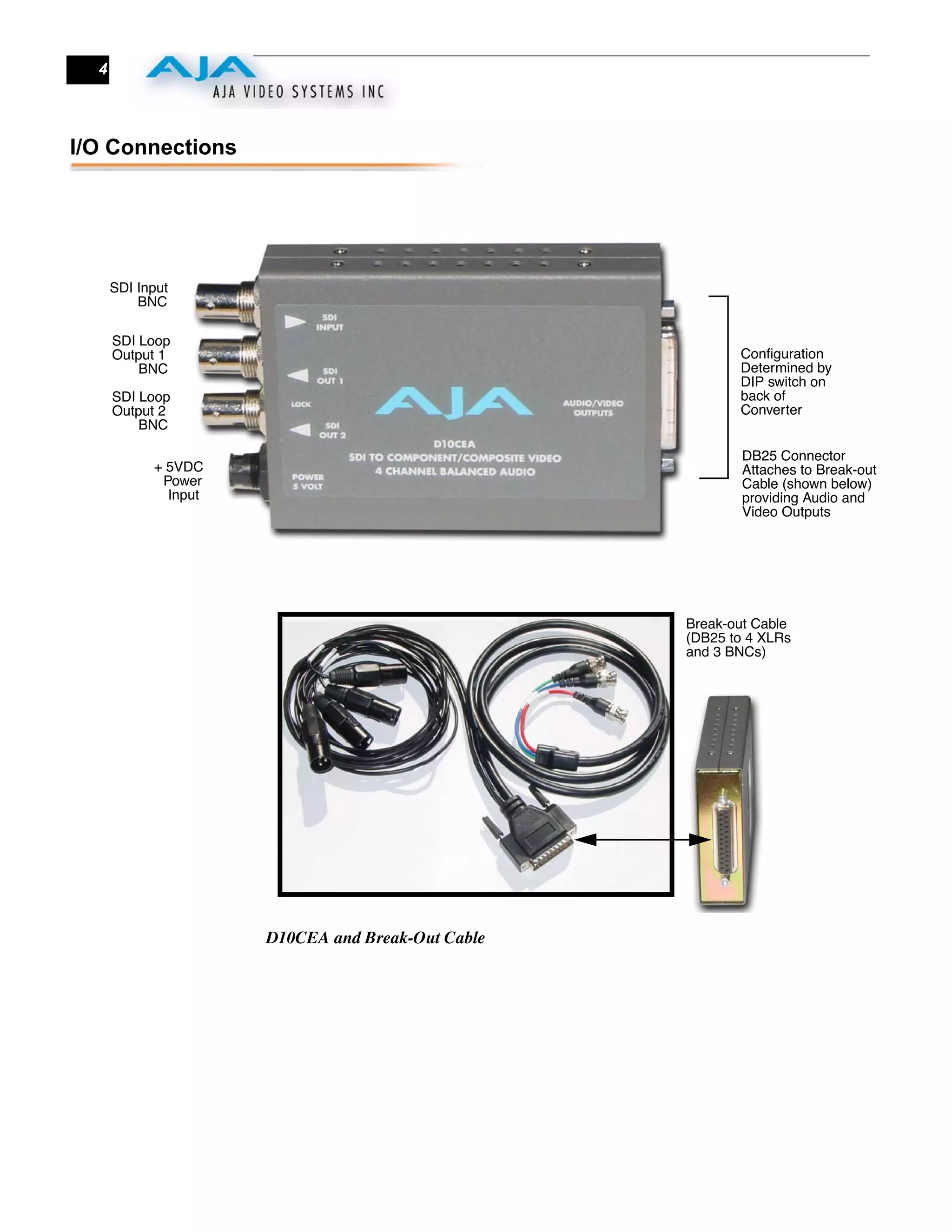
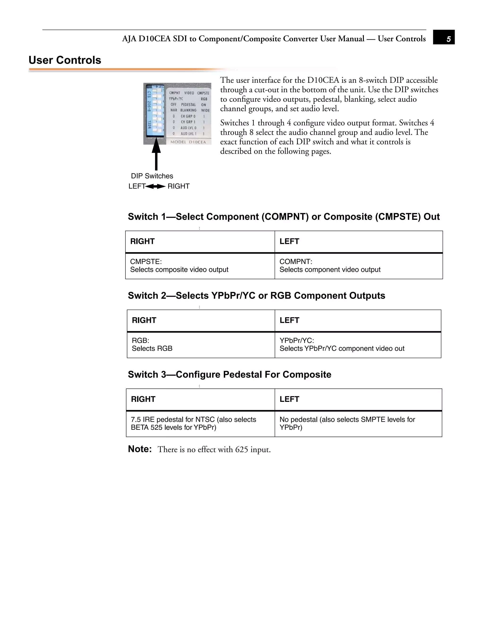
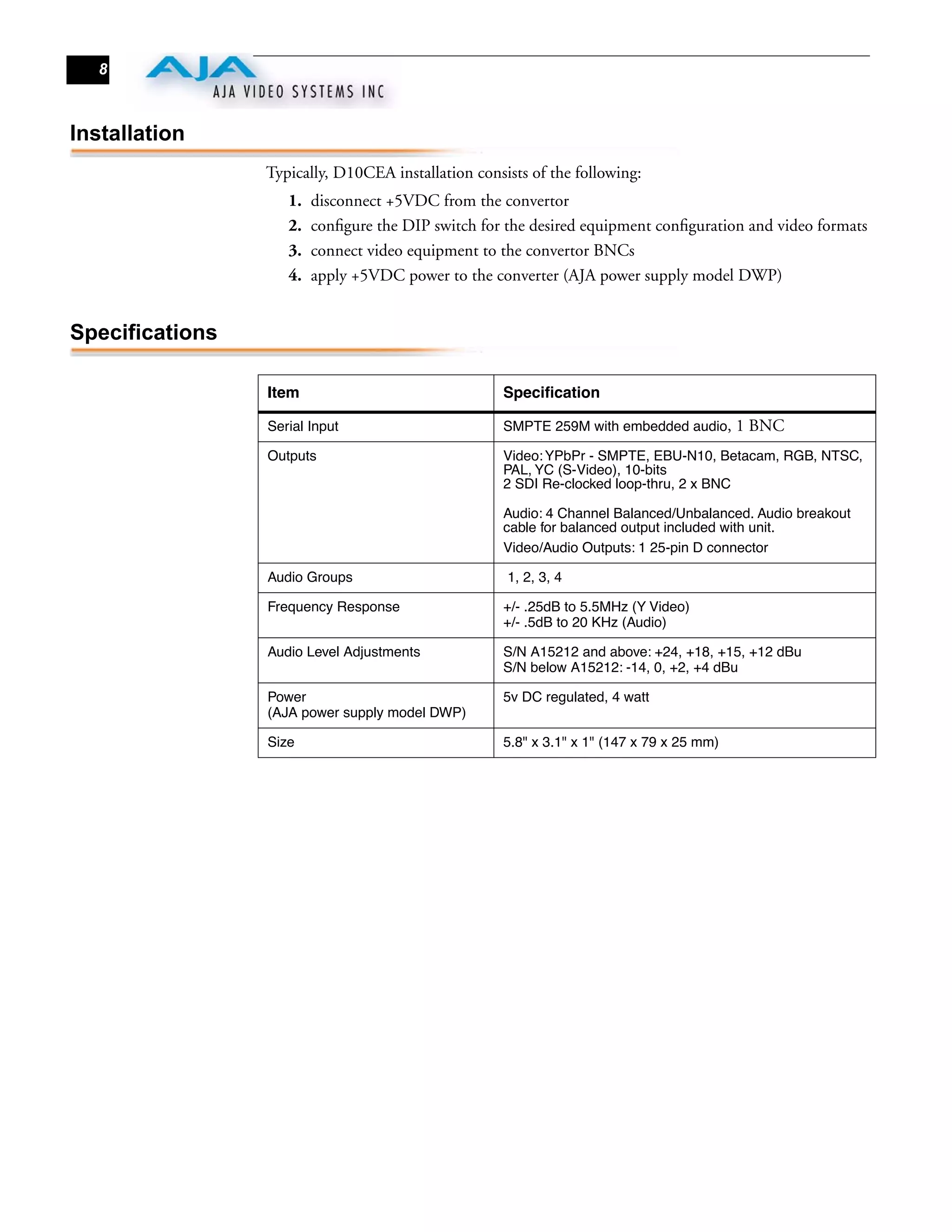

The document is the user manual for the AJA D10CEA SDI to Component/Composite Video with 4 Channel Audio Converter. It converts serial digital video with embedded audio to analog component or composite video and 4 channel balanced analog audio. Key features include selectable video and audio outputs, dual loop-through SDI outputs, and external DIP switch configuration. Connections include SDI input/output BNCs and a breakout cable providing video and audio outputs via a DB25 connector.


