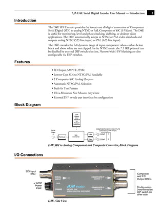
The document is the user manual for the AJA D4E Serial Digital Encoder. It provides an introduction and overview of the product, describing its key features such as SDI input/output, automatic NTSC/PAL selection, and test pattern generation. It also includes a block diagram, information on I/O connections, and details on the user interface DIP switches for configuration.
3. AJA D4E Serial Digital Encoder User Manual — Introduction 3
Introduction
The D4E SDI Encoder provides the lowest cost all-digital conversion of Component
Serial Digital (SDI) to analog NTSC or PAL Composite or Y/C (S Video). The D4E
is useful for monitoring, level and phase checking, dubbing, or desktop video
applications. The D4E automatically adapts to NTSC or PAL video standards and
outputs analog NTSC (525 line input) or PAL (625 line input).
The D4E encodes the full dynamic range of input component video—values below
black and above white are not clipped. In the NTSC mode, the 7.5 IRE pedestal can
be disabled by external DIP switch selection. Narrow/wide H/V blanking are also
configurable via DIP switches.
Features 1
• SDI Input, SMPTE 259M
• Lowest-Cost SDI to NTSC/PAL Available
• 2 Composite-Y/C Analog Outputs
• Automatic NTSC/PAL Selection
• Built-In Test Pattern
• Ultra-Miniature Size Mounts Anywhere
• External DIP switch user interface for configuration
Block Diagram
DIP
Switch
User
Interface
for
Feature
Selection
COMPOSITE OR Y/C OUTPUTS
Serial (selected by DIP switch)
Video 1
In Filter COMP Y
D/A
ReClock Converter
2
Filter COMP C
D4E SDI to Analog Component and Composite Converter, Block Diagram
I/O Connections
SDI Input
BNC Composite
and Y/C
Output BNCs
+ 5VDC
Power
Input Configuration
Determined by
DIP switch on
other side
D4E, Side View
4. 4
User Controls
The user interface for the D10CE is a 4-switch
DIP accessible through a cut-out in the
bottom of the unit. Use the DIP switches to
configure output, pedestal, blanking, and
enable or disable the test signal output.
Switches 1 through 3 control the format of the
output BNC. Switch 4 turns the test signal on
DIP Switches
and off. The exact function of each DIP switch
and what it controls is described on the OFF ON
following pages.
Dip Switch Functions All dip switches are accessible through a cut-out in the bottom of
the unit.
Switch 1—Selects Y/C or Composite Output at the 2 Output
BNCs
:
ON OFF
Selects Y/C (S-video) output at the two Selects composite video output at the two BNCs
BNCs)
Switch 2—Configure Blanking
:
ON OFF
WIDE Blanking: NARROW (NAR) Blanking:
Vertical— Vertical—
Line numbers indicate where video starts) Line numbers indicate where video starts
line 20, field 1; line 20, field 2 (525 line) line 13, field 1; line 12, field 2 (525 line)
line 23, field 1; line 336, field 2 (625 line) line 10, field 1; line 322, field 2 (625 line)
Horizontal— Horizontal—
Active video line duration Active video line duration's)
ITU-R/SMPTE (710 pixels NTSC, ITU-R.470 (720 pixels PAUNTSC)~-
702 pixels PAL)
Switch 3—Configure Pedestal For Composite/Sync BNC
:
ON OFF
7.5 IRE pedestal for NTSC (also selects No pedestal (also selects SMPTE levels for
BETA 525 levels for YPbPr) YPbPr)
Note: There is no effect with 625 input.
Switch 4—Turn Test Signal Output On or Off
5. AJA D4E Serial Digital Encoder User Manual — Installation 5
:
ON OFF
Output 75% Color Bars (requires a valid Normal Operation—no test signal is output
SDI input)
Notes:
1. The D4E is programmed for a 1.3 MHz chroma bandwidth when operating in
composite video mode. This provides the best quality video when encoding component
digital video. However with lower cost monitors, it may be desirable to reduce the
composite chroma bandwidth to 650 Khz to reduce the effects of cross-color artifacts.
This option is available from AJA Video as a special order.
1
2. The encoder D-to-A chip used in the D4E has an 8-bit input for component digital
video and 10-bit D-to0-A converters for the analog outputs. This configuration is often
described as an 8-bit “signal path” and 10-bit “Quantization.” Due to the internal
processing of the encoder chip, it is advantageous to use 10-bit D-to-A converters at the
output even though the input is 8-bits.
Installation
Typically, D10CE installation consists of the following:
1. disconnect +5VDC from the convertor
2. configure the DIP switch for the desired equipment configuration and video formats
3. connect video equipment to the convertor BNCs
4. apply +5VDC power to the converter (AJA power supply model DWP)
Specifications
Item Specification
Serial Input SMPTE 259M 270MB, (SDI)
SDI Cable Equalization 300 meter 8281 typical
Outputs NTSC/PAL, 2 BNC
Or NTSC/PAL Y/C, 2 BNC
Frequency Response +/- .25dB to 5.5MHz (Y)
+/- .25dB to 2.0MHz (Chroma - S-Video)
+/- .25dB to 1.3MHz (Chroma - Composite)
2T K factor < 1% (Y)
Differential Gain < 1 .5%
Differential Phase < 1 .5 degree
Y/C delay 10ns maximum
D/A Converters 10 bits
Signal Path 8 bits
Delay (input to output) 1.5us
Output level adjustment +/- 20% (internal)
6. 6
Item Specification
Output level matching 1 .5% or 10mv (All outputs are separately buffered)
Power 5v DC regulated, 2 watt
(AJA power supply model DWP)
Size 5.1" x 1.8" x 1" (131 x 44 x 25 mm)