Download to read offline

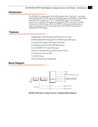
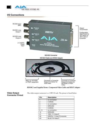
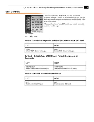
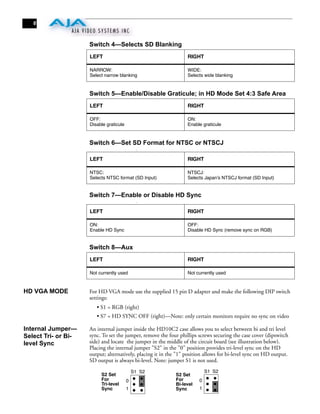
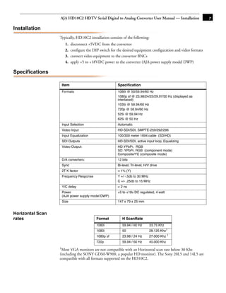


The document is the user manual for the AJA HD10C2 HDTV Serial Digital to Analog Converter. It provides an overview of the product, including its features, block diagram, I/O connections, user controls, installation instructions, and specifications. The HD10C2 converts HD-SDI and SDI video signals to analog component HD and SD outputs. It has dual HD-SDI loop outputs and is configured via front-panel DIP switches to set the output format and options.


