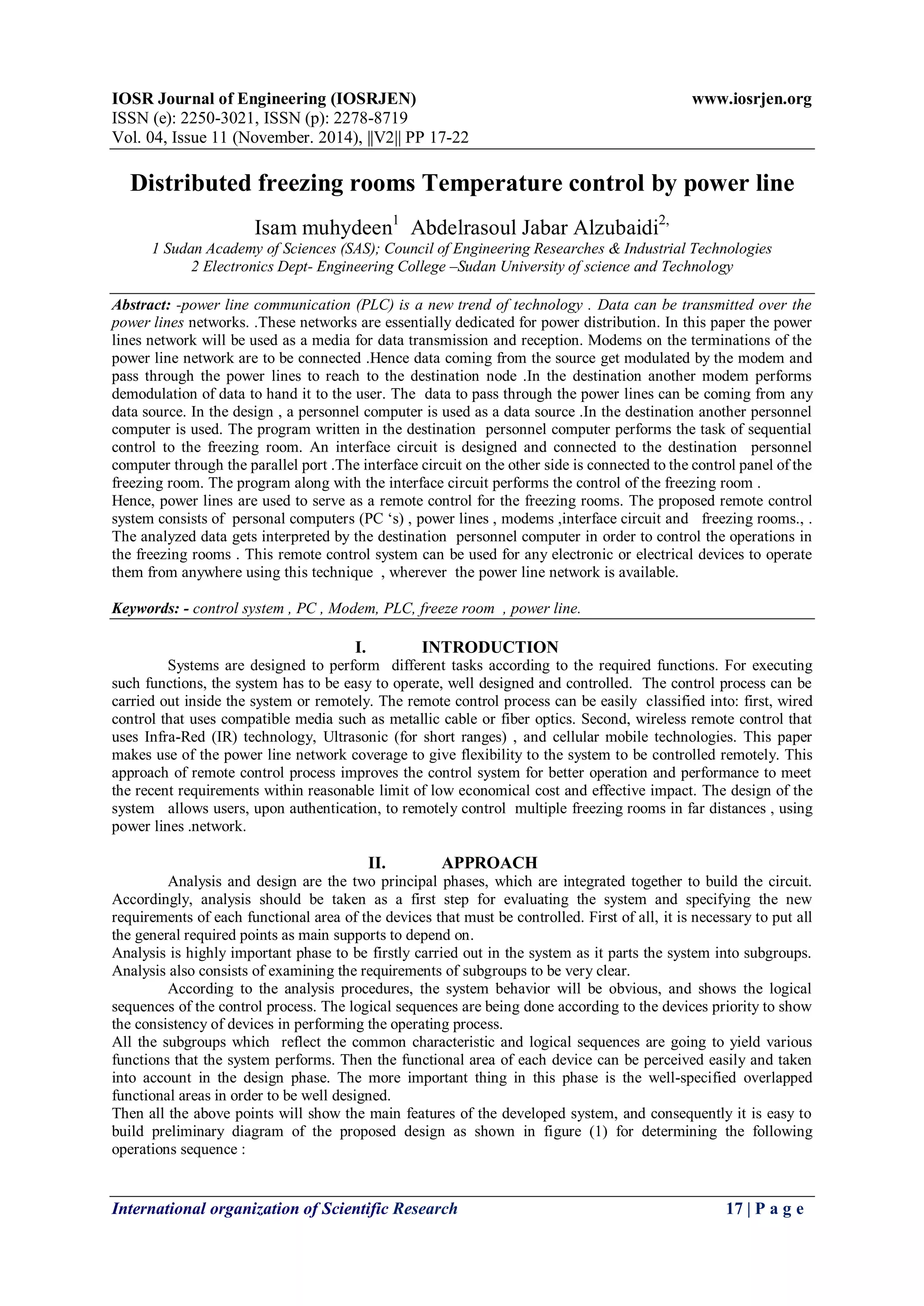
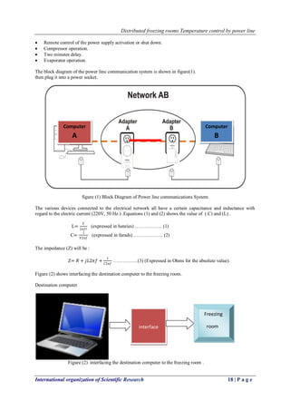
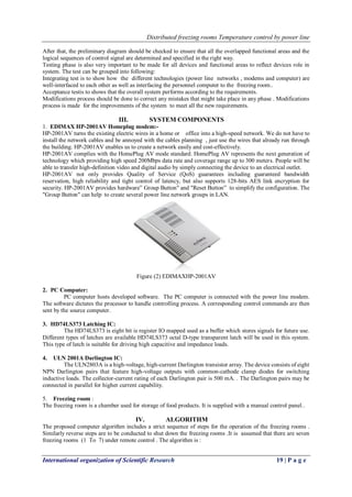
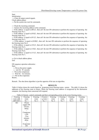
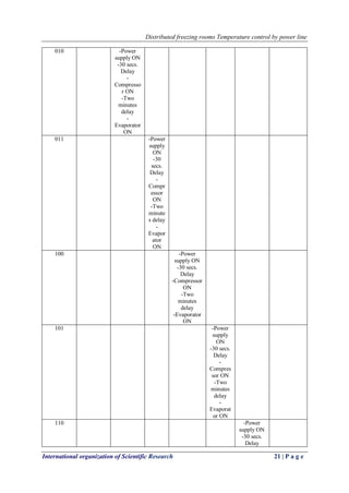
IOSR Journal of Engineering (IOSRJEN) www.iosrjen.org
ISSN (e): 2250-3021, ISSN (p): 2278-8719
Vol. 04, Issue 11 (November. 2014), ||V2|| PP 17-22
International organization of Scientific Research 17 | P a g e
Distributed freezing rooms Temperature control by power line
Isam muhydeen1
Abdelrasoul Jabar Alzubaidi2,
1 Sudan Academy of Sciences (SAS); Council of Engineering Researches & Industrial Technologies
2 Electronics Dept- Engineering College –Sudan University of science and Technology
Abstract: -power line communication (PLC) is a new trend of technology . Data can be transmitted over the
power lines networks. .These networks are essentially dedicated for power distribution. In this paper the power
lines network will be used as a media for data transmission and reception. Modems on the terminations of the
power line network are to be connected .Hence data coming from the source get modulated by the modem and
pass through the power lines to reach to the destination node .In the destination another modem performs
demodulation of data to hand it to the user. The data to pass through the power lines can be coming from any
data source. In the design , a personnel computer is used as a data source .In the destination another personnel
computer is used. The program written in the destination personnel computer performs the task of sequential
control to the freezing room. An interface circuit is designed and connected to the destination personnel
computer through the parallel port .The interface circuit on the other side is connected to the control panel of the
freezing room. The program along with the interface circuit performs the control of the freezing room .
Hence, power lines are used to serve as a remote control for the freezing rooms. The proposed remote control
system consists of personal computers (PC ‘s) , power lines , modems ,interface circuit and freezing rooms., .
The analyzed data gets interpreted by the destination personnel computer in order to control the operations in
the freezing rooms . This remote control system can be used for any electronic or electrical devices to operate
them from anywhere using this technique , wherever the power line network is available.
Keywords: - control system , PC , Modem, PLC, freeze room , power line.
I. INTRODUCTION
Systems are designed to perform different tasks according to the required functions. For executing
such functions, the system has to be easy to operate, well designed and controlled. The control process can be
carried out inside the system or remotely. The remote control process can be easily classified into: first, wired
control that uses compatible media such as metallic cable or fiber optics. Second, wireless remote control that
uses Infra-Red (IR) technology, Ultrasonic (for short ranges) , and cellular mobile technologies. This paper
makes use of the power line network coverage to give flexibility to the system to be controlled remotely. This
approach of remote control process improves the control system for better operation and performance to meet
the recent requirements within reasonable limit of low economical cost and effective impact. The design of the
system allows users, upon authentication, to remotely control multiple freezing rooms in far distances , using
power lines .network.
II. APPROACH
Analysis and design are the two principal phases, which are integrated together to build the circuit.
Accordingly, analysis should be taken as a first step for evaluating the system and specifying the new
requirements of each functional area of the devices that must be controlled. First of all, it is necessary to put all
the general required points as main supports to depend on.
Analysis is highly important phase to be firstly carried out in the system as it parts the system into subgroups.
Analysis also consists of examining the requirements of subgroups to be very clear.
According to the analysis procedures, the system behavior will be obvious, and shows the logical
sequences of the control process. The logical sequences are being done according to the devices priority to show
the consistency of devices in performing the operating process.
All the subgroups which reflect the common characteristic and logical sequences are going to yield various
functions that the system performs. Then the functional area of each device can be perceived easily and taken
into account in the design phase. The more important thing in this phase is the well-specified overlapped
functional areas in order to be well designed.
Then all the above points will show the main features of the developed system, and consequently it is easy to
build preliminary diagram of the proposed design as shown in figure (1) for determining the following
operations sequence :
Distributed freezing rooms Temperature control by power line
International organization of Scientific Research 18 | P a g e
 Remote control of the power supply activation or shut down.
 Compressor operation.
 Two minutes delay.
 Evaporator operation.
The block diagram of the power line communication system is shown in figure(1).
then plug it into a power socket.
figure (1) Block Diagram of Power line communications System
The various devices connected to the electrical network all have a certain capacitance and inductance with
regard to the electric current (220V, 50 Hz.) .Equations (1) and (2) shows the value of ( C) and (L) .
L=
𝑉
2𝜋𝑓𝐼
(expressed in henries) …………….. (1)
C=
𝐼
𝑉2𝜋𝑓
(expressed in farads) ……………… (2)
The impedance (Z) will be :
Z= 𝑅 + 𝑗𝐿2𝜋𝑓 +
1
𝐶2𝜋𝑓
……………(3) (Expressed in Ohms for the absolute value).
Figure (2) shows interfacing the destination computer to the freezing room.
Destination computer
Figure (2) interfacing the destination computer to the freezing room .
Computer
B
B
Computer
A
AA
interface
Freezing
room
Distributed freezing rooms Temperature control by power line
International organization of Scientific Research 19 | P a g e
After that, the preliminary diagram should be checked to ensure that all the overlapped functional areas and the
logical sequences of control signal are determined and specified in the right way.
Testing phase is also very important to be made for all devices and functional areas to reflect devices role in
system. The test can be grouped into following:
Integrating test is to show how the different technologies (power line networks , modems and computer) are
well-interfaced to each other as well as interfacing the personnel computer to the freezing room..
Acceptance testis to shows that the overall system performs according to the requirements.
Modifications process should be done to correct any mistakes that might take place in any phase . Modifications
process is made for the improvements of the system to meet all the new requirements.
III. SYSTEM COMPONENTS
1. EDIMAX HP-2001AV Homeplug modem:-
HP-2001AV turns the existing electric wires in a home or office into a high-speed network. We do not have to
install the network cables and be annoyed with the cables planning , just use the wires that already run through
the building. HP-2001AV enables us to create a network easily and cost-effectively.
HP-2001AV complies with the HomePlug AV mode standard. HomePlug AV represents the next generation of
technology which providing high speed 200Mbps data rate and coverage range up to 300 meters. People will be
able to transfer high-definition video and digital audio by simply connecting the device to an electrical outlet.
HP-2001AV not only provides Quality of Service (QoS) guarantees including guaranteed bandwidth
reservation, high reliability and tight control of latency, but also supports 128-bits AES link encryption for
security. HP-2001AV provides hardware” Group Button" and "Reset Button” to simplify the configuration. The
"Group Button" can help to create several power line network groups in LAN.
Figure (2) EDIMAXHP-2001AV
2. PC Computer:
PC computer hosts developed software. The PC computer is connected with the power line modem.
The software dictates the processor to handle controlling process. A corresponding control commands are then
sent by the source computer.
3. HD74LS373 Latching IC:
The HD74LS373 is eight bit is register IO mapped used as a buffer which stores signals for future use.
Different types of latches are available HD74LS373 octal D-type transparent latch will be used in this system.
This type of latch is suitable for driving high capacitive and impedance loads.
4. ULN 2001A Darlington IC:
The ULN2803A is a high-voltage, high-current Darlington transistor array. The device consists of eight
NPN Darlington pairs that feature high-voltage outputs with common-cathode clamp diodes for switching
inductive loads. The collector-current rating of each Darlington pair is 500 mA. . The Darlington pairs may be
connected in parallel for higher current capability.
5. Freezing room :
The freezing room is a chamber used for storage of food products. It is supplied with a manual control panel..
IV. ALGORITHM
The proposed computer algorithm includes a strict sequence of steps for the operation of the freezing rooms .
Similarly reverse steps are to be conducted to shut down the freezing rooms .It is assumed that there are seven
freezing rooms (1 To 7) under remote control . The algorithm is :
Distributed freezing rooms Temperature control by power line
International organization of Scientific Research 20 | P a g e
Start
Initialization :
--- Clear all output control signals.
Check address phase:
--- Put the system into wait for commands.
--- Check the incoming command..
--- Analyze the incoming address in the command..
--- If the address is equal to (001)2 , then call the turn ON subroutine to perform the sequence of operating the
freezing room No.1.
--- If the address is equal to (010)2 , then call the turn ON subroutine to perform the sequence of operating the
freezing room No.2.
--- If the address is equal to (011)2 , then call the turn ON subroutine to perform the sequence of operating the
freezing room No.3.
--- If the address is equal to (0100)2 , then call the turn ON subroutine to perform the sequence of operating
the freezing room No.4.
--- If the address is equal to (101)2 , then call the turn ON subroutine to perform the sequence of operating the
freezing room No.5.
--- If the address is equal to (110)2 , then call the turn ON subroutine to perform the sequence of operating the
freezing room No.6.
--- If the address is equal to (111)2 , then call the turn ON subroutine to perform the sequence of operating the
freezing room No.7.
--- Go to check address phase.
End.
ON sequence operation subroutine :
Start:
--- Put on the power supply.
--- wait for 30 seconds.
--- Put on the compressor.
---- Wait for two minutes.
----- Put on the evaporator.
Return..
Remark : The shut down algorithm is just the opposite of the turn on algorithm.
V. RESULTS
Table (1) below shows the results based on proposing seven freezing rooms system . The table (1) shows the
addresses of the freezing room in binary .When the freezing room address is recognized by the destination
computer ,the freezing room concerned will respond.
Table (1) System control commands and their corresponding action on the seven freezing rooms .
Freezing
room addr.
(BINARY)
Freezing
room
No. 1
Freezing
room
No. 2
Freezin
g room
No. 3
Freezing
room
No. 4
Freezing
room
No. 5
Freezing
room
No. 6
Freezing
room
No. 7
001 -Power
supply ON
-30 secs.
Delay
-
Compresso
r ON
-Two
minutes
delay
-
Evaporator
ON
Distributed freezing rooms Temperature control by power line
International organization of Scientific Research 21 | P a g e
010 -Power
supply ON
-30 secs.
Delay
-
Compresso
r ON
-Two
minutes
delay
-
Evaporator
ON
011 -Power
supply
ON
-30
secs.
Delay
-
Compr
essor
ON
-Two
minute
s delay
-
Evapor
ator
ON
100 -Power
supply ON
-30 secs.
Delay
-Compressor
ON
-Two
minutes
delay
-Evaporator
ON
101 -Power
supply
ON
-30 secs.
Delay
-
Compres
sor ON
-Two
minutes
delay
-
Evaporat
or ON
110 -Power
supply ON
-30 secs.
Delay
Distributed freezing rooms Temperature control by power line
International organization of Scientific Research 22 | P a g e
-
Compresso
r ON
-Two
minutes
delay
-
Evaporator
ON
111 -Power
supply ON
-30 secs.
Delay
-Compressor
ON
-Two
minutes
delay
-Evaporator
ON
VI. CONCLUSION
A remote control is an electronic device used for the remote operation of a machine. The designed circuit make
use of the already established power line networks to transmit data as a control signals and hence it can be used
for control from almost anywhere at any time once the power line network is available .Hence using data
commands, we can control any device remotely.
Security is essential to ensure that the system is accessible by the authorized persons only. Non authorized
commands to the system will be denied.
REFERANCES
[1] Manual on meat cold store operation and management By/Dr G. Cano-Muz ApriI.202008 .
[2] Remote control http://en.wikipedia.org/wiki/Remotecontrol April.1O.2008.
[3] Radio control httpengineeringtalk.com/ March. 15.2008
[4] History of remote control http://www.modellbah nottcom/tqpage/ihistory.html March.5.2008.
[5} Radio control httpengineeringtalk.com/ March. 15.2008.
[6] Ivan Stojmenovic, HandBook of Wireless Networks and Mobile computing, John Wiley & Sons Inc.,
2002.
[7] Iwao Sasase, Research Activities on the 4th Generation Mobile Communications and Ad-Hoc Networks,
2005.

D041121722

  • 1.
    IOSR Journal ofEngineering (IOSRJEN) www.iosrjen.org ISSN (e): 2250-3021, ISSN (p): 2278-8719 Vol. 04, Issue 11 (November. 2014), ||V2|| PP 17-22 International organization of Scientific Research 17 | P a g e Distributed freezing rooms Temperature control by power line Isam muhydeen1 Abdelrasoul Jabar Alzubaidi2, 1 Sudan Academy of Sciences (SAS); Council of Engineering Researches & Industrial Technologies 2 Electronics Dept- Engineering College –Sudan University of science and Technology Abstract: -power line communication (PLC) is a new trend of technology . Data can be transmitted over the power lines networks. .These networks are essentially dedicated for power distribution. In this paper the power lines network will be used as a media for data transmission and reception. Modems on the terminations of the power line network are to be connected .Hence data coming from the source get modulated by the modem and pass through the power lines to reach to the destination node .In the destination another modem performs demodulation of data to hand it to the user. The data to pass through the power lines can be coming from any data source. In the design , a personnel computer is used as a data source .In the destination another personnel computer is used. The program written in the destination personnel computer performs the task of sequential control to the freezing room. An interface circuit is designed and connected to the destination personnel computer through the parallel port .The interface circuit on the other side is connected to the control panel of the freezing room. The program along with the interface circuit performs the control of the freezing room . Hence, power lines are used to serve as a remote control for the freezing rooms. The proposed remote control system consists of personal computers (PC ‘s) , power lines , modems ,interface circuit and freezing rooms., . The analyzed data gets interpreted by the destination personnel computer in order to control the operations in the freezing rooms . This remote control system can be used for any electronic or electrical devices to operate them from anywhere using this technique , wherever the power line network is available. Keywords: - control system , PC , Modem, PLC, freeze room , power line. I. INTRODUCTION Systems are designed to perform different tasks according to the required functions. For executing such functions, the system has to be easy to operate, well designed and controlled. The control process can be carried out inside the system or remotely. The remote control process can be easily classified into: first, wired control that uses compatible media such as metallic cable or fiber optics. Second, wireless remote control that uses Infra-Red (IR) technology, Ultrasonic (for short ranges) , and cellular mobile technologies. This paper makes use of the power line network coverage to give flexibility to the system to be controlled remotely. This approach of remote control process improves the control system for better operation and performance to meet the recent requirements within reasonable limit of low economical cost and effective impact. The design of the system allows users, upon authentication, to remotely control multiple freezing rooms in far distances , using power lines .network. II. APPROACH Analysis and design are the two principal phases, which are integrated together to build the circuit. Accordingly, analysis should be taken as a first step for evaluating the system and specifying the new requirements of each functional area of the devices that must be controlled. First of all, it is necessary to put all the general required points as main supports to depend on. Analysis is highly important phase to be firstly carried out in the system as it parts the system into subgroups. Analysis also consists of examining the requirements of subgroups to be very clear. According to the analysis procedures, the system behavior will be obvious, and shows the logical sequences of the control process. The logical sequences are being done according to the devices priority to show the consistency of devices in performing the operating process. All the subgroups which reflect the common characteristic and logical sequences are going to yield various functions that the system performs. Then the functional area of each device can be perceived easily and taken into account in the design phase. The more important thing in this phase is the well-specified overlapped functional areas in order to be well designed. Then all the above points will show the main features of the developed system, and consequently it is easy to build preliminary diagram of the proposed design as shown in figure (1) for determining the following operations sequence :
  • 2.
    Distributed freezing roomsTemperature control by power line International organization of Scientific Research 18 | P a g e  Remote control of the power supply activation or shut down.  Compressor operation.  Two minutes delay.  Evaporator operation. The block diagram of the power line communication system is shown in figure(1). then plug it into a power socket. figure (1) Block Diagram of Power line communications System The various devices connected to the electrical network all have a certain capacitance and inductance with regard to the electric current (220V, 50 Hz.) .Equations (1) and (2) shows the value of ( C) and (L) . L= 𝑉 2𝜋𝑓𝐼 (expressed in henries) …………….. (1) C= 𝐼 𝑉2𝜋𝑓 (expressed in farads) ……………… (2) The impedance (Z) will be : Z= 𝑅 + 𝑗𝐿2𝜋𝑓 + 1 𝐶2𝜋𝑓 ……………(3) (Expressed in Ohms for the absolute value). Figure (2) shows interfacing the destination computer to the freezing room. Destination computer Figure (2) interfacing the destination computer to the freezing room . Computer B B Computer A AA interface Freezing room
  • 3.
    Distributed freezing roomsTemperature control by power line International organization of Scientific Research 19 | P a g e After that, the preliminary diagram should be checked to ensure that all the overlapped functional areas and the logical sequences of control signal are determined and specified in the right way. Testing phase is also very important to be made for all devices and functional areas to reflect devices role in system. The test can be grouped into following: Integrating test is to show how the different technologies (power line networks , modems and computer) are well-interfaced to each other as well as interfacing the personnel computer to the freezing room.. Acceptance testis to shows that the overall system performs according to the requirements. Modifications process should be done to correct any mistakes that might take place in any phase . Modifications process is made for the improvements of the system to meet all the new requirements. III. SYSTEM COMPONENTS 1. EDIMAX HP-2001AV Homeplug modem:- HP-2001AV turns the existing electric wires in a home or office into a high-speed network. We do not have to install the network cables and be annoyed with the cables planning , just use the wires that already run through the building. HP-2001AV enables us to create a network easily and cost-effectively. HP-2001AV complies with the HomePlug AV mode standard. HomePlug AV represents the next generation of technology which providing high speed 200Mbps data rate and coverage range up to 300 meters. People will be able to transfer high-definition video and digital audio by simply connecting the device to an electrical outlet. HP-2001AV not only provides Quality of Service (QoS) guarantees including guaranteed bandwidth reservation, high reliability and tight control of latency, but also supports 128-bits AES link encryption for security. HP-2001AV provides hardware” Group Button" and "Reset Button” to simplify the configuration. The "Group Button" can help to create several power line network groups in LAN. Figure (2) EDIMAXHP-2001AV 2. PC Computer: PC computer hosts developed software. The PC computer is connected with the power line modem. The software dictates the processor to handle controlling process. A corresponding control commands are then sent by the source computer. 3. HD74LS373 Latching IC: The HD74LS373 is eight bit is register IO mapped used as a buffer which stores signals for future use. Different types of latches are available HD74LS373 octal D-type transparent latch will be used in this system. This type of latch is suitable for driving high capacitive and impedance loads. 4. ULN 2001A Darlington IC: The ULN2803A is a high-voltage, high-current Darlington transistor array. The device consists of eight NPN Darlington pairs that feature high-voltage outputs with common-cathode clamp diodes for switching inductive loads. The collector-current rating of each Darlington pair is 500 mA. . The Darlington pairs may be connected in parallel for higher current capability. 5. Freezing room : The freezing room is a chamber used for storage of food products. It is supplied with a manual control panel.. IV. ALGORITHM The proposed computer algorithm includes a strict sequence of steps for the operation of the freezing rooms . Similarly reverse steps are to be conducted to shut down the freezing rooms .It is assumed that there are seven freezing rooms (1 To 7) under remote control . The algorithm is :
  • 4.
    Distributed freezing roomsTemperature control by power line International organization of Scientific Research 20 | P a g e Start Initialization : --- Clear all output control signals. Check address phase: --- Put the system into wait for commands. --- Check the incoming command.. --- Analyze the incoming address in the command.. --- If the address is equal to (001)2 , then call the turn ON subroutine to perform the sequence of operating the freezing room No.1. --- If the address is equal to (010)2 , then call the turn ON subroutine to perform the sequence of operating the freezing room No.2. --- If the address is equal to (011)2 , then call the turn ON subroutine to perform the sequence of operating the freezing room No.3. --- If the address is equal to (0100)2 , then call the turn ON subroutine to perform the sequence of operating the freezing room No.4. --- If the address is equal to (101)2 , then call the turn ON subroutine to perform the sequence of operating the freezing room No.5. --- If the address is equal to (110)2 , then call the turn ON subroutine to perform the sequence of operating the freezing room No.6. --- If the address is equal to (111)2 , then call the turn ON subroutine to perform the sequence of operating the freezing room No.7. --- Go to check address phase. End. ON sequence operation subroutine : Start: --- Put on the power supply. --- wait for 30 seconds. --- Put on the compressor. ---- Wait for two minutes. ----- Put on the evaporator. Return.. Remark : The shut down algorithm is just the opposite of the turn on algorithm. V. RESULTS Table (1) below shows the results based on proposing seven freezing rooms system . The table (1) shows the addresses of the freezing room in binary .When the freezing room address is recognized by the destination computer ,the freezing room concerned will respond. Table (1) System control commands and their corresponding action on the seven freezing rooms . Freezing room addr. (BINARY) Freezing room No. 1 Freezing room No. 2 Freezin g room No. 3 Freezing room No. 4 Freezing room No. 5 Freezing room No. 6 Freezing room No. 7 001 -Power supply ON -30 secs. Delay - Compresso r ON -Two minutes delay - Evaporator ON
  • 5.
    Distributed freezing roomsTemperature control by power line International organization of Scientific Research 21 | P a g e 010 -Power supply ON -30 secs. Delay - Compresso r ON -Two minutes delay - Evaporator ON 011 -Power supply ON -30 secs. Delay - Compr essor ON -Two minute s delay - Evapor ator ON 100 -Power supply ON -30 secs. Delay -Compressor ON -Two minutes delay -Evaporator ON 101 -Power supply ON -30 secs. Delay - Compres sor ON -Two minutes delay - Evaporat or ON 110 -Power supply ON -30 secs. Delay
  • 6.
    Distributed freezing roomsTemperature control by power line International organization of Scientific Research 22 | P a g e - Compresso r ON -Two minutes delay - Evaporator ON 111 -Power supply ON -30 secs. Delay -Compressor ON -Two minutes delay -Evaporator ON VI. CONCLUSION A remote control is an electronic device used for the remote operation of a machine. The designed circuit make use of the already established power line networks to transmit data as a control signals and hence it can be used for control from almost anywhere at any time once the power line network is available .Hence using data commands, we can control any device remotely. Security is essential to ensure that the system is accessible by the authorized persons only. Non authorized commands to the system will be denied. REFERANCES [1] Manual on meat cold store operation and management By/Dr G. Cano-Muz ApriI.202008 . [2] Remote control http://en.wikipedia.org/wiki/Remotecontrol April.1O.2008. [3] Radio control httpengineeringtalk.com/ March. 15.2008 [4] History of remote control http://www.modellbah nottcom/tqpage/ihistory.html March.5.2008. [5} Radio control httpengineeringtalk.com/ March. 15.2008. [6] Ivan Stojmenovic, HandBook of Wireless Networks and Mobile computing, John Wiley & Sons Inc., 2002. [7] Iwao Sasase, Research Activities on the 4th Generation Mobile Communications and Ad-Hoc Networks, 2005.