Downloaded 27 times


![Winner of Eight Jesse H. Neal
Awards for Editorial Excellence
Editor’s Page
Published since 1902
Our 2009 lemonade recipe
F
An Access Intelligence Publication irst, you’ll need a lot of lemons. As 2009 kicks off, sour fruit happens
Editors Art Design
to be in great supply. To be blunt, the chemical process industries
(CPI) are in the middle of what appears to be the worst recession
Rebekkah j. Marshall DAVID WHITCHER
Editor in Chief Art Director/ since World War II (WWII).
rmarshall@che.com Editorial Production Manager
dwhitcher@che.com
There are many signs that point to such a conclusion, but a particularly
Dorothy Lozowski clear picture can be drawn from the November 2008 CPI operating rate (see
Managing Editor Production
dlozowski@che.com p. 60), which is the industry’s most recent figure available on capacity utili-
MICHAEL D. KRAUS
GERALD ONDREY (Frankfurt) VP of Production Manufacturing zation. At 72.7%, the operating rate hasn’t been this low since the end of the
Senior Editor
gondrey@che.com
mkraus@accessintel.com 2001 recession. “But that data point is of cold comfort,” says Mike Montgom-
kate torzewski
Steve Olson ery, analyst at Global Insight, Inc., (Lexington, Mass.), “Since the low of the
Director of Production
Assistant Editor Manufacturing last recession will be passed (going down) with ease [in the December num-
ktorzewski@che.com solson@accessintel.com ber].” In the release of January data, Montgomery expects the operating rate
SUZANNE A. SHELLEY WILLIAM C. GRAHAM
Contributing Editor Ad Production Manager
to fall — again, “with ease” — below any other post-WWII recession except
sshelley@che.com bgraham@che.com for that of 1981–1982. “The recession is spreading fast, and all the cutbacks
CORRESPONDENTS Audience in car and truck production announced recently will make January dismal,
Development
Charles ButcheR (U.K.) with slim chance of improvement in February or March,” he says.
cbutcher@che.com Sylvia sierra
Senior Vice President,
What is reflected in the declining operating rate is a sharp drop in demand
Paul S. Grad (Australia)
pgrad@che.com Corporate Audience Development for nearly everything. In response, CPI companies have idled production and
ssierra@accessintel.com
Tetsuo Satoh (Japan) are implementing other cost-cutting measures. Last month, Dow Chemical
tsatoh@che.com John Rockwell
Vice President,
Co. (Midland, Mich.), the U.S.’s largest chemical company in terms of revenue,
Joy LePree (New Jersey)
jlepree@che.com Audience Development Chemical eliminated 5,000 jobs (or 11% of its workforce) and closed 20 facilities while
jrockwell@accessintel.com
Gerald parkinson also announcing plans to temporarily idle approximately 180 plants and re-
Laurie Hofmann
(California) gparkinson@che.com
Audience Marketing Director duce its contractor workforce by approximately 6,000 worldwide. Only weeks
Editorial lhofmann@Accessintel.com before, BASF (Ludwigshafen, Germany), the world’s largest chemical com-
Advisory Board
Terry Best pany, announced plans to temporarily idle 80 plants and to reduce capacity at
John Carson Audience Development Manager
Jenike Johanson, Inc. tbest@accessintel.com 100 other facilities. (For more on both, see p. 59.)
David Dickey George Severine The comprehensive list of CPI companies with similar moves is long
MixTech, Inc. Fulfillment Manager and includes Arkema, DSM, Eastman, DuPont, Lanxess, Air Products and
gseverine@accessintel.com
Mukesh Doble Merck KGaA. While their cost cutting measures certainly help to dilute
IIT Madras, India Christie Lamont
List Sales, World Data 561-393-8200 the sour effects of the current economic recession, our recipe also calls for
Henry Kister
Fluor Corp.
Conferences
something sweet: strategic capital improvements, particularly those that
Trevor Kletz improve performance while also reducing costs.
Loughborough University, U.K. Dana D. Carey
Director, Global Event Sponsorships For instance, the newsfront on predictive and preventive maintenance,
Gerhard Kreysa
DECHEMA e.V.
dcarey@chemweek.com p. 20, outlines a number of ways in which substantial returns can be
Ram Ramachandran
Peck Sim achieved in the short-term with minimal costs. The article also touches on
Senior Manager,
BOC
Conference Programming the virtues of industrial wireless technology, yet another powerful tool that
Marketing psim@chemweek.com brings otherwise-expensive process improvements within reach.
Holly Rountree Beatriz Suarez
Marketing Manager Director of Conference Operations
Even some longer-term investments make sense now, for several rea-
hrountree@accessintel.com bsuarez@chemweek.com sons. The virtual elimination of demand pressures is one; a more oppor-
Information services Corporate tune time you will not find for projects that require shutdown. Meanwhile,
Robert Paciorek Steve Barber the cost of capital equipment, itself, is decreasing. Chemical Engineering’s
Senior VP Chief Information Officer
rpaciorek@accessintel.com
VP, Financial Planning Internal Audit
sbarber@accessintel.com
Plant Cost Index (also see p. 60) has been on a steady decline since August.
Charles Sands John Pearson The only categories showing a mild increase at all this month are pumps/
Senior Developer Divisional President/Publisher compressors and electrical equipment. Categories experiencing the most
Web/business Applications Architect jpearson@accessintel.com
csands@accessintel.com dramatic decline are tanks and general equipment, due to their high cop-
Headquarters per and steel makeup. Excess supplies of these raw materials are likely
110 William Street, 11th Floor, New York, NY 10038, U.S. to persist in the form of price breaks for awhile, says Montgomery. As an
Tel: 212-621-4900 Fax: 212-621-4694
example, copper hit its low price in 2003, even though
European Editorial offices
the U.S. recession ended in late 2001.
Zeilweg 44, D-60439 Frankfurt am Main, Germany
Tel: 49-69-2547-2073 Fax: 49-69-5700-2484 Of course, nearly everyone is pointing out that there
Circulation Requests: is a practical limit on how far consumer spending will
Tel: 847-564-9290 Fax: 847-564-9453 retreat. No one knows for sure, however, where the limit
Fullfillment Manager; P.O. Box 3588,
Northbrook, IL 60065-3588 email: clientservices@che.com is. Most agree with Montgomery that the recovery will
Advertising Requests: see p. 58 be strong as the inventory cycle reverses itself, and job
For photocopy or reuse requests: 800-772-3350 or info@copyright.com cuts turn to payroll gains. In the meantime, the rest of
For reprints: chemicalengineering@theygsgroup.com
us will continue squeezing. ■
Rebekkah Marshall
Chemical Engineering www.che.com January 2009 5
03_CHE_011509_ED.indd 5 12/23/08 10:56:50 AM](https://image.slidesharecdn.com/chemicalengineering200901-130204110322-phpapp02/85/CSTRs-Bound-for-Maximum-Conversion-7-320.jpg)


![Emerson Process Management
Newsfront
PM and PdM:
Crucial gear in
the CPI Toolbox
Given that predictive and preventive maintenance
programs save money and increase uptime, the
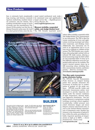
Emerson’s wireless field network
capital expenditure is relatively easy to justify at PPG installs easily and is up
and running in five minutes
W
ith the challenging global they perform, and it’s just a question to the maintenance staff or operations
marketplace and these un- of what scale they operate those in.” regarding whether a piece of equip-
stable financial times, the McAtee adds that because of the ment needs attention.
chemical process Industries variations from site to site, each “A setup that provides early identi-
(CPI) must do everything possible to chemical processing plant will have fication of potential performance prob-
economically maintain production a different set of tools and techniques lems usually results in a successful
while providing innovative and high in place. “I’m not aware of any facility maintenance practice,” says McAtee.
quality products for their customers. that has applied every type of mainte- Early identification of problems is
To achieve both these goals, predictive nance tool to every plant or the same key to predictive and preventive main-
and preventive maintenance programs tools in every plant and successfully tenance practices, which are crucial in
are possibly the most important gear kept it in place. This isn’t necessary to today’s economy because they turn
in any processors toolbox. yield efficient results.” maintenance from a reactive effort
Not only will performing predictive What is necessary, however, is a into a more proactive one where prob-
and preventive maintenance tasks on strong foundation for predictive and lems are spotted early and corrected
at least critical process equipment preventive maintenance. “No matter during planned maintenance intervals
help extend the life of those assets and what discipline of the chemical pro- during slow production times.
reduce capital spending, but it will cessing industry, the maintenance “It’s important for chemical pro-
also reduce downtime, which leads team has to have a solid framework to cessors to operate their equipment
to greater production rates, and keep build upon,” McAtee says. Most start without any surprises and with mini-
machinery running to specification, with a Computerized Maintenance mal possible maintenance costs. Un-
which helps ensure product quality. Management System (CMMS) that planned and unscheduled work tends
However, while all industrial facili- serves as the base for data capture, to be two to four times as expensive as
ties require maintenance in order to work planning and scheduling, mate- planned maintenance work,” explains
keep on running, the CPI have a few rials management and repair history. Bart Winters, reliability solution man-
unique challenges, including a com- “From our perspective, the CMMS is ager with Honeywell Process Solutions
plex and diverse set of operations in the foundation that leverages any (Morristown, N.J.) “For this reason,
any one facility. of the other more sophisticated pre- the goal of most chemical processors
“There may be differences of com- dictive and preventive maintenance is to operate from planned shutdown
plex chemical synthesis with very tools,” notes McAtee. to planned shutdown without any un-
specialized equipment and significant The CMMS should be combined planned downtime in between.”
variations of scale from small bioreac- with tools and field devices that moni- This goal is especially important
tor systems up to enormous ethylene tor and analyze the health of critical during a time when raw material costs
manufacturing units, all with differ- equipment, such as instrumentation, are still on the rise and energy prices
ent unit operations in a single facility,” rotating equipment and fixed or large are fluctuating, according to Scott Ho-
explains Michael McAtee, senior vice assets. The data from these tools, he keness, business development man-
president of engineering and main- says, should be tied into a centralized ager of the Asset Optimization Divi-
tenance for BASF Corp. (Florham database that allows all the field con- sion of Emerson Process Management
Park, N.J.). “Other industries, such as ditions and information to be analyzed (Austin, Texas). For this reason, now
[petroleum] refineries tend to have a more effectively and provides trend is the time chemical processors should
fairly small slate of unit operations analysis, as well as suggestions back be looking into leveraging new tech-
20 Chemical Engineering www.che.com January 2009
08_CHE_011509_NF2.indd 20 12/18/08 12:57:23 PM](https://image.slidesharecdn.com/chemicalengineering200901-130204110322-phpapp02/85/CSTRs-Bound-for-Maximum-Conversion-22-320.jpg)


![Cover Story
Feature Report
CSTRs: Bound for
Maximum Conversion
Ralph Levine Here, a design approach for
Retired
continuous stirred-tank reactors
M
ultiple CSTRs (continuous
stirred-tank reactors) are
is outlined for both reversible
advantageous in situations
where the reaction is slow; two
and irreversible second-order reactions
immiscible liquids are present and re-
quire higher agitation rates; or viscous ond-order reaction, at constant volume Reactor volume. The case for CSTRs
liquids are present that require high and temperature, are represented by at constant volume and temperature
agitation rates. Unlike in plug-flow re- Equation (1). The reaction is illustrated is shown in Equation (6).
actors, agitation is easily available in below (nomenclature defined on p. 34).
CSTRs. In this article, analyses of batch
and plug-flow reactors are calculated
(6)
and compared to multiple CSTRs.
(1)
The number of reactors required in
a CSTR system is based on the conver- (2a) (6a)
sion for each stage. When the final stage
(2b) Substituting Equation (6a) into (6)
obtains the fraction of unconverted re-
and rearranging gives Equation (6b).
actant that is equal to the desired final Here, M = CD0/CB0 for M 1.0.
value from the plug-flow case, the CSTR Conversion at the final desired con-
system is complete. centrations is defined by Equations (2a)
The volumetric efficiency of multiple and (2b). Substituting these equations (6b)
CSTRs is expressed as a function of at any conversion level into Equation
conversion per stage and gives the total (1) gives the following expression. Based on Equation (6a), we can find
conversion required. In this article, we the reaction rate for any stage, as
will apply this to both irreversible and (3) shown in Equations (7a)–(7c).
reversible second-order reactions. The ideal plug-flow case is given by
Equation (4). The batch case may also (7a)
2nd-order, irreversible reaction be evaluated by this equation, because
For a two-component system reacting batch reaction time t is equal to (V/v) (7b)
irreversibly, design of a CSTR series for plug-flow.
requires knowledge of the following: the (7c)
volumetric efficiency of the reactor based The second reactor in a series of CSTRs
on the order of the reaction, the number (4) is of equal volume to the first reactor.
of stages, and the conversion in the first Therefore, the conversion is X1 = X2, as
stage. The initial ratio of one component given in Equation (8).
to the other may be greater than one. (4a)
The reactor design is developed by
first selecting a conversion in the first Substituting Equation (3) into Equa-
stage. Then, the second-stage conver- tion (4), and integrating the resulting (8)
sion is equal to that of the first stage, Equation (4a), gives Equation (5). The third stage is also the same vol-
since it requires an equal volume. This ume, so the conversion is X1 = X3 as
procedure is continued until the frac- given in Equation (9).
tion of reactant remaining equals the (5)
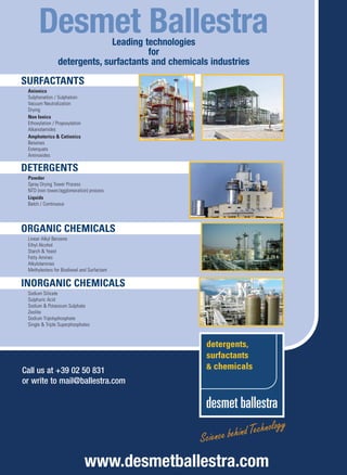
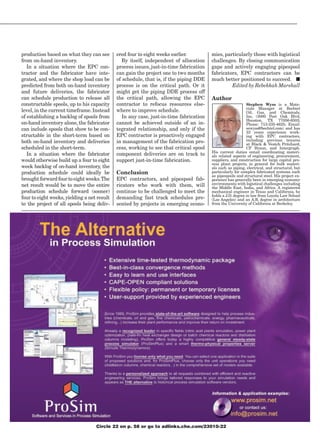
desired value. Reactors may be stacked,
one above the other, to reduce the over- When M = 1.0, second-order kinetics
all cost (Figure 1). as given in one of the author’s earlier (9)
The kinetics of a bimolecular or sec- articles can be used [3]. It can be shown that the nth reaction
30 Chemical Engineering www.che.com January 2009
14_CHE_011509_KT.indd 30 12/23/08 11:17:27 AM](https://image.slidesharecdn.com/chemicalengineering200901-130204110322-phpapp02/85/CSTRs-Bound-for-Maximum-Conversion-56-320.jpg)
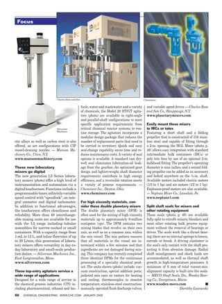
![1.0
CBf = CBn
CBf CDf
Volumetric efficiency V/VT
CBn CDn CDf = CDn 0.8
0.6
CB(n-1) - CBn
Xn =
CB(n-1)
0.4
CBn-1 CDn-1
0.3
0.2
CB1 - CB2 0.2 0.4 0.6 0.8 1.0
X2 = Conversion ratio X1/Xe
CB1
n = No. of steps
10 7 5 4 3 2
1.0
CB1 CD1 0.8
CB0 - CB1 0.6
X1 =
CB0
[1-(X1/Xe)]
0.4
At 80% equlilbrium
CBo CDo conversion totally
0.3
CBo CDo
0.2
CBo - CBf CDo/CBo = M 1.0 Product:
Xf =
CBo CPf and CSf
Plug-flow Multiple backmixed
reactor reactors
0.1 0.2 0.3 0.4 0.5 1/n
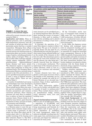
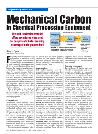
Figure 1. Conversion in plug-flow reactors and CSTRs for Figure 2. These graphs represent the calculations performed in
second order reactions is shown here, with conversion per Table 3. They illustrate the volumetric efficiency as a function of
stage shown for the CSTR case conversion ratio (top), and [1–(X1/Xe)] as a function of 1/n (bottom)
is given by Equation (10) and the final effect is 1.0988, as shown in theright-
stage is given as (10a). hand column of Table 1. Meanwhile,
Table 2 shows the calculation progres-
sion for the CSTR volume effect (the
(10) (11a) bottom half of Equation [11]) with
the complete term represented in the
high-hand column. In order to find the
(10a) Simplify Equation (11), noting that volumetric efficiency, the final CSTR-
(M–Xf) = (M–1)+(1–Xf). volume term, X1/[(1–X1)(M–X1)] must
The volume of each stage is dependent be equal to or higher than the final
on the conversion in the first stage, as value for the volume in plug-flow.
in Equation (6a), for any value of v, k, 1. f we select X1 = 0.5 (50%), three
l
CB0, and M. stages are required. The volumetric
Volumetric efficiency. The volumet- efficiency for this CSTR series is:
ric comparison for plug-flow or batch V/VT = 1.099/1.185 = 0.927
reactors to the series of CSTRs is called 11b)
( 2. n the case where X1 = 0.4 (40%)
I
“volumetric efficiency,” as shown below. Tables 1 and 2 for plug-flow reactors conversion, 6 stages are required.
show the calculations involved in The volumetric efficiency is:
Equation (11b) for various values of V/VT = 1.099/1.139 = 0.965
final conversion. At high conversions, 3. he next case, where X1 = 0.35 (35%)
T
the volume of the reactor should be conversion, 9 stages are required.
Divide Equation (5) by Equation (10a) larger, assuming a constant flowrate The volumetric efficiency here is:
to calculate the volumetric efficiency. for each case. The volume required is V/VT = 1.099/1.129 = 0.973
calculated using Equation (5). 4. he last case to consider is where
T
For CSTRs in series, one of several X1 = 0.6 (60%) conversion. Here, 2
cases of conversion for a series of reac- stages are required. The volumetric
tor stages may be selected. Each stage efficiency for this case is:
must contain the same volume to ob- V/VT = 1.099/1.465 = 0.750
tain the same conversion (X1) in each. The preferred design is at X1 = 0.5
If we select a conversion of Xf = 0.8 (50%), where 3 stages are required.
(80%) and M = 2 mole ratio of D to B The comparison for 3 stages (at
(11) initially, then the plug-flow volume 50% conversion) to 6 stages (at 40%
Chemical Engineering www.che.com January 2009 31
14_CHE_011509_KT.indd 31 12/23/08 11:18:39 AM](https://image.slidesharecdn.com/chemicalengineering200901-130204110322-phpapp02/85/CSTRs-Bound-for-Maximum-Conversion-57-320.jpg)
![Cover Story
conversion) is: Table 1. Plug-flow, M = 2
0.927/0.965 = 96.1% (M–Xf)/ log[(M–Xf)/ 2.303xlog[(M-
For 3 stages versus 9 stages at 35% M–Xf 1–Xf (1–Xf)M (1–Xf)M] Xf)/(1–Xf)M]
conversion, volumetric efficiency is: 1.2 0.2 3.000 0.477 1.099
0.927/0.973 = 95.3%
1.25 0.25 2.400 0.398 0.917
This means that we lose less than
5% of the volumetric efficiency at the 1.3 0.3 2.167 0.336 0.773
increase of more stages, making a 1.35 0.35 1.928 0.285 0.657
three-stage CSTR series an efficient 1.4 0.4 1.750 0.243 0.560
choice for this reaction. 1.5 0.5 1.500 0.176 0.406
Table 1. Here, calculations are performed to find the plug-flow volume effect, as de-
2nd-order, reversible reaction termined using Equation (11). The 1/(M-1) term in this case is equal to 1
A kinetic process that depends on two
components for a reversible reaction Expressing reaction rate. The rate
may be designed by calculating the equation is modified to include conver- (17d)
conversion in the first stage; the num- sion and equilibrium constant terms.
ber of stages of equal volume; and the Substituting Equations (12a)–(14d) Stirred reactor in a batch or plug-
volumetric efficiency of the reactor. into (12) gives Equation (15a). flow reactor. The batch reactor case
The initial ratio for the two compo- and the ideal continuous plug-flow case
nents may be any value greater than are given in Equation (18).
1. However, a preferred ratio of 2 could The reaction time is t for the batch
simplify the reaction rates. case, or V/v for plug-flow case.
(15a)
B+D is to be converted to P+S. The
kinetic rate expression of a reversible (18)
bimolecular reaction is given as Equa-
tion (12) at constant temperature and (15b) Substituting Equation (17d) into (18)
volume for each stage. At equilibrium, the reaction rate gives Equations (18a) and (18b).
equals zero.
(12)
(12a) (16a)
(18a)
(13a)
(13b) (16b)
Here, M = CD0/CB0 1 mole ratio. (18b)
Equations (14a) and (14b) relate the Volume of each CSTR stage. An ex-
initial concentration of B to the final (16c) pression for the first stage of a CSTR
concentrations of the P and S for a given Using the quadratic equation, Equa- is given in Equation (19). The first-
final conversion, assuming that there is tion (16c) becomes (16d). stage conversion X1 occurs in each
no initial concentration of P and S. of the successive stages (X2, X3, and
so on), and each stage has the same
volume.
(14a) (16d)
Referring to Equation (15b), we can (19)
(14b)
combine terms. Substituting Equation (17d) into (19)
Assume that P and S compounds are and rearranging gives (19a).
not present in the feed components.
Therefore, CP0 and CS0 are equal to
zero, and the following expressions
(19a)
are true: (17a)
(14c)
(19b)
(17b)
(14d)
Equation (19b) has only one indepen-
(17c) dent variable (V). If each stirred reac-
(14e)
32 Chemical Engineering www.che.com January 2009
14_CHE_011509_KT.indd 32 12/23/08 11:19:13 AM](https://image.slidesharecdn.com/chemicalengineering200901-130204110322-phpapp02/85/CSTRs-Bound-for-Maximum-Conversion-58-320.jpg)
![Table 2. CSTR Stages at Conversion X1
X1 1-X1 (1-X1)(M-X1) n (1-X1)(M-X1)n X1/[(1-X1)(M-X1)]n
0.80 0.20 0.360 1 0.360 2.222
0.70 0.30 0.510 1 0.510 1.373
0.60 0.40 0.640 1 0.640 0.938 Substitute Equation (22b) into (23a)
0.60 0.40 0.640 2 0.410 1.465
to obtain (23b).
0.50 0.50 0.750 1 0.750 0.667
0.50 0.50 0.750 2 0.563 0.889
0.50 0.50 0.750 3 0.422 1.185
0.40 0.60 0.840 1 0.840 0.476
(23b)
0.40 0.60 0.840 2 0.706 0.567
0.40 0.60 0.840 3 0.593 0.675
0.40 0.60 0.840 6 0.351 1.139 (23c)
0.35 0.65 0.878 1 0.878 0.399 Continue this process for the nth stage
0.35 0.65 0.878 2 0.771 0.454
to obtain the following equations.
0.35 0.65 0.878 3 0.677 0.517
0.35 0.65 0.878 4 0.594 0.589
0.35 0.65 0.878 5 0.522 0.671
(24)
0.35 0.65 0.878 9 0.310 1.129
0.30 0.70 0.910 1 0.910 0.330
0.30 0.70 0.910 2 0.828 0.362
(24a)
0.30 0.70 0.910 5 0.624 0.481
0.30 0.70 0.910 7 0.517 0.581
0.30 0.70 0.910 10 0.389 0.770
0.30 0.70 0.910 15 0.243 1.235 (24b)
0.25 0.75 0.938 1 0.938 0.267 Total volume of all stages. Substi-
0.25 0.75 0.938 4 0.774 0.323 tute Equation (19b) into (25).
0.25 0.75 0.938 8 0.599 0.417
(25)
0.25 0.75 0.938 16 0.359 0.696
0.25 0.75 0.938 20 0.278 0.899
0.25 0.75 0.938 24 0.215 1.162
Table 2. This table shows the calculations performed to find the CSTR volume ef-
fect, as determined using Equation (11). The last row for each value of X1, which are (25a)
shown in bold, give the required number of stages for particular reactor conversion
Substitute Equation (24a) for n in (25a).
tor stage is to be of equal volume and divide by (21) to find Equation (22).
at a constant volumetric flowrate, then
the result is a constant conversion per
stage. That is, each stage, when at a
(22)
fixed set of conditions, has the same
conversion resulting from each stage,
expressed as: 25b)
(
(22a)
X1 = X2 = X3 ... = Xn
By definition, CBn = CBo(1–Xf), where
Number of stages. Conversion for Xf is the overall or total conversion in
(22b)
stage 1 is expressed by Equation (20). the nth stage or the final desired con-
C − CB1 The exit concentration, CB1, can be version of the plug-flow reactor. By the
X1 = B 0 calculated from Equation (22a). Also, method used to obtain Equation (22),
CB0
(20) the exit concentration from the sec- the following equation is similarly de-
The equilibrium conversion is based ond stage, CB2, can be calculated rived. Substitution of Equation (24b)
on the time needed to reach a reaction from Equation (23a), based on each into (25b) gives Equation (25c).
rate of zero, which may be calculated stage having the same volume and
by Equation (16d) or (21). conditions.
C − CBe
X e = B0
CB0
(21)
Subtract Equation (21) from (20) and (23a)
(25c)
Chemical Engineering www.che.com January 2009 33
14_CHE_011509_KT.indd 33 12/23/08 11:19:50 AM](https://image.slidesharecdn.com/chemicalengineering200901-130204110322-phpapp02/85/CSTRs-Bound-for-Maximum-Conversion-59-320.jpg)
![Nomenclature
Cover Story CB Concentration of component B,
moles/unit volume
CD Concentration of component D,
moles/unit volume
Table 3. Volumetric Efficiency for Equation (26a) F Molar flowrate
k Reaction velocity constant
K Overall reaction velocity constant
(26a) M Initial mole ratio of D/B
n Number of stages
r Reaction rate
X1/Xe Xe 1–(X1/Xe) log[1–(X1/Xe)] (V/VT)Xe V/VT t Reaction time
0.1 0.7 0.9 –0.046 0.948 1.355 V Reactor volume
v Volumetric flowrate
0.2 0.7 0.8 –0.097 0.893 1.275
X Conversion
0.3 0.7 0.7 –0.155 0.832 1.189 Subscripts
0 Refers to initial conditions
0.4 0.7 0.6 –0.222 0.766 1.095
1,2,3
Refers to first, second and third
0.5 0.7 0.5 –0.301 0.693 0.990 stages
e Refers to equilibrium conditions
0.6 0.7 0.4 –0.398 0.611 0.873 j Refers to any stage in the series
of reactor stages
0.7 0.7 0.3 –0.523 0.516 0.737
n Refers to the nth stage
0.8 0.7 0.2 –0.699 0.402 0.575 f Refers to the overall or final
conditions
0.9 0.7 0.1 –1.000 0.256 0.366
F Conditions for forward reaction
TABLE 3. For any ratio of conversion per stage to equilibrium conversion, this table R Conditions for reverse reaction
provides the corresponding volumetric efficiency, based on Equation (26a). T Refers to the total of all n stages
Volumetric efficiency. Since VT/v in Examples: reversible reaction. The is independent of initial concentra-
Equation (25c) is residence time, as desired final conversion at a constant tion, velocity and equilibrium con-
is V/v in Equation (18b) for CSTRs, volumetric conversion is related to the stants at constant temperature and
these terms are equivalent. The vol- number of stages required. The num- the final conversion desired. It is de-
umetric flowrate is the same in all ber of stages required can be obtained pendent on only the ratio of the first
cases (a batch operation for one com- by solving Equation (24a). stage conversion to the equilibrium
plete reaction cycle). Thus, the ratio With n stages in multiple reactors, conversion. ■
of comparison should be V for plug- the conversion per stage is calculated Edited by Kate Torzewski
flow or batch operation (reaction vol- from Equation (24a). Assume an over-
ume and time only) compared to VT all conversion of 80% of the equilib- References
for multiple CSTRs. This ratio (V/VT) rium conversion. A plot of (1–X1/Xe) 1. Levenspiel, O. “Chemical Reaction Engineer-
ing,” John Wiley Sons, Inc., 1962.
is expressed as Equation (26), as de- versus 1/n on semilog paper gives a
2. Levine, R., Hydro. Proc., July 1967, pp.
rived from (18b) and (25c). straight line, as seen in Figure 2 [3]. 158–160.
The variables needed to evaluate Refer to the volumetric efficiencies 3. Levine, R. A New Design Approach for Back-
mixed Reactors — Part I, Chem. Eng. July 1,
the volumetric efficiency are: the first in Table 3, which represents Equation 1968, pp. 62–67.
stage conversion; the number of reac- (26a). If we select a volumetric effi- 4. Levine, R. A New Design Approach for Back-
tor stages n; and the initial mole ratio ciency of 0.893, a plug-flow reactor will mixed Reactors — Part II, Chem. Eng. July
29, 1968, pp. 145–150.
of the excess reagent to the limiting have only 89.3% of the multiple CSTR 5. Levine, R. A New Design Approach for Back-
reagents, M. volume. The conversion in Table 3 is mixed Reactors — Part III, Chem. Eng. Aug
12, 1968, pp. 167–171.
about 20% conversion per stage. From
Figure 2 or Equation (24b), and a ratio
of conversion per stage compared to Author
equilibrium conversion or (1–X1/Xe) = Ralph Levine is a retired
chemical engineer currently
0.80, 7.14 stages is required. working as a consultant
This calculation can be performed in for plants, design or opera-
tions and RD (578 Arbor
reverse, if we would like to design the Meadow Dr., Ballwin, Mo.
CSTR series in four stages. From Fig- 63021; Email: ralphle2000@
yahoo.com). Levine earned
ure 2, we find that the term (1–X1/Xe) a B.S.Ch.E. from the City
(26) equals 0.67. Next, refer to Equation University of New York, and
did graduate work at Louisi-
(See Table 3) (26a) (26a) and Table 3 for the efficiency at ana State University and the
University of Delaware. Levine later served as
(X1/Xe), which equals 0.33, and finally an engineer for the U.S. Army Chemical Corps.
Equation (26a) is independent of ini- shows the volumetric efficiency of 81%. He has worked for DuPont, Cities Service Co.,
and most recently, Columbian Chemical Co.
tial or final concentrations and the Levine has filed several U.S. patents during his
velocity constant at constant tempera- Summary of conclusions career, and is a published author, with his work
featured in Chemical Engineering and Hydro-
ture, as well as of overall conversion. The volumetric efficiency in a CSTR carbon Processing.
34 Chemical Engineering www.che.com January 2009
14_CHE_011509_KT.indd 34 12/23/08 11:21:15 AM](https://image.slidesharecdn.com/chemicalengineering200901-130204110322-phpapp02/85/CSTRs-Bound-for-Maximum-Conversion-60-320.jpg)
![Feature Report
Controlling Emissions
With Ceramic Filters Table 1. Characteristics of High- and Low-Density
Ceramic-Filter Elements
Ceramic filters are well suited High density Low density
for high-temperature processes Structure
Density
Granular
High
Fibrous
Low
that are subject to Filter drag High Low
Porosity, % (inverse of resistance to flow) 0.3 – 0.4 0.8 – 0.9
strict emissions limits, Tensile strength High Low
including those for dioxins Fracture mechanism
Thermal shock resistance
Brittle
Low
Ductile
High
Cost High Low
Andrew Startin and Gary Elliott
Clear Edge Filtration
About incineration
C I
eramic filters offer practical installations. Of particular interest ncineration processes are being widely
operating benefits and com- are the emissions of dioxin chemicals used more and more to deal with the
mercial competitiveness in pol- and particulate matter that have been disposal of waste materials. In many
lution abatement applications under close scrutiny since the 1990s. countries, land filling of waste materials
where processes combine ele- Official emissions reports commis- is not practical or desirable due to a lack
vated-temperature off gases with the sioned for these plants indicate emis- of appropriate sites. Incineration has the
need for high levels of corrosion resis- sions well within regulated limits. benefit of reducing both the volume and
tance and the ability to eliminate dust mass of waste, thus reducing the amount
of material to be disposed of.
emissions. This article discusses the Ceramic filtration technology Incineration is now applied to a wide
applicability of ceramic filtration tech- The concept of using a refractory ce- range of waste streams from high-tonnage
nology, with focus on, and examples of ramic material to form a filter me- municipal solid waste (MSW) through to
its use in incineration processes. dium, predominantly for use at el- the lower-tonnage specialty wastes pro-
The ability to deliver low emissions, evated temperature (generally in the duced by industrial processes. However,
even with fine particles that are 2.5 region of 200–400°C, but can be up whatever the application, the imperative
micrometers (μm) or smaller (PM2.5), to 900°C) has been around for many for the incineration process is broadly the
while operating at an elevated tem- years [1]. One of the earlier forms same — a reduction in mass and volume
perature is the primary driver for of ceramic filter was devised for ad- while rendering the remaining waste mate-
the application of ceramic elements vanced power-generation applications rial as inert as possible and, of course, pro-
ducing the absolute minimum of emissions.
to high temperature processes that with the requirement for operation at
Waste incineration, as with other in-
are subject to strict emissions limits. high temperature and high pressure. dustrial processes, has been the subject
Such processes include metal smelt- In the form of flanged tubes, closed at of ever tightening emissions legislation
ing, chemicals production and waste one end, these “high density” media in recent years. Public disquiet over in-
incineration. In the latter case, ce- are still in widespread use across a cineration processes and the generation
ramic elements have been applied to broad range of applications. of potentially dangerous emissions has
a number of small- to medium-scale Low-density ceramic filter elements subsequently, detrimentally affected the
incineration duties including medical (hereafter referred to as ceramic ele- approval of many new installations. Con-
waste, soil cleaning, asphalt recycling, ments) were initially developed in the sequently, the industry has sought effective
industrial waste, chemical waste and middle 1980s. One of the first appli- post-incinerator processes for dealing with
off gases in terms of reducing and elimi-
building waste. cations for ceramic elements was in
nating emissions and where practical, re-
Several new, high-temperature in- thermal soil remediation. This process covering useful energy. Many techniques
cineration installations have been set involves driving off the volatiles from and combinations of techniques have been
up to deal with waste that is of mixed contaminated soil in a rotary furnace developed and are under development —
composition from various sources. Ce- to decontaminate it and make it reus- a broad overview of which is beyond the
ramic elements have been selected as able. The first stage in the complex scope of this paper. ❏
the filter medium for a number of these off-gas treatment train is high tem-
Chemical Engineering www.che.com January 2009 35
15_CHE_011509_DL.indd 35 12/22/08 10:28:47 AM](https://image.slidesharecdn.com/chemicalengineering200901-130204110322-phpapp02/85/CSTRs-Bound-for-Maximum-Conversion-61-320.jpg)


![Table 7. Honshu I emissions measured at the filter stack
on May 31, 2002
Item Unit Value
1) Dioxin ng-TEQ/Nm3 0.00032 Authors
Gary Elliott is the general
2) Dibenzofuran ng-TEQ/Nm3 0.02296 manager of Clear Edge Fil-
3) PCB ng-TEQ/Nm3 0.0000326 tration’s (formerly Madison
Filter) Cerafil Division (Clear
4) 1) + 2) + 3) ng-TEQ/Nm3 0.023 Edge UK Ltd., The Stable,
Rock Farm, Seckington, Tam-
5) Total particulate mg/Nm3 0.3 worth, B79 OLA, U.K.; Phone:
+44–1827–839125; Email:
6) HCl mg/Nm3 2 Gary.Elliott@clear-edge.com).
After graduating with a B.S.
7) SOx ppm 1 degree from Leicester Uni-
versity, Elliott worked in the
8) NOx ppm 120 field of high temperature ceramic in the metal-
9) CO ppm 0 lurgical field, and more recently in the field of
gas filtration. Elliott has specialized in applying
10) O2 % 10.6 ceramic filters to industrial gas filtration for pol-
lution control duties as well as for process filtra-
11) Moisture % 22.0 tion and product collection.
Wet Nm3/h 19,110 Andrew Startin is the prod-
12) Actual gas volume Dry Nm3/h 14,910 uct manager at Clear Edge
Filtration’s Cerafil Division,
13) Gas temperature oC (K) 188 (461) where he is responsible for
technical and business de-
velopment aspects of Cerafil.
He graduated in 1981 from
Table 8. Honshu II emissions measured at the filter stack Brunel University (London,
England) with a degree in ma-
on October 25, 2002 terials science and technology.
Item Unit Value3 Regulation3 From there, he joined Doulton
Industrial Products in Stone, Staffordshire where
1) Dioxin ng-TEQ/Nm3 he worked on projects developing industrial ce-
ramics primarily for the aerospace industry. He
2) Dibenzofuran ng-TEQ/Nm3 0.010 then joined Ashland Chemicals and followed by
Universal Abrasives where he was involved in
3) PCB ng-TEQ/Nm3 0.000010 further development work on technical and in-
dustrial ceramics. In 1990 Startin joined Foseco,
4) 1) + 2) + 3) ng-TEQ/Nm3 0.01 0.1 Birmingham, and first became involved with Cer-
afil ceramic filter elements in 1992. He became a
5) Total particulate mg/Nm3 0.1 250 full time member of the Cerafil team in 1994.
6) HCl mg/Nm3 45 700
Concentration ppm 28
7) SOx Emission Nm3/h 0.34 10.44
8) NOx ppm 100
9) CO ppm 0
10) O2 % 11.1
11) Moisture % 7.4
Wet Nm3/h 13,000
12) Actual gas
volume Dry Nm3/h 12,000
13) Gas temperature oC (K) 134 (407)
3. Empty cells mean either not measured or not regulated
Future developments hanced by the addition of a catalyst
Ceramic elements are employed in to the filter systems [2]. The catalyst
filter plants, either new or retrofitted, can reduce NOx with efficiency up to
in much the same way as traditional 95%, with the addition of ammonia or
polymeric filter bags. It has been dem- urea, and destroy VOCs as well as di-
onstrated that ceramic filters offer oxins. This new technology has poten-
practical operating benefits and com- tial for application where particulate
mercial competitiveness in high-tem- and NOx control are needed in tan-
perature processes where corrosion dem, and is competitive with electro-
resistance and the ability to eliminate static precipitators and standard se-
dust emissions are needed. lective catalytic reactors, particularly
A further important development in the power generation, glass and
of this technology has seen the in- cement industries. ■
troduction of ceramic filter elements Edited by Dorothy Lozowski
that not only deliver the dual benefits
References
of high particulate-removal efficiency 1. Ondrey, G., Some Filters Like it Hot, Chem.
and temperature resistance, but also Eng., November 2001, pp. 29–39.
treat gaseous pollutants. Fairly re- 2. Ondrey, G., Remove dust and pollutants
with this catalytic filter, Chem. Eng., July Circle 20 on p. 58 or go to
cently, these benefits have been en- 2005, p.16. adlinks.che.com/23010-XX
Chemical Engineering www.che.com January 2009 39
15_CHE_011509_DL.indd 39 12/22/08 10:31:28 AM](https://image.slidesharecdn.com/chemicalengineering200901-130204110322-phpapp02/85/CSTRs-Bound-for-Maximum-Conversion-65-320.jpg)


This document summarizes an article from the January 2009 issue of Chemical Engineering magazine. It discusses how the chemical process industries are facing a deep recession due to plant closings and layoffs. While the situation is sour, the article provides a few recommendations that could help sweeten the situation. These include strategic capital investments, predictive maintenance programs, and industrial wireless technologies, which can improve performance and reduce costs. The article also notes that now may be a good time for longer-term projects that require plant shutdowns due to reduced demand and lower equipment costs.


