Download to read offline


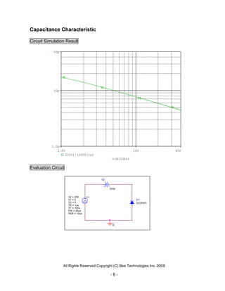


The document is a device modeling report for a Toshiba diode, specifically the CRH01 rectifier. It includes detailed specifications, PSpice model parameters, and various circuit simulation results, including forward current characteristics, capacitance characteristics, and reverse recovery characteristics. The report emphasizes the accuracy of simulation results compared to measurements, with minimal error margins.


