Download to read offline


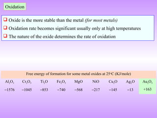
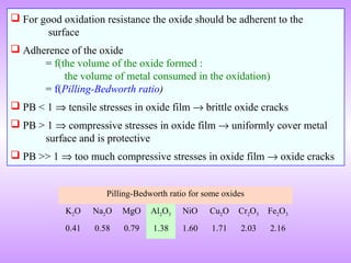
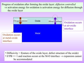


The document discusses corrosion and oxidation of metals, including the principles behind corrosion and methods for preventing corrosion. It describes how metals oxidize when exposed to oxygen and how the formation and properties of metal oxides, such as their adherence and volume, influence corrosion rates. Factors that affect oxidation rates and the development of protective oxide layers are covered. Methods for improving corrosion resistance through alloying and the use of coatings or inhibitors are also summarized.


