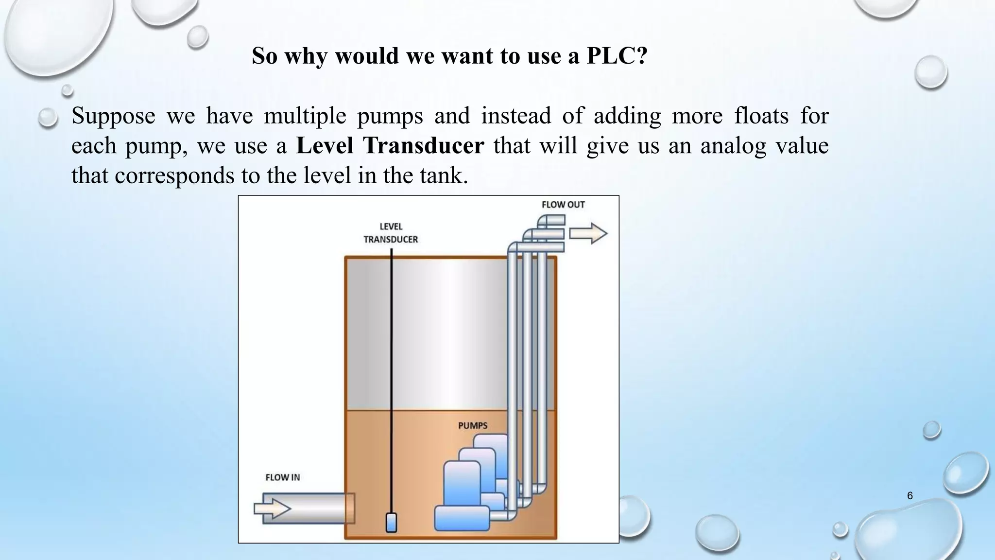
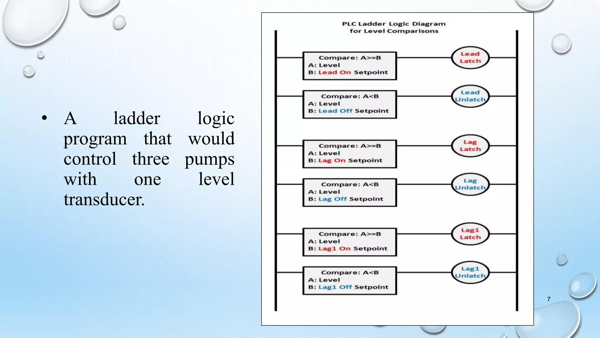
CONTROL OF WATER
PUMP USING PLC
PRESENTED BY :
JAYSHALINI-R16EE066
GANAVI M-R17EE052
AKSHATHA M VATRADA-
R17EE015
GHOUSIA SAMDHANI-
R17EE053
HARSHITHA CV-R17EE058
1
CONTENT
• CONTROL USING RELAY
CIRCUIT
• CONTROL USING PLC
• ADVANTAGES OF USING PLC
2
Here, a pump which is turned on and off using float switches
to maintain the level of a tank that has process water flowing
into it.
3
Simple ladder diagram that will control the pump
4
• As the level in the tank increases, it activates the "Off Float" first, but
nothing happens. Then, as the level continues to increase, the "On
Float" is activated which completes the circuit to the "Relay", turning
on the "Pump Starter".
• With the Pump on, the level decreases and drops below the "On Float",
but the "Pump Starter" remains on because the "Relay" is latched by the
relay contact until the "Off Float" breaks the latch, turning off the relay,
which turns off the starter.
• Then the level increases and the cycle is repeated.
This is a very simple pump control application that has been used for
decades.
A PLC is not required because a simple relay control circuit would be
sufficient. 5
So why would we want to use a PLC?
Suppose we have multiple pumps and instead of adding more floats for
each pump, we use a Level Transducer that will give us an analog value
that corresponds to the level in the tank.
6
• A ladder logic
program that would
control three pumps
with one level
transducer.
7
• The level signal is wired to an Input Module of the
PLC, and the Pump Starters are wired to a Output
Module.
• The analog signal from the level transducer (4–20mA) is
converted to a floating point value in the PLC’s memory
and then compared to a series of setpoints for the various
ON/OFF levels that are desired.
• The setpoints are level values that are entered using the
Operator Interface or SCADA computers.
• If the level of the tank is between the setpoints values for
Lead, Lag or Lag1, then the associated latch coils are
turned on.
8
• The pumps are
controlled with
additional logic,
like whether each
pump is in “Auto”
or “Manual”.
9
ADVANTAGES
• All ladder logic is programmed into the PLC using software, so hard-
wired logic is unnecessary. Changes to the logic can be made easily
without re-wiring.
• Dozens (or even hundreds) of Inputs and Outputs can be connected to
allow monitoring of instrumentation and controlling any kind of
process.
• Modular design for easy expansion.
• Variable Frequency Drives can be controlled directly to vary the speed
of pumps.
• Ethernet devices can be networked together so the process can be
graphically visualized and controlled via an Operator Interface and
SCADA database for historical trending and reporting. 10
11
REFERENCE
• Multiple pump : https://papapump.com/multi-pump
• Application : www.waterpoweredtechnologies.com
THANK YOU
12

Contol of water pump using plc

  • 1.
    CONTROL OF WATER PUMPUSING PLC PRESENTED BY : JAYSHALINI-R16EE066 GANAVI M-R17EE052 AKSHATHA M VATRADA- R17EE015 GHOUSIA SAMDHANI- R17EE053 HARSHITHA CV-R17EE058 1
  • 2.
    CONTENT • CONTROL USINGRELAY CIRCUIT • CONTROL USING PLC • ADVANTAGES OF USING PLC 2
  • 3.
    Here, a pumpwhich is turned on and off using float switches to maintain the level of a tank that has process water flowing into it. 3
  • 4.
    Simple ladder diagramthat will control the pump 4
  • 5.
    • As thelevel in the tank increases, it activates the "Off Float" first, but nothing happens. Then, as the level continues to increase, the "On Float" is activated which completes the circuit to the "Relay", turning on the "Pump Starter". • With the Pump on, the level decreases and drops below the "On Float", but the "Pump Starter" remains on because the "Relay" is latched by the relay contact until the "Off Float" breaks the latch, turning off the relay, which turns off the starter. • Then the level increases and the cycle is repeated. This is a very simple pump control application that has been used for decades. A PLC is not required because a simple relay control circuit would be sufficient. 5
  • 6.
    So why wouldwe want to use a PLC? Suppose we have multiple pumps and instead of adding more floats for each pump, we use a Level Transducer that will give us an analog value that corresponds to the level in the tank. 6
  • 7.
    • A ladderlogic program that would control three pumps with one level transducer. 7
  • 8.
    • The levelsignal is wired to an Input Module of the PLC, and the Pump Starters are wired to a Output Module. • The analog signal from the level transducer (4–20mA) is converted to a floating point value in the PLC’s memory and then compared to a series of setpoints for the various ON/OFF levels that are desired. • The setpoints are level values that are entered using the Operator Interface or SCADA computers. • If the level of the tank is between the setpoints values for Lead, Lag or Lag1, then the associated latch coils are turned on. 8
  • 9.
    • The pumpsare controlled with additional logic, like whether each pump is in “Auto” or “Manual”. 9
  • 10.
    ADVANTAGES • All ladderlogic is programmed into the PLC using software, so hard- wired logic is unnecessary. Changes to the logic can be made easily without re-wiring. • Dozens (or even hundreds) of Inputs and Outputs can be connected to allow monitoring of instrumentation and controlling any kind of process. • Modular design for easy expansion. • Variable Frequency Drives can be controlled directly to vary the speed of pumps. • Ethernet devices can be networked together so the process can be graphically visualized and controlled via an Operator Interface and SCADA database for historical trending and reporting. 10
  • 11.
    11 REFERENCE • Multiple pump: https://papapump.com/multi-pump • Application : www.waterpoweredtechnologies.com
  • 12.