Site selection and site plan
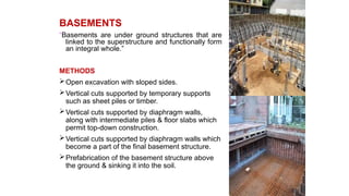
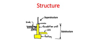
Foundation and basements
Masonry, Brick masonry, Stone masonry, Concrete hollow block masonry
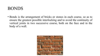
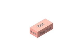
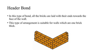
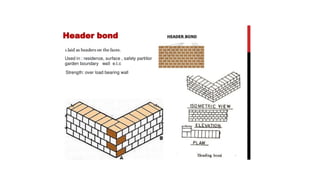
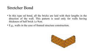
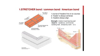
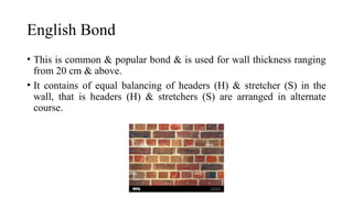
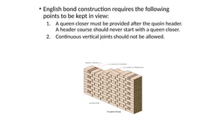
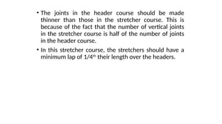
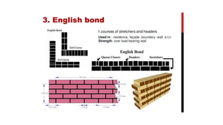
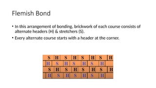
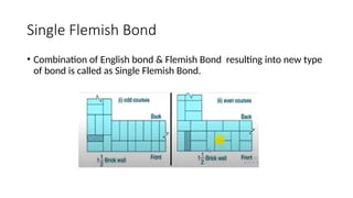
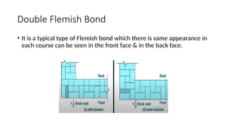
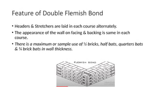
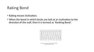
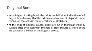
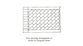
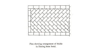
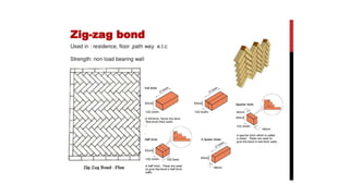
Bonds
Precast paver blocks
Flooring, Construction joints, Movement and expansion joints, Contraction joints
Form works, Centering and shuttering, slip forms, Scaffoldings, shoring and underpinning
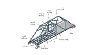
Fabrication and erection of trusses,
Acoustics, Sound insulation, Fire protection
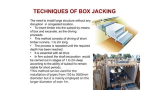
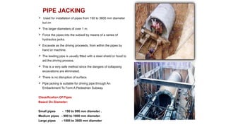
Box jacking, Pipe jacking, Arch jacking
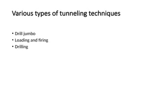
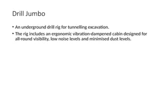
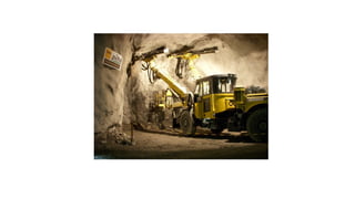
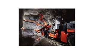
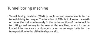
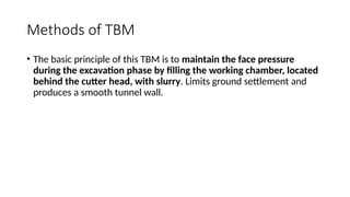
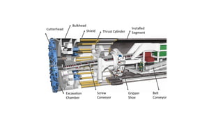
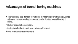
Tunnelling techniques
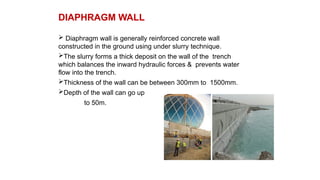
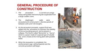
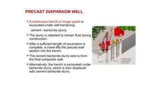
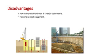
Underground and underwater diaphragm walls, Piling techniques
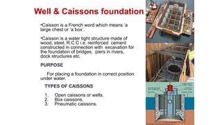
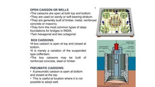
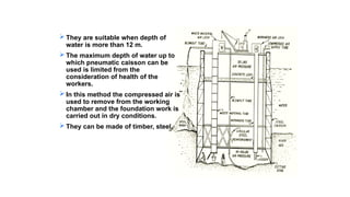
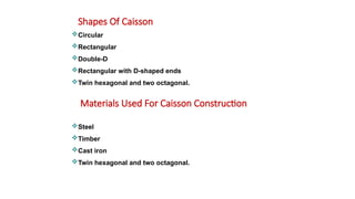
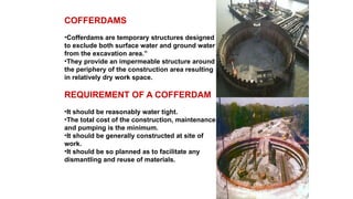
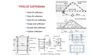
Well foundation and caisson
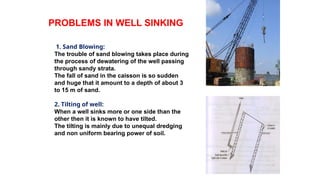
Sinking operations
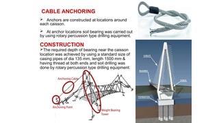
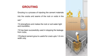
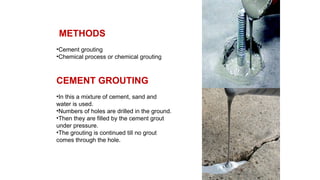
Cable anchoring and grouting
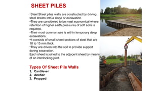
Sheet piling
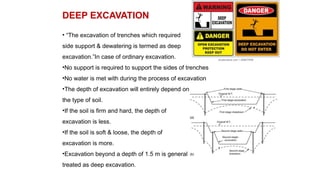
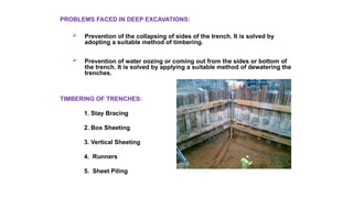
shoring for deep cutting
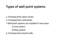
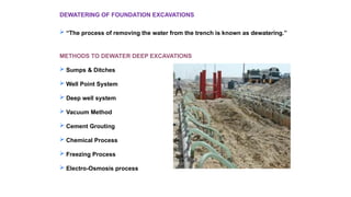
Dewatering techniques and pumping equipment
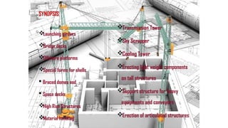
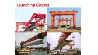
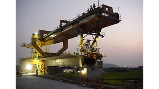
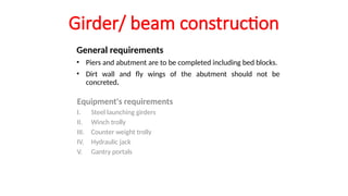
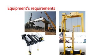
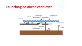
Launching girders
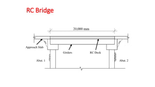
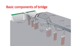
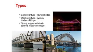
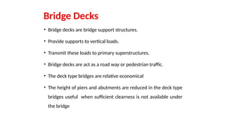
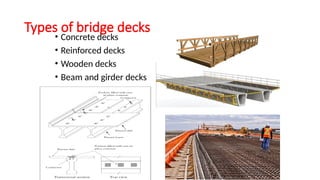
Bridge decks,
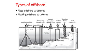
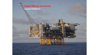
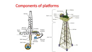
Offshore platforms
Special forms of the shells & domes
Techniques for heavy decks, In-situ prestressing in high rise structures
Material handling and erecting light weight components on tall structures
Articulated structures
Braced domes
Space decks