This document provides a user guide for managing connectors using the Connector Management module in ArcSight Express. It describes how to navigate the user interface to manage locations, hosts, containers, and connectors in a hierarchical structure. It provides instructions for common management tasks like adding, editing, deleting, moving, and upgrading different components of the connector architecture. Special configurations for certain connector types are also covered.


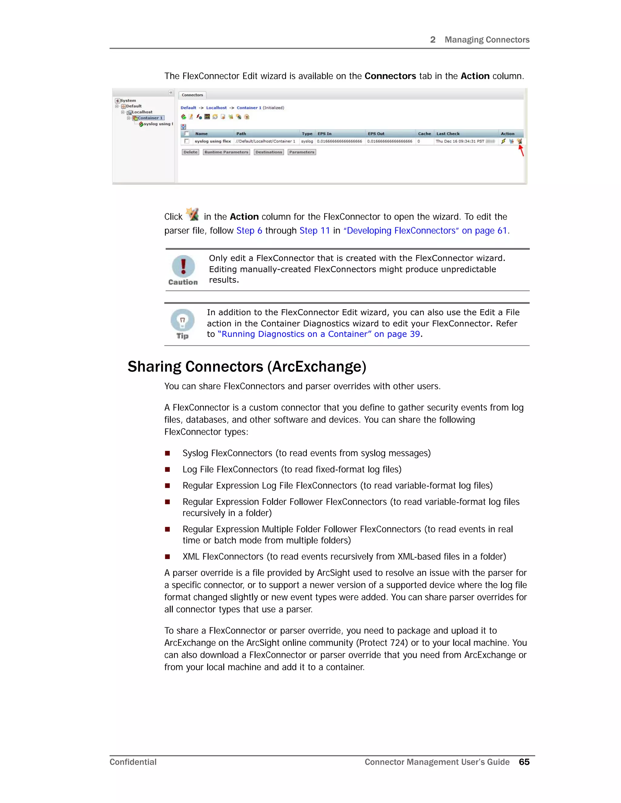
![2 Managing Connectors
Confidential Connector Management User’s Guide 73
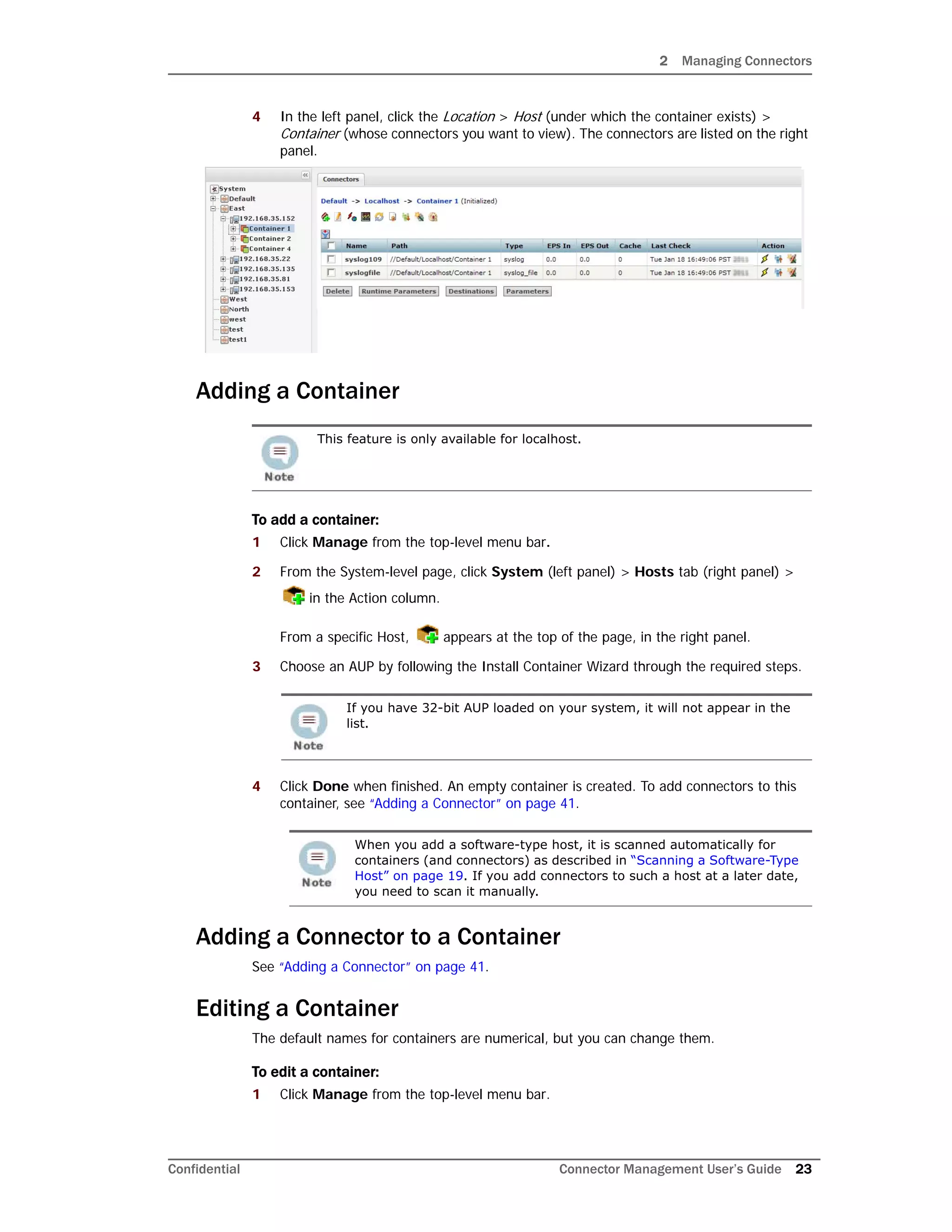
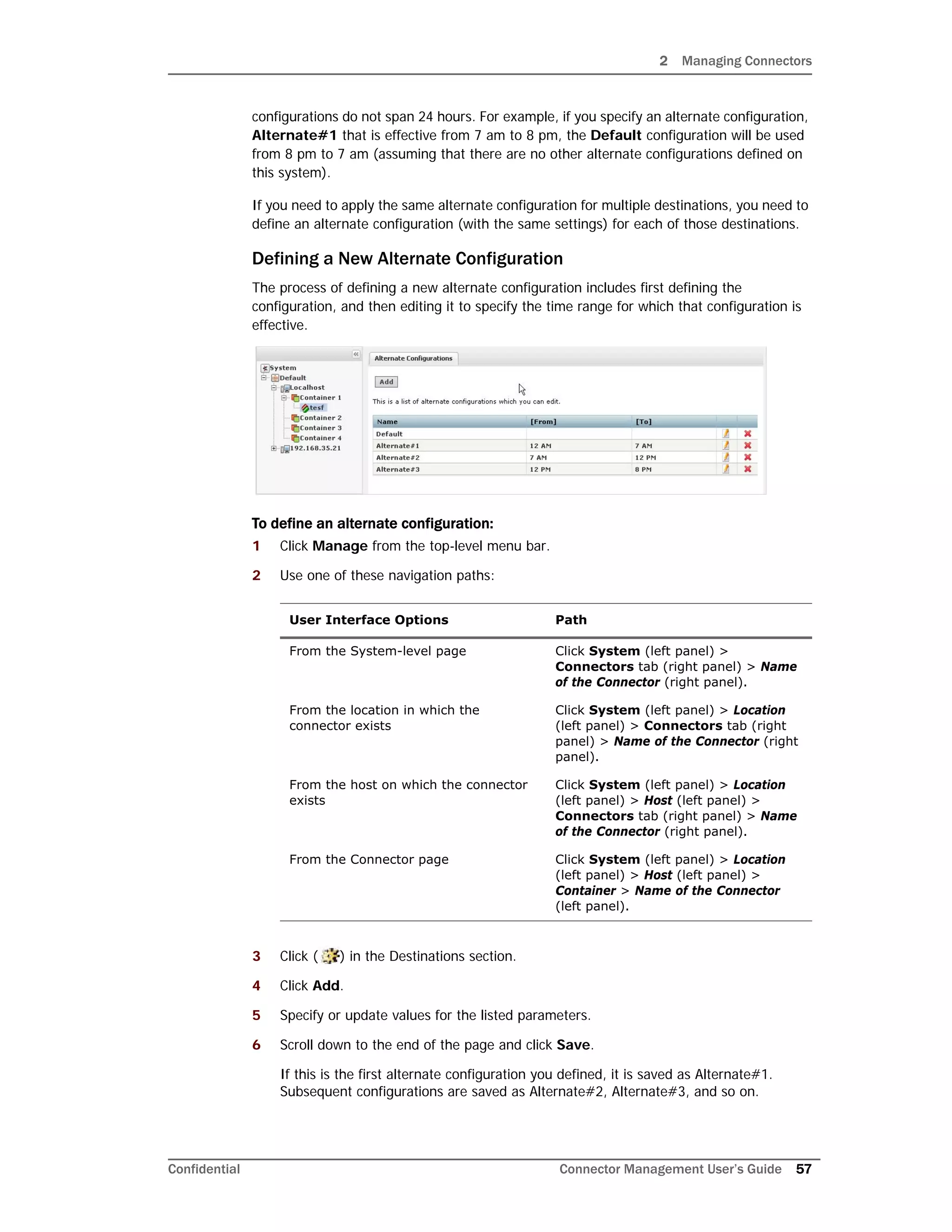
5 An error similar to the following is displayed.
-1:[X] Unable to connect to the Lea Server[10.0.101.185] -1:1
connection test failed!
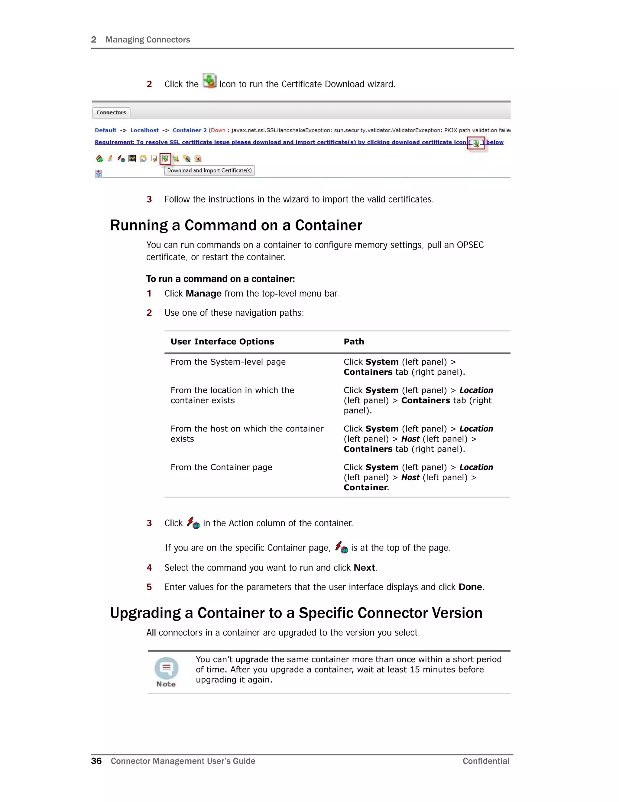
Click the Ignore warnings check box. Click Next.
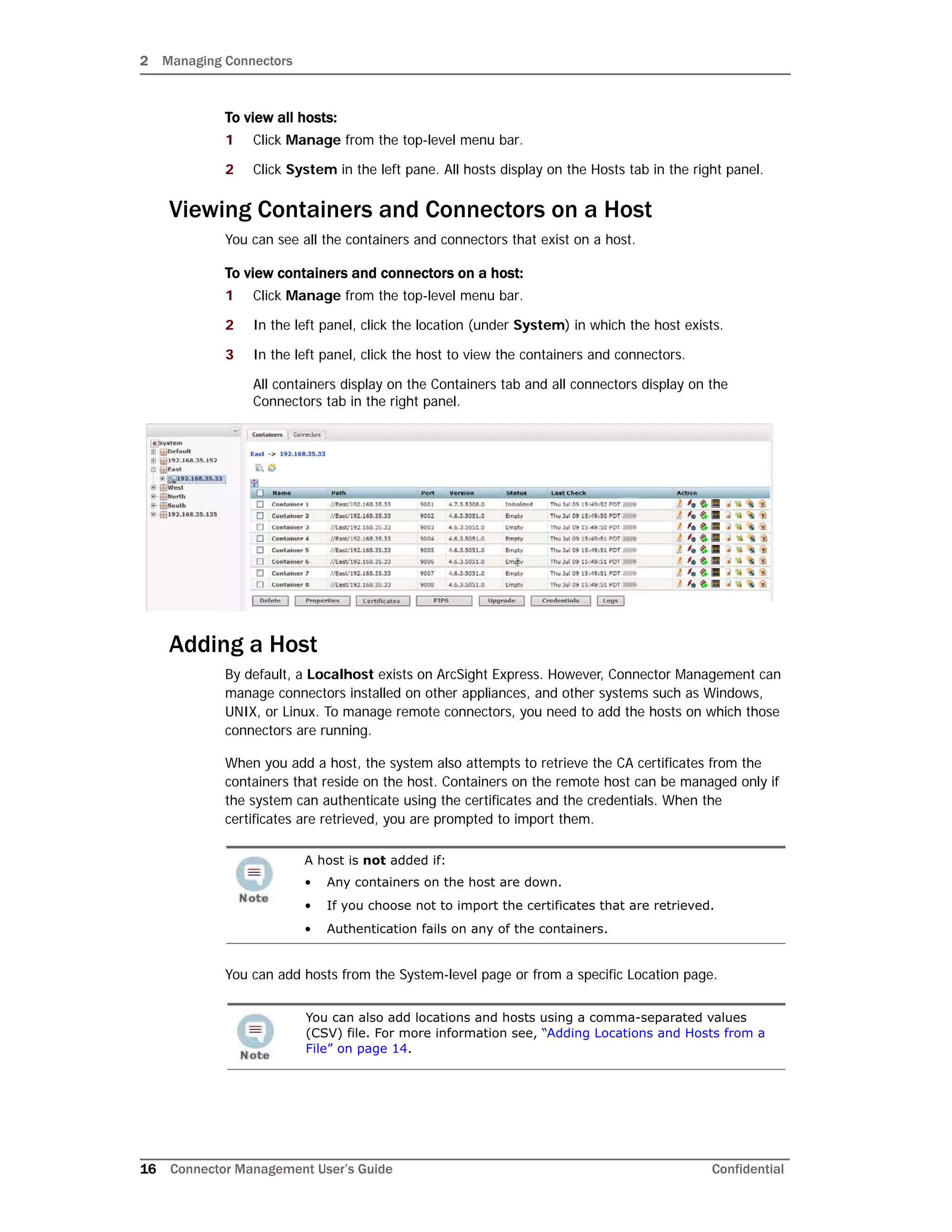
6 Continue to configure the rest of the connector. Go to Step 6 in “Adding a Connector”
on page 41.
Adding the MS SQL Server JDBC Driver
When you install and configure database connectors that use Microsoft SQL Server as the
database, a JDBC driver is required. This driver does not ship pre-installed on the system;
you need to install it before configuring database connectors on the appliance.
To install a JDBC Driver:
1 Download the MS SQL Server JDBC Driver to a computer that can access ArcSight
Express. You can download the driver from Microsoft at:
http://msdn.microsoft.com/en-us/sqlserver/aa937724
2 Run the setup program to install the driver.
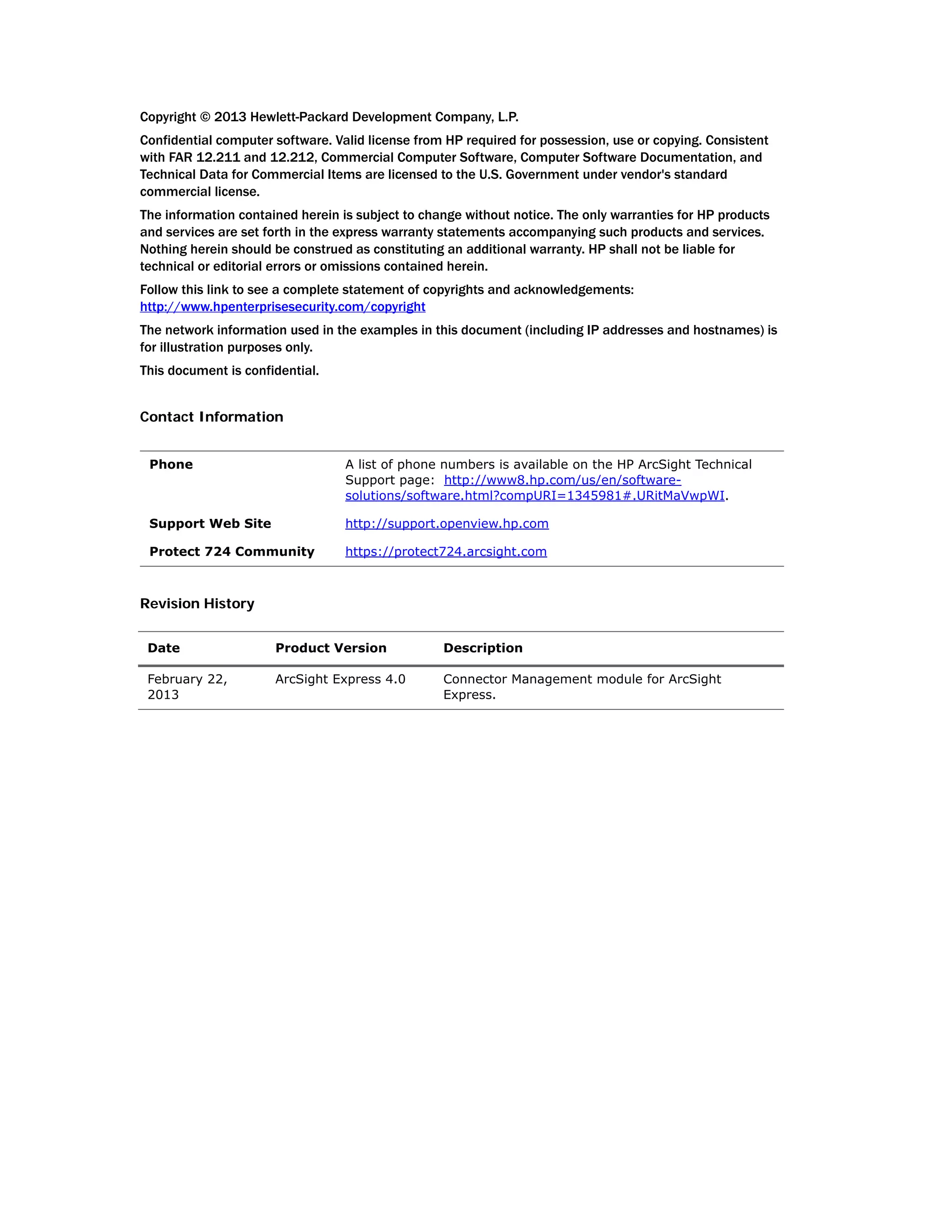
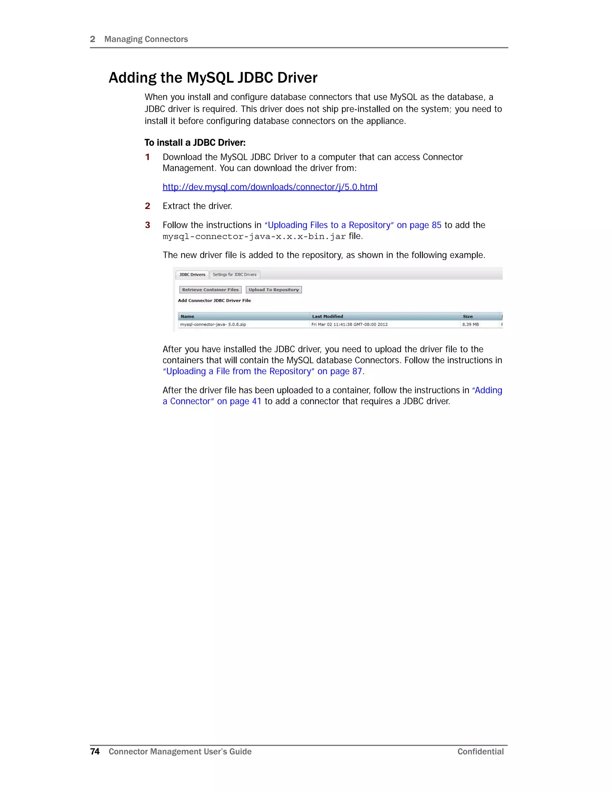
3 Follow the instructions in “Uploading Files to a Repository” on page 85 to add the
sqljdbc.jar file.
The new driver file is added to the repository, as shown in the following example.
After you have installed the JDBC driver, you need to upload the driver file to the
containers that will contain the SQL Server database Connectors. Follow the
instructions in “Uploading a File from the Repository” on page 87.
After the driver file has been uploaded to a container, follow the instructions in “Adding
a Connector” on page 41 to add a connector that requires a JDBC driver.
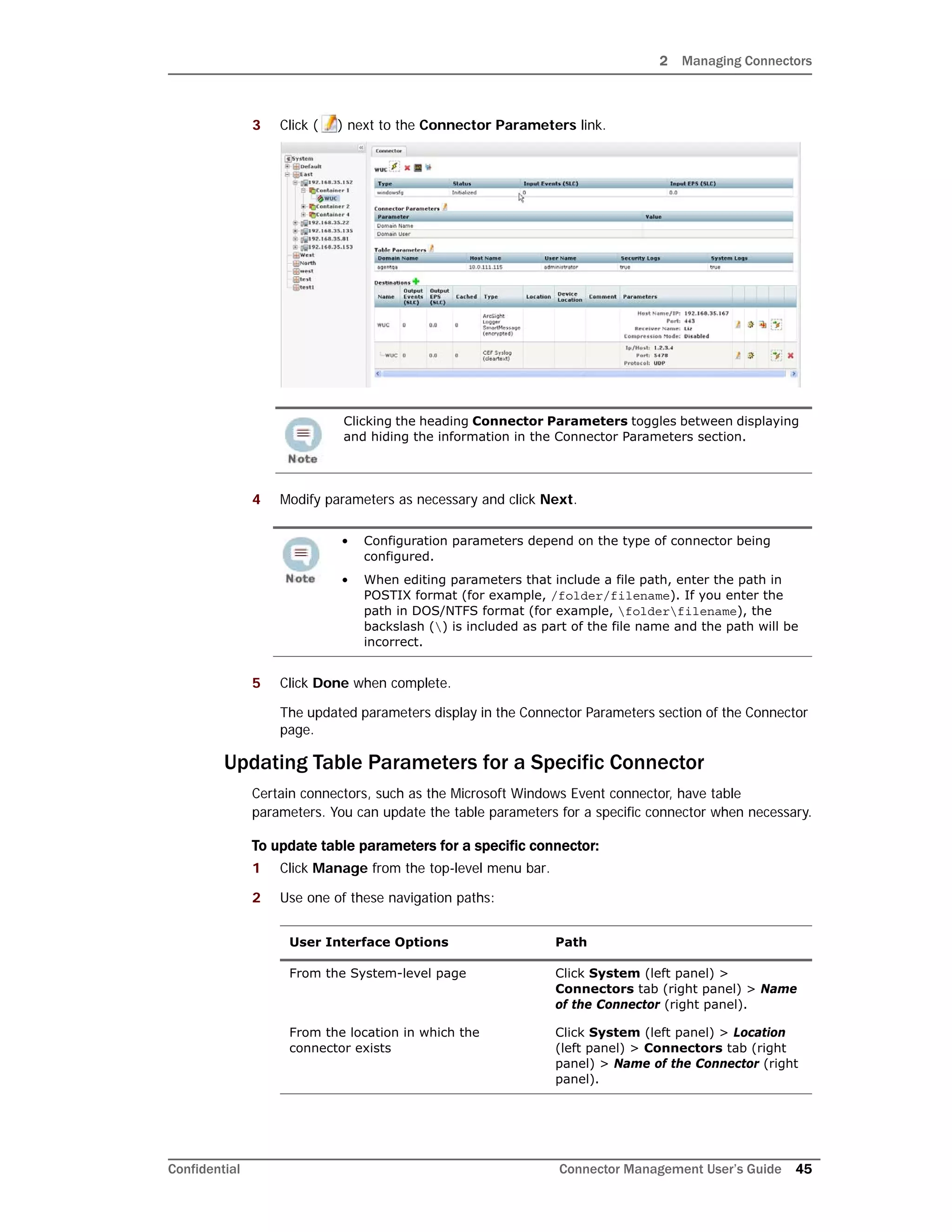
Connector
Table
Parameters
Server IP: The IP address of the Check Point server.
Server Port: The port on the server that listens for SSLCA
connections. Use the default value 18184.
OPSEC SIC Name: The name you noted in Step 1.
OPSEC SSLCA File: The name you noted after pulling the
certificate in Step 2.
OPSEC Entity SIC Name: The name you noted in Step 1.
The name of the jar file may be different from that of some JDBC driver
versions. Different versions of the JDBC driver are required for different SQL
Server database versions; be sure to use the correct driver for your
database.
Parameters Values to input](https://image.slidesharecdn.com/connappadminguideae4-170530064024/75/Connector-Management-User-s-Guide-for-ArcSight-Express-v4-0-73-2048.jpg)
![3 Managing Repositories
80 Connector Management User’s Guide Confidential
Content AUP Repository
ArcSight continuously develops new connector event categorization mappings, often called
content. This content is packaged in ArcSight Update Packs (AUP) files. All existing content
is included with major product releases, but it is possible to stay completely current by
receiving up-to-date, regular content updates through ArcSight announcements and the
Customer Support site. The AUP files are located under Content Subscription Downloads.
The ArcSight Content AUP feature enables you to apply an AUP file to applicable connector
destinations that you are managing. Only the event categorization information can be
applied to the connectors using this feature.
You can maintain a number of Content AUP files in the Content AUP repository. When an
AUP file with a version number higher than the ones already in the repository is loaded, it
is automatically pushed out to the connector destinations being managed. However, these
connectors or connector destinations are skipped:
Connectors that are unavailable at the time of the AUP file push
Connectors whose current version does not fall in the range of versions that the
Content AUP supports
The ESM destination on a connector
All destinations of a connector that have an ESM destination with the AUP Master flag
set to Yes
Also, when a new connector is added, the highest number Content AUP is pushed
automatically to its destinations.
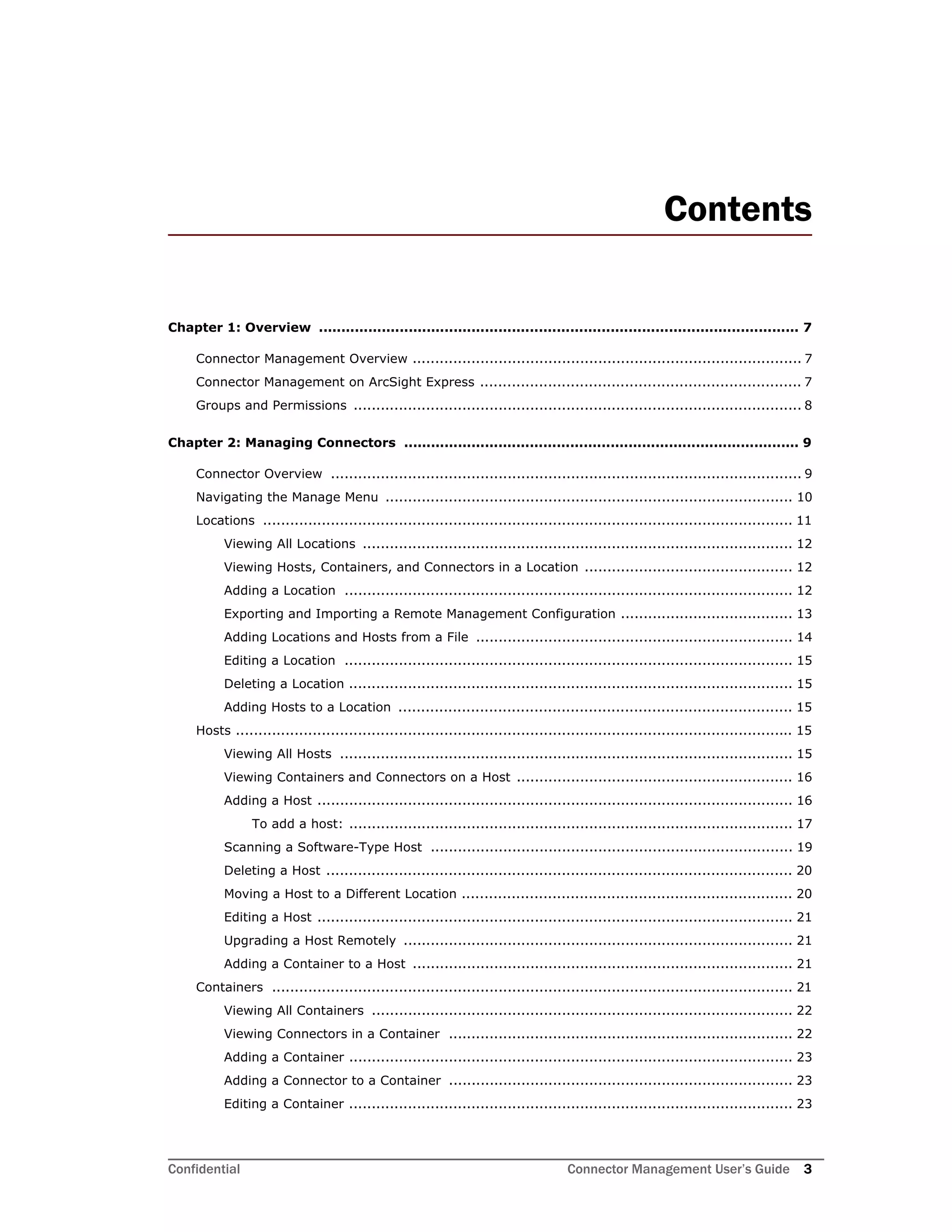
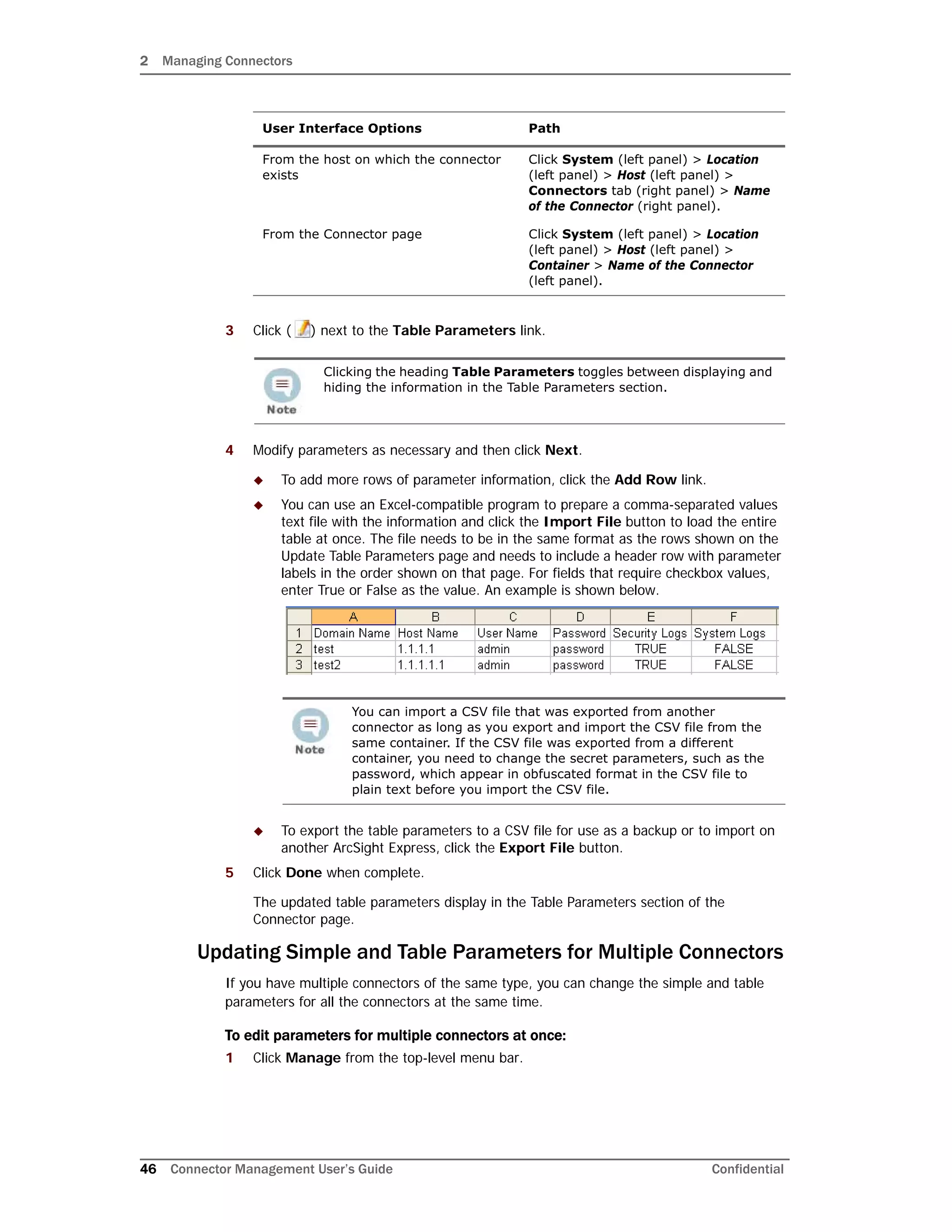
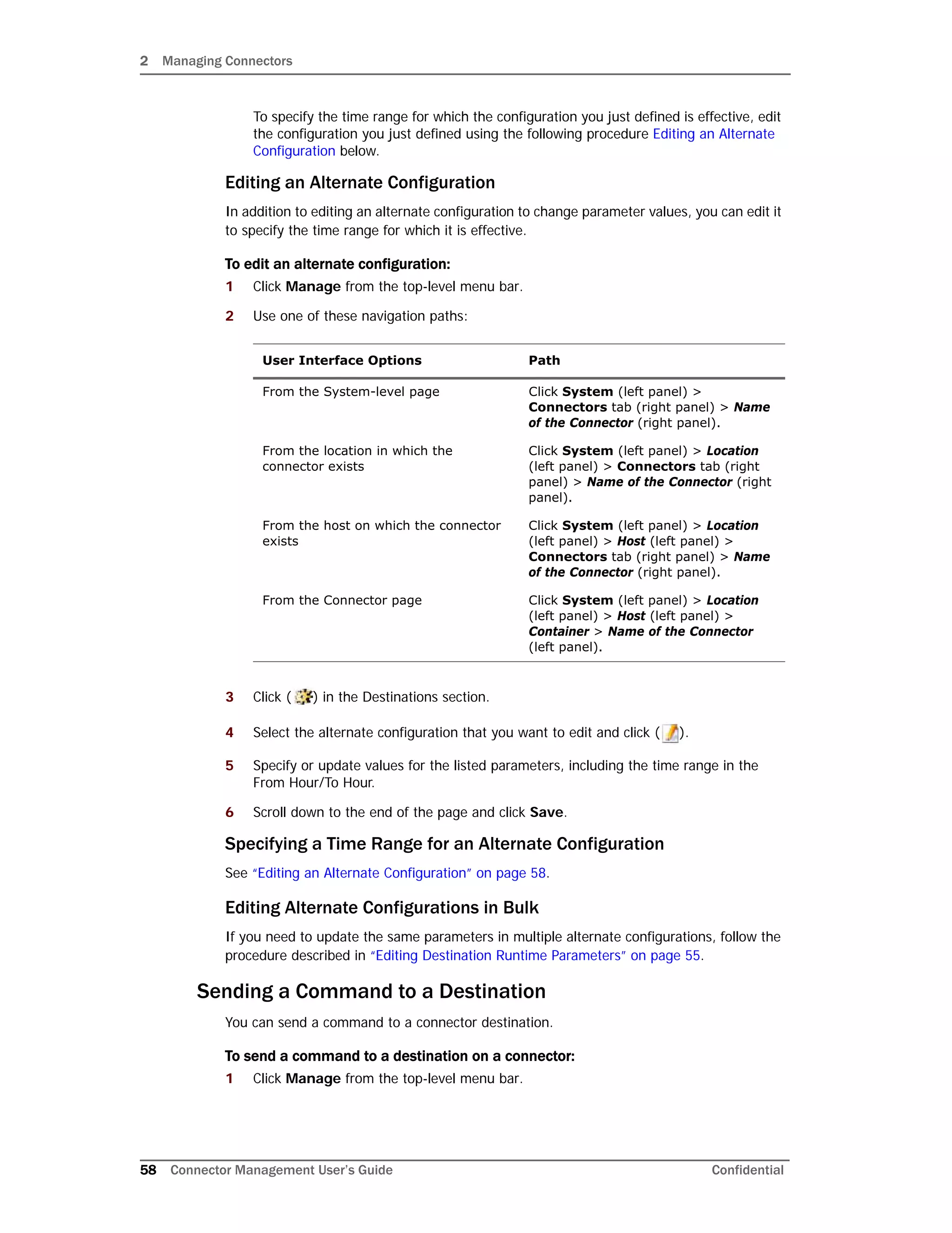
Applying a New Content AUP
You can add a new content AUP file to the repository and push it automatically to all
applicable connectors
To apply a new Content AUP:
1 Download the new Content AUP version from the support site at
http://support.openview.hp.com/ to the computer that you use to connect to the
browser-based interface.
2 From the computer to which you downloaded the AUP file, log in to the browser-based
interface.
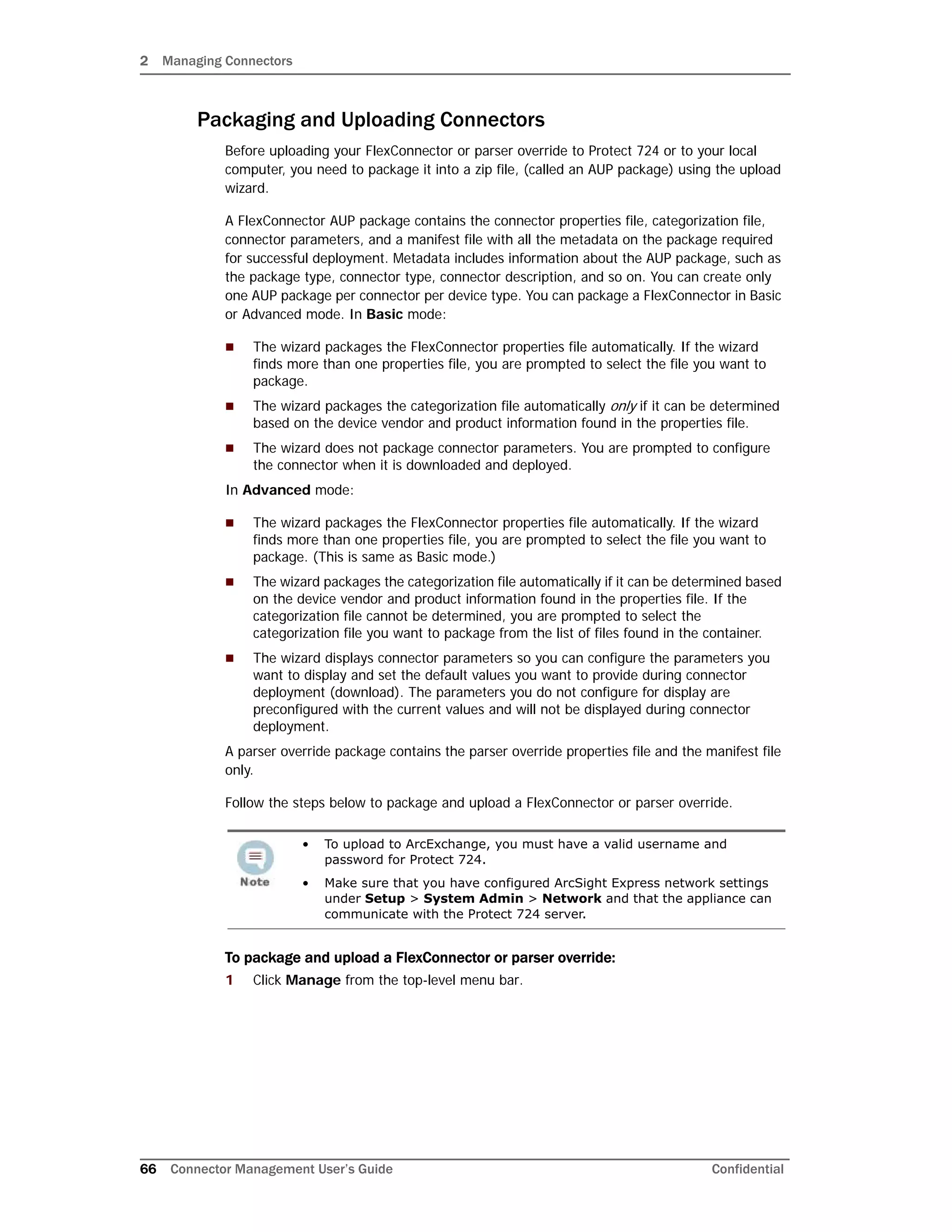
3 Click Repositories from the top-level menu bar.
4 Click Content AUP from the left panel.
5 Click Upload from the right panel.
6 Click Browse and select the file you downloaded earlier.
7 Click Submit to add the specified file to the repository and push it automatically to all
applicable connectors, or Cancel to quit.
You can verify the current Content AUP version on a connector by performing either of
these steps:
Run the GetStatus command on the connector destination and check that the value
for aup[acp].version is the same as the AUP version you applied. For information
about running a command on a connector destination, see “Sending a Command to a
Destination” on page 58.](https://image.slidesharecdn.com/connappadminguideae4-170530064024/75/Connector-Management-User-s-Guide-for-ArcSight-Express-v4-0-80-2048.jpg)
![3 Managing Repositories
84 Connector Management User’s Guide Confidential
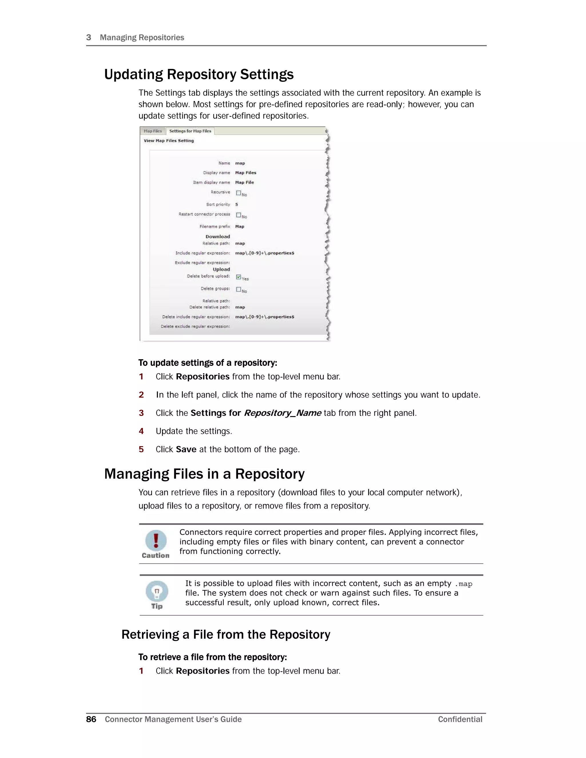
4 Click Save at the bottom of the page.
The new repository displays under the New Repository heading in the left-side
window panel.
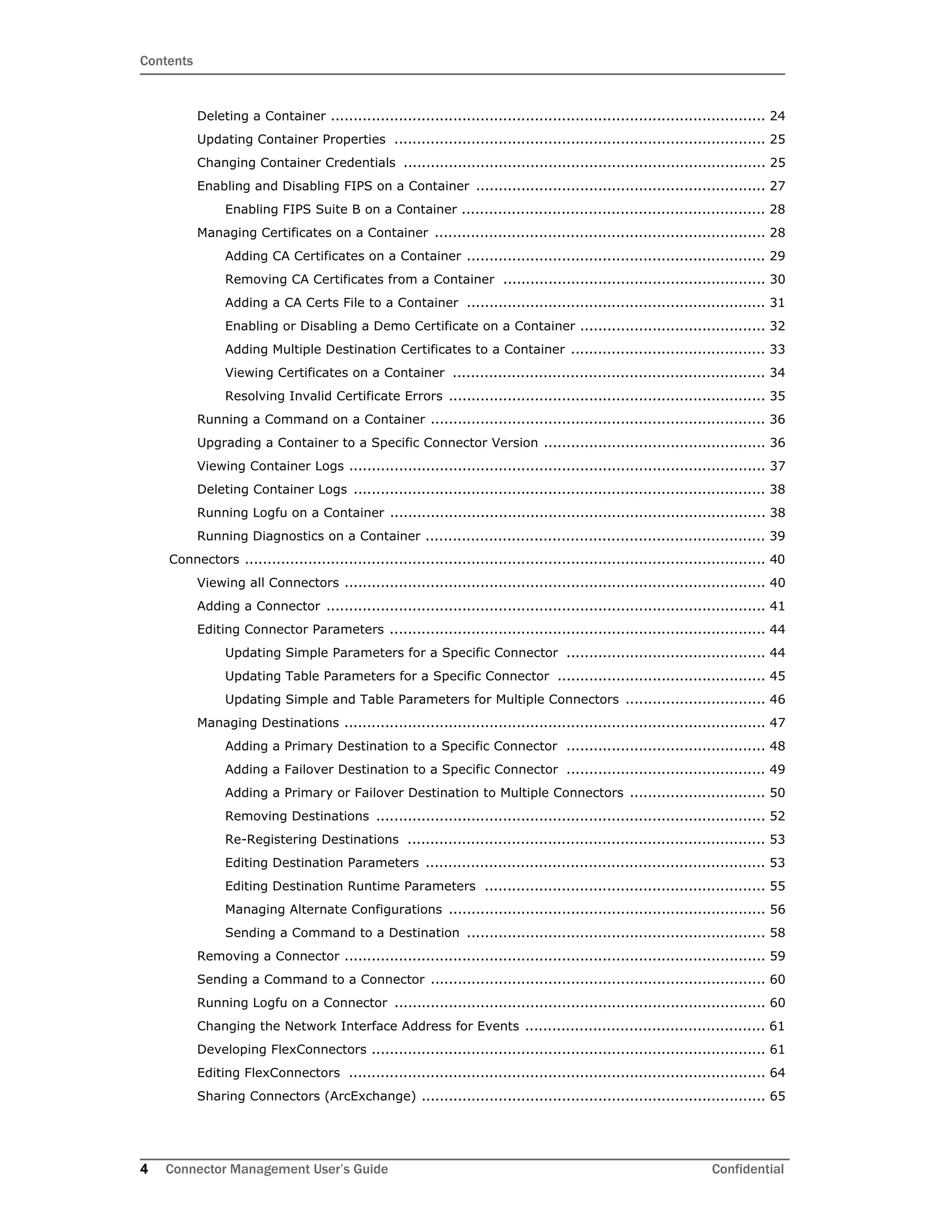
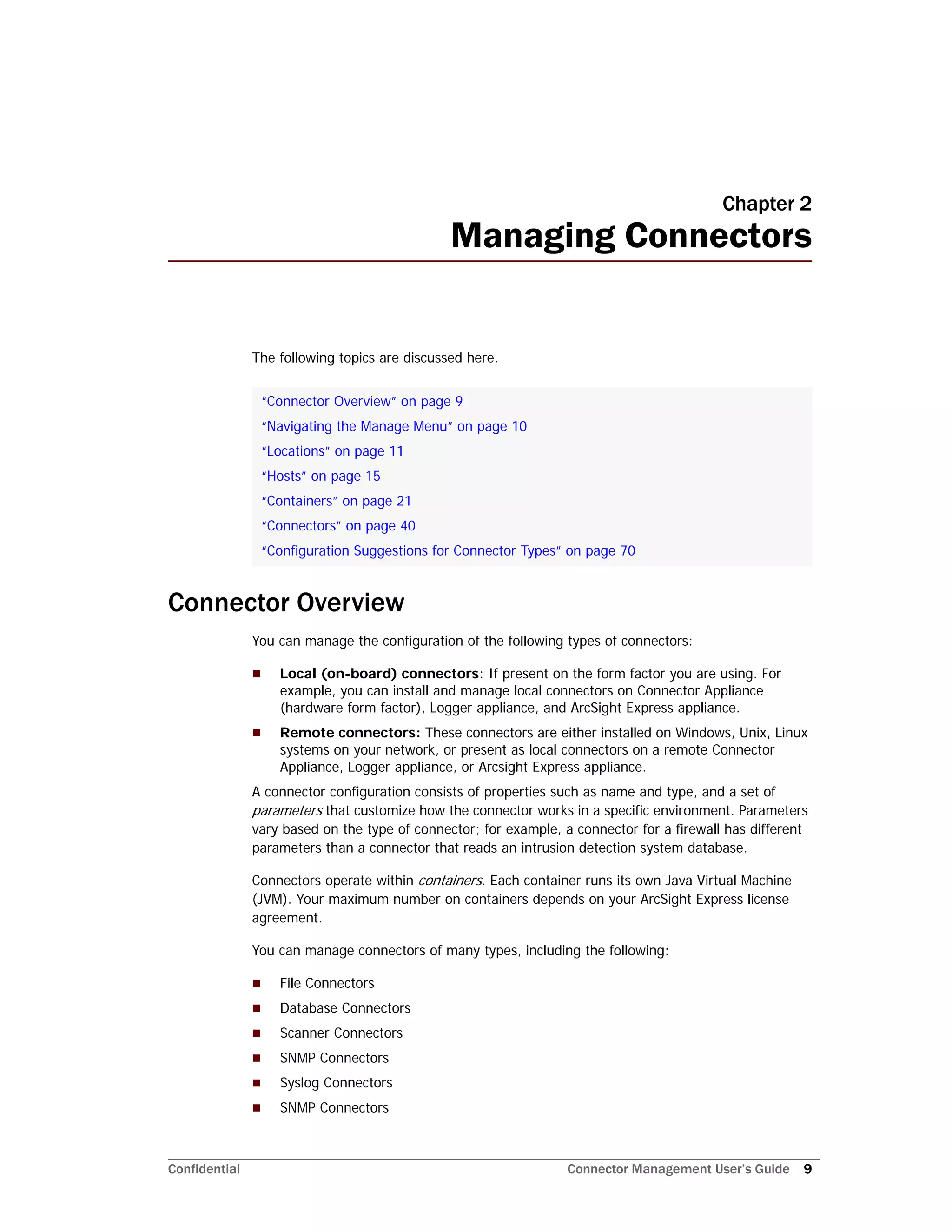
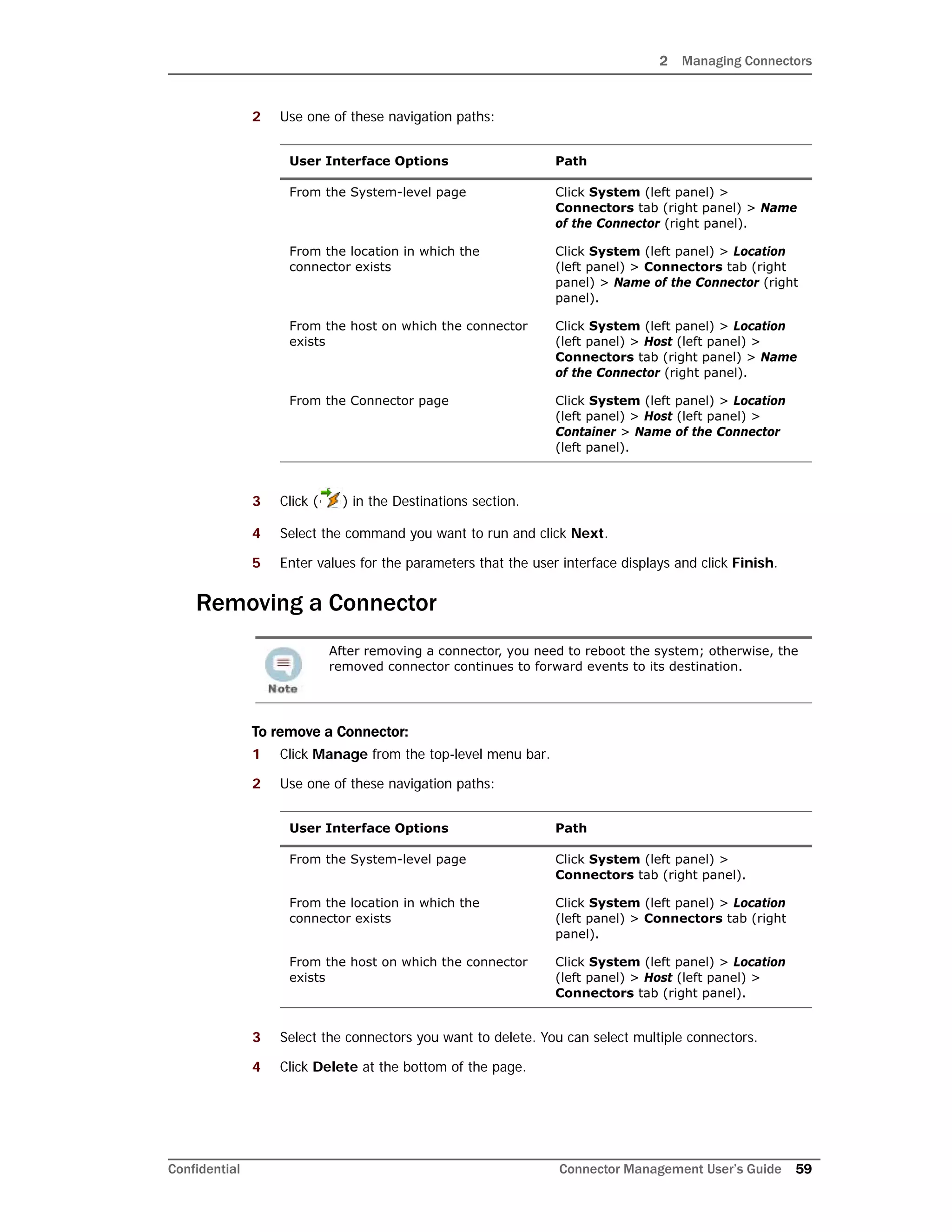
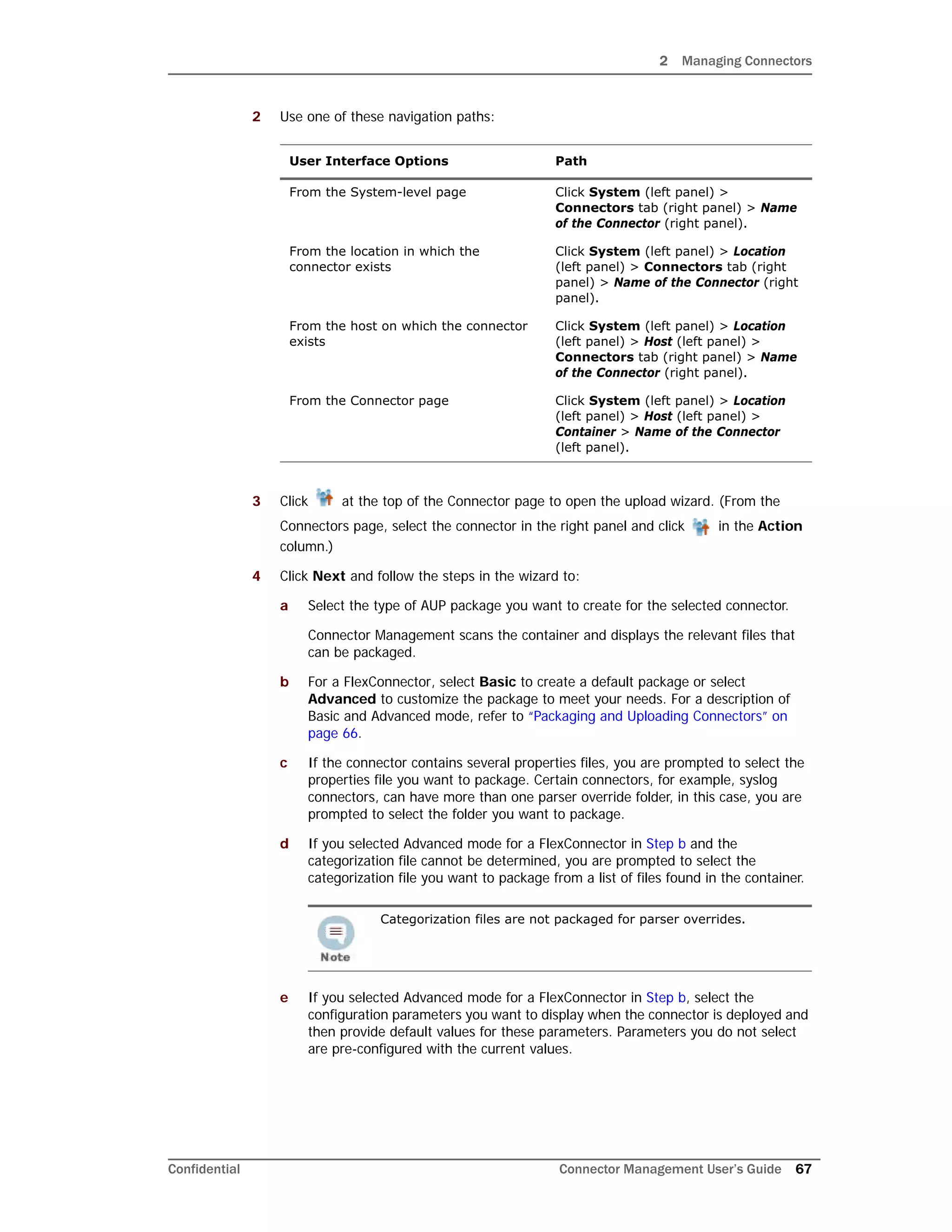
Retrieving Container Files
The Retrieve Container Files button copies a file from one or more connectors to a
repository. The specific files that are retrieved depend on the settings of a repository.
To retrieve a container file:
1 Click Repositories from the top-level menu bar.
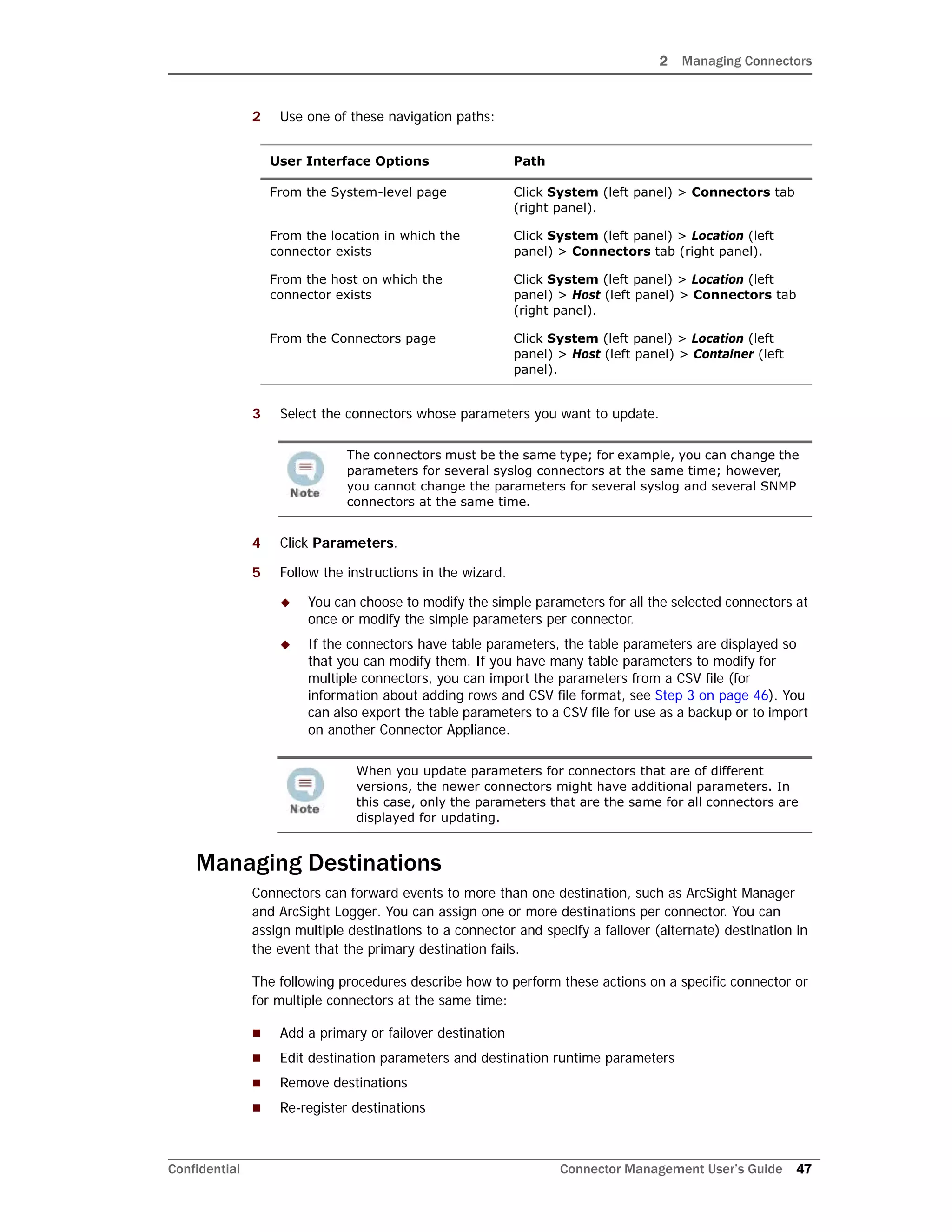
Sort Priority -1 by default
Restart Connector
Process
Check to restart the connector process after file operations.
Filename Prefix An identifying word that is included in the names of
retrieved files. For example, map files are identified by Map
in the file name:
localhost_Container_-1.Map-2009-04-06_12-22-25-607
.zip
Relative path
(Download)
The path for download, relative to $ARCSIGHT_HOME, for
example, user/agent/map or user/agent/flexagent.
Leave this field blank to specify files in $ARCSIGHT_HOME.
Note: The relative path is used for download only.
Include Regular
Expression
A description of filenames to include. Use .* to specify all
files. The following example selects properties files that
consist of map. followed by one or more digits, followed by
.properties:
map.[0-9]+.properties$
Exclude Regular
Expression
A description of filenames to exclude. The following
example excludes all files with a certain prefix or in the
agentdata folder.
(agentdata/|cwsapi_fileset_).*$
Delete Before Upload Check to delete earlier copies before upload.
CAUTION: If you check Delete Before Upload and do not
specify a Relative path (Upload), all files and folders in
current/user/agent will be deleted.
Delete Groups Whether to delete folders recursively in
$ARCSIGHT_HOME/user/agent/map directory.
Relative path (Upload) The path for upload, relative to
$ARCSIGHT_HOME/current/user/agent/flexagent/
<connectorname>
Delete Relative Path Whether the directory specified in Relative Path (Upload)
and its contents should be removed when a file is uploaded
from the repository.
Delete Include Regular
Expression
Typically the same as the Include Regular Expression.
Delete Exclude Regular
Expression
Typically the same as the Exclude Regular Expression.
Parameter Description](https://image.slidesharecdn.com/connappadminguideae4-170530064024/75/Connector-Management-User-s-Guide-for-ArcSight-Express-v4-0-84-2048.jpg)
![3 Managing Repositories
88 Connector Management User’s Guide Confidential
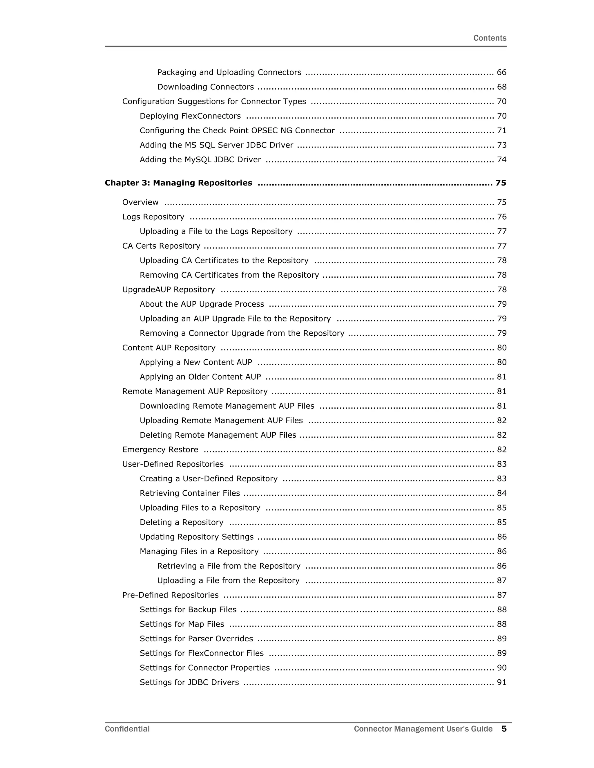
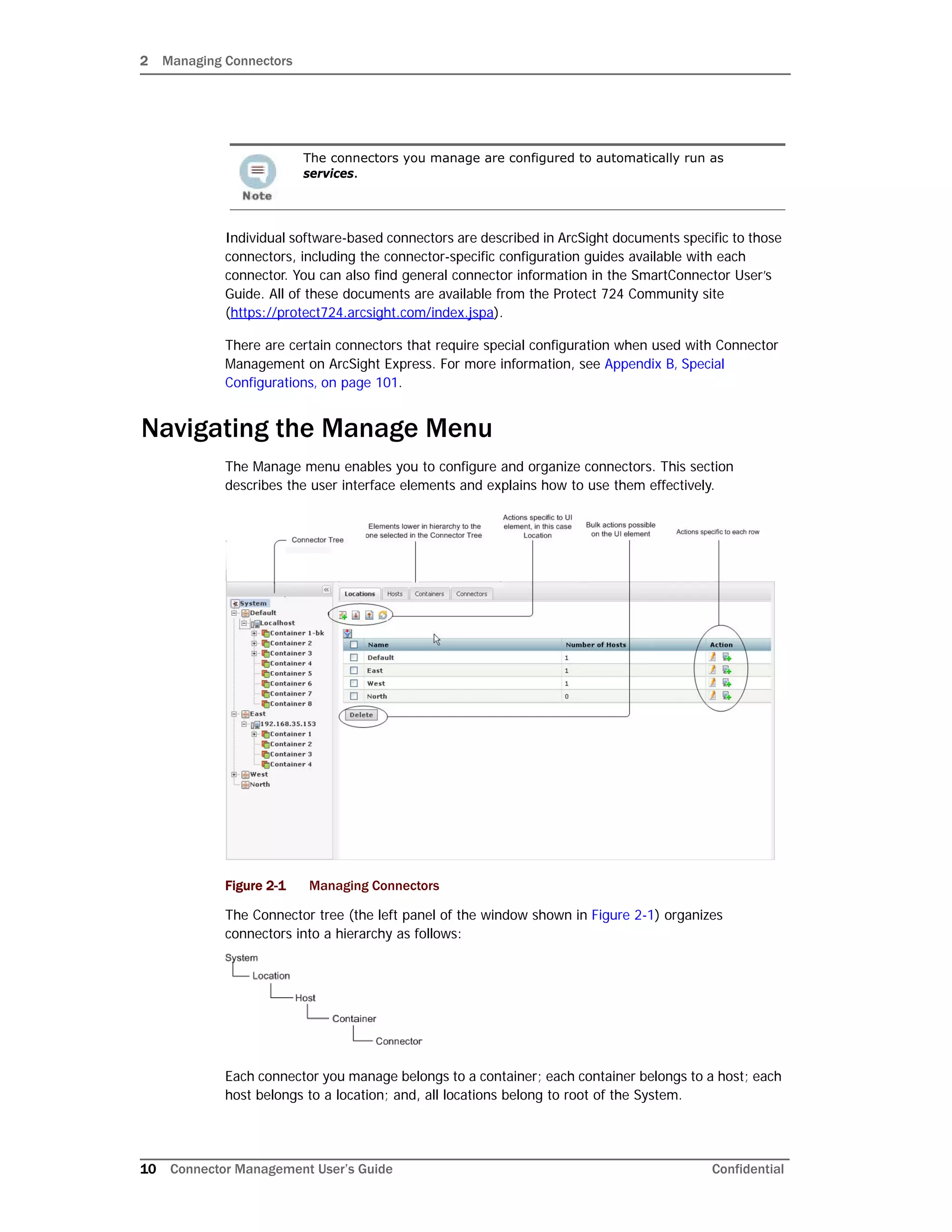
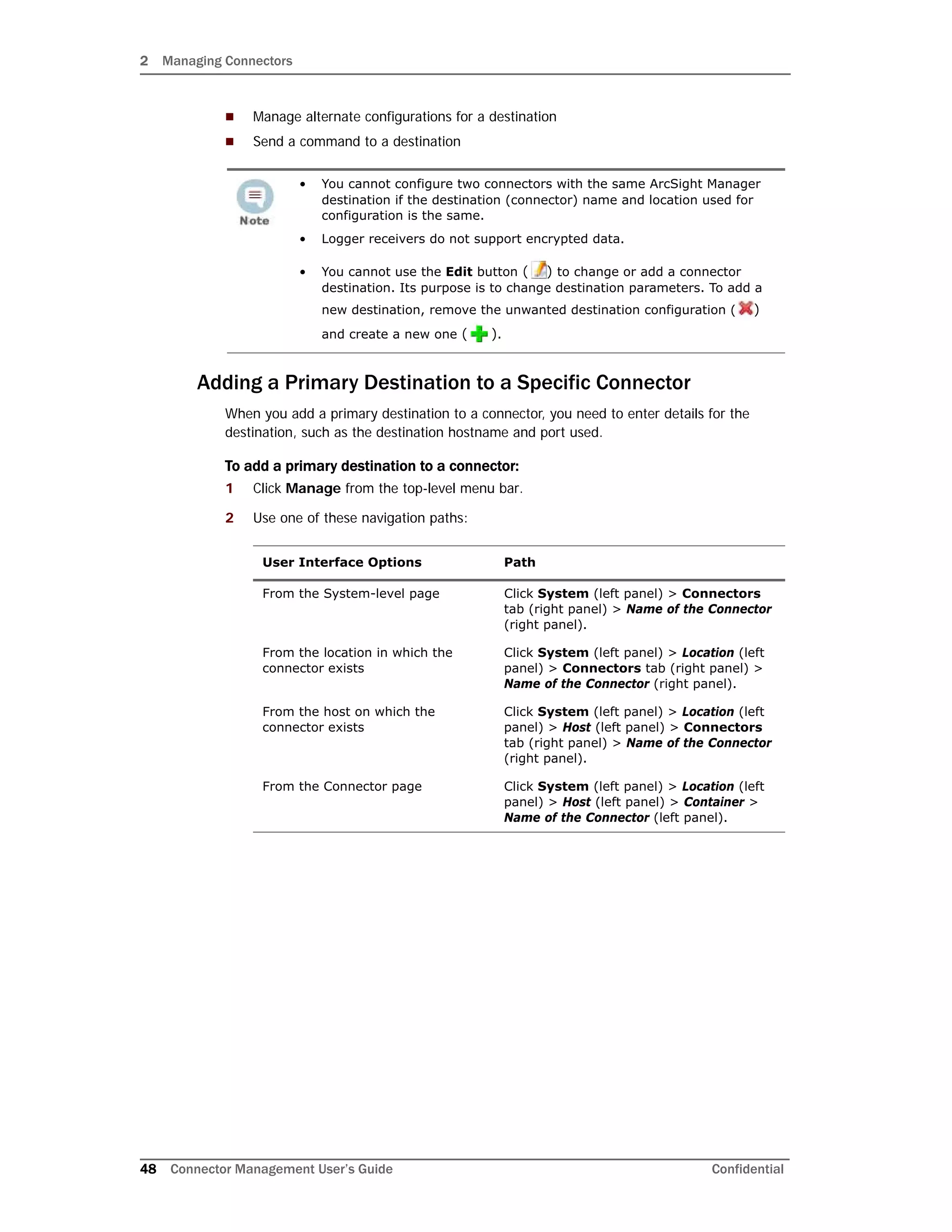
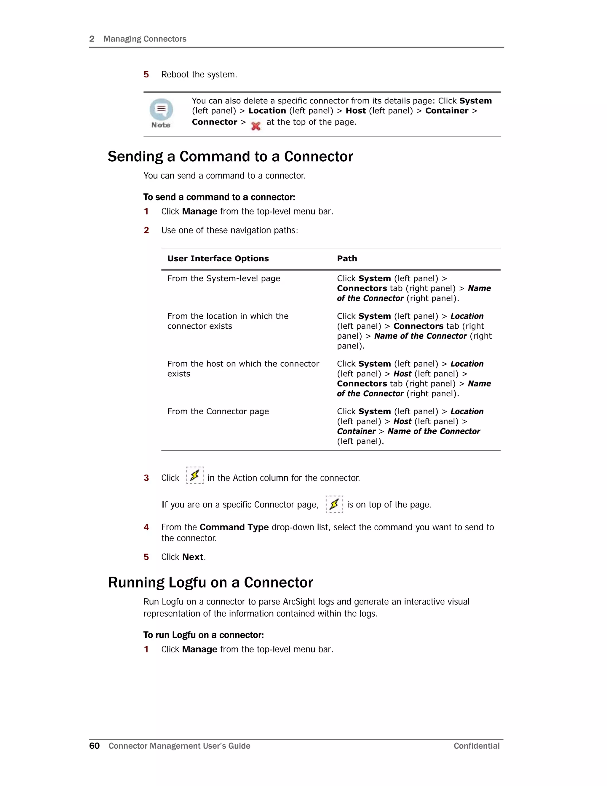
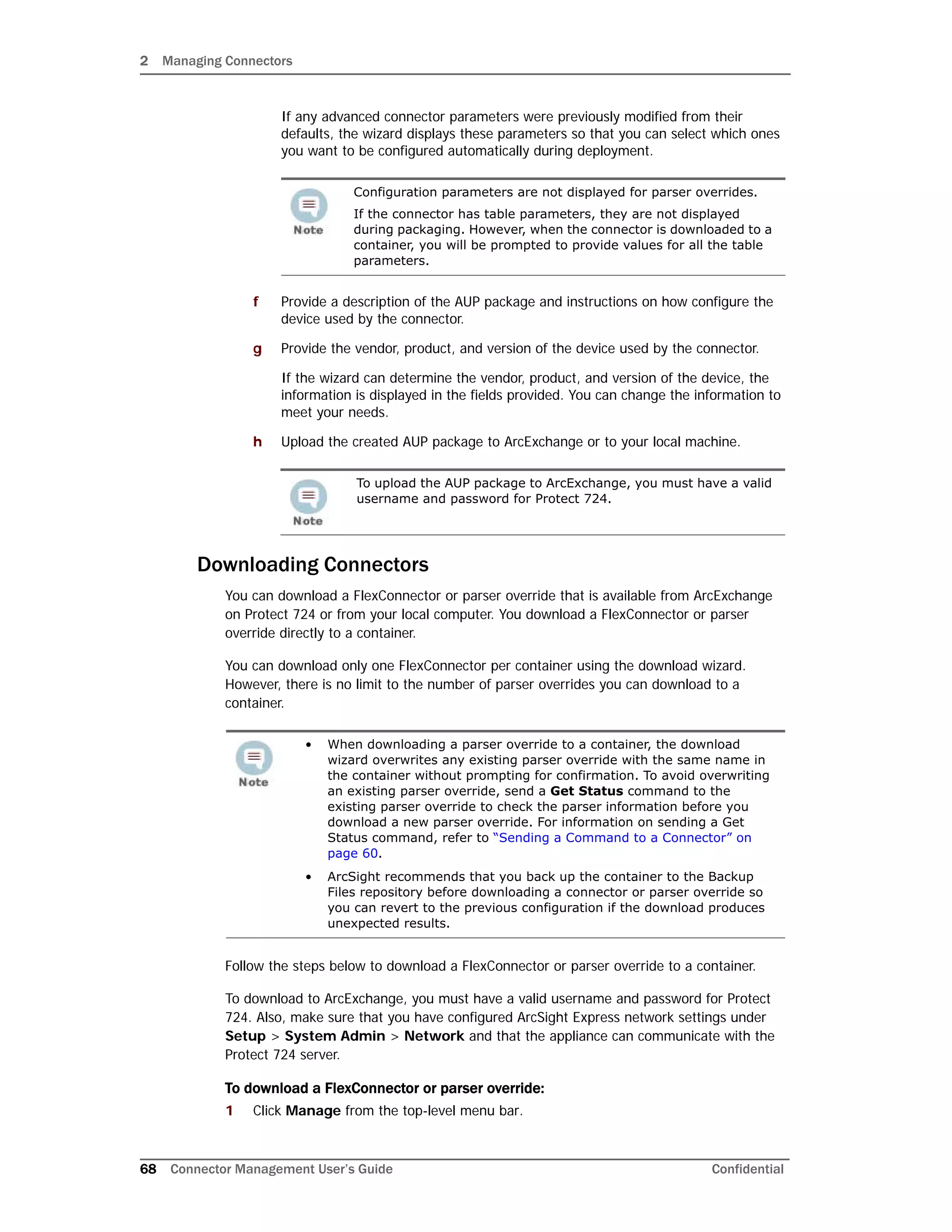
Settings for Backup Files
This table lists pre-defined settings for backup files.
Settings for Map Files
This table lists pre-defined settings for map files.
Name Default Setting
Name backup
Display Name Backup Files
Item Display Name Backup File
Recursive Checked (Yes)
Sort Priority 0
Restart Connector Process Checked (Yes)
Filename Prefix ConnectorBackup
Download Relative Path
Download Include regular expression
Download Exclude regular expression (agentdata/|cwsapi_fileset_).*$
Delete before upload Checked (Yes)
Delete groups Checked (Yes)
Upload Relative Path
Delete Relative Path
Delete Include regular expression
Delete Exclude regular expression (agentdata/|cwsapi_fileset_).*$
Name Default Setting
Name map
Display Name Map Files
Item Display Name Map File
Recursive Un-checked (No)
Sort Priority 5
Restart Connector Process Un-checked (No)
Filename Prefix Map
Download Relative Path map
Download Include regular expression map.[0-9]+.properties$
Download Exclude regular expression
Delete before upload Checked (Yes)](https://image.slidesharecdn.com/connappadminguideae4-170530064024/75/Connector-Management-User-s-Guide-for-ArcSight-Express-v4-0-88-2048.jpg)
![3 Managing Repositories
Confidential Connector Management User’s Guide 89
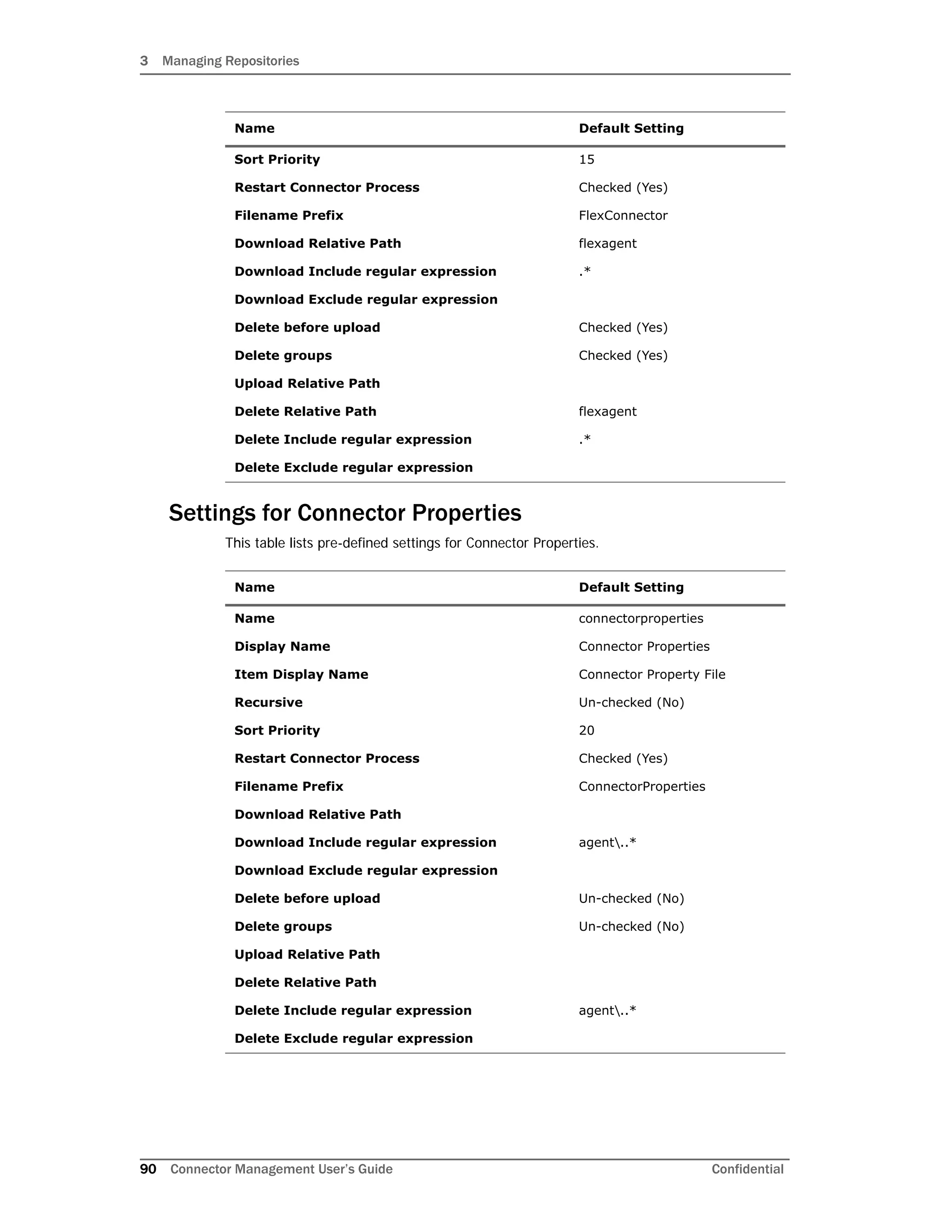
Settings for Parser Overrides
This table lists pre-defined settings for parser overrides.
Settings for FlexConnector Files
This table lists pre-defined settings for FlexConnector files.
Delete groups Un-checked (No)
Upload Relative Path
Delete Relative Path map
Delete Include regular expression map.[0-9]+.properties$
Delete Exclude regular expression
Name Default Setting
Name parseroverrides
Display Name Parser Overrides
Item Display Name Parser Override
Recursive Checked (Yes)
Sort Priority 10
Restart Connector Process Checked (Yes)
Filename Prefix Parsers
Download Relative Path fcp
Download Include regular expression .*
Download Exclude regular expression
Delete before upload Checked (Yes)
Delete groups Checked (Yes)
Upload Relative Path
Delete Relative Path fcp
Delete Include regular expression .*
Delete Exclude regular expression
Name Default Setting
Name flexconnectors
Display Name Flex Connector Files
Item Display Name Flex Connector File
Recursive Checked (Yes)
Name Default Setting](https://image.slidesharecdn.com/connappadminguideae4-170530064024/75/Connector-Management-User-s-Guide-for-ArcSight-Express-v4-0-89-2048.jpg)


![B Special Configurations
Confidential Connector Management User’s Guide 103
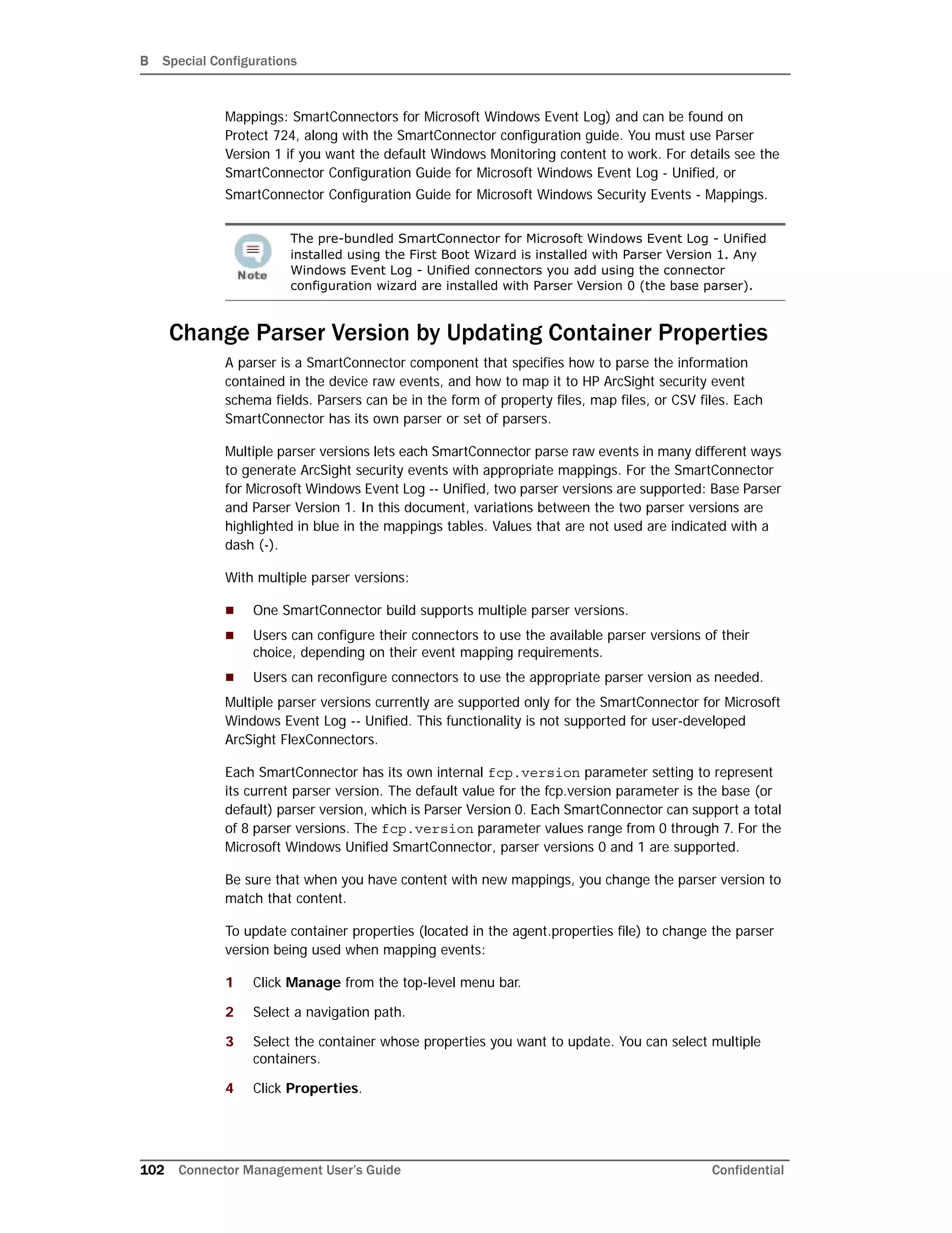
5 Follow the instructions in the wizard to update connector properties.
The fcp.version parameter value 0 designates the base parser. To use parser 1,
change the fcp.version parameter value to 1. For example:
agents[0].fcp.version=1
SSL Authentication
If you choose to use SSL as the connection protocol, you will be required to add security
certificates for both the Windows Domain Controller Service and for the Active Directory
Server. Installing a valid certificate on a domain controller permits the LDAP service to
listen for, and automatically accept, SSL connections for both LDAP and global catalog
traffic. With the First Boot Wizard installation of the connector, the certificates are already
imported for you. If you add Windows Event Log - Unified connectors, see the
SmartConnector Configuration Guide for Microsoft Windows Event Log - Unified for
instructions.
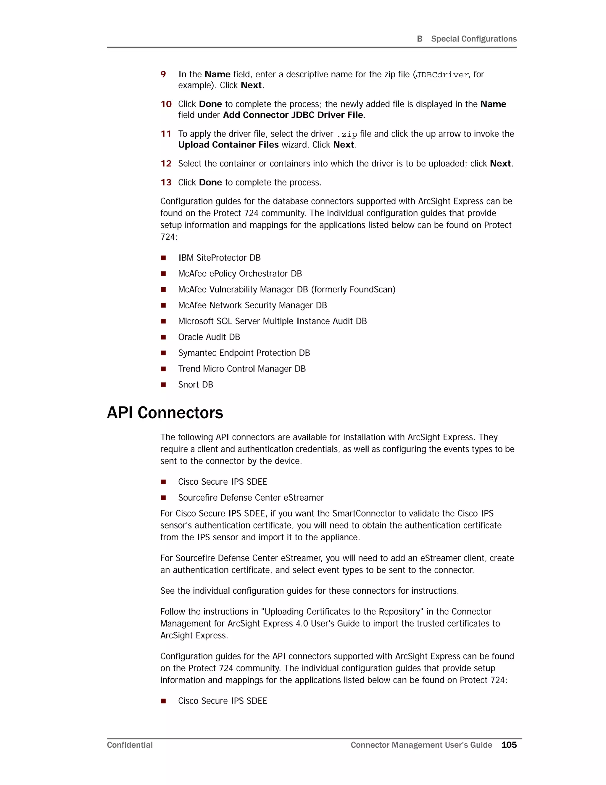
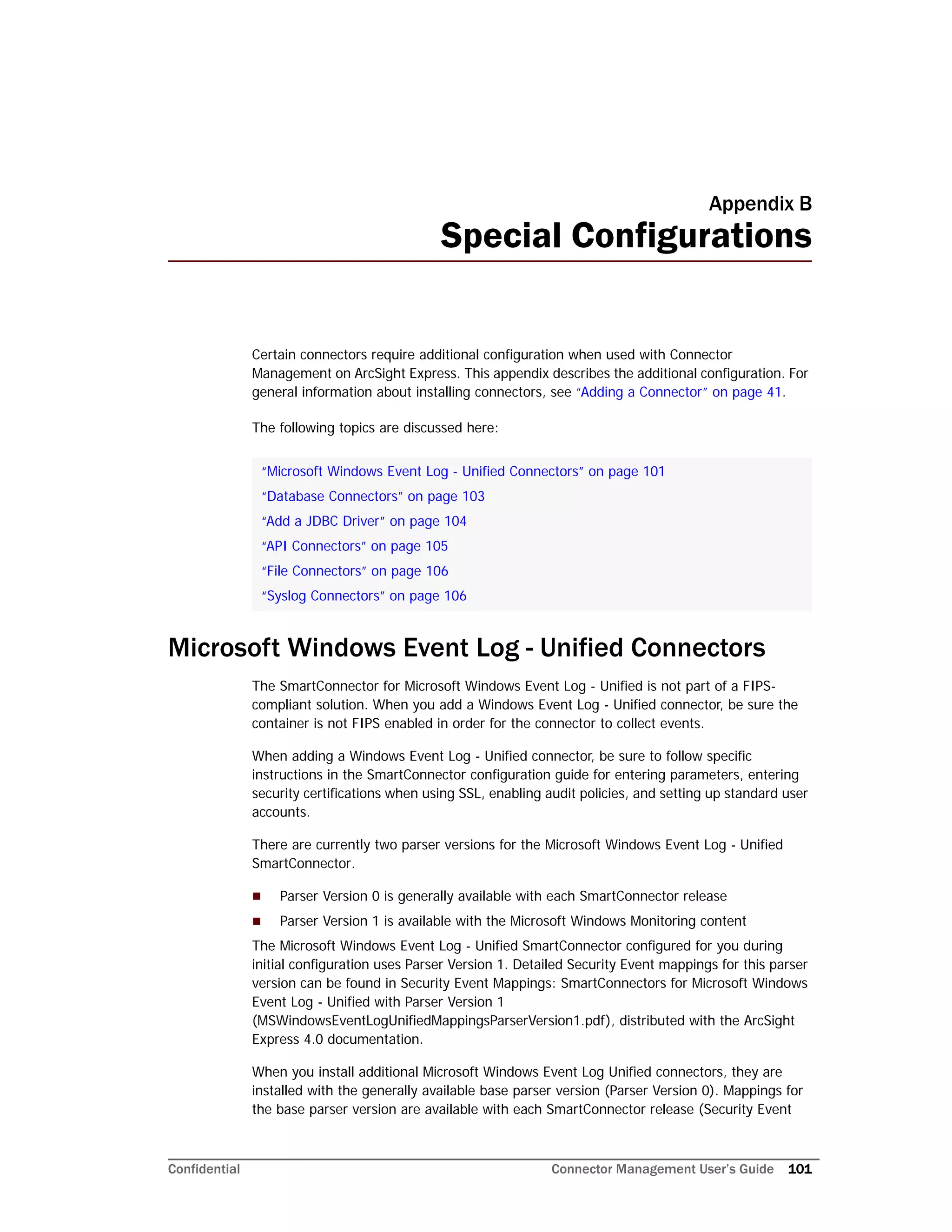
Database Connectors
The following database connectors are available for installation with ArcSight Express:
IBM SiteProtector DB*
McAfee ePolicy Orchestrator DB*
McAfee Vulnerability Manager DB*
McAfee Network Security Manager DB*
Microsoft SQL Server Audit Multiple Instance DB*
Oracle Audit DB
Symantec Endpoint Protection DB*
Trend Micro Control Manager NG DB*
Snort DB*
*These connectors extract events from an SQL Server or MySQL databases, which requires
a JDBC driver. See “Add a JDBC Driver” on page 104 for instructions.
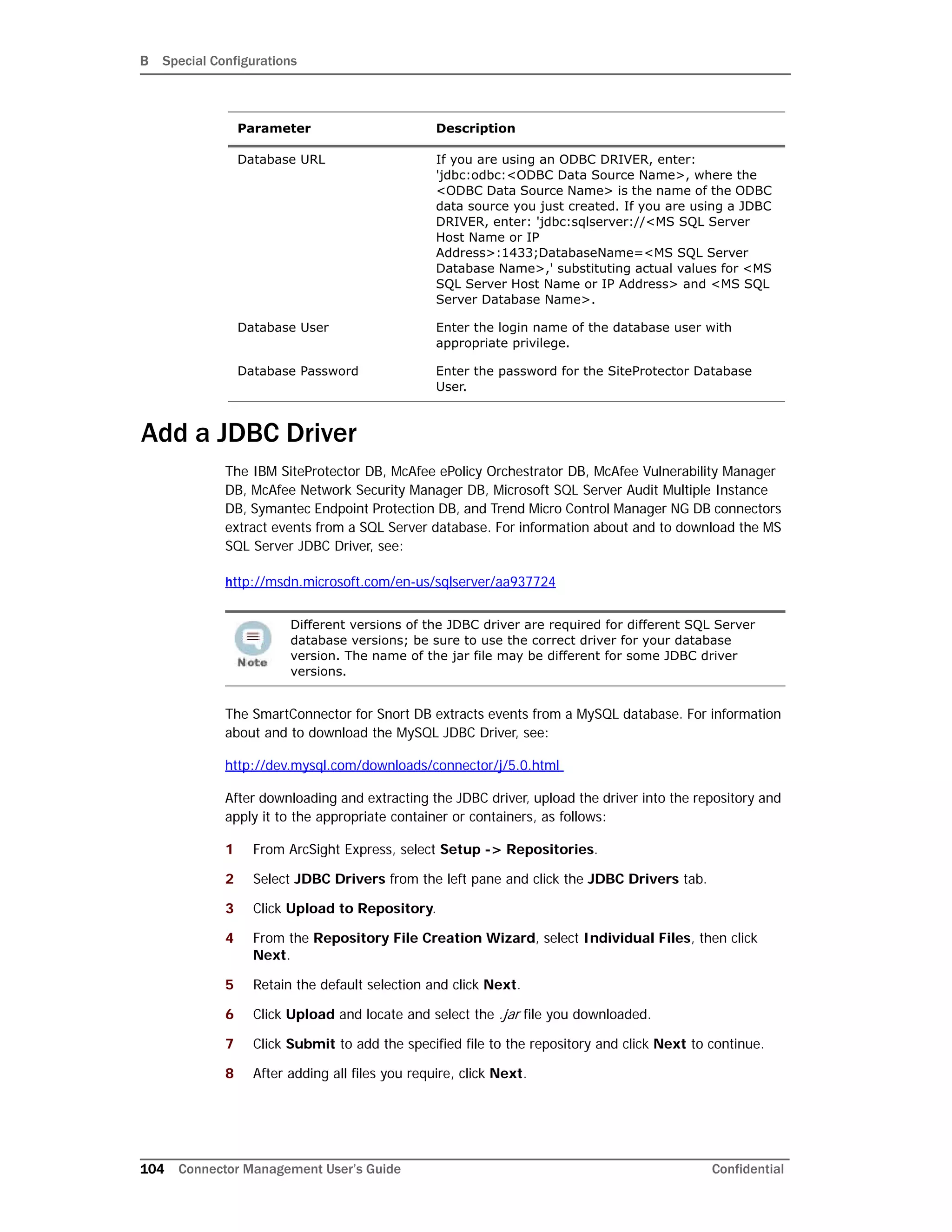
At the least, all of these database connectors require the following information when being
added to ArcSight Express; some connectors require additional parameters, such as event
types or polling frequency.
Parameter Description
Database JDBC Driver If you are using an ODBC DRIVER, select
'sun.jdbc.odbc.JdbcOdbcDriver' driver. For JDBC
drivers, select the
'com.microsoft.sqlserver.jdbc.SQLServerDriver' driver.
If you are using an ODBC DRIVER, select
'sun.jdbc.odbc.JdbcOdbcDriver' driver. For JDBC
drivers, select the
'com.microsoft.sqlserver.jdbc.SQLServerDriver' driver.](https://image.slidesharecdn.com/connappadminguideae4-170530064024/75/Connector-Management-User-s-Guide-for-ArcSight-Express-v4-0-103-2048.jpg)