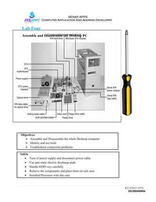
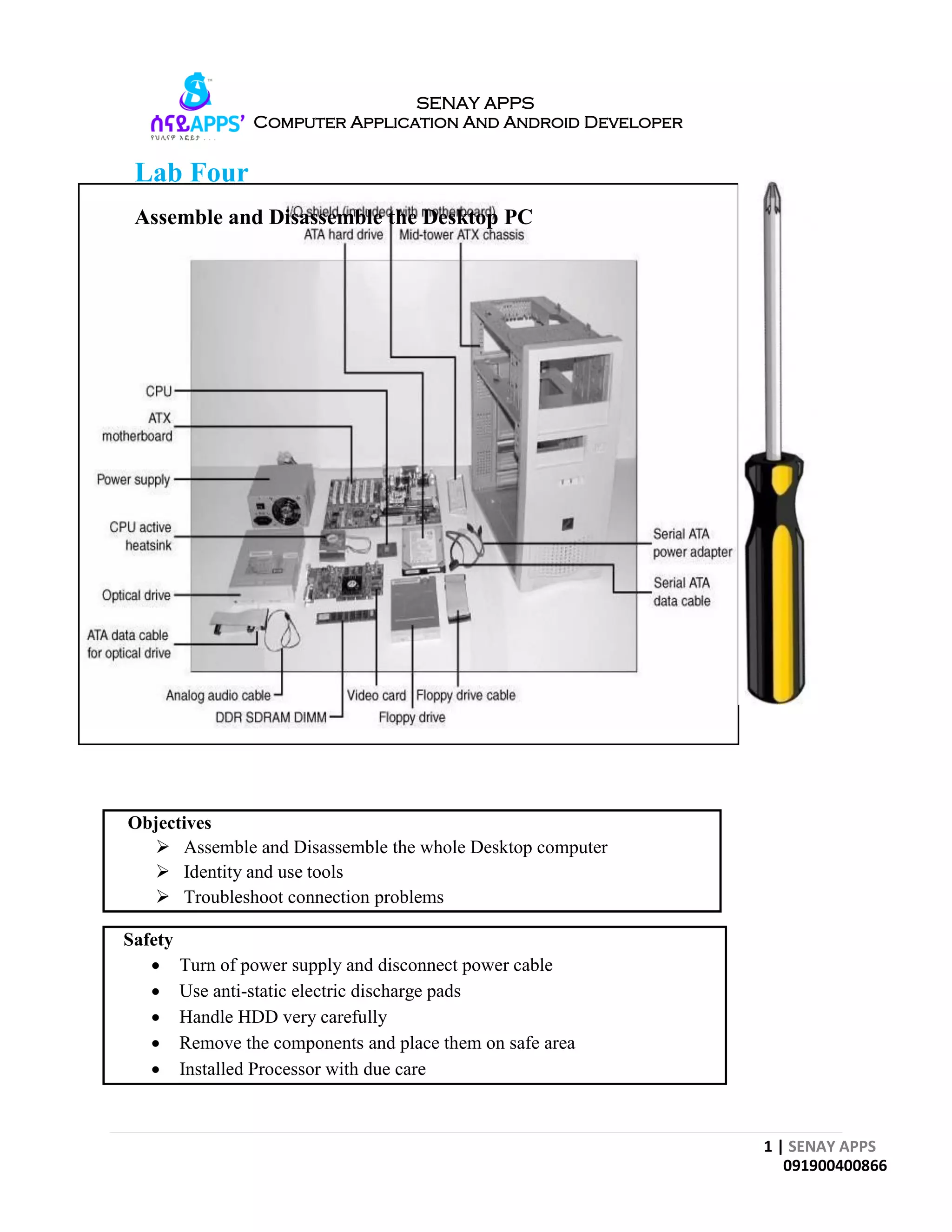
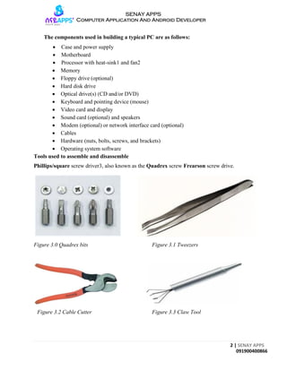
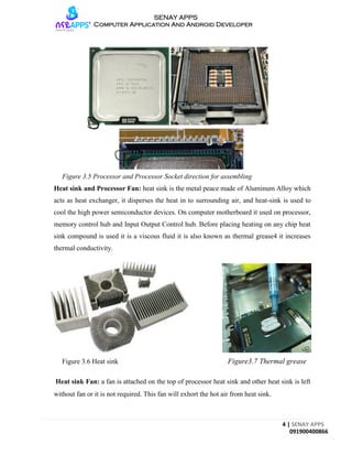
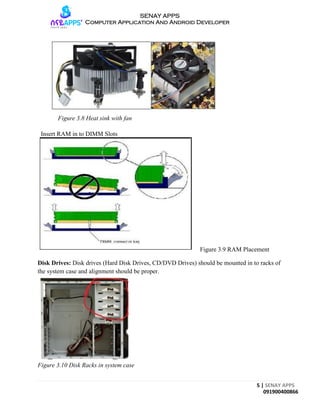
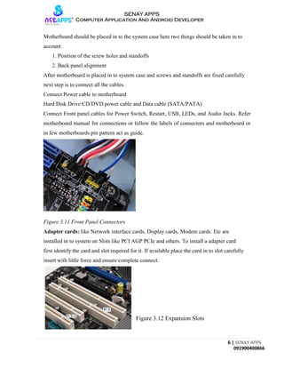
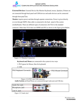
1 | SENAY APPS
091900400866
SENAY APPS
Computer Application And Android Developer
Lab Four
Assemble and Disassemble the Desktop PC
Objectives
 Assemble and Disassemble the whole Desktop computer
 Identity and use tools
 Troubleshoot connection problems
Safety
 Turn of power supply and disconnect power cable
 Use anti-static electric discharge pads
 Handle HDD very carefully
 Remove the components and place them on safe area
 Installed Processor with due care
2 | SENAY APPS
091900400866
SENAY APPS
Computer Application And Android Developer
The components used in building a typical PC are as follows:
 Case and power supply
 Motherboard
 Processor with heat-sink1 and fan2
 Memory
 Floppy drive (optional)
 Hard disk drive
 Optical drive(s) (CD and/or DVD)
 Keyboard and pointing device (mouse)
 Video card and display
 Sound card (optional) and speakers
 Modem (optional) or network interface card (optional)
 Cables
 Hardware (nuts, bolts, screws, and brackets)
 Operating system software
Tools used to assemble and disassemble
Phillips/square screw driver3, also known as the Quadrex screw Frearson screw drive.
Figure 3.0 Quadrex bits Figure 3.1 Tweezers
Figure 3.2 Cable Cutter Figure 3.3 Claw Tool
3 | SENAY APPS
091900400866
SENAY APPS
Computer Application And Android Developer
The following sections cover the assembly and disassembly procedure:
1. System Case and Power Supply
2. Motherboard, Processor, Heat sink, RAM.
3. Adapter cards
4. Disk Drives
5. External Devices
System Case and Power supply (SMPS)
System Case and Power Supply are available as single unit pre-attached, if not, assemble the
power supply as fallows.
Figure 3.3 SMPS Figure 3.4 System Case
Note: SMPS should be set to proper Input Voltage Level 220 or 110.
Motherboard
Motherboard should be prepared as follows
Processor: While inserting Processor, in to processor socket. One should follow the marking
on the processor and processor socket they should be on same side.
4 | SENAY APPS
091900400866
SENAY APPS
Computer Application And Android Developer
Figure 3.5 Processor and Processor Socket direction for assembling
Heat sink and Processor Fan: heat sink is the metal peace made of Aluminum Alloy which
acts as heat exchanger, it disperses the heat in to surrounding air, and heat-sink is used to
cool the high power semiconductor devices. On computer motherboard it used on processor,
memory control hub and Input Output Control hub. Before placing heating on any chip heat
sink compound is used it is a viscous fluid it is also known as thermal grease4 it increases
thermal conductivity.
Figure 3.6 Heat sink Figure3.7 Thermal grease
Heat sink Fan: a fan is attached on the top of processor heat sink and other heat sink is left
without fan or it is not required. This fan will exhort the hot air from heat sink.
5 | SENAY APPS
091900400866
SENAY APPS
Computer Application And Android Developer
Figure 3.8 Heat sink with fan
Insert RAM in to DIMM Slots
Figure 3.9 RAM Placement
Disk Drives: Disk drives (Hard Disk Drives, CD/DVD Drives) should be mounted in to racks of
the system case and alignment should be proper.
Figure 3.10 Disk Racks in system case
6 | SENAY APPS
091900400866
SENAY APPS
Computer Application And Android Developer
Motherboard should be placed in to the system case here two things should be taken in to
account.
1. Position of the screw holes and standoffs
2. Back panel alignment
After motherboard is placed in to system case and screws and standoffs are fixed carefully
next step is to connect all the cables.
Connect Power cable to motherboard
Hard Disk Drive CD/DVD power cable and Data cable (SATA/PATA)
Connect Front panel cables for Power Switch, Restart, USB, LEDs, and Audio Jacks. Refer
motherboard manual for connections or follow the labels of connectors and motherboard or
in few motherboards pin pattern act as guide.
Figure 3.11 Front Panel Connectors
Adapter cards: like Network interface cards, Display cards, Modem cards. Etc are
installed in to system on Slots like PCI AGP PCIe and others. To install a adapter card
first identify the card and slot required for it. If available place the card in to slot carefully
insert with little force and ensure complete connect.
Figure 3.12 Expansion Slots
7 | SENAY APPS
091900400866
SENAY APPS
Computer Application And Android Developer
External Devices: External Device like Monitor Keyboard, mouse, Speakers, Printers etc
are connected through back panel and USB devices and audio devices can be connected
5
through front panel also
Monitor requires power and data through separate connections. Power is given directly
or even through SMPS, Data cable is connected to the back –panel of the system
(motherboard). There are different types of connectors, but VGA is the standard
connector. Other than VGA there are HDMI and DVI as shown in the figure given below.
Figure 3.13 Monitor Connectors
Keyboard and Mouse are connected to the system in two ways
1. PS/2 (green for Mouse, blue for keyboard)
2. USB
Figure 3.14 PS/2 and USB connector
Audio System and Head Phones are connected through Audio jack and USB also.
Figure 3.15 Audio Jack

Computer Hardware & Software Lab Manual 4

  • 1.
    1 | SENAYAPPS 091900400866 SENAY APPS Computer Application And Android Developer Lab Four Assemble and Disassemble the Desktop PC Objectives  Assemble and Disassemble the whole Desktop computer  Identity and use tools  Troubleshoot connection problems Safety  Turn of power supply and disconnect power cable  Use anti-static electric discharge pads  Handle HDD very carefully  Remove the components and place them on safe area  Installed Processor with due care
  • 2.
    2 | SENAYAPPS 091900400866 SENAY APPS Computer Application And Android Developer The components used in building a typical PC are as follows:  Case and power supply  Motherboard  Processor with heat-sink1 and fan2  Memory  Floppy drive (optional)  Hard disk drive  Optical drive(s) (CD and/or DVD)  Keyboard and pointing device (mouse)  Video card and display  Sound card (optional) and speakers  Modem (optional) or network interface card (optional)  Cables  Hardware (nuts, bolts, screws, and brackets)  Operating system software Tools used to assemble and disassemble Phillips/square screw driver3, also known as the Quadrex screw Frearson screw drive. Figure 3.0 Quadrex bits Figure 3.1 Tweezers Figure 3.2 Cable Cutter Figure 3.3 Claw Tool
  • 3.
    3 | SENAYAPPS 091900400866 SENAY APPS Computer Application And Android Developer The following sections cover the assembly and disassembly procedure: 1. System Case and Power Supply 2. Motherboard, Processor, Heat sink, RAM. 3. Adapter cards 4. Disk Drives 5. External Devices System Case and Power supply (SMPS) System Case and Power Supply are available as single unit pre-attached, if not, assemble the power supply as fallows. Figure 3.3 SMPS Figure 3.4 System Case Note: SMPS should be set to proper Input Voltage Level 220 or 110. Motherboard Motherboard should be prepared as follows Processor: While inserting Processor, in to processor socket. One should follow the marking on the processor and processor socket they should be on same side.
  • 4.
    4 | SENAYAPPS 091900400866 SENAY APPS Computer Application And Android Developer Figure 3.5 Processor and Processor Socket direction for assembling Heat sink and Processor Fan: heat sink is the metal peace made of Aluminum Alloy which acts as heat exchanger, it disperses the heat in to surrounding air, and heat-sink is used to cool the high power semiconductor devices. On computer motherboard it used on processor, memory control hub and Input Output Control hub. Before placing heating on any chip heat sink compound is used it is a viscous fluid it is also known as thermal grease4 it increases thermal conductivity. Figure 3.6 Heat sink Figure3.7 Thermal grease Heat sink Fan: a fan is attached on the top of processor heat sink and other heat sink is left without fan or it is not required. This fan will exhort the hot air from heat sink.
  • 5.
    5 | SENAYAPPS 091900400866 SENAY APPS Computer Application And Android Developer Figure 3.8 Heat sink with fan Insert RAM in to DIMM Slots Figure 3.9 RAM Placement Disk Drives: Disk drives (Hard Disk Drives, CD/DVD Drives) should be mounted in to racks of the system case and alignment should be proper. Figure 3.10 Disk Racks in system case
  • 6.
    6 | SENAYAPPS 091900400866 SENAY APPS Computer Application And Android Developer Motherboard should be placed in to the system case here two things should be taken in to account. 1. Position of the screw holes and standoffs 2. Back panel alignment After motherboard is placed in to system case and screws and standoffs are fixed carefully next step is to connect all the cables. Connect Power cable to motherboard Hard Disk Drive CD/DVD power cable and Data cable (SATA/PATA) Connect Front panel cables for Power Switch, Restart, USB, LEDs, and Audio Jacks. Refer motherboard manual for connections or follow the labels of connectors and motherboard or in few motherboards pin pattern act as guide. Figure 3.11 Front Panel Connectors Adapter cards: like Network interface cards, Display cards, Modem cards. Etc are installed in to system on Slots like PCI AGP PCIe and others. To install a adapter card first identify the card and slot required for it. If available place the card in to slot carefully insert with little force and ensure complete connect. Figure 3.12 Expansion Slots
  • 7.
    7 | SENAYAPPS 091900400866 SENAY APPS Computer Application And Android Developer External Devices: External Device like Monitor Keyboard, mouse, Speakers, Printers etc are connected through back panel and USB devices and audio devices can be connected 5 through front panel also Monitor requires power and data through separate connections. Power is given directly or even through SMPS, Data cable is connected to the back –panel of the system (motherboard). There are different types of connectors, but VGA is the standard connector. Other than VGA there are HDMI and DVI as shown in the figure given below. Figure 3.13 Monitor Connectors Keyboard and Mouse are connected to the system in two ways 1. PS/2 (green for Mouse, blue for keyboard) 2. USB Figure 3.14 PS/2 and USB connector Audio System and Head Phones are connected through Audio jack and USB also. Figure 3.15 Audio Jack