SlideShare a Scribd company logo
1 of 24
Download to read offline
MR Configurator2 Simple cam setting window
MR-J4-A-RJ with built-in positioning
function enables positioning system
without command pulses (Positioning
module). Point table, program based,
and indexer methods are available for
positioning. Now that new functions
such as simple cam, mark sensor input
compensation, and MODBUS®
RTU
communication are added to the
positioning function, making
positioning easier than ever.
MR-J4-A-RJ
MELSERVO-J4 Series with
Built-in Positioning Function
SERVO AMPLIFIERS & MOTORS
Various functions are added to the positioning function.
● Simple cam function: Enables smooth conveyance and reduces tact time.
● Encoder following/command pulse input through function: Makes the system synchronized with synchronous encoder.
● Mark sensor input compensation function: Enables accurate positioning by calculating a compensation amount of
current value based on sensor input.
● Communication function: Expands control/observation range of external equipment by complying with MODBUS®
RTU
protocol.
● Rewriting point table by communication function allows flexible positioning.
● Compatible with MR-D01 extension IO unit for increasing digital/analog inputs and outputs.
Extended functions are available with the servo amplifiers with software version B7 or later.
April 2015
Function Expanded
1
Rotary servo motor, linear servo
motor, and direct drive servo motor
are compatible.
Positioning operation with point table, program based, and indexer (turret) methods became capable by built-in positioning function in
MR-J4-A-RJ*1
, allowing to configure positioning system without command pulses (Positioning module). Positioning command is executed
by input/output signals or RS-422/RS-485 communication (up to 32 axis). The positioning data can be set from MR Configurator2*2
easily.
Easy setting of from
MR Configurator2.
Built-in positioning function
● Point table method
● Program method
● Indexer (turret) method
Fully closed loop control is also available with
point table and program based methods.
MR-J4-A-RJ
MR-J4-A-RJ
Station No. 0
Station No. 1
Station No. 2
Station No. 3
Station No. 4
Station No. 5
Station No. 6
Station No. 7
*1. Use MR-J4-A-RJ servo amplifiers with software version B3 or later when using the positioning function.
*2. Be sure to update your MR Configurator2 to the latest version.
* Point table can be set with push buttons on the servo amplifier or MR-PRU03
parameter unit along with MR Configurator2.
Personal computer
Example of a setting display (point table)
Setting position data (target position), servo motor speed, and acceleration/deceleration time constants in point table is as easy as
setting a parameter. Up to 255 points are settable for the point table. The positioning operation is performed with a start signal after
selecting the point table No.
Point table method*
Create positioning programs with dedicated commands. The positioning operation is performed with a start signal after selecting the
program No. The program method enables more complex positioning operation than the point table method. Maximum of 256 programs
are registerable. (The total number of steps of each program: 640)
Program method*
Positioning operation is performed by specifying equally
divided stations (up to 255 stations). By setting the number of
equally divided stations, the travel distance will be calculated
automatically. The positioning operation is performed with a
start signal after selecting the station position No.
In addition to rotation direction specifying indexer and shortest
rotating indexer, backlash compensation and digital override
function are also available.
* Fully closed loop control mode and linear servo motor control mode are not
available with the indexer (turret) method.
* MR Configurator2 is required to create programs.
Indexer (turret) method*
Program example
256 programs max
SPN (3000)
STC (20)
MOV (1000)
TIM (100)
FOR (3) (1)
MOVI (100) (2)
TIM (100) (3)
NEXT
STOP
Point table example Operation
Speed
2000
1600
1000 20000Position address
Point table No. 1 Point table No. 2
Start signal
Point table
No.
Position
data
Servo motor
speed
Acceleration
time constant
Deceleration
time constant
Sub
function
Dwell M code
1
2
255
1000
2000
3000
2000
1600
3000
200
100
100
200
100
100
0
0
0
1
0
2
1
2
99
Program No. 1
3000
Start signal
Operation
Speed
Acceleration
time constant
(20 ms)
Deceleration
time constant
(20 ms)
Repeats (2) and (3)
for the number of
times specified by (1).
1Program No.
Position address
Dwell
(100 ms)
0 1100 1200 13001000
Dwell
(100 ms)
Dwell
(100 ms)
Dwell
(100 ms)
Built-in Positioning Function
2
MR-J4-A-RJ Built-in Positioning Function
New useful functions are added to the positioning function: simple cam function, encoder following function, command pulse input
through function, mark sensor input compensation function, and communication functions (MODBUS®
RTU, Point to Point positioning,
current position latch function).
Apply these useful functions to a wide variety of applications to configure positioning system easily. (Use MR-J4-A-RJ servo amplifier
with software version B7 or later.)
Mark sensor input compensation function
Encoder following function/Command pulse input through function
Simple cam function
Convenient functions
Various patterns of cam data* can be created easily by using MR Configurator2. Command pulse or point table/program start signal can
be used as input to the simple cam. The input command will be outputted to the servo motor according to the cam data.
* Cam curve can be selected from 12 types (constant speed/constant acceleration/5th curve/single hypotenuse/cycloid/distorted trapezoid/distorted sine/distorted constant
speed/trapecloid/reverse trapecloid/double hypotenuse/reverse double hypotenuse). For details of simple cam function, refer to p.18 in this catalog.
Input
Switch
Outputinput
MR-J4-A-RJ
Cam data
Point table/
Program
Point table/
program start signal
Command pulse
(Synchronous encoder, etc.) Create and set by
MR Configurator2
Personal computer
Servo motor
Transfer specified cam No.
from controller through
MODBUS®
RTU
With the encoder following function, the servo amplifier receives A/B-phase output signal from the synchronous encoder as command
pulse, and the input command will be outputted to the servo motor according to the cam data. By setting cam data that matches with sheet
length, a diameter of the rotary knife axis, and synchronous section of the sheet; a system in which the conveyor axis and the rotary knife
axis are synchronized can be configured. Up to 4 Mpulses/s of input from synchronous encoder is compatible with the servo amplifier.
The command pulse input through function allows the first axis to output A/B-phase pulses which are received from the synchronous
encoder to the next axis, enabling a system the second and later axes are synchronized with the synchronous encoder.
Inverter
(Drives conveyor axis by speed control)
Cutting length set
MR-J4-A-RJ MR-J4-A-RJ
Servo motor
Synchronous encoder
A/B-phase pulse A/B-phase pulse
Rotary knife axis
Conveyor axis
Servo motor
The actual position of the servo motor can be obtained based on the inputs from the sensor that detects the registration marks printed on
the high-speed moving film. The servo amplifier calculates compensation amounts and corrects position errors of the rotary knife axis
based on those inputs from the sensor so that the film can be cut at the set position.
Conveyor axis
Mark sensor
(1) Turns on the cam
position compensation
request by detection
of mark sensor
(2) Calculates a compensation amount
in the servo amplifier
(3) Compensates rotary knife axis
Inverter
(Drives conveyor axis by speed control)
Cutting length set
Servo motor
Synchronous encoder
A/B-phase
pulse
Rotary knife axis
MR-J4-A-RJ
3
In addition to RS-422 communication (Mitsubishi
general-purpose AC servo protocol), RS-485
communication (MODBUS®
RTU protocol) is
supported.
MODBUS®
RTU protocol is compatible with
function code 03h (Read holding registers), etc.
Controlling and monitoring the servo amplifier by
external devices is possible.
Communication function (MODBUS®
RTU)
By setting target position of point table in advance, up to 255 points of Point to Point positioning are possible.
Flexible positioning is possible by rewriting the next target position of point table during operation by using this communication function.
Communication function (Point to Point positioning)
Write up to 255 point
tables before operation
Rewrites the next target
position during operation
MR‐J4‐A‐RJ
Personal computer
Controller
Communication function
* RJ-45 junction connector terminal block and RJ-45 compatible cable designed for MR-J4-A-RJ are required. Refer to "Products on the Market" in this catalog.
Master device such as PLC
Slave device
MODBUS®
RTU
Inverter
(FR-A800)
Display
(GOT2000)
Hydrostat Measuring
device
Compatible function code
03h
08h
10h
Read holding registers
Diagnostics
Preset multiple registers
Target position can be compensated by writing point table (target position) based on the data latched by a mark detection function
(current position latch*).
* When the mark detection signal turns on, a current position will be latched. The latched data can be read by the communication function.
Example: Executing positioning compensation when a product is mispositioned by 50 on a handling pallet.
Start an operation by specifying point table No.1 (target position: 1000).
Communication function (current latch) measures a position gap with the mark detection function and writes the position gap of 50 to
the target position in point table No.2 for compensation during operation.
After the operation is complete, the product stops with the position gap of 50. When an operation is started, by specifying point table
No.2, the product moves by 50, and it will be set to the right position.
Communication function (current position latch)
No position gap
Target position: 1000 Compensation positioning
Target position: 50
Product
position: 1000
Product
position: 950
Writes compensation
position
With position gap
50
Position
gap: 50
Point table
No.
Target
position
Servo motor
speed
…
1000 3000
2000 3000
For fixing
For communication
-
-3000 3000
1
2
…
…
…
255
Point table
No.
Target
position
Servo motor
speed
…
1000 3000
0 3000 For compensation
- -1
2
Target
position
Servo motor
speed
…
1000 3000
50 3000 For compensation
1
2
Over 255 target positions
are available by rewriting
the target position
Point table
No.
MR-J4-A-RJ Built-in Positioning Function
4
MR-J4-A-RJ Built-in Positioning Function
MR-J4-A-RJ Positioning Function: Point Table Method
Positioning operation is executed by selecting the point table No. with a command interface signal according to the position and speed
data set in the point table.
Item Description
Command method
Command interface
Input: 11 points excluding EM2 (Forced stop 2), output: 8 points
RS-422 communication/RS-485 communication (Note 3)
Operating specification Positioning by specifying the point table No. (255 points)
Position
command
input
(Note 1)
Absolute value
command method
Set in the point table.
Setting range of feed length per point: -999999 to 999999 [×10STM μm],
-99.9999 to 99.9999 [×10STM inch], -999999 to 999999 [pulse],
Setting range of rotation angle: -360.000 to 360.000 [degree]
Incremental value
command method
Set in the point table.
Setting range of feed length per point: 0 to 999999 [×10STM μm],
0 to 99.9999 [×10STM inch], 0 to 999999 [pulse],
Setting range of rotation angle: 0 to 999.999 [degree]
Speed command input
Set the acceleration/deceleration time constants in the point table.
Set the S-pattern acceleration/deceleration time constants with [Pr. PC03].
System Signed absolute value command method, incremental value command method
Analog override 0 V DC to ±10 V DC/0% to 200%
Torque limit Set by parameters or external analog input (0 V DC to +10 V DC/maximum torque)
Operation
mode
Automatic
operation
mode
Each positioning operation
Point table No. input, position data input method
Each positioning operation is executed based on the position/speed commands.
Automatic continuous
positioning operation
Varying-speed operation (2 to 255 speeds),
automatic continuous positioning operation (2 to 255 points)
Manual
operation
mode
JOG operation
Inching operation is executed with input signal or serial communication function (Note 3)
according to the speed command set with a parameter.
Manual pulse generator
operation
Manual feeding is executed with a manual pulse generator.
Command pulse multiplication: select from ×1, ×10, and ×100 with a parameter.
Home
position
return
mode
Dog type
Returns to home position upon Z-phase pulse after passing through proximity dog.
Home position return direction selectable, home position shift distance settable, home position
address settable, automatic retract on dog back to home position, automatic stroke retract function
Count type
Returns to home position upon the encoder pulse count after touching proximity dog.
Home position return direction selectable, home position shift distance settable, home position
address settable, automatic retract on dog back to home position, automatic stroke retract function
Data set type
Returns to home position without dog.
Any position settable as a home position using manual operation, etc.
Home position address settable
Stopper type
Returns to home position upon hitting the stroke end.
Home position return direction selectable, home position address settable
Home position ignorance
(servo-on position as home position)
Sets a home position where SON (Servo-on) signal turns on.
Home position address settable
Dog type rear end
reference
Returns to home position with reference to the rear end of proximity dog.
Home position return direction selectable, home position shift distance settable, home position
address settable, automatic retract on dog back to home position, automatic stroke retract function
Count type front end
reference
Returns to home position with reference to the front end of proximity dog.
Home position return direction selectable, home position shift distance settable, home position
address settable, automatic retract on dog back to home position, automatic stroke retract function
Dog cradle type
Returns to home position upon the first Z-phase pulse with reference to the front end of proximity dog.
Home position return direction selectable, home position shift distance settable, home position
address settable, automatic retract on dog back to home position, automatic stroke retract function
Dog type adjacent Z-phase
reference (Note 2)
Returns to home position upon the last Z-phase pulse with reference to the front end of proximity dog.
Home position return direction selectable, home position shift distance settable, home position
address settable, automatic retract on dog back to home position, automatic stroke retract function
Dog type front end
reference
Returns to home position to the front end of dog with reference to the front end of proximity dog.
Home position return direction selectable, home position shift distance settable, home position
address settable, automatic retract on dog back to home position, automatic stroke retract function
Dogless Z-phase reference
(Note 2)
Returns to home position to Z-phase pulse with reference to the first Z-phase pulse.
Home position return direction settable, home position shift distance settable, home position address settable
Automatic positioning to home
position function
High-speed automatic positioning to a defined home position
Other functions
Absolute position detection, backlash compensation, overtravel prevention with external limit switches (LSP/
LSN), teaching function, roll feed display function, software stroke limit, mark detection (current position
latch/interrupt positioning/mark sensor input compensation), simple cam function, encoder following function,
command pulse input through function, infinite feed function (setting degree), analog override function
Notes:	1.	STM is the ratio to the setting value of the position data. STM can be changed with [Pr. PT03].
	 2.	Home position return modes of dog type adjacent Z-phase reference and dogless Z-phase reference are not available when the direct drive motor or incremental type
linear encoder is used.
	 3.	Compatible with Mitsubishi general-purpose AC servo protocol (RS-422/RS-485 communication) and MODBUS® RTU protocol (RS-485 communication).
5
MR-J4-A-RJ Positioning Function: Point Table Method
Absolute value command method: travels to a specified address (absolute value) with reference to the
home position
Item Setting range Description
Point table No. 1 to 255
Specify a point table in which a target position, servo motor speed,
acceleration/deceleration time constants, dwell, and sub function will be set.
Target position (Note 1, 3)
(position data)
-999999 to 999999 [×10STM μm]
-99.9999 to 99.9999 [×10STM inch]
-360.000 to 360.000 [degree]
-999999 to 999999 [pulse]
Set a travel distance.
(1)	When using as absolute value command method
	 Set a target address (absolute value).
(2)	When using as incremental value command method
	Set a travel distance. Reverse rotation command is applied with a minus sign.
Servo motor speed (Note 2) 0 to permissible speed [r/min] [mm/s] Set a command speed for the servo motor in positioning.
Acceleration time constant 0 to 20000 [ms] Set a time period for the servo motor to reach the rated speed.
Deceleration time constant 0 to 20000 [ms] Set a time period for the servo motor to decelerate from the rated speed to a stop.
Dwell 0 to 20000 [ms]
Set dwell.
When the dwell is set, the position command for the next point table will be
started after the position command for the selected point table is completed
and the set dwell is passed.
The dwell is disabled when 0 or 2 is set for the sub function.
Varying-speed operation is enabled when 1, 3, 8, 9, 10, or 11 is set for the sub
function and when 0 is set for the dwell.
Sub function 0 to 3, and 8 to 11
Set sub function.
(1)	When using as absolute value command method
	 0:	Executes automatic operation for a selected point table.
	 1:	Executes automatic continuous operation without stopping for the next
point table.
	 8:	Executes automatic continuous operation without stopping for the point
table selected at the start.
	 9:	Executes automatic continuous operation without stopping for the point
table No. 1.
(2)	When using as incremental value command method
	 2:	Executes automatic operation for a selected point table.
	 3:	Executes automatic continuous operation without stopping for the next
point table.
	 10:	Executes automatic continuous operation without stopping for the point
table selected at the start.
	 11:	Executes automatic continuous operation without stopping for the point
table No. 1.
M code 0 to 99 Set a code to be outputted when the positioning completes.
Notes:	1.	Change the unit to μm/inch/degree/pulse with [Pr. PT01].
	 2.	The speed unit is r/min for the rotary servo motors and the direct drive motors, and mm/s for the linear servo motors.
	 3.	STM is the ratio to the setting value of the position data. STM can be changed with [Pr. PT03].
Example of setting point table data
Point table No.
Target position
(position data)
[× 10STM μm]
(Note 1)
Servo motor
speed
[r/min]
Acceleration
time constant
[ms]
Deceleration
time constant
[ms]
Dwell
[ms]
Sub function M code
1 1000 2000 200 200 0 ✽ 1
2 2000 1600 100 100 0 0 2
: : : : : : : :
255 3000 3000 100 100 0 2 99
✽ The operation of the next point table is set with the sub function.
Speed
Position address
Start signal
M code
Point table
No. 1
Point table
No. 2
M code data No. 1
0 1000 2000
Time
When the sub function is set to 1:●●
Automatic continuous operation is executed based on
the point table.
When the sub function is set to 0:●●
Start signal is required for each point table.
Notes:	1.	STM is the ratio to the setting value of the position data. STM can be changed with [Pr. PT03].
Position address
Start signal
M code
Speed
Point table
No. 1
Point table
No. 2
10000 1000 2000
M code data No. 1 M code data No. 2
Time
MR-J4-A-RJ Built-in Positioning FunctionMR-J4-A-RJ Built-in Positioning Function
6
MR-J4-A-RJ Positioning Function: Point Table Method
Incremental value command method: travels from a current position according to the set position data
Item Setting range Description
Point table No. 1 to 255
Specify a point table in which a target position, servo motor speed,
acceleration/deceleration time constants, dwell, and sub function will be set.
Target position (Note 1, 3)
(position data)
0 to 999999 [×10STM μm]
0 to 99.9999 [×10STM inch]
0 to 999.999 [degree]
0 to 999999 [pulse]
Set a travel distance.
Operation starts with ST1 (Forward rotation start) or ST2 (Reverse rotation
start).
Servo motor speed (Note 2) 0 to permissible speed [r/min] [mm/s] Set a command speed for the servo motor in positioning.
Acceleration time constant 0 to 20000 [ms] Set a time period for the servo motor to reach the rated speed.
Deceleration time constant 0 to 20000 [ms] Set a time period for the servo motor to decelerate from the rated speed to a stop.
Dwell 0 to 20000 [ms]
Set a dwell.
When the dwell is set, the position command for the next point table will be
started after the position command for the selected point table is completed
and the set dwell is passed.
The dwell is disabled when 0 is set for the sub function.
Varying-speed operation is enabled when 1, 8, or 9 is set for the sub function
and when 0 is set for the dwell.
Sub function 0, 1, 8, and 9
Set sub function.
0: Executes automatic operation for the selected point table.
1: Executes automatic continuous operation without stopping for the next point
table.
8: Executes automatic continuous operation without stopping for the point table
selected at the start.
9: Executes automatic continuous operation without stopping for the point
table No. 1.
M code 0 to 99 Set a code to be outputted when the positioning completes.
Notes:	1.	Change the unit to μm/inch/degree/pulse with [Pr. PT01].
	 2.	The speed unit is r/min for the rotary servo motors and the direct drive motors, and mm/s for the linear servo motors.
	 3.	STM is the ratio to the setting value of the position data. STM can be changed with [Pr. PT03].
Example of setting point table data
Point table No.
Target position
(position data)
[× 10STM μm]
(Note 1)
Servo motor
speed
[r/min]
Acceleration
time constant
[ms]
Deceleration
time constant
[ms]
Dwell
[ms]
Sub function M code
1 1000 2000 200 200 0 ✽ 1
2 1000 1600 100 100 0 0 2
: : : : : : : :
255 3000 3000 100 100 0 0 99
✽ The operation of the next point table is set with the sub function.
Speed
Position address
Start signal
M code
Point table
No. 1
Point table
No. 2
M code data No. 1
0 1000 2000
Time
When the sub function is set to 1:●●
Automatic continuous operation is executed based on
the point table.
When the sub function is set to 0:●●
Start signal is required for each point table.
Notes:	1.	STM is the ratio to the setting value of the position data. STM can be changed with [Pr. PT03].
Position address
Start signal
M code
Speed
Point table
No. 1
Point table
No. 2
10000 1000 2000
M code data No. 1 M code data No. 2
Time
7
MR-J4-A-RJ Standard Wiring Diagram Example: Point Table Method
CN5
CN8
CN2L
CN2
L1
L2
L3
L11
L21
P15R 1
VC 2
27
LG
TLA
28
SD
EM2 42
DI3 (Note 6) 35
DI2 (Note 6) 10
SON 15
MD0 16
18
ST1
ST2
DOG
LSP
17
45
43
LSN 44
DI0 19
DI1 41
DOCOM 47
DICOM 21
ALM 48
ZP 23
MEND 25
CPO 22
24INP
49RD
13
14
DICOM
DOCOM
20
OPC 12
46
8
9
4
5
6
LZ
7
LZR
LA
34
LAR
33
LB
LBR
LG
OP
SD
CN6
CN3
SDP
SDN
RDP
RDN
LG
LG
TRE
5
4
3
6
1
7
8
RDP
RDN
SDP
SDN
GND
GND
RS-422
MO13
LG1
MO22
R
A
1
R
A
2
R
A
3
R
A
4
R
A
5
R
A
6
CN1
U
V
W
CN4
BAT
LG
1
2
Mount an optional battery
(MR-BAT6V1SET), or a battery case
(MR-BT6VCASE) and batteries
(MR-BAT6V1) for absolute position
detection system.
Encoder Z-phase pulse
(differential line driver)
Encoder Z-phase pulse
(Open collector)
Encoder A-phase pulse
(differential line driver)
Encoder B-phase pulse
(differential line driver)
Control common
Control common
24 V DC power supply for interface
2 m or shorter
10 m or shorter
Main circuit
power supply
(Note 4)
(Note 2)
Forced stop 2
Servo-on
Operation mode selection 1
Forward rotation start
Reverse rotation start
Proximity dog
Forward rotation stroke end
Reverse rotation stroke end
Point table No. selection 1
Point table No. selection 2
Point table No. selection 3
Point table No. selection 4
10 m or shorter
30 m or shorter
10 m or shorter
2 m or shorter
Malfunction
Rough match
Travel completion
Home position return
In-position
Ready
Preliminary output signal
Analog torque limit
+10 V/maximum torque
Upper limit setting
Upper limit setting
Plate
(Note 5)
(Note 5)
(Note 8)
(Note 1)
(Note 3)Plate
Main circuit
power supply
Control circuit
power supply
Servo amplifier
MR-J4-A-RJ
Servo motor connection
The connection differs according to each servo motor.
Refer to Servo Motor Connection Example in
MELSERVO-J4 catalog (L(NA)03058).
Encoder cable
Power cable
Servo motor
CN8 connector connection
Refer to STO I/O Signal Connector (CN8)
Connection Example in MELSERVO-J4 catalog
(L(NA)03058).
CN2L connector connection
Refer to MELSERVO-J4 catalog
(L(NA)03058) for the connection.
Setup software
MR Configurator2
Parameter unit
MR-PRU03 (Note 7)
Personal computer
USB cable
MR-J3USBCBL3M
Analog monitor output
Output voltage: ±10 V
Maximum output current: 1 mA
Output voltage: ±10 V
Maximum output current: 1 mA
2 m or shorter
Main/control circuit power supply
connection
The connection differs according to the power
voltage.
Refer to Main/Control Circuit Power Supply
Connection Example in MELSERVO-J4
catalog (L(NA)03058).
Analog override
±10 V/0% to 200%
Notes:	1.	It is also possible to connect a personal computer to CN3 connector with an RS-422/RS-232C conversion cable. However, USB interface (CN5 connector) and RS-422
interface (CN3 connector) are mutually exclusive. Do not use them at the same time. Refer to Products on the Market for Servo Amplifiers in MELSERVO-J4 catalog
(L(NA)03058) for the RS-422/RS-232C conversion cable. Refer to MR-J4-_A_-RJ Servo Amplifier Instruction Manual (Modbus-RTU communication) for RS-485
communication cable connection diagram.
	 2.	This is for sink wiring. Source wiring is also possible. However, when input devices are assigned to CN1-10 pin and CN1-35 pin, be sure to use sink wiring. Source
wiring is not possible in this case. In the positioning mode, input devices are assigned in the initial setting. Refer to MR-J4-_A_-RJ Servo Amplifier Instruction Manual
(Positioning Mode) for details.
	 3.	Be sure to attach a short-circuit connector supplied with the servo amplifier when the STO function is not used.
	 4.	To prevent an unexpected restart of the servo amplifier, create a circuit to turn off EM2 (Forced stop 2) when the main circuit power is turned off.
	 5.	No output device is assigned in the initial setting. Assign an output device with [Pr. PD47] as necessary.
	 6.	DI2 and DI3 are assigned to CN1-10 pin and CN1-35 pin respectively in the initial setting. Change them with [Pr. PD44] and [Pr. PD46] when using a manual pulse
generator.
	 7.	Use a commercial LAN cable (EIA568 compliant), and keep the wiring distance within 10 m when using MR-PRU03 parameter unit.
	 8.	Assign the output devices mentioned to CN1-22 pin, CN1-23 pin, and CN1-25 pin with [Pr. PD23], [Pr. PD24] and [Pr. PD26].
Be sure to read through Instruction Manual for the actual wiring and use. Use the equipment after you have a full knowledge
of the equipment, safety information and instructions.
MR-J4-A-RJ Built-in Positioning FunctionMR-J4-A-RJ Built-in Positioning Function
8
MR-J4-A-RJ Positioning Function: Program Method
Positioning operation is executed by selecting programs with command signals. The programs including position data, servo motor
speed, acceleration/deceleration time constants and others need to be created beforehand. The program method enables more
complex positioning operation than the point table method. MR Configurator2 is required to create programs.
Item Description
Command method
Command interface
Input: 11 points excluding EM2 (Forced stop 2), output: 8 points
RS-422 communication/RS-485 communication (Note 3)
Operating specification
Program language (program with MR Configurator2)
Program capacity: 640 steps (256 programs)
Position
command
input
(Note 1)
Absolute value
command
method
Set with program language.
Setting range of feed length: -999999 to 999999 [×10STM μm],
-99.9999 to 99.9999 [×10STM inch], -999999 to 999999 [pulse],
Setting range of rotation angle: -360.000 to 360.000 [degree]
Incremental
value command
method
Set with program language.
Setting range of feed length: -999999 to 999999 [×10STM μm],
-99.9999 to 99.9999 [×10STM inch], -999999 to 999999 [pulse],
Setting range of rotation angle: -999.999 to 999.999 [degree]
Speed command input
Set servo motor speed, acceleration/deceleration time constants, S-pattern acceleration/
deceleration time constants with program language.
S-pattern acceleration/deceleration time constants are also settable with [Pr. PC03].
System Signed absolute value command method/signed incremental value command method
Analog override 0 V DC to ±10 V DC/0% to 200%
Torque limit Set by parameters or external analog input (0 V DC to +10 V DC/maximum torque)
Operation
mode
Automatic
operation
mode
Program Depends on the setting of the program language
Manual
operation
mode
JOG operation
Inching operation is executed with input signal or serial communication function (Note 3)
according to the speed command set with a parameter.
Manual pulse generator
operation
Manual feeding is executed with a manual pulse generator.
Command pulse multiplication: select from ×1, ×10, and ×100 with a parameter.
Home
position
return
mode
Dog type
Returns to home position upon Z-phase pulse after passing through proximity dog.
Home position return direction selectable, home position shift distance settable, home position
address settable, automatic retract on dog back to home position, automatic stroke retract function
Count type
Returns to home position upon the encoder pulse count after touching proximity dog.
Home position return direction selectable, home position shift distance settable, home position
address settable, automatic retract on dog back to home position, automatic stroke retract function
Data set type
Returns to home position without dog.
Any position settable as a home position using manual operation, etc.
Home position address settable
Stopper type
Returns to home position upon hitting the stroke end.
Home position return direction selectable, home position address settable
Home position ignorance
(servo-on position as home position)
Sets a home position where SON (Servo-on) signal turns on.
Home position address settable
Dog type rear end
reference
Returns to home position with reference to the rear end of proximity dog.
Home position return direction selectable, home position shift distance settable, home position
address settable, automatic retract on dog back to home position, automatic stroke retract function
Count type front end
reference
Returns to home position with reference to the front end of proximity dog.
Home position return direction selectable, home position shift distance settable, home position
address settable, automatic retract on dog back to home position, automatic stroke retract function
Dog cradle type
Returns to home position upon the first Z-phase pulse with reference to the front end of proximity dog.
Home position return direction selectable, home position shift distance settable, home position
address settable, automatic retract on dog back to home position, automatic stroke retract function
Dog type adjacent Z-phase
reference (Note 2)
Returns to home position upon the last Z-phase pulse with reference to the front end of proximity dog.
Home position return direction selectable, home position shift distance settable, home position
address settable, automatic retract on dog back to home position, automatic stroke retract function
Dog type front end
reference
Returns to home position to the front end of dog with reference to the front end of proximity dog.
Home position return direction selectable, home position shift distance settable, home position
address settable, automatic retract on dog back to home position, automatic stroke retract function
Dogless Z-phase reference
(Note 2)
Returns to home position to Z-phase pulse with reference to the first Z-phase pulse.
Home position return direction settable, home position shift distance settable, home position address settable
Automatic positioning to home position function High-speed automatic positioning to a defined home position
Other functions
Absolute position detection, backlash compensation, overtravel prevention with external limit switches
(LSP/LSN), roll feed display function, software stroke limit, mark detection (current position latch/
interrupt positioning/mark sensor input compensation), simple cam function, encoder following function,
command pulse input through function, infinite feed function (setting degree), analog override function
Notes:	1.	STM is the ratio to the setting value of the position data. STM can be changed with [Pr. PT03].
	 2.	Home position return modes of dog type adjacent Z-phase reference and dogless Z-phase reference are not available when the direct drive motor or incremental type linear encoder is used.
	 3.	Compatible with Mitsubishi general-purpose AC servo protocol (RS-422/RS-485 communication) and MODBUS® RTU protocol (RS-485 communication).
9
MR-J4-A-RJ Positioning Function: Program Method
Command List
Command Name Setting range Description
SPN(setting value)
(Note 2)
Servo motor speed
0 to instantaneous permissible speed
[r/min] [mm/s]
Set a command speed for the servo motor in positioning.
Do not set a value exceeding the instantaneous permissible
speed of the servo motor.
STA(setting value)
(Note 2)
Acceleration time
constant
0 to 20000 [ms]
Set acceleration time constant. The setting value is a time period
that the servo motor reaches the rated speed from a stop.
STB(setting value)
(Note 2)
Deceleration time
constant
0 to 20000 [ms]
Set deceleration time constant. The setting value is a time
period that the servo motor stops from the rated speed.
STC(setting value)
(Note 2)
Acceleration/
deceleration time
constants
0 to 20000 [ms]
Set acceleration and deceleration time constants. The setting
value is a time period that the servo motor reaches the rated
speed from a stop and stops from the rated speed.
STD(setting value)
(Note 2)
S-pattern acceleration/
deceleration time
constants
0 to 1000 [ms] Set S-pattern acceleration/deceleration time constants.
MOV(setting value)
(Note 4, 5)
Absolute value travel
command
-999999 to 999999 [×10STM μm]
-99.9999 to 99.9999 [×10STM inch]
-360.000 to 360.000 [degree]
-999999 to 999999 [pulse]
Travels according to the value set as an absolute value.
MOVA(setting value)
(Note 4, 5)
Absolute value
continuous travel
command
Travels continuously according to the value set as an absolute
value. Be sure to write this command after [MOV] command.
MOVI(setting value)
(Note 4, 5)
Incremental value
travel command
-999999 to 999999 [×10STM μm]
-99.9999 to 99.9999 [×10STM inch]
-999.999 to 999.999 [degree]
-999999 to 999999 [pulse]
Travels according to the value set as an incremental value.
MOVIA(setting value)
(Note 4, 5)
Incremental value
continuous travel
command
Travels continuously according to the value set as an
incremental value. Be sure to write this command after
[MOVI] command.
SYNC(setting value)
(Note 1)
Waiting for external
signal to switch on
1 to 3
Stops the next step until PI1 (Program input 1) to PI3
(Program input 3) turn on after SOUT (SYNC synchronous
output) is outputted.
OUTON(setting value)
(Note 1)
External signal on
output
1 to 3
Turns on OUT1 (Program output 1) to OUT3 (Program output
3).
OUTOF(setting value)
(Note 1)
External signal off
output
1 to 3
Turns off OUT1 (Program output 1) to OUT3 (Program output
3) which were turned on with [OUTON] command.
TRIP(setting value)
(Note 1, 4, 5)
Absolute value trip
point specification
-999999 to 999999 [×10STM μm]
-99.9999 to 99.9999 [×10STM inch]
-360.000 to 360.000 [degree]
-999999 to 999999 [pulse]
Executes the next step after [MOV] or [MOVA] commands are
started and then the servo motor moves for the travel amount
set in [TRIP] command. Be sure to write this command after
[MOV] or [MOVA] command.
TRIPI(setting value)
(Note 1, 4, 5)
Incremental value trip
point specification
-999999 to 999999 [×10STM μm]
-99.9999 to 99.9999 [×10STM inch]
-999.999 to 999.999 [degree]
-999999 to 999999 [pulse]
Executes the next step after [MOVI] or [MOVIA] commands
are started and then the servo motor moves for the travel
amount set in [TRIPI] command. Be sure to write this
command after [MOVI] or [MOVIA] command.
ITP(setting value)
(Note 1, 3, 4, 5)
Interrupt positioning
Stops the operation after the servo motor moves for the travel
amount set when the interrupt signal is inputted. Be sure to
write this command after [SYNC] command.
COUNT(setting value)
(Note 1)
External pulse count -999999 to 999999 [pulse]
Executes the next step when the value of the pulse counter
exceeds the count value set in [COUNT] command. [COUNT
(0)] clears the pulse counter to zero.
FOR(setting value)
NEXT
Step repeat command
0, and 1 to 10000
[number of times]
Repeats the steps between [FOR (setting value)] and [NEXT]
commands for the number of times set. Repeats endlessly
with [FOR (0) NEXT].
LPOS (Note 1) Current position latch -
Latches the current position with the rising edge of the LPS
signal. The latched current position data can be read with the
communication command.
TIM(setting value) Dwell 1 to 20000 [ms] Waits for the next step until the set time passes.
ZRT Home position return - Executes a manual home position return.
TIMES(setting value)
Program count
command
0, and 1 to 10000
[number of times]
Set the number of program execution by writing [TIMES
(setting value)] command in the first line of the program. The
setting is not required for executing once. Repeats endlessly
with [TIMES (0)].
STOP Program stop -
Stops the program in execution. Be sure to write this
command in the final line.
Notes:	1.	[SYNC], [OUTON], [OUTOF], [TRIP], [TRIPI], [ITP], [COUNT], and [LPOS] commands are valid while the commands are outputted.
	 2.	[SPN] command is valid while [MOV], [MOVA], [MOVI], or [MOVIA] command is in execution. [STA], [STB], [STC], and [STD] commands are valid while [MOV] or [MOVI]
command is in execution.
	 3.	[ITP] command will be skipped to the next step when the remaining distance equals to or less than the setting value, when the servo motor is not running, or when the
servo motor is decelerating.
	 4.	Change the unit to μm/inch/degree/pulse with [Pr. PT01].
	 5.	STM is the ratio to the setting value of the position data. STM can be changed with [Pr. PT03].
MR-J4-A-RJ Built-in Positioning FunctionMR-J4-A-RJ Built-in Positioning Function
10
MR-J4-A-RJ Positioning Function: Program Method
Notes:	1.	The values in [SPN], [STA], [STB], and [STC] commands remains valid until they are reset. The values will not be initialized at the start of the program. The settings are
also valid in other programs.
Position address
Servo motor
speed
0 1000 1000 2500
(4) Absolute value travel command
(1000 × 10STM
[µm])
(5) Dwell (100 [ms])
(1) Speed
(3000 [r/min])
(1) Speed
(3000 [r/min])
(2) Acceleration
time constant
(200 [ms])
(3) Deceleration
time constant
(300 [ms])
(2) Acceleration
time constant
(200 [ms])
(3) Deceleration
time constant
(300 [ms])
(6) Absolute value travel command
(2500 × 10STM
[µm])
Program example 1
The following is an example of executing two types of operations with the same servo motor speed and acceleration/deceleration time
constants but the different travel commands.
Step Program (Note 1) Description
(1) SPN(3000) Servo motor speed: 3000 [r/min]
(2) STA(200) Acceleration time constant: 200 [ms]
(3) STB(300) Deceleration time constant: 300 [ms]
(4) MOV(1000) Absolute value travel command: 1000 [×10STM μm]
(5) TIM(100) Dwell: 100 [ms]
(6) MOV(2500) Absolute value travel command: 2500 [×10STM μm]
(7) STOP Program stop
Command list
Command Name Setting range Description
TLP(setting value)
Forward rotation
torque limit
0, and 1 to 1000 [0.1%]
Limits the torque generated by the servo motor driving in CCW and regenerating in
CW, as the maximum torque is 100%. The setting remains valid until the program is
stopped. [TLP (0)] enables the setting of [Pr. PA11].
TLN(setting value)
Reverse rotation
torque limit
0, and 1 to 1000 [0.1%]
Limits the torque generated by the servo motor driving in CW and regenerating in
CCW, as the maximum torque is 100%. The setting remains valid until the program
is stopped. [TLN (0)] enables the setting of [Pr. PA12].
TQL(setting value) Torque limit 0, and 1 to 1000 [0.1%]
Limits the torque generated by the servo motor, as the maximum torque is 100%.
The setting remains valid until the program is stopped. [TQL (0)] enables the settings
of [Pr. PA11] and [Pr. PA12].
Program example 2
The following is an example of repeating the steps between [FOR (setting value)] and [NEXT] commands for the number of times set.
Step Program (Note 1) Description
(1) SPN(3000) Servo motor speed: 3000 [r/min]
(2) STC(20) Acceleration/deceleration time constants: 20 [ms]
(3) MOV(1000) Absolute value travel command: 1000 [×10STM μm]
(4) TIM(100) Dwell: 100 [ms]
(5) FOR(3) Starting the step repeat command: 3 [number of times]
(6) MOVI(100) Incremental value travel command: 100 [×10STM μm]
(7) TIM(100) Dwell: 100 [ms]
(8) NEXT Ending the step repeat command
(9) STOP Program stop
(4) Dwell
(100 [ms])
(7) Dwell (100 [ms])
(2) Acceleration
time constant
(20 [ms])
(2) Deceleration
time constant
(20 [ms])
0 1000 1100 13001200
Steps (6) and (7) are repeated for the number of times specified by step (5).
Position address
Servo motor
speed
(1) Speed
(3000 [r/min])
(6) Incremental value travel command(100 × 10STM
[µm])
(3) Absolute value travel command
(1000 × 10STM
[µm])
11
MR-J4-A-RJ Standard Wiring Diagram Example: Program Method
Control circuit
power supply
USB cable
MR-J3USBCBL3M
CN5
CN8
CN2L
CN2
L1
L2
L3
L11
L21
P15R 1
VC 2
27
LG
TLA
28
SD
EM2 42
35
10
SON 15
MD0 16
18
ST1
ST2
DOG
LSP
17
45
43
LSN 44
DI0 19
DI1 41
DOCOM 47
DICOM 21
ALM 48
ZP 23
MEND 25
CPO 22
24INP
49RD
13
14
DICOM
DOCOM
20
46
8
9
4
5
6
LZ
7
LZR
LA
34
LAR
33
LB
LBR
LG
OP
SD
CN6
CN3
SDP
SDN
RDP
RDN
LG
LG
TRE
5
4
3
6
1
7
8
RDP
RDN
SDP
SDN
GND
GND
RS-422
MO13
LG1
MO22
R
A
1
R
A
2
R
A
3
R
A
4
R
A
5
R
A
6
CN1
U
V
W
Main/control circuit power supply
connection
The connection differs according to the power
voltage.
Refer to Main/Control Circuit Power Supply
Connection Example in MELSERVO-J4
catalog (L(NA)03058).
Encoder Z-phase pulse
(differential line driver)
Encoder Z-phase pulse
(Open collector)
Encoder A-phase pulse
(differential line driver)
Encoder B-phase pulse
(differential line driver)
Control common
Control common
24 V DC power supply for interface
Main circuit
power supply
2 m or shorter
10 m or shorter
10 m or shorter
10 m or shorter
Main circuit
power supply
(Note 4)
Forced stop 2
Servo-on
Operation mode selection
Forward rotation start
Reverse rotation start
Proximity dog
Forward rotation stroke end
Reverse rotation stroke end
Program No. selection 1
Program No. selection 2
Program No. selection 3
Program No. selection 4
Malfunction
Rough match
Travel completion
Home position return
In-position
Ready
Preliminary output signal
(Note 9)
Analog torque limit
+10 V/maximum torque
Upper limit setting
Upper limit setting
Analog override
±10 V/0% to 200%
2 m or shorter
Plate
(Note 5)
(Note 5)
DI3 (Note 6)
DI2 (Note 6)
(Note 2)
Plate
Setup software
MR Configurator2
Personal computer
Analog monitor output
Output voltage: ±10 V
Maximum output current: 1 mA
Output voltage: ±10 V
Maximum output current: 1 mA
2 m or shorter
30 m or shorter
(Note 1)
(Note 3) CN8 connector connection
Refer to STO I/O Signal Connector (CN8)
Connection Example in MELSERVO-J4 catalog
(L(NA)03058).
CN2L connector connection
Refer to MELSERVO-J4 catalog
(L(NA)03058) for the connection.
Encoder cable
Power cable
Servo motor
Servo motor connection
The connection differs according to each servo motor.
Refer to Servo Motor Connection Example in
MELSERVO-J4 catalog (L(NA)03058).
Servo amplifier
MR-J4-A-RJ
Parameter unit
MR-PRU03 (Note 7, 8)
CN4
BAT
LG
1
2
Mount an optional battery
(MR-BAT6V1SET), or a battery case
(MR-BT6VCASE) and batteries
(MR-BAT6V1) for absolute position
detection system.
OPC 12
Notes:	1.	It is also possible to connect a personal computer to CN3 connector with an RS-422/RS-232C conversion cable. However, USB interface (CN5 connector) and RS-422
interface (CN3 connector) are mutually exclusive. Do not use them at the same time. Refer to Products on the Market for Servo Amplifiers in MELSERVO-J4 catalog
(L(NA)03058) for the RS-422/RS-232C conversion cable. Refer to MR-J4-_A_-RJ Servo Amplifier Instruction Manual (Modbus-RTU communication) for RS-485
communication cable connection diagram.
	 2.	This is for sink wiring. Source wiring is also possible. However, when input devices are assigned to CN1-10 pin and CN1-35 pin, be sure to use sink wiring. Source
wiring is not possible in this case. In the positioning mode, input devices are assigned in the initial setting. Refer to MR-J4-_A_-RJ Servo Amplifier Instruction Manual
(Positioning Mode) for details.
	 3.	Be sure to attach a short-circuit connector supplied with the servo amplifier when the STO function is not used.
	 4.	To prevent an unexpected restart of the servo amplifier, create a circuit to turn off EM2 (Forced stop 2) when the main circuit power is turned off.
	 5.	No output device is assigned in the initial setting. Assign an output device with [Pr. PD47] as necessary.
	 6.	DI2 and DI3 are assigned to CN1-10 pin and CN1-35 pin respectively in the initial setting. Change them with [Pr. PD44] and [Pr. PD46] when using a manual pulse
generator.
	 7.	Use a commercial LAN cable (EIA568 compliant), and keep the wiring distance within 10 m when using MR-PRU03 parameter unit.
	 8.	Programs cannot be edited with the parameter unit.
	 9.	Assign the output devices mentioned to CN1-22 pin, CN1-23 pin, and CN1-25 pin with [Pr. PD23], [Pr. PD24] and [Pr. PD26].
Be sure to read through Instruction Manual for the actual wiring and use. Use the equipment after you have a full knowledge
of the equipment, safety information and instructions.
MR-J4-A-RJ Built-in Positioning FunctionMR-J4-A-RJ Built-in Positioning Function
12
MR-J4-A-RJ Positioning Function: Indexer (Turret) Method
Positioning is executed by specifying stations (maximum of 255 stations).
Travel distance is automatically calculated with parameters by setting the numbers of stations.
Item Description
Command method
Command interface
Input: 11 points excluding EM2 (Forced stop 2), output: 8 points
RS-422 communication/RS-485 communication (Note 1)
Operating
specification
Positioning by specifying the station position
The maximum number of divisions: 255
Speed command
input
Selects the rotation speed and acceleration/deceleration time by input signal
System Rotation direction specifying indexer, shortest rotating indexer
Digital override Selects the override multiplying factor by input signal
Torque limit Set by parameters or external analog input (0 V DC to +10 V DC/maximum torque)
Operation
mode
Automatic
operation
mode
Rotation direction
specifying indexer
Positions to the specified station.
Rotation direction settable
Shortest rotating
indexer
Positions to the specified station.
Rotates in the shorter direction from the current position.
Manual
operation
mode
JOG operation Decelerates to a stop regardless of the station
Station JOG
operation
Rotates in a direction specified by the rotation direction decision when the start signal turns on.
Positions to the nearest station where the servo motor can decelerate to a stop when the start
signal turns off.
Home position
return mode
Torque limit changing
dog type
Returns to home position upon Z-phase pulse after passing through the front
end of proximity dog.
Home position return direction selectable, home position shift distance settable,
home position address settable, torque limit automatic switching function
Torque limit changing
data set type
Returns to home position without dog.
Any position settable as home position, home position address settable, torque limit automatic
switching function
Other functions
Absolute position detection system, backlash compensation, overtravel
prevention with external limit switches (LSP/LSN), digital override function
Notes:	1.	Compatible with Mitsubishi general-purpose AC servo protocol (RS-422/RS-485 communication) and MODBUS® RTU protocol (RS-485 communication).
13
MR-J4-A-RJ Positioning Function: Indexer (Turret) Method
Rotation direction specifying indexer
In the rotation direction specifying indexer, the servo motor always rotates in a definite direction.
Turn off MD0 (Operation mode selection 1), and turn on MD1 (Operation mode selection 2). The servo motor moves in the station No.
decreasing direction with SIG (Rotation direction decision) off, and in the increasing direction with SIG on. When ST1 (Forward rotation
direction) turns on, the travel amount will be calculated from the current position and the next station position, and then the positioning
will be executed to the direction specified by the rotation direction decision.
The following timing chart is an example of the operation executed from the station No. 0 where the servo motor is stopped at servo-on.
Shortest rotating indexer
In the shortest rotating indexer, the servo motor automatically rotates in the shorter direction.
Turn on both MD0 (Operation mode selection 1) and MD1 (Operation mode selection 2). When ST1 (Forward rotation direction) turns on,
the travel amount will be calculated from the current position and the next station position, and then the positioning will be executed in the
shorter direction.
The following timing chart is an example of the operation executed from the station No. 0 where the servo motor is stopped at servo-on.
Next station position
Automatic operation speed 1
No. 1
The number of stations: 8
MEND (Travel completion)
Next station position input
Servo motor speed
ST1 (Forward rotation start)
MD0 (Operation mode selection 1)
MD1 (Operation mode selection 2)
ON
OFF
ON
OFF
ON
OFF
ON
OFF
SIG (Rotation direction decision)
ON
OFF
Station position
No. 1
0
1
2
3
4
5
6
7
Next station position
Automatic operation speed 1
No. 1
ON
OFF
ON
OFF
ON
OFF
ON
OFF
Station position
No. 1
0
1
2
3
4
5
6
7
The number of stations: 8
MEND (Travel completion)
Next station position input
Servo motor speed
ST1 (Forward rotation start)
MD0 (Operation mode selection 1)
MD1 (Operation mode selection 2)
MR-J4-A-RJ Built-in Positioning FunctionMR-J4-A-RJ Built-in Positioning Function
14
MR-J4-A-RJ Standard Wiring Diagram Example: Indexer (Turret) Method
(Note 2)
CN5
CN8(Note 3)
CN2L
CN2
L1
L2
L3
L11
L21
EM2 42
DI3 (Note 6) 35
DI2 (Note 6) 10
SON 15
MD0 16
18
ST1
MD1
SIG
LSP
17
45
43
LSN 44
DI0 19
DI1 41
DOCOM 47
DICOM 21
ALM 48
ZP 23
MEND 25
CPO 22
24INP
49RD
13
14
DICOM
DOCOM
20
46
8
9
4
5
6
LZ
7
LZR
LA
34
LAR
33
LB
LBR
LG
OP
SD
CN6
CN3
SDP
SDN
RDP
RDN
LG
LG
TRE
5
4
3
6
1
7
8
RDP
RDN
SDP
SDN
GND
GND
RS-422
MO13
LG1
MO22
R
A
1
R
A
2
R
A
3
R
A
4
R
A
5
R
A
6
CN1
(Note 5)
(Note 5)
U
V
W
Main/control circuit power supply
connection
The connection differs according to the power
voltage.
Refer to Main/Control Circuit Power Supply
Connection Example in MELSERVO-J4
catalog (L(NA)03058).
Main circuit
power supply
Control circuit
power supply
Encoder Z-phase pulse
(differential line driver)
Encoder Z-phase pulse
(Open collector)
Encoder A-phase pulse
(differential line driver)
Encoder B-phase pulse
(differential line driver)
Control common
Control common
24 V DC power supply for interface
2 m or shorter
10 m or shorter
Plate
Forced stop 2
Servo-on
Operation mode selection 1
Operation mode selection 2
Forward rotation start
External limit/rotation direction decision/automatic speed selection
Forward rotation stroke end
Reverse rotation stroke end
Next station No. selection 1
Next station No. selection 2
Next station No. selection 3
Next station No. selection 4
Main circuit
power supply
(Note 4)
Malfunction
Rough match
Travel completion
Home position return
In-position
Ready
Preliminary output signal
(Note 8)
(Note 8)
10 m or shorter
10 m or shorter
P15R 1
27
LG
TLA
28
SD Plate
Analog torque limit
+10 V/maximum torque
Upper limit setting
2 m or shorter
USB cable
MR-J3USBCBL3M
CN4
BAT
LG
1
2
Mount an optional battery
(MR-BAT6V1SET), or a battery case
(MR-BT6VCASE) and batteries
(MR-BAT6V1) for absolute position
detection system.
Setup software
MR Configurator2
Personal computer
Analog monitor output
Output voltage: ±10 V
Maximum output current: 1 mA
Output voltage: ±10 V
Maximum output current: 1 mA
2 m or shorter
30 m or shorter
(Note 1)
CN8 connector connection
Refer to STO I/O Signal Connector (CN8)
Connection Example in MELSERVO-J4 catalog
(L(NA)03058).
CN2L connector connection
Refer to MELSERVO-J4 catalog
(L(NA)03058) for the connection.
Encoder cable
Power cable
Servo motor
Servo motor connection
The connection differs according to each servo motor.
Refer to Servo Motor Connection Example in
MELSERVO-J4 catalog (L(NA)03058).
Servo amplifier
MR-J4-A-RJ
OPC 12
Parameter unit
MR-PRU03 (Note 7)
Notes:	1.	It is also possible to connect a personal computer to CN3 connector with an RS-422/RS-232C conversion cable. However, USB interface (CN5 connector) and RS-422
interface (CN3 connector) are mutually exclusive. Do not use them at the same time. Refer to Products on the Market for Servo Amplifiers in MELSERVO-J4 catalog
(L(NA)03058) for the RS-422/RS-232C conversion cable. Refer to MR-J4-_A_-RJ Servo Amplifier Instruction Manual (Modbus-RTU communication) for RS-485
communication cable connection diagram.
	 2.	This is for sink wiring. Source wiring is also possible. However, when input devices are assigned to CN1-10 pin and CN1-35 pin, be sure to use sink wiring. Source
wiring is not possible in this case. In the positioning mode, input devices are assigned in the initial setting. Refer to MR-J4-_A_-RJ Servo Amplifier Instruction Manual
(Positioning Mode) for details.
	 3.	Be sure to attach a short-circuit connector supplied with the servo amplifier when the STO function is not used.
	 4.	To prevent an unexpected restart of the servo amplifier, create a circuit to turn off EM2 (Forced stop 2) when the main circuit power is turned off.
	 5.	No output device is assigned in the initial setting. Assign an output device with [Pr. PD47] as necessary.
	 6.	DI2 and DI3 are assigned to CN1-10 pin and CN1-35 pin respectively in the initial setting. Change them with [Pr. PD44] and [Pr. PD46] when using a manual pulse
generator.
	 7.	Use a commercial LAN cable (EIA568 compliant), and keep the wiring distance within 10 m when using MR-PRU03 parameter unit.
	 8.	Assign the output devices mentioned to CN1-18, CN1-22 pin, CN1-23 pin, and CN1-25 pin with [Pr. PD10], [Pr. PD23], [Pr. PD24] and [Pr. PD26].
Be sure to read through Instruction Manual for the actual wiring and use. Use the equipment after you have a full knowledge
of the equipment, safety information and instructions.
15
Notes:	1.	Dynamic brake which is built in 7 kW or smaller servo amplifiers is removed. When using the servo amplifier without a dynamic brake, the servo motor does not stop
immediately at alarm occurrence or power failure. Take measures to ensure safety on the entire system.
		When the following servo motors are used, an electronic dynamic brake may operate at alarm occurrence.
		 HG-KR053, HG-KR13, HG-KR23, HG-KR43, HG-MR053, HG-MR13, HG-MR23, HG-MR43, HG-SR51, and HG-SR52
		Disable the electronic dynamic brake by setting [Pr. PF09] to _ _ _ 2.
		In addition, when [Pr. PA04] is set to 2 _ _ _ (initial value), the servo motor may be decelerated to a stop forcibly at alarm occurrence. The forced stop deceleration
function will be disabled by setting [Pr. PA04] to 0 _ _ _.
	 2.	Servo amplifiers of 0.75 kW or smaller are available for 1-phase 200 V AC.
	 3.	Servo amplifiers of 0.6 kW, and 1 kW or larger are available.
	 4.	Available in 11 kW to 22 kW servo amplifier. A regenerative resistor (standard accessory) is not enclosed.
	 5.	Servo amplifiers of 0.4 kW or smaller are available.
	 6.	Contact your local sales office for the DC power input type servo amplifier.
	 7.	Use MR-J4-A-RJ servo amplifier with software version B3 or later when using the positioning mode, and B7 or later when using the extended function such as simple cam.
	 8.	Achievable safety observation function depends on the software versions of MR-D30 and the servo amplifier. Refer to New Product Release SV1404-2E-A for details.
Model Configuration
M R - J 4 - 1 0 A - R J
Symbol Rated output [kW]
10 0.1
20 0.2
40 0.4
60 0.6
70 0.75
100 1
200 2
350 3.5
500 5
700 7
11K 11
15K 15
22K 22
Symbol Interface
A General-purpose
Symbol Special specification
RJ
Fully closed loop control
four-wire type/load-side encoder
A/B/Z-phase input compatible/
functional safety unit compatible
(Note 8)/
positioning mode compatible
(Note 7)
RU
MR-J4-A-RJ without
a dynamic brake (Note 1)
RZ
MR-J4-A-RJ without an enclosed
regenerative resistor (Note 4)
KJ
MR-J4-A-RJ with
DC power input type (Note 6)
Symbol Power supply
None
3-phase 200 V AC or
1-phase 200 V AC
(Note 2)
1 1-phase 100 V AC
(Note 5)
4 3-phase 400 V AC
(Note 3)
Mitsubishi
general-
purpose AC
servo amplifier
MELSERVO-J4
Series
MR-J4-A-RJ Built-in Positioning FunctionMR-J4-A-RJ Built-in Positioning Function
16
Symbol Power supply
None 3-phase 200 V AC
4 3-phase 400 V AC
Drive Unit Model Designation (Note 3)
M R - J 4 - D U 3 0 K A - R J
Converter Unit Model Designation (Note 3)
M R - C R 5 5 K
Symbol Rated output [kW]
30K 30
37K 37
45K 45
55K 55
Symbol Rated output [kW]
55K 55
Symbol Interface
A General-purpose
Symbol Special specification
RJ (Note 2)
Fully closed loop control
four-wire type/load-side encoder
A/B/Z-phase input compatible/
Positioning mode compatible
Mitsubishi
general-
purpose AC
servo amplifier
MELSERVO-J4
Series
Notes: 1.	Drive units of 37 kW or smaller are available in 3-phase 200 V AC.
	 2.	MR-D01 extension IO unit is not compatible with the drive unit.
	 3.	One unit of converter unit is required for each drive unit.
Symbol Power supply
None 3-phase 200 V AC (Note 1)
4 3-phase 400 V AC
17
MODBUS® RTU Specifications
Item Specifications
Communication protocol MODBUS® RTU protocol
Compliance to standards EIA-485 (RS-485)
Numbers connected
1: n (Maximum 32)
Set stations 1 to 247 by a parameter. (Station 0 is for broadcast communication)
Communication baud rate [bps] 4800/9600/19200/38400/57600/115200 (set by a parameter)
Control process Asynchronous system
Communication method Half-duplex method
Maximum overall extension
distance
[m] 30
Communication
specifications
Character method Binary (8-bit fixed)
Start bit 1-bit
Stop bit length
Select from the following by a parameter.
• Even parity, stop bit length 1-bit (initial value)
• Odd parity, stop bit length 1-bit
• No parity, stop bit length 2-bit
Parity check
Error check CRC-16 method
Terminator None
Waiting time setting None
Master/Slave classification Slave
MODBUS® RTU Wiring (For Multi-drop (Note 6))
(Note 3)
(Note 5)
MR-J4-A-RJ
servo amplifier
(Note 1)
(Note 2)
MR-J4-A-RJ
servo amplifier
MR-J4-A-RJ
servo amplifier
(Note 4) (Note 4)
CNP1
CNP2
CNP3
CN3
CNP1
CNP2
CNP3
CN3
CNP1
CNP2
CNP3
CN3
MODBUS®
RTU
master device
Notes:	1.	Use RJ-45 compatible cable (DSV-CABMD06) designed for MR-J4-A-RJ.
	 2.	Use RJ-45 compatible junction connector terminal block (PX7D-10V4-RJ45).
	 3.	For the final axis, connect 6-pin and 8-pin of RJ-45 compatible junction
connector terminal block (PX7D-10V4-RJ45).
	 4.	Use a shielded twisted pair cable between a master device and RJ-45
compatible junction connector terminal block (PX7D-10V4-RJ45) and
between each of RJ-45 compatible junction connector terminal blocks
(PX7D-10V4-RJ45).
	 5.	Connect the shield of the shielded twisted pair cable mentioned in Note
4 to E terminal of RJ-45 compatible junction connector terminal block
(PX7D-10V4-RJ45).
	 6.	RJ-45 junction connector terminal block (PX7D-10V4-RJ45) and RJ-45
compatible cable (DSV-CABMD06) designed for MR-J4-A-RJ are required even
for connecting single axis.
MODBUS® RTU Compatible Function Codes
MR-J4-A-RJ servo amplifier is compatible with following function code.
Code Function name Description
03h Read holding registers
Reading holding registers
Reads data stored in holding registers from a master.
08h Diagnostics
Functional diagnostics
When this function code is sent from a master to slaves, the slaves return the data as it is. This
function can be used for checking the communication status.
10h
Preset multiple
registers
Writing to multiple registers
Writes a series of data to multiple holding registers from a master.
MODBUS® RTU Functions
The functions of MODBUS® RTU are as follows. MODBUS® RTU can operate and maintain the servo amplifier by remote control.
Function Description
Status monitor
Reads the items of Display All in monitor function of MR Configurator 2 such as servo motor speed and
droop pulse.
Parameter setting Reads and writes parameters.
Point table setting Reads and writes point table data.
Cam data setting Reads and writes cam data.
Current alarm reading Reads an alarm No. currently generated.
Alarm history reading Reads all 16 alarm histories.
Parameter error No. reading/point table
error No. reading
Reads corresponding parameter No. for parameter error and corresponding point table No. for point
table error.
Input/output monitor Reads on/off status of input/output signal and monitor situation of input/output device.
Motor driving Drives servo motors.
Servo amplifier information reading Reads servo amplifier model, software version, and cumulative power time.
MR-J4-A-RJ Built-in Positioning FunctionMR-J4-A-RJ Built-in Positioning Function
18
Simple Cam Specifications (Note 1)
Items Specifications
Memory
capacity
Storage area for cam data 8 Kbytes (FLASH-ROM)
Working area for cam data 8 Kbytes (RAM)
Number of registration Up to 8 (depending on memory capacity, cam resolution, and the number of coordinates)
Comment Up to 32 single-byte characters for each cam data
Cam data
Stroke ratio
data type
Cam resolution
(Max. number of registration)
256 (8), 512 (4), 1024 (2), 2048 (1)
Stroke ratio -100.000% to 100.000%
Coordinate
data type
The number of coordinates
(Max. number of registration)
2 to 1024
Example: 128 (8), 256 (4), 512 (2), 1024 (1)
Coordinate data Input value: 0 to 999999 Output value: -999999 to 999999
Cam curve
12 types (constant speed/constant acceleration/5th curve/single hypotenuse/
cycloid/distorted trapezoid/distorted sine/distorted constant speed/trapecloid/reverse
trapecloid/double hypotenuse/reverse double hypotenuse)
Notes:	1.	MR-D30 functional safety unit cannot be used.
Parameter Unit (MR-PRU03) (Note 1)
Parameter unit with a 16 characters 5 4 lines display, is available as an option. The parameter unit connected with MR-J4-A-RJ servo
amplifiers enables setting of point table data (Note 2) and parameters, and test operation without MR Configurator2.
Notes:	1.	Use MR-PRU03 with software version B0 or later. Parameter unit can be used by setting [Pr. PF34] to 1_ _ _.
	 2.	Programs cannot be edited with the parameter unit.
Wiring and communication method Dimensions
• RS-422 communication method
• Connectable with one unit of the servo amplifier with the
commercial LAN cable
• Connectable up to 32 axes with multi-drop system
125
21.5
20
18.514.5
80
17
1.5
81.5
72 15 10.5
48 13
24
40
5-M3 screw
5-ø4 hole
40
16.5
11.75
23.75
1.25
(Front view) (Side view) (Rear view) (Panel cut dimensions)
1.513
Punched hole
[Unit: mm]
Servo amplifier Servo amplifier Servo amplifier
CNP1
CNP2
CNP3
CN3
CNP1
CNP2
CNP3
CN3
CNP1
CNP2
CNP3
CN3
Parameter unit
MR-PRU03
RS-422
(Note 2)
(Note 1)
(Note 1)
(Note 3)
Notes:	1.	Use 10BASE-T cable (EIA568 compliant), etc. Keep the distance between the branch connector and servo amplifier as short as possible.
	 2.	Branch connector, BMJ-8 (HACHIKO ELECTRIC CO., LTD) is recommended. Refer to Products on the Market for Servo Amplifiers in MELSERVO-J4 catalog
(L(NA)03058).
	 3.	For the final axis, terminate RDP (3-pin) and RDN (6-pin) of the receiving side (servo amplifier) with 150 Ω resistor.
Specifications
Parameter unit model MR-PRU03
Power supply Receives power from the servo amplifier
Functions
Parameter mode
Basic setting parameters, gain/filter parameters, extension setting parameters, I/O setting
parameters, extension setting 2 parameters, extension setting 3 parameters, option setting
parameters, linear/DD motor setting parameters, positioning control parameters
Monitor mode
Cumulative feedback pulses, servo motor speed, droop pulses, cumulative command pulses,
command pulse frequency, regenerative load ratio, effective load ratio, peak load ratio, load to motor
inertia ratio, bus voltage, point table No./program No./station position No., step No., override voltage,
cam axis current value per cycle, cam reference position, cam axis current feed value, execute cam
No., execute cam stroke amount, main shaft current value, main shaft current value per cycle, etc.
Diagnosis mode
External I/O (DIDO) display, software version, Automatic VC offset, servo motor information,
cumulative power-on
Alarm mode Current alarm, alarm history
Test operation mode JOG operation, positioning operation, forced digital output (DO), single-step feed
Point table mode Position data, servo motor speed, acceleration/deceleration time constants, dwell, sub function, M code
Display LCD (16 characters 5 4 lines)
Environment
Ambient temperature Operation: -10 °C to 55 ℃ (non-freezing), storage -20°C to 65°C(non-freezing)
Ambient humidity Operation/storage: 90 %RH maximum (non-condensing)
Ambience Indoors (no direct sunlight); no corrosive gas, inflammable gas, oil mist or dust
Mass [g] 130
19
Extension IO Unit (MR-D01) (Note 4)
Digital/analog inputs and outputs can be increased by combining extension IO unit (MR-D01).
Specification
Extension IO unit model MR-D01
Interface power supply 24 V DC ±10% (required current capacity: 0.8 A(Note 1, 2))
Digital input 30 points, photocoupler insulation, sink/source compatible
Digital output 16 points, photocoupler insulation, sink/source compatible
Analog input 2 channels, 0 V DC to ±10 V DC (input impedance: 10 kΩ to 12 kΩ)
Analog output 2 channels, 0 V DC to ±12 V DC
Power supply for analog input signal
P15R: +15 V DC, permissible current: 30 mA(Note 3)
N12R: -12 V DC, permissible current: 30 mA(Note 3)
Structure (IP rating) Natural cooling, open (IP00)
Environment
Ambient temperature Operation: 0 °C to 55 °C (non-freezing), storage: -20 °C to 65 °C (non-freezing)
Ambient humidity Operation/storage: 90 %RH maximum (non-condensing)
Ambience Indoors (no direct sunlight); no corrosive gas, inflammable gas, oil mist or dust
Altitude 1000 m or less above sea level
Vibration resistance 5.9 m/s2 at 10 Hz to 55 Hz (directions of X, Y and Z axes)
Mass [g] 140
Notes:	1.	0.8A is the value when all of the input/output points are used. The current capacity can be stepped down according to the number of input/output points in use. Refer to
MR-J4-_A_-RJ Servo Amplifier Instruction Manual (Positioning Mode) for details.
	 2.	A 24 V DC power supply for input/output signals can be shared by the servo amplifier and MR-D01. In this case, secure the power supply capacity corresponding to the
points of the input/output signals to be used.
	 3.	P15R can be used as a power supply for TLA and VC. N12R can be used as a power supply for VC. Note that the power voltage varies between -12 V to -15 V.
	 4.	MR-D01 extension IO unit is not compatible with the drive unit.
Dimensions
Approx. 80
CN20 connector set (MR-CCN1)
Connector 10120-3000PE
Shell kit 10320-52F0-008
CN10 connector set (MR-J3CN1)
Connector 10150-3000PE
Shell kit 10350-52F0-008
CN20
20
103
98
94
79.5
161
114.5
5
97
24.5
CN30
CN10
[Unit: mm]
MR-J4-A-RJ Built-in Positioning FunctionMR-J4-A-RJ Built-in Positioning Function
20
Using Extension IO Unit (MR-D01)
Connectors and cables for the servo amplifier are the same as those required when the extension IO unit is not used.
Junction
terminal block
MR-TB50
6-digit digital switch
MR-DS60
Junction
terminal block
PS7DW-20V14B-F
(5)
(1)
(3)
(2)
(4)
(6)
MR-J4-A-RJ MR-D01
CN5
CN20
CN30
CN10
CN6
CN3
CN8
CN1
CN2
CN4
CNP2
CNP1
CNP3
CN2L
Cables and Connectors for MR-D01
Item Model
Cable
length
IP
rating
Description
ForCN20
(1) Junction terminal block cable
MR-J2HBUS05M 0.5 m
-
Servo amplifier
connector
Junction terminal
block connector
MR-J2HBUS1M 1 m
MR-J2HBUS5M 5 m
(2) Connector set MR-CCN1 - - Servo amplifier connector
ForCN10
(3) Junction terminal block cable
MR-J2M-CN1TBL05M 0.5 m
-
Junction terminal
block connector
MR-D01 connector
MR-J2M-CN1TBL1M 1 m
(4) Connector set MR-J3CN1 - - MR-D01connector
(5)
Digital switch cable
(for between MR-DS60 and
MR-D01)
MR-DSCBL3M-G 3 m -
MR-DSCBL5M-G 5 m -
MR-DSCBL10M-G 10 m -
(6)
Digital switch cable
(for between MR-DS60 and
MR-DS60)
MR-DSCBL25 25 cm -
MR-DSCBL100 1 m -
* Refer to MELSERVO-J4 catalog (L(NA)03058) for details of each connector.
21
Extension IO Unit (MR-D01): Connection Example (Point Table Positioning Operation)
+15 V DC
-12 V DC
Output voltage: ±10 V
Maximum output current: 1 mA
Analog monitor output
Output voltage: ±10 V
Maximum output current: 1 mA
CN10
14
22
23
24
25
38
39
40
41
42
43
44
45
46
47
48
49
(Note 2)
10 m maximum
Alarm code output
M code output
Temporary stop
Positioning complete
Rough match
In-position
CN10
DICOMD
DOCOMD
DI0
DI1
DI2
DI3
DI4
DI5
DI6
DI7
SON
RES
TL
TL1
TP0
TP1
OVR
MD0
TSTP
PC
ST1
ST2
13
37
1
2
3
4
5
6
7
8
21
26
27
28
29
30
31
32
33
34
35
36
10 m maximum
Point table No. selection 1
Point table No. selection 2
Point table No. selection 3
Point table No. selection 4
Point table No. selection 5
Point table No. selection 6
Point table No. selection 7
Point table No. selection 8
Servo on
Reset
External torque limit selection
Internal torque limit selection
Manual pulse generator 1
Manual pulse generator 2
Override selection
Automatic/manual selection
Temporary stop/restart
Proportional control
Forward rotation start
Reverse rotation start
(Note 2)
MR-D01(Note 3)
DICOMD
ACD0
ACD1
ACD2
ACD3
MCD00
MCD01
MCD03
MCD11
MCD13
PUS
INP
CPO
MEND
MCD02
MCD10
MCD12
CN20
P15R
OVC
N12R
OTLA
LG
OMO1
LG
OMO2
SD
13
2
15
12
9
4
11
14
PLATE
Upper limit setting
Override
±10 V/0% to 200%
Analog torque limit
+10 V/maximum torque
Upper limit setting
Lower limit setting
2 m maximum
(Note 1)
24 V DC power supply
for interface R
A
1
R
A
2
R
A
3
R
A
4
R
A
5
R
A
6
R
A
7
R
A
8
R
A
9
R
A
10
R
A
11
R
A
12
R
A
13
R
A
14
R
A
15
R
A
16
Notes:	1.	A 24 V DC power supply for input/output signals can be shared by the servo amplifier and MR-D01. In this case, secure the power supply capacity corresponding to the
points of the input/output signals to be used.
	 2.	This is for sink wiring. Source wiring is also possible. Refer to MR-J4-_A_-RJ Servo Amplifier Instruction Manual (Positioning Mode) for details.
	 3.	MR-D01 connects directly to CN7 connector of MR-J4-_A-RJ.
MR-J4-A-RJ Built-in Positioning FunctionMR-J4-A-RJ Built-in Positioning Function
22
Junction Terminal Block (MR-TB50)
Connect all signals via the junction terminal block.
Dimensions [Unit: mm]
50
49
2-ø4.5
9
2.525(25)
50
MR-TB50
2 4 6 8 10 12 14 16 18 20 22 24 26 28 30 32 34 36 38 40 42 44 46 48 50
1 3 5 7 9 11 13 15 17 19 21 23 25 27 29 31 33 35 37 39 41 43 45 47 49
2
1
46.5
244
235
Manual Pulse Generator (MR-HDP01)
Servo motors can be operated by using MR-HDP01 manual pulse generator.
Dimensions [Unit: mm] Mounting [Unit: mm]
8.89 7.6
12V 0V A B
5V
3-M4 stud L10
P.C.D 72 equally divided
MANUAL
TYPE
SERIALNO.
ø50
ø70
3.6
16 20
27.0±0.5
Only M3 ✕ 6 can be mounted
Packing t2.0
ø80±1
ø60±0.1
ø62+2
0
ø72±0.2
3-ø4.8
equally divided
Panel cutting
6-digit Digital Switch (MR-DS60): For MR-D01
By using the 6-digit digital switch (MR-DS60), position data can be sent to the servo amplifier with BCD signal.
Dimensions [Unit: mm] Mounting [Unit: mm]
100
MR-DS60
93
14.8
28.452
1.61.65
50
37
9.59.5
46
80
9.5
3.5
COM1
CON1CON2
MR-DS60
PC�3963SERIAL
1A
1B
1A
1B
COM1
COM2
COM2
1 2 3 4 5 6
Mounting screw size: M4
2×φ5 2×φ5
Panel cutting
Square hole Square hole
85
48
34
68
93 93
Panel cutting
L 1 2 3 4 5 6
Inside mountingFront mounting
[Products on the Market]
Contact the relevant manufacturers directly.
Junction terminal block (PS7DW-20V14B-F)
Connect all signals via the junction terminal block.
Description
Toho Technology Corp.
Yoshida Terminal Block Division
Applicable wire: 1.25 mm2 maximum
Terminal screw size: M3.5
Applicable wire: 2 mm2 maximum
Crimping terminal width: 7.2 mm or shorter
Mounting screw size: M4
New publication, effective April 2015.
Specifications are subject to change without notice.L(NA)03101ENG-B 1504 Printed in Japan [IP]
[Products on the Market]
Contact the relevant manufacturers directly.
Cable for MODBUS® RTU
Application Model Cable length Description
RJ-45 compatible cable
designed for MR-J4-A-RJ
DSV-CABMD06 0.6 m Diatrend Corp.
RJ-45 compatible junction connector terminal block for MODBUS® RTU
Application Model Description
RJ-45 compatible junction
connector terminal block
PX7D-10V4-RJ45
(spring-up screw)
Toho Technology Corp.
Yoshida Terminal Block Division
PS7D-10V4-RJ45 (self-up screw) is
also usable.

More Related Content

What's hot

Tudo sobre placa de portão Garen G1 ou Unisystem
Tudo sobre placa de portão Garen G1 ou Unisystem Tudo sobre placa de portão Garen G1 ou Unisystem
Tudo sobre placa de portão Garen G1 ou Unisystem Luiz Avelar
 
GEODE MX Brochure/PUIGMETAL®
GEODE MX Brochure/PUIGMETAL®GEODE MX Brochure/PUIGMETAL®
GEODE MX Brochure/PUIGMETAL®Alberto PUIG
 
Automação projeto de semáforo
Automação projeto de semáforoAutomação projeto de semáforo
Automação projeto de semáforoantonio sena
 
Manual de controlador DC da curtis
Manual de controlador DC da curtisManual de controlador DC da curtis
Manual de controlador DC da curtisJuninho Moreira
 
Industrial Networking - Profibus
Industrial Networking - ProfibusIndustrial Networking - Profibus
Industrial Networking - ProfibusYogesh Kumar
 
Apostila clp (conceitos básicos)
Apostila clp (conceitos básicos)Apostila clp (conceitos básicos)
Apostila clp (conceitos básicos)jastro1984
 
Simatic s7 200-introduction
Simatic s7 200-introductionSimatic s7 200-introduction
Simatic s7 200-introductionPhan van Tan
 
PICOSOFT Controller Book by Allen-Bradley Rockwell Automation
PICOSOFT Controller Book by Allen-Bradley Rockwell AutomationPICOSOFT Controller Book by Allen-Bradley Rockwell Automation
PICOSOFT Controller Book by Allen-Bradley Rockwell AutomationJerwin Lopez
 
Cirpark Catalogue 2011-12 - Circontrol
Cirpark Catalogue 2011-12 - CircontrolCirpark Catalogue 2011-12 - Circontrol
Cirpark Catalogue 2011-12 - CircontrolMoises Barea
 
Catalog 2022 | Holosun | Optics Trade
Catalog 2022 | Holosun | Optics TradeCatalog 2022 | Holosun | Optics Trade
Catalog 2022 | Holosun | Optics TradeOptics-Trade
 
Rkn base d_ingenierie_et_d_installation_v2
Rkn base d_ingenierie_et_d_installation_v2Rkn base d_ingenierie_et_d_installation_v2
Rkn base d_ingenierie_et_d_installation_v2e-genieclimatique
 
43542179 programmable-logic-controller-plc-ppt
43542179 programmable-logic-controller-plc-ppt43542179 programmable-logic-controller-plc-ppt
43542179 programmable-logic-controller-plc-pptParbat Rajpurohit
 
Heat Shrink Cable Joint (HV) - 11kV 3 Core XLPE BS6622 Cables
Heat Shrink Cable Joint (HV) - 11kV 3 Core XLPE BS6622 CablesHeat Shrink Cable Joint (HV) - 11kV 3 Core XLPE BS6622 Cables
Heat Shrink Cable Joint (HV) - 11kV 3 Core XLPE BS6622 CablesThorne & Derrick International
 

What's hot (20)

Redes industriais aula-1
Redes industriais aula-1Redes industriais aula-1
Redes industriais aula-1
 
Sinamics g120 treinamento (en)
Sinamics g120 treinamento (en)Sinamics g120 treinamento (en)
Sinamics g120 treinamento (en)
 
Tudo sobre placa de portão Garen G1 ou Unisystem
Tudo sobre placa de portão Garen G1 ou Unisystem Tudo sobre placa de portão Garen G1 ou Unisystem
Tudo sobre placa de portão Garen G1 ou Unisystem
 
GEODE MX Brochure/PUIGMETAL®
GEODE MX Brochure/PUIGMETAL®GEODE MX Brochure/PUIGMETAL®
GEODE MX Brochure/PUIGMETAL®
 
Disjuntor siemens
Disjuntor siemensDisjuntor siemens
Disjuntor siemens
 
C01 – industry 4 – a revolution simon keogh – siemens
C01 – industry 4 – a revolution   simon keogh – siemensC01 – industry 4 – a revolution   simon keogh – siemens
C01 – industry 4 – a revolution simon keogh – siemens
 
Automação projeto de semáforo
Automação projeto de semáforoAutomação projeto de semáforo
Automação projeto de semáforo
 
Clp boa
Clp boaClp boa
Clp boa
 
Manual de controlador DC da curtis
Manual de controlador DC da curtisManual de controlador DC da curtis
Manual de controlador DC da curtis
 
Industrial Networking - Profibus
Industrial Networking - ProfibusIndustrial Networking - Profibus
Industrial Networking - Profibus
 
Profibus vs profinet
Profibus vs profinetProfibus vs profinet
Profibus vs profinet
 
Apostila clp (conceitos básicos)
Apostila clp (conceitos básicos)Apostila clp (conceitos básicos)
Apostila clp (conceitos básicos)
 
Simatic s7 200-introduction
Simatic s7 200-introductionSimatic s7 200-introduction
Simatic s7 200-introduction
 
Danfoss pressostat kp
Danfoss pressostat kpDanfoss pressostat kp
Danfoss pressostat kp
 
PICOSOFT Controller Book by Allen-Bradley Rockwell Automation
PICOSOFT Controller Book by Allen-Bradley Rockwell AutomationPICOSOFT Controller Book by Allen-Bradley Rockwell Automation
PICOSOFT Controller Book by Allen-Bradley Rockwell Automation
 
Cirpark Catalogue 2011-12 - Circontrol
Cirpark Catalogue 2011-12 - CircontrolCirpark Catalogue 2011-12 - Circontrol
Cirpark Catalogue 2011-12 - Circontrol
 
Catalog 2022 | Holosun | Optics Trade
Catalog 2022 | Holosun | Optics TradeCatalog 2022 | Holosun | Optics Trade
Catalog 2022 | Holosun | Optics Trade
 
Rkn base d_ingenierie_et_d_installation_v2
Rkn base d_ingenierie_et_d_installation_v2Rkn base d_ingenierie_et_d_installation_v2
Rkn base d_ingenierie_et_d_installation_v2
 
43542179 programmable-logic-controller-plc-ppt
43542179 programmable-logic-controller-plc-ppt43542179 programmable-logic-controller-plc-ppt
43542179 programmable-logic-controller-plc-ppt
 
Heat Shrink Cable Joint (HV) - 11kV 3 Core XLPE BS6622 Cables
Heat Shrink Cable Joint (HV) - 11kV 3 Core XLPE BS6622 CablesHeat Shrink Cable Joint (HV) - 11kV 3 Core XLPE BS6622 Cables
Heat Shrink Cable Joint (HV) - 11kV 3 Core XLPE BS6622 Cables
 

Similar to Mitsubishi ac servos melservo j4 series with built-in positioning function-dienhathe.vn

Mitsubishi ac servos melservo j4 solutions rotary knife
Mitsubishi ac servos melservo j4 solutions rotary knifeMitsubishi ac servos melservo j4 solutions rotary knife
Mitsubishi ac servos melservo j4 solutions rotary knifeDien Ha The
 
Mitsubishi ac servos melservo jn
Mitsubishi ac servos melservo jnMitsubishi ac servos melservo jn
Mitsubishi ac servos melservo jnDien Ha The
 
Mitsubishi ac servos melservo jn-dienhathe.vn
Mitsubishi ac servos melservo jn-dienhathe.vnMitsubishi ac servos melservo jn-dienhathe.vn
Mitsubishi ac servos melservo jn-dienhathe.vnDien Ha The
 
Mitsubishi ac servos melservo je
Mitsubishi ac servos melservo jeMitsubishi ac servos melservo je
Mitsubishi ac servos melservo jeDien Ha The
 
JVL AC Servo Controllers
JVL AC Servo ControllersJVL AC Servo Controllers
JVL AC Servo ControllersElectromate
 
Applied motion products tsm brochure
Applied motion products tsm brochureApplied motion products tsm brochure
Applied motion products tsm brochureElectromate
 
Tolomatic electric stepper products brochure
Tolomatic electric stepper products brochureTolomatic electric stepper products brochure
Tolomatic electric stepper products brochureElectromate
 
Amp bluac5 specsheet
Amp bluac5 specsheetAmp bluac5 specsheet
Amp bluac5 specsheetElectromate
 
Bien tan ls gioi thieu bien tan i e5 series (new)-1-dienhathe.vn
Bien tan ls   gioi thieu bien tan i e5 series (new)-1-dienhathe.vnBien tan ls   gioi thieu bien tan i e5 series (new)-1-dienhathe.vn
Bien tan ls gioi thieu bien tan i e5 series (new)-1-dienhathe.vnDien Ha The
 
Bien tan ls gioi thieu bien tan i e5 series (new)-1-dienhathe.vn
Bien tan ls   gioi thieu bien tan i e5 series (new)-1-dienhathe.vnBien tan ls   gioi thieu bien tan i e5 series (new)-1-dienhathe.vn
Bien tan ls gioi thieu bien tan i e5 series (new)-1-dienhathe.vnDien Ha The
 
Bien tan ls gioi thieu bien tan i e5 series (new)-1
Bien tan ls   gioi thieu bien tan i e5 series (new)-1Bien tan ls   gioi thieu bien tan i e5 series (new)-1
Bien tan ls gioi thieu bien tan i e5 series (new)-1Dien Ha The
 
JVL AC Servo Motor Controllers AMC20, AMC21 and AMC22
JVL AC Servo Motor Controllers AMC20, AMC21 and AMC22JVL AC Servo Motor Controllers AMC20, AMC21 and AMC22
JVL AC Servo Motor Controllers AMC20, AMC21 and AMC22Electromate
 
Mitsubishi inverter freqrol-e700 series
Mitsubishi inverter freqrol-e700 seriesMitsubishi inverter freqrol-e700 series
Mitsubishi inverter freqrol-e700 seriesDien Ha The
 
Mitsubishi inverter freqrol-e700 series
Mitsubishi inverter freqrol-e700 seriesMitsubishi inverter freqrol-e700 series
Mitsubishi inverter freqrol-e700 seriesDien Ha The
 
Mitsubishi inverter freqrol-e700 series dienhathe.vn
Mitsubishi inverter freqrol-e700 series dienhathe.vnMitsubishi inverter freqrol-e700 series dienhathe.vn
Mitsubishi inverter freqrol-e700 series dienhathe.vnDien Ha The
 
Galil legacy catalog
Galil legacy catalogGalil legacy catalog
Galil legacy catalogElectromate
 

Similar to Mitsubishi ac servos melservo j4 series with built-in positioning function-dienhathe.vn (20)

Mitsubishi ac servos melservo j4 solutions rotary knife
Mitsubishi ac servos melservo j4 solutions rotary knifeMitsubishi ac servos melservo j4 solutions rotary knife
Mitsubishi ac servos melservo j4 solutions rotary knife
 
Mitsubishi ac servos melservo jn
Mitsubishi ac servos melservo jnMitsubishi ac servos melservo jn
Mitsubishi ac servos melservo jn
 
Mitsubishi ac servos melservo jn-dienhathe.vn
Mitsubishi ac servos melservo jn-dienhathe.vnMitsubishi ac servos melservo jn-dienhathe.vn
Mitsubishi ac servos melservo jn-dienhathe.vn
 
bus system.pptx
bus system.pptxbus system.pptx
bus system.pptx
 
Mitsubishi ac servos melservo je
Mitsubishi ac servos melservo jeMitsubishi ac servos melservo je
Mitsubishi ac servos melservo je
 
JVL AC Servo Controllers
JVL AC Servo ControllersJVL AC Servo Controllers
JVL AC Servo Controllers
 
An 706
An 706An 706
An 706
 
Applied motion products tsm brochure
Applied motion products tsm brochureApplied motion products tsm brochure
Applied motion products tsm brochure
 
Tolomatic electric stepper products brochure
Tolomatic electric stepper products brochureTolomatic electric stepper products brochure
Tolomatic electric stepper products brochure
 
Amp bluac5 specsheet
Amp bluac5 specsheetAmp bluac5 specsheet
Amp bluac5 specsheet
 
Me3m02 expt p3
Me3m02 expt p3Me3m02 expt p3
Me3m02 expt p3
 
(11 16) rajiv g
(11 16) rajiv g(11 16) rajiv g
(11 16) rajiv g
 
Bien tan ls gioi thieu bien tan i e5 series (new)-1-dienhathe.vn
Bien tan ls   gioi thieu bien tan i e5 series (new)-1-dienhathe.vnBien tan ls   gioi thieu bien tan i e5 series (new)-1-dienhathe.vn
Bien tan ls gioi thieu bien tan i e5 series (new)-1-dienhathe.vn
 
Bien tan ls gioi thieu bien tan i e5 series (new)-1-dienhathe.vn
Bien tan ls   gioi thieu bien tan i e5 series (new)-1-dienhathe.vnBien tan ls   gioi thieu bien tan i e5 series (new)-1-dienhathe.vn
Bien tan ls gioi thieu bien tan i e5 series (new)-1-dienhathe.vn
 
Bien tan ls gioi thieu bien tan i e5 series (new)-1
Bien tan ls   gioi thieu bien tan i e5 series (new)-1Bien tan ls   gioi thieu bien tan i e5 series (new)-1
Bien tan ls gioi thieu bien tan i e5 series (new)-1
 
JVL AC Servo Motor Controllers AMC20, AMC21 and AMC22
JVL AC Servo Motor Controllers AMC20, AMC21 and AMC22JVL AC Servo Motor Controllers AMC20, AMC21 and AMC22
JVL AC Servo Motor Controllers AMC20, AMC21 and AMC22
 
Mitsubishi inverter freqrol-e700 series
Mitsubishi inverter freqrol-e700 seriesMitsubishi inverter freqrol-e700 series
Mitsubishi inverter freqrol-e700 series
 
Mitsubishi inverter freqrol-e700 series
Mitsubishi inverter freqrol-e700 seriesMitsubishi inverter freqrol-e700 series
Mitsubishi inverter freqrol-e700 series
 
Mitsubishi inverter freqrol-e700 series dienhathe.vn
Mitsubishi inverter freqrol-e700 series dienhathe.vnMitsubishi inverter freqrol-e700 series dienhathe.vn
Mitsubishi inverter freqrol-e700 series dienhathe.vn
 
Galil legacy catalog
Galil legacy catalogGalil legacy catalog
Galil legacy catalog
 

More from Dien Ha The

Vnd feb 2020 price list schneider (1)
Vnd feb 2020 price list schneider (1)Vnd feb 2020 price list schneider (1)
Vnd feb 2020 price list schneider (1)Dien Ha The
 
Resize bientanfuji-dienhathe.com
Resize bientanfuji-dienhathe.comResize bientanfuji-dienhathe.com
Resize bientanfuji-dienhathe.comDien Ha The
 
Fed e-quick-start-up-guide-bientanfuji-dienhathe.com
Fed e-quick-start-up-guide-bientanfuji-dienhathe.comFed e-quick-start-up-guide-bientanfuji-dienhathe.com
Fed e-quick-start-up-guide-bientanfuji-dienhathe.comDien Ha The
 
Fed e-quick-start-manual-bientanfuji-dienhathe.com
Fed e-quick-start-manual-bientanfuji-dienhathe.comFed e-quick-start-manual-bientanfuji-dienhathe.com
Fed e-quick-start-manual-bientanfuji-dienhathe.comDien Ha The
 
Ls bang gia ls ap dung 20 04-2019
Ls bang gia ls ap dung 20 04-2019Ls bang gia ls ap dung 20 04-2019
Ls bang gia ls ap dung 20 04-2019Dien Ha The
 
Mitsubishi graphic operation terminal got2000 series parts library book
Mitsubishi graphic operation terminal got2000 series parts library bookMitsubishi graphic operation terminal got2000 series parts library book
Mitsubishi graphic operation terminal got2000 series parts library bookDien Ha The
 
Mitsubishi inverter fr-a700-instruction-manualbasic-160425031653
Mitsubishi inverter fr-a700-instruction-manualbasic-160425031653Mitsubishi inverter fr-a700-instruction-manualbasic-160425031653
Mitsubishi inverter fr-a700-instruction-manualbasic-160425031653Dien Ha The
 
Mitsubishi graphic operation terminal got2000 series gt2103 new product release
Mitsubishi graphic operation terminal got2000 series gt2103 new product releaseMitsubishi graphic operation terminal got2000 series gt2103 new product release
Mitsubishi graphic operation terminal got2000 series gt2103 new product releaseDien Ha The
 
Mitsubishi graphic operation terminal got2000 series got mobile function quic...
Mitsubishi graphic operation terminal got2000 series got mobile function quic...Mitsubishi graphic operation terminal got2000 series got mobile function quic...
Mitsubishi graphic operation terminal got2000 series got mobile function quic...Dien Ha The
 
Mitsubishi graphic operation terminal got2000 series drive control interactiv...
Mitsubishi graphic operation terminal got2000 series drive control interactiv...Mitsubishi graphic operation terminal got2000 series drive control interactiv...
Mitsubishi graphic operation terminal got2000 series drive control interactiv...Dien Ha The
 
Mitsubishi inverter option catalog
Mitsubishi inverter option catalogMitsubishi inverter option catalog
Mitsubishi inverter option catalogDien Ha The
 
Mitsubishi low voltage ws-v series mccb and elcb
Mitsubishi low voltage ws-v series mccb and elcbMitsubishi low voltage ws-v series mccb and elcb
Mitsubishi low voltage ws-v series mccb and elcbDien Ha The
 
Mitsubishi graphic operation terminal got2000 series (concise)
Mitsubishi graphic operation terminal got2000 series (concise)Mitsubishi graphic operation terminal got2000 series (concise)
Mitsubishi graphic operation terminal got2000 series (concise)Dien Ha The
 
Mitsubishi low voltage ws-v series comparison of previous and new models
Mitsubishi low voltage ws-v series comparison of previous and new modelsMitsubishi low voltage ws-v series comparison of previous and new models
Mitsubishi low voltage ws-v series comparison of previous and new modelsDien Ha The
 
Mitsubishi inverter inverter family
Mitsubishi inverter inverter familyMitsubishi inverter inverter family
Mitsubishi inverter inverter familyDien Ha The
 
Mitsubishi low voltage miniature circuit breakers din series
Mitsubishi low voltage miniature circuit breakers din seriesMitsubishi low voltage miniature circuit breakers din series
Mitsubishi low voltage miniature circuit breakers din seriesDien Ha The
 
Mitsubishi inverter freqrol-hc2 series
Mitsubishi inverter freqrol-hc2 seriesMitsubishi inverter freqrol-hc2 series
Mitsubishi inverter freqrol-hc2 seriesDien Ha The
 
Mitsubishi low voltage mccb and elcb(ws-v series) y0720-version 1-mitsu
Mitsubishi low voltage mccb and elcb(ws-v series) y0720-version 1-mitsuMitsubishi low voltage mccb and elcb(ws-v series) y0720-version 1-mitsu
Mitsubishi low voltage mccb and elcb(ws-v series) y0720-version 1-mitsuDien Ha The
 
Mitsubishi inverter freqrol-f700 pj series
Mitsubishi inverter freqrol-f700 pj seriesMitsubishi inverter freqrol-f700 pj series
Mitsubishi inverter freqrol-f700 pj seriesDien Ha The
 
Mitsubishi inverter catalog-mitsubishi-inverter-option-160426021125
Mitsubishi inverter catalog-mitsubishi-inverter-option-160426021125Mitsubishi inverter catalog-mitsubishi-inverter-option-160426021125
Mitsubishi inverter catalog-mitsubishi-inverter-option-160426021125Dien Ha The
 

More from Dien Ha The (20)

Vnd feb 2020 price list schneider (1)
Vnd feb 2020 price list schneider (1)Vnd feb 2020 price list schneider (1)
Vnd feb 2020 price list schneider (1)
 
Resize bientanfuji-dienhathe.com
Resize bientanfuji-dienhathe.comResize bientanfuji-dienhathe.com
Resize bientanfuji-dienhathe.com
 
Fed e-quick-start-up-guide-bientanfuji-dienhathe.com
Fed e-quick-start-up-guide-bientanfuji-dienhathe.comFed e-quick-start-up-guide-bientanfuji-dienhathe.com
Fed e-quick-start-up-guide-bientanfuji-dienhathe.com
 
Fed e-quick-start-manual-bientanfuji-dienhathe.com
Fed e-quick-start-manual-bientanfuji-dienhathe.comFed e-quick-start-manual-bientanfuji-dienhathe.com
Fed e-quick-start-manual-bientanfuji-dienhathe.com
 
Ls bang gia ls ap dung 20 04-2019
Ls bang gia ls ap dung 20 04-2019Ls bang gia ls ap dung 20 04-2019
Ls bang gia ls ap dung 20 04-2019
 
Mitsubishi graphic operation terminal got2000 series parts library book
Mitsubishi graphic operation terminal got2000 series parts library bookMitsubishi graphic operation terminal got2000 series parts library book
Mitsubishi graphic operation terminal got2000 series parts library book
 
Mitsubishi inverter fr-a700-instruction-manualbasic-160425031653
Mitsubishi inverter fr-a700-instruction-manualbasic-160425031653Mitsubishi inverter fr-a700-instruction-manualbasic-160425031653
Mitsubishi inverter fr-a700-instruction-manualbasic-160425031653
 
Mitsubishi graphic operation terminal got2000 series gt2103 new product release
Mitsubishi graphic operation terminal got2000 series gt2103 new product releaseMitsubishi graphic operation terminal got2000 series gt2103 new product release
Mitsubishi graphic operation terminal got2000 series gt2103 new product release
 
Mitsubishi graphic operation terminal got2000 series got mobile function quic...
Mitsubishi graphic operation terminal got2000 series got mobile function quic...Mitsubishi graphic operation terminal got2000 series got mobile function quic...
Mitsubishi graphic operation terminal got2000 series got mobile function quic...
 
Mitsubishi graphic operation terminal got2000 series drive control interactiv...
Mitsubishi graphic operation terminal got2000 series drive control interactiv...Mitsubishi graphic operation terminal got2000 series drive control interactiv...
Mitsubishi graphic operation terminal got2000 series drive control interactiv...
 
Mitsubishi inverter option catalog
Mitsubishi inverter option catalogMitsubishi inverter option catalog
Mitsubishi inverter option catalog
 
Mitsubishi low voltage ws-v series mccb and elcb
Mitsubishi low voltage ws-v series mccb and elcbMitsubishi low voltage ws-v series mccb and elcb
Mitsubishi low voltage ws-v series mccb and elcb
 
Mitsubishi graphic operation terminal got2000 series (concise)
Mitsubishi graphic operation terminal got2000 series (concise)Mitsubishi graphic operation terminal got2000 series (concise)
Mitsubishi graphic operation terminal got2000 series (concise)
 
Mitsubishi low voltage ws-v series comparison of previous and new models
Mitsubishi low voltage ws-v series comparison of previous and new modelsMitsubishi low voltage ws-v series comparison of previous and new models
Mitsubishi low voltage ws-v series comparison of previous and new models
 
Mitsubishi inverter inverter family
Mitsubishi inverter inverter familyMitsubishi inverter inverter family
Mitsubishi inverter inverter family
 
Mitsubishi low voltage miniature circuit breakers din series
Mitsubishi low voltage miniature circuit breakers din seriesMitsubishi low voltage miniature circuit breakers din series
Mitsubishi low voltage miniature circuit breakers din series
 
Mitsubishi inverter freqrol-hc2 series
Mitsubishi inverter freqrol-hc2 seriesMitsubishi inverter freqrol-hc2 series
Mitsubishi inverter freqrol-hc2 series
 
Mitsubishi low voltage mccb and elcb(ws-v series) y0720-version 1-mitsu
Mitsubishi low voltage mccb and elcb(ws-v series) y0720-version 1-mitsuMitsubishi low voltage mccb and elcb(ws-v series) y0720-version 1-mitsu
Mitsubishi low voltage mccb and elcb(ws-v series) y0720-version 1-mitsu
 
Mitsubishi inverter freqrol-f700 pj series
Mitsubishi inverter freqrol-f700 pj seriesMitsubishi inverter freqrol-f700 pj series
Mitsubishi inverter freqrol-f700 pj series
 
Mitsubishi inverter catalog-mitsubishi-inverter-option-160426021125
Mitsubishi inverter catalog-mitsubishi-inverter-option-160426021125Mitsubishi inverter catalog-mitsubishi-inverter-option-160426021125
Mitsubishi inverter catalog-mitsubishi-inverter-option-160426021125
 

Recently uploaded

The Most Attractive Pune Call Girls Manchar 8250192130 Will You Miss This Cha...
The Most Attractive Pune Call Girls Manchar 8250192130 Will You Miss This Cha...The Most Attractive Pune Call Girls Manchar 8250192130 Will You Miss This Cha...
The Most Attractive Pune Call Girls Manchar 8250192130 Will You Miss This Cha...ranjana rawat
 
(PRIYA) Rajgurunagar Call Girls Just Call 7001035870 [ Cash on Delivery ] Pun...
(PRIYA) Rajgurunagar Call Girls Just Call 7001035870 [ Cash on Delivery ] Pun...(PRIYA) Rajgurunagar Call Girls Just Call 7001035870 [ Cash on Delivery ] Pun...
(PRIYA) Rajgurunagar Call Girls Just Call 7001035870 [ Cash on Delivery ] Pun...ranjana rawat
 
VIP Call Girls Ankleshwar 7001035870 Whatsapp Number, 24/07 Booking
VIP Call Girls Ankleshwar 7001035870 Whatsapp Number, 24/07 BookingVIP Call Girls Ankleshwar 7001035870 Whatsapp Number, 24/07 Booking
VIP Call Girls Ankleshwar 7001035870 Whatsapp Number, 24/07 Bookingdharasingh5698
 
Call for Papers - Educational Administration: Theory and Practice, E-ISSN: 21...
Call for Papers - Educational Administration: Theory and Practice, E-ISSN: 21...Call for Papers - Educational Administration: Theory and Practice, E-ISSN: 21...
Call for Papers - Educational Administration: Theory and Practice, E-ISSN: 21...Christo Ananth
 
Java Programming :Event Handling(Types of Events)
Java Programming :Event Handling(Types of Events)Java Programming :Event Handling(Types of Events)
Java Programming :Event Handling(Types of Events)simmis5
 
Call Girls in Nagpur Suman Call 7001035870 Meet With Nagpur Escorts
Call Girls in Nagpur Suman Call 7001035870 Meet With Nagpur EscortsCall Girls in Nagpur Suman Call 7001035870 Meet With Nagpur Escorts
Call Girls in Nagpur Suman Call 7001035870 Meet With Nagpur EscortsCall Girls in Nagpur High Profile
 
Extrusion Processes and Their Limitations
Extrusion Processes and Their LimitationsExtrusion Processes and Their Limitations
Extrusion Processes and Their Limitations120cr0395
 
Call for Papers - African Journal of Biological Sciences, E-ISSN: 2663-2187, ...
Call for Papers - African Journal of Biological Sciences, E-ISSN: 2663-2187, ...Call for Papers - African Journal of Biological Sciences, E-ISSN: 2663-2187, ...
Call for Papers - African Journal of Biological Sciences, E-ISSN: 2663-2187, ...Christo Ananth
 
Top Rated Pune Call Girls Budhwar Peth ⟟ 6297143586 ⟟ Call Me For Genuine Se...
Top Rated  Pune Call Girls Budhwar Peth ⟟ 6297143586 ⟟ Call Me For Genuine Se...Top Rated  Pune Call Girls Budhwar Peth ⟟ 6297143586 ⟟ Call Me For Genuine Se...
Top Rated Pune Call Girls Budhwar Peth ⟟ 6297143586 ⟟ Call Me For Genuine Se...Call Girls in Nagpur High Profile
 
(ANJALI) Dange Chowk Call Girls Just Call 7001035870 [ Cash on Delivery ] Pun...
(ANJALI) Dange Chowk Call Girls Just Call 7001035870 [ Cash on Delivery ] Pun...(ANJALI) Dange Chowk Call Girls Just Call 7001035870 [ Cash on Delivery ] Pun...
(ANJALI) Dange Chowk Call Girls Just Call 7001035870 [ Cash on Delivery ] Pun...ranjana rawat
 
The Most Attractive Pune Call Girls Budhwar Peth 8250192130 Will You Miss Thi...
The Most Attractive Pune Call Girls Budhwar Peth 8250192130 Will You Miss Thi...The Most Attractive Pune Call Girls Budhwar Peth 8250192130 Will You Miss Thi...
The Most Attractive Pune Call Girls Budhwar Peth 8250192130 Will You Miss Thi...ranjana rawat
 
College Call Girls Nashik Nehal 7001305949 Independent Escort Service Nashik
College Call Girls Nashik Nehal 7001305949 Independent Escort Service NashikCollege Call Girls Nashik Nehal 7001305949 Independent Escort Service Nashik
College Call Girls Nashik Nehal 7001305949 Independent Escort Service NashikCall Girls in Nagpur High Profile
 
ONLINE FOOD ORDER SYSTEM PROJECT REPORT.pdf
ONLINE FOOD ORDER SYSTEM PROJECT REPORT.pdfONLINE FOOD ORDER SYSTEM PROJECT REPORT.pdf
ONLINE FOOD ORDER SYSTEM PROJECT REPORT.pdfKamal Acharya
 
UNIT - IV - Air Compressors and its Performance
UNIT - IV - Air Compressors and its PerformanceUNIT - IV - Air Compressors and its Performance
UNIT - IV - Air Compressors and its Performancesivaprakash250
 
Online banking management system project.pdf
Online banking management system project.pdfOnline banking management system project.pdf
Online banking management system project.pdfKamal Acharya
 
Introduction to Multiple Access Protocol.pptx
Introduction to Multiple Access Protocol.pptxIntroduction to Multiple Access Protocol.pptx
Introduction to Multiple Access Protocol.pptxupamatechverse
 
Call Girls Pimpri Chinchwad Call Me 7737669865 Budget Friendly No Advance Boo...
Call Girls Pimpri Chinchwad Call Me 7737669865 Budget Friendly No Advance Boo...Call Girls Pimpri Chinchwad Call Me 7737669865 Budget Friendly No Advance Boo...
Call Girls Pimpri Chinchwad Call Me 7737669865 Budget Friendly No Advance Boo...roncy bisnoi
 
Russian Call Girls in Nagpur Grishma Call 7001035870 Meet With Nagpur Escorts
Russian Call Girls in Nagpur Grishma Call 7001035870 Meet With Nagpur EscortsRussian Call Girls in Nagpur Grishma Call 7001035870 Meet With Nagpur Escorts
Russian Call Girls in Nagpur Grishma Call 7001035870 Meet With Nagpur EscortsCall Girls in Nagpur High Profile
 

Recently uploaded (20)

The Most Attractive Pune Call Girls Manchar 8250192130 Will You Miss This Cha...
The Most Attractive Pune Call Girls Manchar 8250192130 Will You Miss This Cha...The Most Attractive Pune Call Girls Manchar 8250192130 Will You Miss This Cha...
The Most Attractive Pune Call Girls Manchar 8250192130 Will You Miss This Cha...
 
(INDIRA) Call Girl Aurangabad Call Now 8617697112 Aurangabad Escorts 24x7
(INDIRA) Call Girl Aurangabad Call Now 8617697112 Aurangabad Escorts 24x7(INDIRA) Call Girl Aurangabad Call Now 8617697112 Aurangabad Escorts 24x7
(INDIRA) Call Girl Aurangabad Call Now 8617697112 Aurangabad Escorts 24x7
 
(PRIYA) Rajgurunagar Call Girls Just Call 7001035870 [ Cash on Delivery ] Pun...
(PRIYA) Rajgurunagar Call Girls Just Call 7001035870 [ Cash on Delivery ] Pun...(PRIYA) Rajgurunagar Call Girls Just Call 7001035870 [ Cash on Delivery ] Pun...
(PRIYA) Rajgurunagar Call Girls Just Call 7001035870 [ Cash on Delivery ] Pun...
 
VIP Call Girls Ankleshwar 7001035870 Whatsapp Number, 24/07 Booking
VIP Call Girls Ankleshwar 7001035870 Whatsapp Number, 24/07 BookingVIP Call Girls Ankleshwar 7001035870 Whatsapp Number, 24/07 Booking
VIP Call Girls Ankleshwar 7001035870 Whatsapp Number, 24/07 Booking
 
Call for Papers - Educational Administration: Theory and Practice, E-ISSN: 21...
Call for Papers - Educational Administration: Theory and Practice, E-ISSN: 21...Call for Papers - Educational Administration: Theory and Practice, E-ISSN: 21...
Call for Papers - Educational Administration: Theory and Practice, E-ISSN: 21...
 
Java Programming :Event Handling(Types of Events)
Java Programming :Event Handling(Types of Events)Java Programming :Event Handling(Types of Events)
Java Programming :Event Handling(Types of Events)
 
Call Girls in Nagpur Suman Call 7001035870 Meet With Nagpur Escorts
Call Girls in Nagpur Suman Call 7001035870 Meet With Nagpur EscortsCall Girls in Nagpur Suman Call 7001035870 Meet With Nagpur Escorts
Call Girls in Nagpur Suman Call 7001035870 Meet With Nagpur Escorts
 
Water Industry Process Automation & Control Monthly - April 2024
Water Industry Process Automation & Control Monthly - April 2024Water Industry Process Automation & Control Monthly - April 2024
Water Industry Process Automation & Control Monthly - April 2024
 
Extrusion Processes and Their Limitations
Extrusion Processes and Their LimitationsExtrusion Processes and Their Limitations
Extrusion Processes and Their Limitations
 
Call for Papers - African Journal of Biological Sciences, E-ISSN: 2663-2187, ...
Call for Papers - African Journal of Biological Sciences, E-ISSN: 2663-2187, ...Call for Papers - African Journal of Biological Sciences, E-ISSN: 2663-2187, ...
Call for Papers - African Journal of Biological Sciences, E-ISSN: 2663-2187, ...
 
Top Rated Pune Call Girls Budhwar Peth ⟟ 6297143586 ⟟ Call Me For Genuine Se...
Top Rated  Pune Call Girls Budhwar Peth ⟟ 6297143586 ⟟ Call Me For Genuine Se...Top Rated  Pune Call Girls Budhwar Peth ⟟ 6297143586 ⟟ Call Me For Genuine Se...
Top Rated Pune Call Girls Budhwar Peth ⟟ 6297143586 ⟟ Call Me For Genuine Se...
 
(ANJALI) Dange Chowk Call Girls Just Call 7001035870 [ Cash on Delivery ] Pun...
(ANJALI) Dange Chowk Call Girls Just Call 7001035870 [ Cash on Delivery ] Pun...(ANJALI) Dange Chowk Call Girls Just Call 7001035870 [ Cash on Delivery ] Pun...
(ANJALI) Dange Chowk Call Girls Just Call 7001035870 [ Cash on Delivery ] Pun...
 
The Most Attractive Pune Call Girls Budhwar Peth 8250192130 Will You Miss Thi...
The Most Attractive Pune Call Girls Budhwar Peth 8250192130 Will You Miss Thi...The Most Attractive Pune Call Girls Budhwar Peth 8250192130 Will You Miss Thi...
The Most Attractive Pune Call Girls Budhwar Peth 8250192130 Will You Miss Thi...
 
College Call Girls Nashik Nehal 7001305949 Independent Escort Service Nashik
College Call Girls Nashik Nehal 7001305949 Independent Escort Service NashikCollege Call Girls Nashik Nehal 7001305949 Independent Escort Service Nashik
College Call Girls Nashik Nehal 7001305949 Independent Escort Service Nashik
 
ONLINE FOOD ORDER SYSTEM PROJECT REPORT.pdf
ONLINE FOOD ORDER SYSTEM PROJECT REPORT.pdfONLINE FOOD ORDER SYSTEM PROJECT REPORT.pdf
ONLINE FOOD ORDER SYSTEM PROJECT REPORT.pdf
 
UNIT - IV - Air Compressors and its Performance
UNIT - IV - Air Compressors and its PerformanceUNIT - IV - Air Compressors and its Performance
UNIT - IV - Air Compressors and its Performance
 
Online banking management system project.pdf
Online banking management system project.pdfOnline banking management system project.pdf
Online banking management system project.pdf
 
Introduction to Multiple Access Protocol.pptx
Introduction to Multiple Access Protocol.pptxIntroduction to Multiple Access Protocol.pptx
Introduction to Multiple Access Protocol.pptx
 
Call Girls Pimpri Chinchwad Call Me 7737669865 Budget Friendly No Advance Boo...
Call Girls Pimpri Chinchwad Call Me 7737669865 Budget Friendly No Advance Boo...Call Girls Pimpri Chinchwad Call Me 7737669865 Budget Friendly No Advance Boo...
Call Girls Pimpri Chinchwad Call Me 7737669865 Budget Friendly No Advance Boo...
 
Russian Call Girls in Nagpur Grishma Call 7001035870 Meet With Nagpur Escorts
Russian Call Girls in Nagpur Grishma Call 7001035870 Meet With Nagpur EscortsRussian Call Girls in Nagpur Grishma Call 7001035870 Meet With Nagpur Escorts
Russian Call Girls in Nagpur Grishma Call 7001035870 Meet With Nagpur Escorts
 

Mitsubishi ac servos melservo j4 series with built-in positioning function-dienhathe.vn

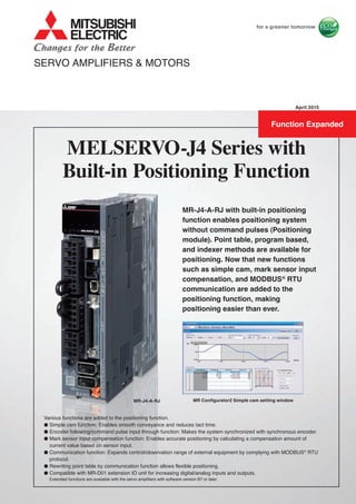
  • 1. MR Configurator2 Simple cam setting window MR-J4-A-RJ with built-in positioning function enables positioning system without command pulses (Positioning module). Point table, program based, and indexer methods are available for positioning. Now that new functions such as simple cam, mark sensor input compensation, and MODBUS® RTU communication are added to the positioning function, making positioning easier than ever. MR-J4-A-RJ MELSERVO-J4 Series with Built-in Positioning Function SERVO AMPLIFIERS & MOTORS Various functions are added to the positioning function. ● Simple cam function: Enables smooth conveyance and reduces tact time. ● Encoder following/command pulse input through function: Makes the system synchronized with synchronous encoder. ● Mark sensor input compensation function: Enables accurate positioning by calculating a compensation amount of current value based on sensor input. ● Communication function: Expands control/observation range of external equipment by complying with MODBUS® RTU protocol. ● Rewriting point table by communication function allows flexible positioning. ● Compatible with MR-D01 extension IO unit for increasing digital/analog inputs and outputs. Extended functions are available with the servo amplifiers with software version B7 or later. April 2015 Function Expanded
  • 2. 1 Rotary servo motor, linear servo motor, and direct drive servo motor are compatible. Positioning operation with point table, program based, and indexer (turret) methods became capable by built-in positioning function in MR-J4-A-RJ*1 , allowing to configure positioning system without command pulses (Positioning module). Positioning command is executed by input/output signals or RS-422/RS-485 communication (up to 32 axis). The positioning data can be set from MR Configurator2*2 easily. Easy setting of from MR Configurator2. Built-in positioning function ● Point table method ● Program method ● Indexer (turret) method Fully closed loop control is also available with point table and program based methods. MR-J4-A-RJ MR-J4-A-RJ Station No. 0 Station No. 1 Station No. 2 Station No. 3 Station No. 4 Station No. 5 Station No. 6 Station No. 7 *1. Use MR-J4-A-RJ servo amplifiers with software version B3 or later when using the positioning function. *2. Be sure to update your MR Configurator2 to the latest version. * Point table can be set with push buttons on the servo amplifier or MR-PRU03 parameter unit along with MR Configurator2. Personal computer Example of a setting display (point table) Setting position data (target position), servo motor speed, and acceleration/deceleration time constants in point table is as easy as setting a parameter. Up to 255 points are settable for the point table. The positioning operation is performed with a start signal after selecting the point table No. Point table method* Create positioning programs with dedicated commands. The positioning operation is performed with a start signal after selecting the program No. The program method enables more complex positioning operation than the point table method. Maximum of 256 programs are registerable. (The total number of steps of each program: 640) Program method* Positioning operation is performed by specifying equally divided stations (up to 255 stations). By setting the number of equally divided stations, the travel distance will be calculated automatically. The positioning operation is performed with a start signal after selecting the station position No. In addition to rotation direction specifying indexer and shortest rotating indexer, backlash compensation and digital override function are also available. * Fully closed loop control mode and linear servo motor control mode are not available with the indexer (turret) method. * MR Configurator2 is required to create programs. Indexer (turret) method* Program example 256 programs max SPN (3000) STC (20) MOV (1000) TIM (100) FOR (3) (1) MOVI (100) (2) TIM (100) (3) NEXT STOP Point table example Operation Speed 2000 1600 1000 20000Position address Point table No. 1 Point table No. 2 Start signal Point table No. Position data Servo motor speed Acceleration time constant Deceleration time constant Sub function Dwell M code 1 2 255 1000 2000 3000 2000 1600 3000 200 100 100 200 100 100 0 0 0 1 0 2 1 2 99 Program No. 1 3000 Start signal Operation Speed Acceleration time constant (20 ms) Deceleration time constant (20 ms) Repeats (2) and (3) for the number of times specified by (1). 1Program No. Position address Dwell (100 ms) 0 1100 1200 13001000 Dwell (100 ms) Dwell (100 ms) Dwell (100 ms) Built-in Positioning Function
  • 3. 2 MR-J4-A-RJ Built-in Positioning Function New useful functions are added to the positioning function: simple cam function, encoder following function, command pulse input through function, mark sensor input compensation function, and communication functions (MODBUS® RTU, Point to Point positioning, current position latch function). Apply these useful functions to a wide variety of applications to configure positioning system easily. (Use MR-J4-A-RJ servo amplifier with software version B7 or later.) Mark sensor input compensation function Encoder following function/Command pulse input through function Simple cam function Convenient functions Various patterns of cam data* can be created easily by using MR Configurator2. Command pulse or point table/program start signal can be used as input to the simple cam. The input command will be outputted to the servo motor according to the cam data. * Cam curve can be selected from 12 types (constant speed/constant acceleration/5th curve/single hypotenuse/cycloid/distorted trapezoid/distorted sine/distorted constant speed/trapecloid/reverse trapecloid/double hypotenuse/reverse double hypotenuse). For details of simple cam function, refer to p.18 in this catalog. Input Switch Outputinput MR-J4-A-RJ Cam data Point table/ Program Point table/ program start signal Command pulse (Synchronous encoder, etc.) Create and set by MR Configurator2 Personal computer Servo motor Transfer specified cam No. from controller through MODBUS® RTU With the encoder following function, the servo amplifier receives A/B-phase output signal from the synchronous encoder as command pulse, and the input command will be outputted to the servo motor according to the cam data. By setting cam data that matches with sheet length, a diameter of the rotary knife axis, and synchronous section of the sheet; a system in which the conveyor axis and the rotary knife axis are synchronized can be configured. Up to 4 Mpulses/s of input from synchronous encoder is compatible with the servo amplifier. The command pulse input through function allows the first axis to output A/B-phase pulses which are received from the synchronous encoder to the next axis, enabling a system the second and later axes are synchronized with the synchronous encoder. Inverter (Drives conveyor axis by speed control) Cutting length set MR-J4-A-RJ MR-J4-A-RJ Servo motor Synchronous encoder A/B-phase pulse A/B-phase pulse Rotary knife axis Conveyor axis Servo motor The actual position of the servo motor can be obtained based on the inputs from the sensor that detects the registration marks printed on the high-speed moving film. The servo amplifier calculates compensation amounts and corrects position errors of the rotary knife axis based on those inputs from the sensor so that the film can be cut at the set position. Conveyor axis Mark sensor (1) Turns on the cam position compensation request by detection of mark sensor (2) Calculates a compensation amount in the servo amplifier (3) Compensates rotary knife axis Inverter (Drives conveyor axis by speed control) Cutting length set Servo motor Synchronous encoder A/B-phase pulse Rotary knife axis MR-J4-A-RJ
  • 4. 3 In addition to RS-422 communication (Mitsubishi general-purpose AC servo protocol), RS-485 communication (MODBUS® RTU protocol) is supported. MODBUS® RTU protocol is compatible with function code 03h (Read holding registers), etc. Controlling and monitoring the servo amplifier by external devices is possible. Communication function (MODBUS® RTU) By setting target position of point table in advance, up to 255 points of Point to Point positioning are possible. Flexible positioning is possible by rewriting the next target position of point table during operation by using this communication function. Communication function (Point to Point positioning) Write up to 255 point tables before operation Rewrites the next target position during operation MR‐J4‐A‐RJ Personal computer Controller Communication function * RJ-45 junction connector terminal block and RJ-45 compatible cable designed for MR-J4-A-RJ are required. Refer to "Products on the Market" in this catalog. Master device such as PLC Slave device MODBUS® RTU Inverter (FR-A800) Display (GOT2000) Hydrostat Measuring device Compatible function code 03h 08h 10h Read holding registers Diagnostics Preset multiple registers Target position can be compensated by writing point table (target position) based on the data latched by a mark detection function (current position latch*). * When the mark detection signal turns on, a current position will be latched. The latched data can be read by the communication function. Example: Executing positioning compensation when a product is mispositioned by 50 on a handling pallet. Start an operation by specifying point table No.1 (target position: 1000). Communication function (current latch) measures a position gap with the mark detection function and writes the position gap of 50 to the target position in point table No.2 for compensation during operation. After the operation is complete, the product stops with the position gap of 50. When an operation is started, by specifying point table No.2, the product moves by 50, and it will be set to the right position. Communication function (current position latch) No position gap Target position: 1000 Compensation positioning Target position: 50 Product position: 1000 Product position: 950 Writes compensation position With position gap 50 Position gap: 50 Point table No. Target position Servo motor speed … 1000 3000 2000 3000 For fixing For communication - -3000 3000 1 2 … … … 255 Point table No. Target position Servo motor speed … 1000 3000 0 3000 For compensation - -1 2 Target position Servo motor speed … 1000 3000 50 3000 For compensation 1 2 Over 255 target positions are available by rewriting the target position Point table No.
  • 5. MR-J4-A-RJ Built-in Positioning Function 4 MR-J4-A-RJ Built-in Positioning Function MR-J4-A-RJ Positioning Function: Point Table Method Positioning operation is executed by selecting the point table No. with a command interface signal according to the position and speed data set in the point table. Item Description Command method Command interface Input: 11 points excluding EM2 (Forced stop 2), output: 8 points RS-422 communication/RS-485 communication (Note 3) Operating specification Positioning by specifying the point table No. (255 points) Position command input (Note 1) Absolute value command method Set in the point table. Setting range of feed length per point: -999999 to 999999 [×10STM μm], -99.9999 to 99.9999 [×10STM inch], -999999 to 999999 [pulse], Setting range of rotation angle: -360.000 to 360.000 [degree] Incremental value command method Set in the point table. Setting range of feed length per point: 0 to 999999 [×10STM μm], 0 to 99.9999 [×10STM inch], 0 to 999999 [pulse], Setting range of rotation angle: 0 to 999.999 [degree] Speed command input Set the acceleration/deceleration time constants in the point table. Set the S-pattern acceleration/deceleration time constants with [Pr. PC03]. System Signed absolute value command method, incremental value command method Analog override 0 V DC to ±10 V DC/0% to 200% Torque limit Set by parameters or external analog input (0 V DC to +10 V DC/maximum torque) Operation mode Automatic operation mode Each positioning operation Point table No. input, position data input method Each positioning operation is executed based on the position/speed commands. Automatic continuous positioning operation Varying-speed operation (2 to 255 speeds), automatic continuous positioning operation (2 to 255 points) Manual operation mode JOG operation Inching operation is executed with input signal or serial communication function (Note 3) according to the speed command set with a parameter. Manual pulse generator operation Manual feeding is executed with a manual pulse generator. Command pulse multiplication: select from ×1, ×10, and ×100 with a parameter. Home position return mode Dog type Returns to home position upon Z-phase pulse after passing through proximity dog. Home position return direction selectable, home position shift distance settable, home position address settable, automatic retract on dog back to home position, automatic stroke retract function Count type Returns to home position upon the encoder pulse count after touching proximity dog. Home position return direction selectable, home position shift distance settable, home position address settable, automatic retract on dog back to home position, automatic stroke retract function Data set type Returns to home position without dog. Any position settable as a home position using manual operation, etc. Home position address settable Stopper type Returns to home position upon hitting the stroke end. Home position return direction selectable, home position address settable Home position ignorance (servo-on position as home position) Sets a home position where SON (Servo-on) signal turns on. Home position address settable Dog type rear end reference Returns to home position with reference to the rear end of proximity dog. Home position return direction selectable, home position shift distance settable, home position address settable, automatic retract on dog back to home position, automatic stroke retract function Count type front end reference Returns to home position with reference to the front end of proximity dog. Home position return direction selectable, home position shift distance settable, home position address settable, automatic retract on dog back to home position, automatic stroke retract function Dog cradle type Returns to home position upon the first Z-phase pulse with reference to the front end of proximity dog. Home position return direction selectable, home position shift distance settable, home position address settable, automatic retract on dog back to home position, automatic stroke retract function Dog type adjacent Z-phase reference (Note 2) Returns to home position upon the last Z-phase pulse with reference to the front end of proximity dog. Home position return direction selectable, home position shift distance settable, home position address settable, automatic retract on dog back to home position, automatic stroke retract function Dog type front end reference Returns to home position to the front end of dog with reference to the front end of proximity dog. Home position return direction selectable, home position shift distance settable, home position address settable, automatic retract on dog back to home position, automatic stroke retract function Dogless Z-phase reference (Note 2) Returns to home position to Z-phase pulse with reference to the first Z-phase pulse. Home position return direction settable, home position shift distance settable, home position address settable Automatic positioning to home position function High-speed automatic positioning to a defined home position Other functions Absolute position detection, backlash compensation, overtravel prevention with external limit switches (LSP/ LSN), teaching function, roll feed display function, software stroke limit, mark detection (current position latch/interrupt positioning/mark sensor input compensation), simple cam function, encoder following function, command pulse input through function, infinite feed function (setting degree), analog override function Notes: 1. STM is the ratio to the setting value of the position data. STM can be changed with [Pr. PT03]. 2. Home position return modes of dog type adjacent Z-phase reference and dogless Z-phase reference are not available when the direct drive motor or incremental type linear encoder is used. 3. Compatible with Mitsubishi general-purpose AC servo protocol (RS-422/RS-485 communication) and MODBUS® RTU protocol (RS-485 communication).
  • 6. 5 MR-J4-A-RJ Positioning Function: Point Table Method Absolute value command method: travels to a specified address (absolute value) with reference to the home position Item Setting range Description Point table No. 1 to 255 Specify a point table in which a target position, servo motor speed, acceleration/deceleration time constants, dwell, and sub function will be set. Target position (Note 1, 3) (position data) -999999 to 999999 [×10STM μm] -99.9999 to 99.9999 [×10STM inch] -360.000 to 360.000 [degree] -999999 to 999999 [pulse] Set a travel distance. (1) When using as absolute value command method Set a target address (absolute value). (2) When using as incremental value command method Set a travel distance. Reverse rotation command is applied with a minus sign. Servo motor speed (Note 2) 0 to permissible speed [r/min] [mm/s] Set a command speed for the servo motor in positioning. Acceleration time constant 0 to 20000 [ms] Set a time period for the servo motor to reach the rated speed. Deceleration time constant 0 to 20000 [ms] Set a time period for the servo motor to decelerate from the rated speed to a stop. Dwell 0 to 20000 [ms] Set dwell. When the dwell is set, the position command for the next point table will be started after the position command for the selected point table is completed and the set dwell is passed. The dwell is disabled when 0 or 2 is set for the sub function. Varying-speed operation is enabled when 1, 3, 8, 9, 10, or 11 is set for the sub function and when 0 is set for the dwell. Sub function 0 to 3, and 8 to 11 Set sub function. (1) When using as absolute value command method 0: Executes automatic operation for a selected point table. 1: Executes automatic continuous operation without stopping for the next point table. 8: Executes automatic continuous operation without stopping for the point table selected at the start. 9: Executes automatic continuous operation without stopping for the point table No. 1. (2) When using as incremental value command method 2: Executes automatic operation for a selected point table. 3: Executes automatic continuous operation without stopping for the next point table. 10: Executes automatic continuous operation without stopping for the point table selected at the start. 11: Executes automatic continuous operation without stopping for the point table No. 1. M code 0 to 99 Set a code to be outputted when the positioning completes. Notes: 1. Change the unit to μm/inch/degree/pulse with [Pr. PT01]. 2. The speed unit is r/min for the rotary servo motors and the direct drive motors, and mm/s for the linear servo motors. 3. STM is the ratio to the setting value of the position data. STM can be changed with [Pr. PT03]. Example of setting point table data Point table No. Target position (position data) [× 10STM μm] (Note 1) Servo motor speed [r/min] Acceleration time constant [ms] Deceleration time constant [ms] Dwell [ms] Sub function M code 1 1000 2000 200 200 0 ✽ 1 2 2000 1600 100 100 0 0 2 : : : : : : : : 255 3000 3000 100 100 0 2 99 ✽ The operation of the next point table is set with the sub function. Speed Position address Start signal M code Point table No. 1 Point table No. 2 M code data No. 1 0 1000 2000 Time When the sub function is set to 1:●● Automatic continuous operation is executed based on the point table. When the sub function is set to 0:●● Start signal is required for each point table. Notes: 1. STM is the ratio to the setting value of the position data. STM can be changed with [Pr. PT03]. Position address Start signal M code Speed Point table No. 1 Point table No. 2 10000 1000 2000 M code data No. 1 M code data No. 2 Time
  • 7. MR-J4-A-RJ Built-in Positioning FunctionMR-J4-A-RJ Built-in Positioning Function 6 MR-J4-A-RJ Positioning Function: Point Table Method Incremental value command method: travels from a current position according to the set position data Item Setting range Description Point table No. 1 to 255 Specify a point table in which a target position, servo motor speed, acceleration/deceleration time constants, dwell, and sub function will be set. Target position (Note 1, 3) (position data) 0 to 999999 [×10STM μm] 0 to 99.9999 [×10STM inch] 0 to 999.999 [degree] 0 to 999999 [pulse] Set a travel distance. Operation starts with ST1 (Forward rotation start) or ST2 (Reverse rotation start). Servo motor speed (Note 2) 0 to permissible speed [r/min] [mm/s] Set a command speed for the servo motor in positioning. Acceleration time constant 0 to 20000 [ms] Set a time period for the servo motor to reach the rated speed. Deceleration time constant 0 to 20000 [ms] Set a time period for the servo motor to decelerate from the rated speed to a stop. Dwell 0 to 20000 [ms] Set a dwell. When the dwell is set, the position command for the next point table will be started after the position command for the selected point table is completed and the set dwell is passed. The dwell is disabled when 0 is set for the sub function. Varying-speed operation is enabled when 1, 8, or 9 is set for the sub function and when 0 is set for the dwell. Sub function 0, 1, 8, and 9 Set sub function. 0: Executes automatic operation for the selected point table. 1: Executes automatic continuous operation without stopping for the next point table. 8: Executes automatic continuous operation without stopping for the point table selected at the start. 9: Executes automatic continuous operation without stopping for the point table No. 1. M code 0 to 99 Set a code to be outputted when the positioning completes. Notes: 1. Change the unit to μm/inch/degree/pulse with [Pr. PT01]. 2. The speed unit is r/min for the rotary servo motors and the direct drive motors, and mm/s for the linear servo motors. 3. STM is the ratio to the setting value of the position data. STM can be changed with [Pr. PT03]. Example of setting point table data Point table No. Target position (position data) [× 10STM μm] (Note 1) Servo motor speed [r/min] Acceleration time constant [ms] Deceleration time constant [ms] Dwell [ms] Sub function M code 1 1000 2000 200 200 0 ✽ 1 2 1000 1600 100 100 0 0 2 : : : : : : : : 255 3000 3000 100 100 0 0 99 ✽ The operation of the next point table is set with the sub function. Speed Position address Start signal M code Point table No. 1 Point table No. 2 M code data No. 1 0 1000 2000 Time When the sub function is set to 1:●● Automatic continuous operation is executed based on the point table. When the sub function is set to 0:●● Start signal is required for each point table. Notes: 1. STM is the ratio to the setting value of the position data. STM can be changed with [Pr. PT03]. Position address Start signal M code Speed Point table No. 1 Point table No. 2 10000 1000 2000 M code data No. 1 M code data No. 2 Time
  • 8. 7 MR-J4-A-RJ Standard Wiring Diagram Example: Point Table Method CN5 CN8 CN2L CN2 L1 L2 L3 L11 L21 P15R 1 VC 2 27 LG TLA 28 SD EM2 42 DI3 (Note 6) 35 DI2 (Note 6) 10 SON 15 MD0 16 18 ST1 ST2 DOG LSP 17 45 43 LSN 44 DI0 19 DI1 41 DOCOM 47 DICOM 21 ALM 48 ZP 23 MEND 25 CPO 22 24INP 49RD 13 14 DICOM DOCOM 20 OPC 12 46 8 9 4 5 6 LZ 7 LZR LA 34 LAR 33 LB LBR LG OP SD CN6 CN3 SDP SDN RDP RDN LG LG TRE 5 4 3 6 1 7 8 RDP RDN SDP SDN GND GND RS-422 MO13 LG1 MO22 R A 1 R A 2 R A 3 R A 4 R A 5 R A 6 CN1 U V W CN4 BAT LG 1 2 Mount an optional battery (MR-BAT6V1SET), or a battery case (MR-BT6VCASE) and batteries (MR-BAT6V1) for absolute position detection system. Encoder Z-phase pulse (differential line driver) Encoder Z-phase pulse (Open collector) Encoder A-phase pulse (differential line driver) Encoder B-phase pulse (differential line driver) Control common Control common 24 V DC power supply for interface 2 m or shorter 10 m or shorter Main circuit power supply (Note 4) (Note 2) Forced stop 2 Servo-on Operation mode selection 1 Forward rotation start Reverse rotation start Proximity dog Forward rotation stroke end Reverse rotation stroke end Point table No. selection 1 Point table No. selection 2 Point table No. selection 3 Point table No. selection 4 10 m or shorter 30 m or shorter 10 m or shorter 2 m or shorter Malfunction Rough match Travel completion Home position return In-position Ready Preliminary output signal Analog torque limit +10 V/maximum torque Upper limit setting Upper limit setting Plate (Note 5) (Note 5) (Note 8) (Note 1) (Note 3)Plate Main circuit power supply Control circuit power supply Servo amplifier MR-J4-A-RJ Servo motor connection The connection differs according to each servo motor. Refer to Servo Motor Connection Example in MELSERVO-J4 catalog (L(NA)03058). Encoder cable Power cable Servo motor CN8 connector connection Refer to STO I/O Signal Connector (CN8) Connection Example in MELSERVO-J4 catalog (L(NA)03058). CN2L connector connection Refer to MELSERVO-J4 catalog (L(NA)03058) for the connection. Setup software MR Configurator2 Parameter unit MR-PRU03 (Note 7) Personal computer USB cable MR-J3USBCBL3M Analog monitor output Output voltage: ±10 V Maximum output current: 1 mA Output voltage: ±10 V Maximum output current: 1 mA 2 m or shorter Main/control circuit power supply connection The connection differs according to the power voltage. Refer to Main/Control Circuit Power Supply Connection Example in MELSERVO-J4 catalog (L(NA)03058). Analog override ±10 V/0% to 200% Notes: 1. It is also possible to connect a personal computer to CN3 connector with an RS-422/RS-232C conversion cable. However, USB interface (CN5 connector) and RS-422 interface (CN3 connector) are mutually exclusive. Do not use them at the same time. Refer to Products on the Market for Servo Amplifiers in MELSERVO-J4 catalog (L(NA)03058) for the RS-422/RS-232C conversion cable. Refer to MR-J4-_A_-RJ Servo Amplifier Instruction Manual (Modbus-RTU communication) for RS-485 communication cable connection diagram. 2. This is for sink wiring. Source wiring is also possible. However, when input devices are assigned to CN1-10 pin and CN1-35 pin, be sure to use sink wiring. Source wiring is not possible in this case. In the positioning mode, input devices are assigned in the initial setting. Refer to MR-J4-_A_-RJ Servo Amplifier Instruction Manual (Positioning Mode) for details. 3. Be sure to attach a short-circuit connector supplied with the servo amplifier when the STO function is not used. 4. To prevent an unexpected restart of the servo amplifier, create a circuit to turn off EM2 (Forced stop 2) when the main circuit power is turned off. 5. No output device is assigned in the initial setting. Assign an output device with [Pr. PD47] as necessary. 6. DI2 and DI3 are assigned to CN1-10 pin and CN1-35 pin respectively in the initial setting. Change them with [Pr. PD44] and [Pr. PD46] when using a manual pulse generator. 7. Use a commercial LAN cable (EIA568 compliant), and keep the wiring distance within 10 m when using MR-PRU03 parameter unit. 8. Assign the output devices mentioned to CN1-22 pin, CN1-23 pin, and CN1-25 pin with [Pr. PD23], [Pr. PD24] and [Pr. PD26]. Be sure to read through Instruction Manual for the actual wiring and use. Use the equipment after you have a full knowledge of the equipment, safety information and instructions.
  • 9. MR-J4-A-RJ Built-in Positioning FunctionMR-J4-A-RJ Built-in Positioning Function 8 MR-J4-A-RJ Positioning Function: Program Method Positioning operation is executed by selecting programs with command signals. The programs including position data, servo motor speed, acceleration/deceleration time constants and others need to be created beforehand. The program method enables more complex positioning operation than the point table method. MR Configurator2 is required to create programs. Item Description Command method Command interface Input: 11 points excluding EM2 (Forced stop 2), output: 8 points RS-422 communication/RS-485 communication (Note 3) Operating specification Program language (program with MR Configurator2) Program capacity: 640 steps (256 programs) Position command input (Note 1) Absolute value command method Set with program language. Setting range of feed length: -999999 to 999999 [×10STM μm], -99.9999 to 99.9999 [×10STM inch], -999999 to 999999 [pulse], Setting range of rotation angle: -360.000 to 360.000 [degree] Incremental value command method Set with program language. Setting range of feed length: -999999 to 999999 [×10STM μm], -99.9999 to 99.9999 [×10STM inch], -999999 to 999999 [pulse], Setting range of rotation angle: -999.999 to 999.999 [degree] Speed command input Set servo motor speed, acceleration/deceleration time constants, S-pattern acceleration/ deceleration time constants with program language. S-pattern acceleration/deceleration time constants are also settable with [Pr. PC03]. System Signed absolute value command method/signed incremental value command method Analog override 0 V DC to ±10 V DC/0% to 200% Torque limit Set by parameters or external analog input (0 V DC to +10 V DC/maximum torque) Operation mode Automatic operation mode Program Depends on the setting of the program language Manual operation mode JOG operation Inching operation is executed with input signal or serial communication function (Note 3) according to the speed command set with a parameter. Manual pulse generator operation Manual feeding is executed with a manual pulse generator. Command pulse multiplication: select from ×1, ×10, and ×100 with a parameter. Home position return mode Dog type Returns to home position upon Z-phase pulse after passing through proximity dog. Home position return direction selectable, home position shift distance settable, home position address settable, automatic retract on dog back to home position, automatic stroke retract function Count type Returns to home position upon the encoder pulse count after touching proximity dog. Home position return direction selectable, home position shift distance settable, home position address settable, automatic retract on dog back to home position, automatic stroke retract function Data set type Returns to home position without dog. Any position settable as a home position using manual operation, etc. Home position address settable Stopper type Returns to home position upon hitting the stroke end. Home position return direction selectable, home position address settable Home position ignorance (servo-on position as home position) Sets a home position where SON (Servo-on) signal turns on. Home position address settable Dog type rear end reference Returns to home position with reference to the rear end of proximity dog. Home position return direction selectable, home position shift distance settable, home position address settable, automatic retract on dog back to home position, automatic stroke retract function Count type front end reference Returns to home position with reference to the front end of proximity dog. Home position return direction selectable, home position shift distance settable, home position address settable, automatic retract on dog back to home position, automatic stroke retract function Dog cradle type Returns to home position upon the first Z-phase pulse with reference to the front end of proximity dog. Home position return direction selectable, home position shift distance settable, home position address settable, automatic retract on dog back to home position, automatic stroke retract function Dog type adjacent Z-phase reference (Note 2) Returns to home position upon the last Z-phase pulse with reference to the front end of proximity dog. Home position return direction selectable, home position shift distance settable, home position address settable, automatic retract on dog back to home position, automatic stroke retract function Dog type front end reference Returns to home position to the front end of dog with reference to the front end of proximity dog. Home position return direction selectable, home position shift distance settable, home position address settable, automatic retract on dog back to home position, automatic stroke retract function Dogless Z-phase reference (Note 2) Returns to home position to Z-phase pulse with reference to the first Z-phase pulse. Home position return direction settable, home position shift distance settable, home position address settable Automatic positioning to home position function High-speed automatic positioning to a defined home position Other functions Absolute position detection, backlash compensation, overtravel prevention with external limit switches (LSP/LSN), roll feed display function, software stroke limit, mark detection (current position latch/ interrupt positioning/mark sensor input compensation), simple cam function, encoder following function, command pulse input through function, infinite feed function (setting degree), analog override function Notes: 1. STM is the ratio to the setting value of the position data. STM can be changed with [Pr. PT03]. 2. Home position return modes of dog type adjacent Z-phase reference and dogless Z-phase reference are not available when the direct drive motor or incremental type linear encoder is used. 3. Compatible with Mitsubishi general-purpose AC servo protocol (RS-422/RS-485 communication) and MODBUS® RTU protocol (RS-485 communication).
  • 10. 9 MR-J4-A-RJ Positioning Function: Program Method Command List Command Name Setting range Description SPN(setting value) (Note 2) Servo motor speed 0 to instantaneous permissible speed [r/min] [mm/s] Set a command speed for the servo motor in positioning. Do not set a value exceeding the instantaneous permissible speed of the servo motor. STA(setting value) (Note 2) Acceleration time constant 0 to 20000 [ms] Set acceleration time constant. The setting value is a time period that the servo motor reaches the rated speed from a stop. STB(setting value) (Note 2) Deceleration time constant 0 to 20000 [ms] Set deceleration time constant. The setting value is a time period that the servo motor stops from the rated speed. STC(setting value) (Note 2) Acceleration/ deceleration time constants 0 to 20000 [ms] Set acceleration and deceleration time constants. The setting value is a time period that the servo motor reaches the rated speed from a stop and stops from the rated speed. STD(setting value) (Note 2) S-pattern acceleration/ deceleration time constants 0 to 1000 [ms] Set S-pattern acceleration/deceleration time constants. MOV(setting value) (Note 4, 5) Absolute value travel command -999999 to 999999 [×10STM μm] -99.9999 to 99.9999 [×10STM inch] -360.000 to 360.000 [degree] -999999 to 999999 [pulse] Travels according to the value set as an absolute value. MOVA(setting value) (Note 4, 5) Absolute value continuous travel command Travels continuously according to the value set as an absolute value. Be sure to write this command after [MOV] command. MOVI(setting value) (Note 4, 5) Incremental value travel command -999999 to 999999 [×10STM μm] -99.9999 to 99.9999 [×10STM inch] -999.999 to 999.999 [degree] -999999 to 999999 [pulse] Travels according to the value set as an incremental value. MOVIA(setting value) (Note 4, 5) Incremental value continuous travel command Travels continuously according to the value set as an incremental value. Be sure to write this command after [MOVI] command. SYNC(setting value) (Note 1) Waiting for external signal to switch on 1 to 3 Stops the next step until PI1 (Program input 1) to PI3 (Program input 3) turn on after SOUT (SYNC synchronous output) is outputted. OUTON(setting value) (Note 1) External signal on output 1 to 3 Turns on OUT1 (Program output 1) to OUT3 (Program output 3). OUTOF(setting value) (Note 1) External signal off output 1 to 3 Turns off OUT1 (Program output 1) to OUT3 (Program output 3) which were turned on with [OUTON] command. TRIP(setting value) (Note 1, 4, 5) Absolute value trip point specification -999999 to 999999 [×10STM μm] -99.9999 to 99.9999 [×10STM inch] -360.000 to 360.000 [degree] -999999 to 999999 [pulse] Executes the next step after [MOV] or [MOVA] commands are started and then the servo motor moves for the travel amount set in [TRIP] command. Be sure to write this command after [MOV] or [MOVA] command. TRIPI(setting value) (Note 1, 4, 5) Incremental value trip point specification -999999 to 999999 [×10STM μm] -99.9999 to 99.9999 [×10STM inch] -999.999 to 999.999 [degree] -999999 to 999999 [pulse] Executes the next step after [MOVI] or [MOVIA] commands are started and then the servo motor moves for the travel amount set in [TRIPI] command. Be sure to write this command after [MOVI] or [MOVIA] command. ITP(setting value) (Note 1, 3, 4, 5) Interrupt positioning Stops the operation after the servo motor moves for the travel amount set when the interrupt signal is inputted. Be sure to write this command after [SYNC] command. COUNT(setting value) (Note 1) External pulse count -999999 to 999999 [pulse] Executes the next step when the value of the pulse counter exceeds the count value set in [COUNT] command. [COUNT (0)] clears the pulse counter to zero. FOR(setting value) NEXT Step repeat command 0, and 1 to 10000 [number of times] Repeats the steps between [FOR (setting value)] and [NEXT] commands for the number of times set. Repeats endlessly with [FOR (0) NEXT]. LPOS (Note 1) Current position latch - Latches the current position with the rising edge of the LPS signal. The latched current position data can be read with the communication command. TIM(setting value) Dwell 1 to 20000 [ms] Waits for the next step until the set time passes. ZRT Home position return - Executes a manual home position return. TIMES(setting value) Program count command 0, and 1 to 10000 [number of times] Set the number of program execution by writing [TIMES (setting value)] command in the first line of the program. The setting is not required for executing once. Repeats endlessly with [TIMES (0)]. STOP Program stop - Stops the program in execution. Be sure to write this command in the final line. Notes: 1. [SYNC], [OUTON], [OUTOF], [TRIP], [TRIPI], [ITP], [COUNT], and [LPOS] commands are valid while the commands are outputted. 2. [SPN] command is valid while [MOV], [MOVA], [MOVI], or [MOVIA] command is in execution. [STA], [STB], [STC], and [STD] commands are valid while [MOV] or [MOVI] command is in execution. 3. [ITP] command will be skipped to the next step when the remaining distance equals to or less than the setting value, when the servo motor is not running, or when the servo motor is decelerating. 4. Change the unit to μm/inch/degree/pulse with [Pr. PT01]. 5. STM is the ratio to the setting value of the position data. STM can be changed with [Pr. PT03].
  • 11. MR-J4-A-RJ Built-in Positioning FunctionMR-J4-A-RJ Built-in Positioning Function 10 MR-J4-A-RJ Positioning Function: Program Method Notes: 1. The values in [SPN], [STA], [STB], and [STC] commands remains valid until they are reset. The values will not be initialized at the start of the program. The settings are also valid in other programs. Position address Servo motor speed 0 1000 1000 2500 (4) Absolute value travel command (1000 × 10STM [µm]) (5) Dwell (100 [ms]) (1) Speed (3000 [r/min]) (1) Speed (3000 [r/min]) (2) Acceleration time constant (200 [ms]) (3) Deceleration time constant (300 [ms]) (2) Acceleration time constant (200 [ms]) (3) Deceleration time constant (300 [ms]) (6) Absolute value travel command (2500 × 10STM [µm]) Program example 1 The following is an example of executing two types of operations with the same servo motor speed and acceleration/deceleration time constants but the different travel commands. Step Program (Note 1) Description (1) SPN(3000) Servo motor speed: 3000 [r/min] (2) STA(200) Acceleration time constant: 200 [ms] (3) STB(300) Deceleration time constant: 300 [ms] (4) MOV(1000) Absolute value travel command: 1000 [×10STM μm] (5) TIM(100) Dwell: 100 [ms] (6) MOV(2500) Absolute value travel command: 2500 [×10STM μm] (7) STOP Program stop Command list Command Name Setting range Description TLP(setting value) Forward rotation torque limit 0, and 1 to 1000 [0.1%] Limits the torque generated by the servo motor driving in CCW and regenerating in CW, as the maximum torque is 100%. The setting remains valid until the program is stopped. [TLP (0)] enables the setting of [Pr. PA11]. TLN(setting value) Reverse rotation torque limit 0, and 1 to 1000 [0.1%] Limits the torque generated by the servo motor driving in CW and regenerating in CCW, as the maximum torque is 100%. The setting remains valid until the program is stopped. [TLN (0)] enables the setting of [Pr. PA12]. TQL(setting value) Torque limit 0, and 1 to 1000 [0.1%] Limits the torque generated by the servo motor, as the maximum torque is 100%. The setting remains valid until the program is stopped. [TQL (0)] enables the settings of [Pr. PA11] and [Pr. PA12]. Program example 2 The following is an example of repeating the steps between [FOR (setting value)] and [NEXT] commands for the number of times set. Step Program (Note 1) Description (1) SPN(3000) Servo motor speed: 3000 [r/min] (2) STC(20) Acceleration/deceleration time constants: 20 [ms] (3) MOV(1000) Absolute value travel command: 1000 [×10STM μm] (4) TIM(100) Dwell: 100 [ms] (5) FOR(3) Starting the step repeat command: 3 [number of times] (6) MOVI(100) Incremental value travel command: 100 [×10STM μm] (7) TIM(100) Dwell: 100 [ms] (8) NEXT Ending the step repeat command (9) STOP Program stop (4) Dwell (100 [ms]) (7) Dwell (100 [ms]) (2) Acceleration time constant (20 [ms]) (2) Deceleration time constant (20 [ms]) 0 1000 1100 13001200 Steps (6) and (7) are repeated for the number of times specified by step (5). Position address Servo motor speed (1) Speed (3000 [r/min]) (6) Incremental value travel command(100 × 10STM [µm]) (3) Absolute value travel command (1000 × 10STM [µm])
  • 12. 11 MR-J4-A-RJ Standard Wiring Diagram Example: Program Method Control circuit power supply USB cable MR-J3USBCBL3M CN5 CN8 CN2L CN2 L1 L2 L3 L11 L21 P15R 1 VC 2 27 LG TLA 28 SD EM2 42 35 10 SON 15 MD0 16 18 ST1 ST2 DOG LSP 17 45 43 LSN 44 DI0 19 DI1 41 DOCOM 47 DICOM 21 ALM 48 ZP 23 MEND 25 CPO 22 24INP 49RD 13 14 DICOM DOCOM 20 46 8 9 4 5 6 LZ 7 LZR LA 34 LAR 33 LB LBR LG OP SD CN6 CN3 SDP SDN RDP RDN LG LG TRE 5 4 3 6 1 7 8 RDP RDN SDP SDN GND GND RS-422 MO13 LG1 MO22 R A 1 R A 2 R A 3 R A 4 R A 5 R A 6 CN1 U V W Main/control circuit power supply connection The connection differs according to the power voltage. Refer to Main/Control Circuit Power Supply Connection Example in MELSERVO-J4 catalog (L(NA)03058). Encoder Z-phase pulse (differential line driver) Encoder Z-phase pulse (Open collector) Encoder A-phase pulse (differential line driver) Encoder B-phase pulse (differential line driver) Control common Control common 24 V DC power supply for interface Main circuit power supply 2 m or shorter 10 m or shorter 10 m or shorter 10 m or shorter Main circuit power supply (Note 4) Forced stop 2 Servo-on Operation mode selection Forward rotation start Reverse rotation start Proximity dog Forward rotation stroke end Reverse rotation stroke end Program No. selection 1 Program No. selection 2 Program No. selection 3 Program No. selection 4 Malfunction Rough match Travel completion Home position return In-position Ready Preliminary output signal (Note 9) Analog torque limit +10 V/maximum torque Upper limit setting Upper limit setting Analog override ±10 V/0% to 200% 2 m or shorter Plate (Note 5) (Note 5) DI3 (Note 6) DI2 (Note 6) (Note 2) Plate Setup software MR Configurator2 Personal computer Analog monitor output Output voltage: ±10 V Maximum output current: 1 mA Output voltage: ±10 V Maximum output current: 1 mA 2 m or shorter 30 m or shorter (Note 1) (Note 3) CN8 connector connection Refer to STO I/O Signal Connector (CN8) Connection Example in MELSERVO-J4 catalog (L(NA)03058). CN2L connector connection Refer to MELSERVO-J4 catalog (L(NA)03058) for the connection. Encoder cable Power cable Servo motor Servo motor connection The connection differs according to each servo motor. Refer to Servo Motor Connection Example in MELSERVO-J4 catalog (L(NA)03058). Servo amplifier MR-J4-A-RJ Parameter unit MR-PRU03 (Note 7, 8) CN4 BAT LG 1 2 Mount an optional battery (MR-BAT6V1SET), or a battery case (MR-BT6VCASE) and batteries (MR-BAT6V1) for absolute position detection system. OPC 12 Notes: 1. It is also possible to connect a personal computer to CN3 connector with an RS-422/RS-232C conversion cable. However, USB interface (CN5 connector) and RS-422 interface (CN3 connector) are mutually exclusive. Do not use them at the same time. Refer to Products on the Market for Servo Amplifiers in MELSERVO-J4 catalog (L(NA)03058) for the RS-422/RS-232C conversion cable. Refer to MR-J4-_A_-RJ Servo Amplifier Instruction Manual (Modbus-RTU communication) for RS-485 communication cable connection diagram. 2. This is for sink wiring. Source wiring is also possible. However, when input devices are assigned to CN1-10 pin and CN1-35 pin, be sure to use sink wiring. Source wiring is not possible in this case. In the positioning mode, input devices are assigned in the initial setting. Refer to MR-J4-_A_-RJ Servo Amplifier Instruction Manual (Positioning Mode) for details. 3. Be sure to attach a short-circuit connector supplied with the servo amplifier when the STO function is not used. 4. To prevent an unexpected restart of the servo amplifier, create a circuit to turn off EM2 (Forced stop 2) when the main circuit power is turned off. 5. No output device is assigned in the initial setting. Assign an output device with [Pr. PD47] as necessary. 6. DI2 and DI3 are assigned to CN1-10 pin and CN1-35 pin respectively in the initial setting. Change them with [Pr. PD44] and [Pr. PD46] when using a manual pulse generator. 7. Use a commercial LAN cable (EIA568 compliant), and keep the wiring distance within 10 m when using MR-PRU03 parameter unit. 8. Programs cannot be edited with the parameter unit. 9. Assign the output devices mentioned to CN1-22 pin, CN1-23 pin, and CN1-25 pin with [Pr. PD23], [Pr. PD24] and [Pr. PD26]. Be sure to read through Instruction Manual for the actual wiring and use. Use the equipment after you have a full knowledge of the equipment, safety information and instructions.
  • 13. MR-J4-A-RJ Built-in Positioning FunctionMR-J4-A-RJ Built-in Positioning Function 12 MR-J4-A-RJ Positioning Function: Indexer (Turret) Method Positioning is executed by specifying stations (maximum of 255 stations). Travel distance is automatically calculated with parameters by setting the numbers of stations. Item Description Command method Command interface Input: 11 points excluding EM2 (Forced stop 2), output: 8 points RS-422 communication/RS-485 communication (Note 1) Operating specification Positioning by specifying the station position The maximum number of divisions: 255 Speed command input Selects the rotation speed and acceleration/deceleration time by input signal System Rotation direction specifying indexer, shortest rotating indexer Digital override Selects the override multiplying factor by input signal Torque limit Set by parameters or external analog input (0 V DC to +10 V DC/maximum torque) Operation mode Automatic operation mode Rotation direction specifying indexer Positions to the specified station. Rotation direction settable Shortest rotating indexer Positions to the specified station. Rotates in the shorter direction from the current position. Manual operation mode JOG operation Decelerates to a stop regardless of the station Station JOG operation Rotates in a direction specified by the rotation direction decision when the start signal turns on. Positions to the nearest station where the servo motor can decelerate to a stop when the start signal turns off. Home position return mode Torque limit changing dog type Returns to home position upon Z-phase pulse after passing through the front end of proximity dog. Home position return direction selectable, home position shift distance settable, home position address settable, torque limit automatic switching function Torque limit changing data set type Returns to home position without dog. Any position settable as home position, home position address settable, torque limit automatic switching function Other functions Absolute position detection system, backlash compensation, overtravel prevention with external limit switches (LSP/LSN), digital override function Notes: 1. Compatible with Mitsubishi general-purpose AC servo protocol (RS-422/RS-485 communication) and MODBUS® RTU protocol (RS-485 communication).
  • 14. 13 MR-J4-A-RJ Positioning Function: Indexer (Turret) Method Rotation direction specifying indexer In the rotation direction specifying indexer, the servo motor always rotates in a definite direction. Turn off MD0 (Operation mode selection 1), and turn on MD1 (Operation mode selection 2). The servo motor moves in the station No. decreasing direction with SIG (Rotation direction decision) off, and in the increasing direction with SIG on. When ST1 (Forward rotation direction) turns on, the travel amount will be calculated from the current position and the next station position, and then the positioning will be executed to the direction specified by the rotation direction decision. The following timing chart is an example of the operation executed from the station No. 0 where the servo motor is stopped at servo-on. Shortest rotating indexer In the shortest rotating indexer, the servo motor automatically rotates in the shorter direction. Turn on both MD0 (Operation mode selection 1) and MD1 (Operation mode selection 2). When ST1 (Forward rotation direction) turns on, the travel amount will be calculated from the current position and the next station position, and then the positioning will be executed in the shorter direction. The following timing chart is an example of the operation executed from the station No. 0 where the servo motor is stopped at servo-on. Next station position Automatic operation speed 1 No. 1 The number of stations: 8 MEND (Travel completion) Next station position input Servo motor speed ST1 (Forward rotation start) MD0 (Operation mode selection 1) MD1 (Operation mode selection 2) ON OFF ON OFF ON OFF ON OFF SIG (Rotation direction decision) ON OFF Station position No. 1 0 1 2 3 4 5 6 7 Next station position Automatic operation speed 1 No. 1 ON OFF ON OFF ON OFF ON OFF Station position No. 1 0 1 2 3 4 5 6 7 The number of stations: 8 MEND (Travel completion) Next station position input Servo motor speed ST1 (Forward rotation start) MD0 (Operation mode selection 1) MD1 (Operation mode selection 2)
  • 15. MR-J4-A-RJ Built-in Positioning FunctionMR-J4-A-RJ Built-in Positioning Function 14 MR-J4-A-RJ Standard Wiring Diagram Example: Indexer (Turret) Method (Note 2) CN5 CN8(Note 3) CN2L CN2 L1 L2 L3 L11 L21 EM2 42 DI3 (Note 6) 35 DI2 (Note 6) 10 SON 15 MD0 16 18 ST1 MD1 SIG LSP 17 45 43 LSN 44 DI0 19 DI1 41 DOCOM 47 DICOM 21 ALM 48 ZP 23 MEND 25 CPO 22 24INP 49RD 13 14 DICOM DOCOM 20 46 8 9 4 5 6 LZ 7 LZR LA 34 LAR 33 LB LBR LG OP SD CN6 CN3 SDP SDN RDP RDN LG LG TRE 5 4 3 6 1 7 8 RDP RDN SDP SDN GND GND RS-422 MO13 LG1 MO22 R A 1 R A 2 R A 3 R A 4 R A 5 R A 6 CN1 (Note 5) (Note 5) U V W Main/control circuit power supply connection The connection differs according to the power voltage. Refer to Main/Control Circuit Power Supply Connection Example in MELSERVO-J4 catalog (L(NA)03058). Main circuit power supply Control circuit power supply Encoder Z-phase pulse (differential line driver) Encoder Z-phase pulse (Open collector) Encoder A-phase pulse (differential line driver) Encoder B-phase pulse (differential line driver) Control common Control common 24 V DC power supply for interface 2 m or shorter 10 m or shorter Plate Forced stop 2 Servo-on Operation mode selection 1 Operation mode selection 2 Forward rotation start External limit/rotation direction decision/automatic speed selection Forward rotation stroke end Reverse rotation stroke end Next station No. selection 1 Next station No. selection 2 Next station No. selection 3 Next station No. selection 4 Main circuit power supply (Note 4) Malfunction Rough match Travel completion Home position return In-position Ready Preliminary output signal (Note 8) (Note 8) 10 m or shorter 10 m or shorter P15R 1 27 LG TLA 28 SD Plate Analog torque limit +10 V/maximum torque Upper limit setting 2 m or shorter USB cable MR-J3USBCBL3M CN4 BAT LG 1 2 Mount an optional battery (MR-BAT6V1SET), or a battery case (MR-BT6VCASE) and batteries (MR-BAT6V1) for absolute position detection system. Setup software MR Configurator2 Personal computer Analog monitor output Output voltage: ±10 V Maximum output current: 1 mA Output voltage: ±10 V Maximum output current: 1 mA 2 m or shorter 30 m or shorter (Note 1) CN8 connector connection Refer to STO I/O Signal Connector (CN8) Connection Example in MELSERVO-J4 catalog (L(NA)03058). CN2L connector connection Refer to MELSERVO-J4 catalog (L(NA)03058) for the connection. Encoder cable Power cable Servo motor Servo motor connection The connection differs according to each servo motor. Refer to Servo Motor Connection Example in MELSERVO-J4 catalog (L(NA)03058). Servo amplifier MR-J4-A-RJ OPC 12 Parameter unit MR-PRU03 (Note 7) Notes: 1. It is also possible to connect a personal computer to CN3 connector with an RS-422/RS-232C conversion cable. However, USB interface (CN5 connector) and RS-422 interface (CN3 connector) are mutually exclusive. Do not use them at the same time. Refer to Products on the Market for Servo Amplifiers in MELSERVO-J4 catalog (L(NA)03058) for the RS-422/RS-232C conversion cable. Refer to MR-J4-_A_-RJ Servo Amplifier Instruction Manual (Modbus-RTU communication) for RS-485 communication cable connection diagram. 2. This is for sink wiring. Source wiring is also possible. However, when input devices are assigned to CN1-10 pin and CN1-35 pin, be sure to use sink wiring. Source wiring is not possible in this case. In the positioning mode, input devices are assigned in the initial setting. Refer to MR-J4-_A_-RJ Servo Amplifier Instruction Manual (Positioning Mode) for details. 3. Be sure to attach a short-circuit connector supplied with the servo amplifier when the STO function is not used. 4. To prevent an unexpected restart of the servo amplifier, create a circuit to turn off EM2 (Forced stop 2) when the main circuit power is turned off. 5. No output device is assigned in the initial setting. Assign an output device with [Pr. PD47] as necessary. 6. DI2 and DI3 are assigned to CN1-10 pin and CN1-35 pin respectively in the initial setting. Change them with [Pr. PD44] and [Pr. PD46] when using a manual pulse generator. 7. Use a commercial LAN cable (EIA568 compliant), and keep the wiring distance within 10 m when using MR-PRU03 parameter unit. 8. Assign the output devices mentioned to CN1-18, CN1-22 pin, CN1-23 pin, and CN1-25 pin with [Pr. PD10], [Pr. PD23], [Pr. PD24] and [Pr. PD26]. Be sure to read through Instruction Manual for the actual wiring and use. Use the equipment after you have a full knowledge of the equipment, safety information and instructions.
  • 16. 15 Notes: 1. Dynamic brake which is built in 7 kW or smaller servo amplifiers is removed. When using the servo amplifier without a dynamic brake, the servo motor does not stop immediately at alarm occurrence or power failure. Take measures to ensure safety on the entire system. When the following servo motors are used, an electronic dynamic brake may operate at alarm occurrence. HG-KR053, HG-KR13, HG-KR23, HG-KR43, HG-MR053, HG-MR13, HG-MR23, HG-MR43, HG-SR51, and HG-SR52 Disable the electronic dynamic brake by setting [Pr. PF09] to _ _ _ 2. In addition, when [Pr. PA04] is set to 2 _ _ _ (initial value), the servo motor may be decelerated to a stop forcibly at alarm occurrence. The forced stop deceleration function will be disabled by setting [Pr. PA04] to 0 _ _ _. 2. Servo amplifiers of 0.75 kW or smaller are available for 1-phase 200 V AC. 3. Servo amplifiers of 0.6 kW, and 1 kW or larger are available. 4. Available in 11 kW to 22 kW servo amplifier. A regenerative resistor (standard accessory) is not enclosed. 5. Servo amplifiers of 0.4 kW or smaller are available. 6. Contact your local sales office for the DC power input type servo amplifier. 7. Use MR-J4-A-RJ servo amplifier with software version B3 or later when using the positioning mode, and B7 or later when using the extended function such as simple cam. 8. Achievable safety observation function depends on the software versions of MR-D30 and the servo amplifier. Refer to New Product Release SV1404-2E-A for details. Model Configuration M R - J 4 - 1 0 A - R J Symbol Rated output [kW] 10 0.1 20 0.2 40 0.4 60 0.6 70 0.75 100 1 200 2 350 3.5 500 5 700 7 11K 11 15K 15 22K 22 Symbol Interface A General-purpose Symbol Special specification RJ Fully closed loop control four-wire type/load-side encoder A/B/Z-phase input compatible/ functional safety unit compatible (Note 8)/ positioning mode compatible (Note 7) RU MR-J4-A-RJ without a dynamic brake (Note 1) RZ MR-J4-A-RJ without an enclosed regenerative resistor (Note 4) KJ MR-J4-A-RJ with DC power input type (Note 6) Symbol Power supply None 3-phase 200 V AC or 1-phase 200 V AC (Note 2) 1 1-phase 100 V AC (Note 5) 4 3-phase 400 V AC (Note 3) Mitsubishi general- purpose AC servo amplifier MELSERVO-J4 Series
  • 17. MR-J4-A-RJ Built-in Positioning FunctionMR-J4-A-RJ Built-in Positioning Function 16 Symbol Power supply None 3-phase 200 V AC 4 3-phase 400 V AC Drive Unit Model Designation (Note 3) M R - J 4 - D U 3 0 K A - R J Converter Unit Model Designation (Note 3) M R - C R 5 5 K Symbol Rated output [kW] 30K 30 37K 37 45K 45 55K 55 Symbol Rated output [kW] 55K 55 Symbol Interface A General-purpose Symbol Special specification RJ (Note 2) Fully closed loop control four-wire type/load-side encoder A/B/Z-phase input compatible/ Positioning mode compatible Mitsubishi general- purpose AC servo amplifier MELSERVO-J4 Series Notes: 1. Drive units of 37 kW or smaller are available in 3-phase 200 V AC. 2. MR-D01 extension IO unit is not compatible with the drive unit. 3. One unit of converter unit is required for each drive unit. Symbol Power supply None 3-phase 200 V AC (Note 1) 4 3-phase 400 V AC
  • 18. 17 MODBUS® RTU Specifications Item Specifications Communication protocol MODBUS® RTU protocol Compliance to standards EIA-485 (RS-485) Numbers connected 1: n (Maximum 32) Set stations 1 to 247 by a parameter. (Station 0 is for broadcast communication) Communication baud rate [bps] 4800/9600/19200/38400/57600/115200 (set by a parameter) Control process Asynchronous system Communication method Half-duplex method Maximum overall extension distance [m] 30 Communication specifications Character method Binary (8-bit fixed) Start bit 1-bit Stop bit length Select from the following by a parameter. • Even parity, stop bit length 1-bit (initial value) • Odd parity, stop bit length 1-bit • No parity, stop bit length 2-bit Parity check Error check CRC-16 method Terminator None Waiting time setting None Master/Slave classification Slave MODBUS® RTU Wiring (For Multi-drop (Note 6)) (Note 3) (Note 5) MR-J4-A-RJ servo amplifier (Note 1) (Note 2) MR-J4-A-RJ servo amplifier MR-J4-A-RJ servo amplifier (Note 4) (Note 4) CNP1 CNP2 CNP3 CN3 CNP1 CNP2 CNP3 CN3 CNP1 CNP2 CNP3 CN3 MODBUS® RTU master device Notes: 1. Use RJ-45 compatible cable (DSV-CABMD06) designed for MR-J4-A-RJ. 2. Use RJ-45 compatible junction connector terminal block (PX7D-10V4-RJ45). 3. For the final axis, connect 6-pin and 8-pin of RJ-45 compatible junction connector terminal block (PX7D-10V4-RJ45). 4. Use a shielded twisted pair cable between a master device and RJ-45 compatible junction connector terminal block (PX7D-10V4-RJ45) and between each of RJ-45 compatible junction connector terminal blocks (PX7D-10V4-RJ45). 5. Connect the shield of the shielded twisted pair cable mentioned in Note 4 to E terminal of RJ-45 compatible junction connector terminal block (PX7D-10V4-RJ45). 6. RJ-45 junction connector terminal block (PX7D-10V4-RJ45) and RJ-45 compatible cable (DSV-CABMD06) designed for MR-J4-A-RJ are required even for connecting single axis. MODBUS® RTU Compatible Function Codes MR-J4-A-RJ servo amplifier is compatible with following function code. Code Function name Description 03h Read holding registers Reading holding registers Reads data stored in holding registers from a master. 08h Diagnostics Functional diagnostics When this function code is sent from a master to slaves, the slaves return the data as it is. This function can be used for checking the communication status. 10h Preset multiple registers Writing to multiple registers Writes a series of data to multiple holding registers from a master. MODBUS® RTU Functions The functions of MODBUS® RTU are as follows. MODBUS® RTU can operate and maintain the servo amplifier by remote control. Function Description Status monitor Reads the items of Display All in monitor function of MR Configurator 2 such as servo motor speed and droop pulse. Parameter setting Reads and writes parameters. Point table setting Reads and writes point table data. Cam data setting Reads and writes cam data. Current alarm reading Reads an alarm No. currently generated. Alarm history reading Reads all 16 alarm histories. Parameter error No. reading/point table error No. reading Reads corresponding parameter No. for parameter error and corresponding point table No. for point table error. Input/output monitor Reads on/off status of input/output signal and monitor situation of input/output device. Motor driving Drives servo motors. Servo amplifier information reading Reads servo amplifier model, software version, and cumulative power time.
  • 19. MR-J4-A-RJ Built-in Positioning FunctionMR-J4-A-RJ Built-in Positioning Function 18 Simple Cam Specifications (Note 1) Items Specifications Memory capacity Storage area for cam data 8 Kbytes (FLASH-ROM) Working area for cam data 8 Kbytes (RAM) Number of registration Up to 8 (depending on memory capacity, cam resolution, and the number of coordinates) Comment Up to 32 single-byte characters for each cam data Cam data Stroke ratio data type Cam resolution (Max. number of registration) 256 (8), 512 (4), 1024 (2), 2048 (1) Stroke ratio -100.000% to 100.000% Coordinate data type The number of coordinates (Max. number of registration) 2 to 1024 Example: 128 (8), 256 (4), 512 (2), 1024 (1) Coordinate data Input value: 0 to 999999 Output value: -999999 to 999999 Cam curve 12 types (constant speed/constant acceleration/5th curve/single hypotenuse/ cycloid/distorted trapezoid/distorted sine/distorted constant speed/trapecloid/reverse trapecloid/double hypotenuse/reverse double hypotenuse) Notes: 1. MR-D30 functional safety unit cannot be used. Parameter Unit (MR-PRU03) (Note 1) Parameter unit with a 16 characters 5 4 lines display, is available as an option. The parameter unit connected with MR-J4-A-RJ servo amplifiers enables setting of point table data (Note 2) and parameters, and test operation without MR Configurator2. Notes: 1. Use MR-PRU03 with software version B0 or later. Parameter unit can be used by setting [Pr. PF34] to 1_ _ _. 2. Programs cannot be edited with the parameter unit. Wiring and communication method Dimensions • RS-422 communication method • Connectable with one unit of the servo amplifier with the commercial LAN cable • Connectable up to 32 axes with multi-drop system 125 21.5 20 18.514.5 80 17 1.5 81.5 72 15 10.5 48 13 24 40 5-M3 screw 5-ø4 hole 40 16.5 11.75 23.75 1.25 (Front view) (Side view) (Rear view) (Panel cut dimensions) 1.513 Punched hole [Unit: mm] Servo amplifier Servo amplifier Servo amplifier CNP1 CNP2 CNP3 CN3 CNP1 CNP2 CNP3 CN3 CNP1 CNP2 CNP3 CN3 Parameter unit MR-PRU03 RS-422 (Note 2) (Note 1) (Note 1) (Note 3) Notes: 1. Use 10BASE-T cable (EIA568 compliant), etc. Keep the distance between the branch connector and servo amplifier as short as possible. 2. Branch connector, BMJ-8 (HACHIKO ELECTRIC CO., LTD) is recommended. Refer to Products on the Market for Servo Amplifiers in MELSERVO-J4 catalog (L(NA)03058). 3. For the final axis, terminate RDP (3-pin) and RDN (6-pin) of the receiving side (servo amplifier) with 150 Ω resistor. Specifications Parameter unit model MR-PRU03 Power supply Receives power from the servo amplifier Functions Parameter mode Basic setting parameters, gain/filter parameters, extension setting parameters, I/O setting parameters, extension setting 2 parameters, extension setting 3 parameters, option setting parameters, linear/DD motor setting parameters, positioning control parameters Monitor mode Cumulative feedback pulses, servo motor speed, droop pulses, cumulative command pulses, command pulse frequency, regenerative load ratio, effective load ratio, peak load ratio, load to motor inertia ratio, bus voltage, point table No./program No./station position No., step No., override voltage, cam axis current value per cycle, cam reference position, cam axis current feed value, execute cam No., execute cam stroke amount, main shaft current value, main shaft current value per cycle, etc. Diagnosis mode External I/O (DIDO) display, software version, Automatic VC offset, servo motor information, cumulative power-on Alarm mode Current alarm, alarm history Test operation mode JOG operation, positioning operation, forced digital output (DO), single-step feed Point table mode Position data, servo motor speed, acceleration/deceleration time constants, dwell, sub function, M code Display LCD (16 characters 5 4 lines) Environment Ambient temperature Operation: -10 °C to 55 ℃ (non-freezing), storage -20°C to 65°C(non-freezing) Ambient humidity Operation/storage: 90 %RH maximum (non-condensing) Ambience Indoors (no direct sunlight); no corrosive gas, inflammable gas, oil mist or dust Mass [g] 130
  • 20. 19 Extension IO Unit (MR-D01) (Note 4) Digital/analog inputs and outputs can be increased by combining extension IO unit (MR-D01). Specification Extension IO unit model MR-D01 Interface power supply 24 V DC ±10% (required current capacity: 0.8 A(Note 1, 2)) Digital input 30 points, photocoupler insulation, sink/source compatible Digital output 16 points, photocoupler insulation, sink/source compatible Analog input 2 channels, 0 V DC to ±10 V DC (input impedance: 10 kΩ to 12 kΩ) Analog output 2 channels, 0 V DC to ±12 V DC Power supply for analog input signal P15R: +15 V DC, permissible current: 30 mA(Note 3) N12R: -12 V DC, permissible current: 30 mA(Note 3) Structure (IP rating) Natural cooling, open (IP00) Environment Ambient temperature Operation: 0 °C to 55 °C (non-freezing), storage: -20 °C to 65 °C (non-freezing) Ambient humidity Operation/storage: 90 %RH maximum (non-condensing) Ambience Indoors (no direct sunlight); no corrosive gas, inflammable gas, oil mist or dust Altitude 1000 m or less above sea level Vibration resistance 5.9 m/s2 at 10 Hz to 55 Hz (directions of X, Y and Z axes) Mass [g] 140 Notes: 1. 0.8A is the value when all of the input/output points are used. The current capacity can be stepped down according to the number of input/output points in use. Refer to MR-J4-_A_-RJ Servo Amplifier Instruction Manual (Positioning Mode) for details. 2. A 24 V DC power supply for input/output signals can be shared by the servo amplifier and MR-D01. In this case, secure the power supply capacity corresponding to the points of the input/output signals to be used. 3. P15R can be used as a power supply for TLA and VC. N12R can be used as a power supply for VC. Note that the power voltage varies between -12 V to -15 V. 4. MR-D01 extension IO unit is not compatible with the drive unit. Dimensions Approx. 80 CN20 connector set (MR-CCN1) Connector 10120-3000PE Shell kit 10320-52F0-008 CN10 connector set (MR-J3CN1) Connector 10150-3000PE Shell kit 10350-52F0-008 CN20 20 103 98 94 79.5 161 114.5 5 97 24.5 CN30 CN10 [Unit: mm]
  • 21. MR-J4-A-RJ Built-in Positioning FunctionMR-J4-A-RJ Built-in Positioning Function 20 Using Extension IO Unit (MR-D01) Connectors and cables for the servo amplifier are the same as those required when the extension IO unit is not used. Junction terminal block MR-TB50 6-digit digital switch MR-DS60 Junction terminal block PS7DW-20V14B-F (5) (1) (3) (2) (4) (6) MR-J4-A-RJ MR-D01 CN5 CN20 CN30 CN10 CN6 CN3 CN8 CN1 CN2 CN4 CNP2 CNP1 CNP3 CN2L Cables and Connectors for MR-D01 Item Model Cable length IP rating Description ForCN20 (1) Junction terminal block cable MR-J2HBUS05M 0.5 m - Servo amplifier connector Junction terminal block connector MR-J2HBUS1M 1 m MR-J2HBUS5M 5 m (2) Connector set MR-CCN1 - - Servo amplifier connector ForCN10 (3) Junction terminal block cable MR-J2M-CN1TBL05M 0.5 m - Junction terminal block connector MR-D01 connector MR-J2M-CN1TBL1M 1 m (4) Connector set MR-J3CN1 - - MR-D01connector (5) Digital switch cable (for between MR-DS60 and MR-D01) MR-DSCBL3M-G 3 m - MR-DSCBL5M-G 5 m - MR-DSCBL10M-G 10 m - (6) Digital switch cable (for between MR-DS60 and MR-DS60) MR-DSCBL25 25 cm - MR-DSCBL100 1 m - * Refer to MELSERVO-J4 catalog (L(NA)03058) for details of each connector.
  • 22. 21 Extension IO Unit (MR-D01): Connection Example (Point Table Positioning Operation) +15 V DC -12 V DC Output voltage: ±10 V Maximum output current: 1 mA Analog monitor output Output voltage: ±10 V Maximum output current: 1 mA CN10 14 22 23 24 25 38 39 40 41 42 43 44 45 46 47 48 49 (Note 2) 10 m maximum Alarm code output M code output Temporary stop Positioning complete Rough match In-position CN10 DICOMD DOCOMD DI0 DI1 DI2 DI3 DI4 DI5 DI6 DI7 SON RES TL TL1 TP0 TP1 OVR MD0 TSTP PC ST1 ST2 13 37 1 2 3 4 5 6 7 8 21 26 27 28 29 30 31 32 33 34 35 36 10 m maximum Point table No. selection 1 Point table No. selection 2 Point table No. selection 3 Point table No. selection 4 Point table No. selection 5 Point table No. selection 6 Point table No. selection 7 Point table No. selection 8 Servo on Reset External torque limit selection Internal torque limit selection Manual pulse generator 1 Manual pulse generator 2 Override selection Automatic/manual selection Temporary stop/restart Proportional control Forward rotation start Reverse rotation start (Note 2) MR-D01(Note 3) DICOMD ACD0 ACD1 ACD2 ACD3 MCD00 MCD01 MCD03 MCD11 MCD13 PUS INP CPO MEND MCD02 MCD10 MCD12 CN20 P15R OVC N12R OTLA LG OMO1 LG OMO2 SD 13 2 15 12 9 4 11 14 PLATE Upper limit setting Override ±10 V/0% to 200% Analog torque limit +10 V/maximum torque Upper limit setting Lower limit setting 2 m maximum (Note 1) 24 V DC power supply for interface R A 1 R A 2 R A 3 R A 4 R A 5 R A 6 R A 7 R A 8 R A 9 R A 10 R A 11 R A 12 R A 13 R A 14 R A 15 R A 16 Notes: 1. A 24 V DC power supply for input/output signals can be shared by the servo amplifier and MR-D01. In this case, secure the power supply capacity corresponding to the points of the input/output signals to be used. 2. This is for sink wiring. Source wiring is also possible. Refer to MR-J4-_A_-RJ Servo Amplifier Instruction Manual (Positioning Mode) for details. 3. MR-D01 connects directly to CN7 connector of MR-J4-_A-RJ.
  • 23. MR-J4-A-RJ Built-in Positioning FunctionMR-J4-A-RJ Built-in Positioning Function 22 Junction Terminal Block (MR-TB50) Connect all signals via the junction terminal block. Dimensions [Unit: mm] 50 49 2-ø4.5 9 2.525(25) 50 MR-TB50 2 4 6 8 10 12 14 16 18 20 22 24 26 28 30 32 34 36 38 40 42 44 46 48 50 1 3 5 7 9 11 13 15 17 19 21 23 25 27 29 31 33 35 37 39 41 43 45 47 49 2 1 46.5 244 235 Manual Pulse Generator (MR-HDP01) Servo motors can be operated by using MR-HDP01 manual pulse generator. Dimensions [Unit: mm] Mounting [Unit: mm] 8.89 7.6 12V 0V A B 5V 3-M4 stud L10 P.C.D 72 equally divided MANUAL TYPE SERIALNO. ø50 ø70 3.6 16 20 27.0±0.5 Only M3 ✕ 6 can be mounted Packing t2.0 ø80±1 ø60±0.1 ø62+2 0 ø72±0.2 3-ø4.8 equally divided Panel cutting 6-digit Digital Switch (MR-DS60): For MR-D01 By using the 6-digit digital switch (MR-DS60), position data can be sent to the servo amplifier with BCD signal. Dimensions [Unit: mm] Mounting [Unit: mm] 100 MR-DS60 93 14.8 28.452 1.61.65 50 37 9.59.5 46 80 9.5 3.5 COM1 CON1CON2 MR-DS60 PC�3963SERIAL 1A 1B 1A 1B COM1 COM2 COM2 1 2 3 4 5 6 Mounting screw size: M4 2×φ5 2×φ5 Panel cutting Square hole Square hole 85 48 34 68 93 93 Panel cutting L 1 2 3 4 5 6 Inside mountingFront mounting [Products on the Market] Contact the relevant manufacturers directly. Junction terminal block (PS7DW-20V14B-F) Connect all signals via the junction terminal block. Description Toho Technology Corp. Yoshida Terminal Block Division Applicable wire: 1.25 mm2 maximum Terminal screw size: M3.5 Applicable wire: 2 mm2 maximum Crimping terminal width: 7.2 mm or shorter Mounting screw size: M4
  • 24. New publication, effective April 2015. Specifications are subject to change without notice.L(NA)03101ENG-B 1504 Printed in Japan [IP] [Products on the Market] Contact the relevant manufacturers directly. Cable for MODBUS® RTU Application Model Cable length Description RJ-45 compatible cable designed for MR-J4-A-RJ DSV-CABMD06 0.6 m Diatrend Corp. RJ-45 compatible junction connector terminal block for MODBUS® RTU Application Model Description RJ-45 compatible junction connector terminal block PX7D-10V4-RJ45 (spring-up screw) Toho Technology Corp. Yoshida Terminal Block Division PS7D-10V4-RJ45 (self-up screw) is also usable.