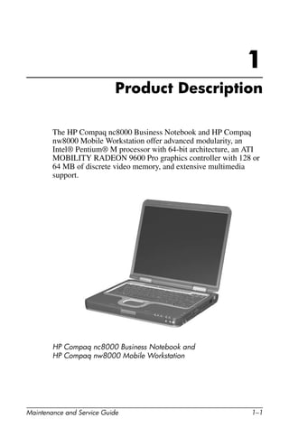
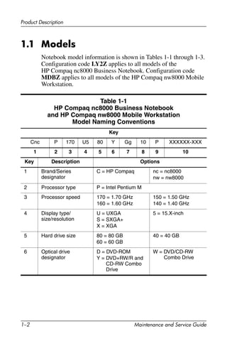
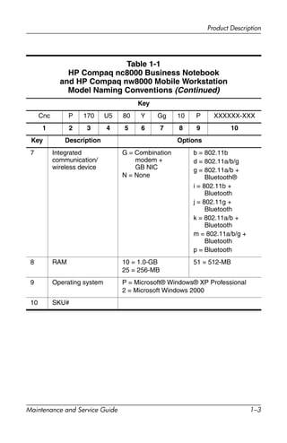
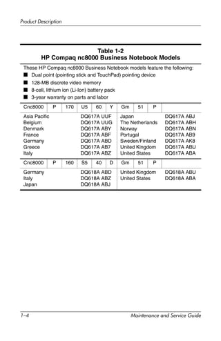
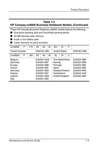
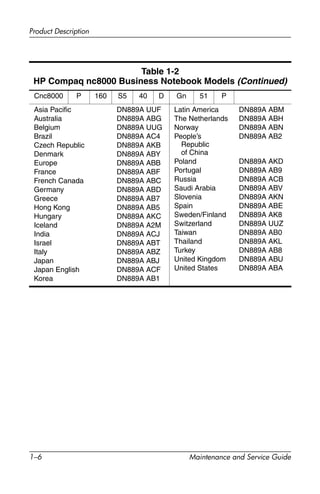
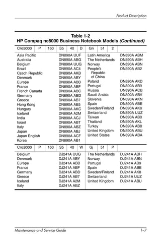
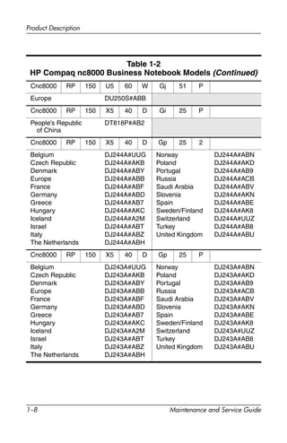
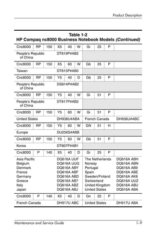
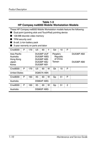
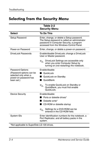
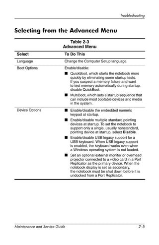
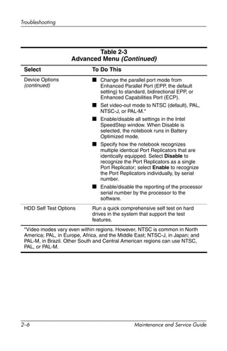
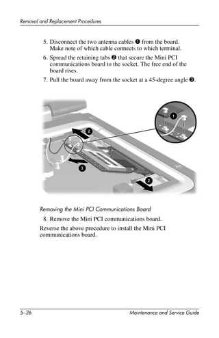
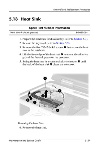
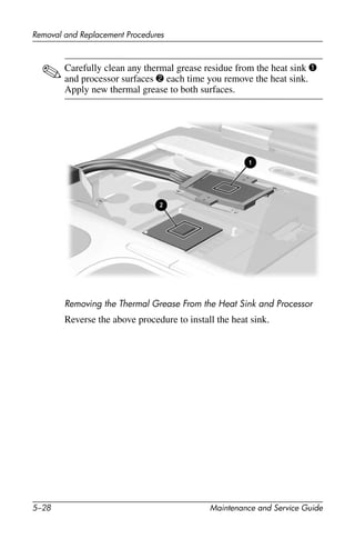
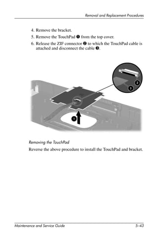
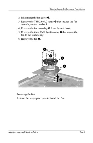
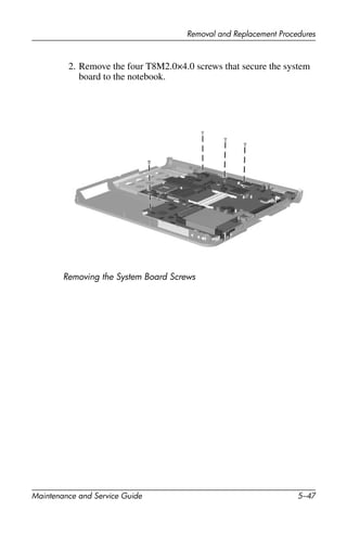
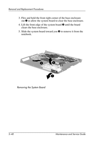
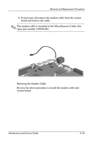
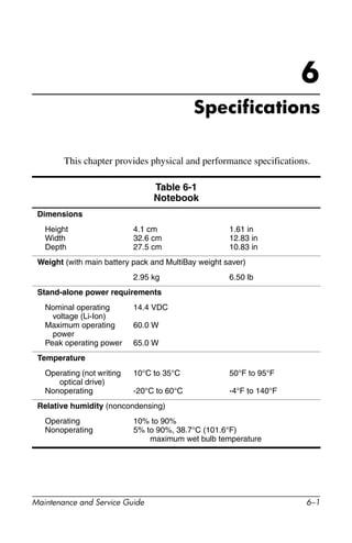
Maintenance and Service
Guide
HP Compaq nc8000 Business Notebook
HP Compaq nw8000 Mobile Workstation
Document Part Number: 333954-005
October 2006
This guide is a troubleshooting reference used for maintaining
and servicing the notebook. It provides comprehensive
information on identifying notebook features, components, and
spare parts; troubleshooting notebook problems; and performing
notebook disassembly procedures.
© Copyright 2003, 2004, 2006 Hewlett-Packard Development Company,
L.P.
Microsoft and Windows are U.S. registered trademarks of Microsoft
Corporation. Intel and Pentium are trademarks or registered trademarks of
Intel Corporation or its subsidiaries in the United States and other
countries. SD Logo is a trademark of its proprietor. Bluetooth is a
trademark owned by its proprietor and used by Hewlett-Packard Company
under license.
The information contained herein is subject to change without notice. The
only warranties for HP products and services are set forth in the express
warranty statements accompanying such products and services. Nothing
herein should be construed as constituting an additional warranty. HP shall
not be liable for technical or editorial errors or omissions contained herein.
Maintenance and Service Guide
HP Compaq nc8000 Business Notebook
HP Compaq nw8000 Mobile Workstation
Fifth Edition: October 2006
First Edition: September 2003
Document Part Number: 333954-005
Maintenance and Service Guide iii
Contents
1 Product Description
1.1 Models. . . . . . . . . . . . . . . . . . . . . . . . . . . . . . . . . . . . 1–2
1.2 Features . . . . . . . . . . . . . . . . . . . . . . . . . . . . . . . . . . 1–13
1.3 Clearing a Password . . . . . . . . . . . . . . . . . . . . . . . . 1–16
1.4 Power Management. . . . . . . . . . . . . . . . . . . . . . . . . 1–17
1.5 External Components . . . . . . . . . . . . . . . . . . . . . . . 1–18
1.6 Design Overview. . . . . . . . . . . . . . . . . . . . . . . . . . . 1–31
2 Troubleshooting
2.1 Computer Setup and Diagnostics Utilities . . . . . . . . 2–2
2.2 Using Diagnostics for Windows . . . . . . . . . . . . . . . . 2–7
2.3 Troubleshooting Flowcharts . . . . . . . . . . . . . . . . . . 2–10
iv Maintenance and Service Guide
Contents
3 Illustrated Parts Catalog
3.1 Serial Number Location . . . . . . . . . . . . . . . . . . . . . . 3–1
3.2 Notebook Major Components. . . . . . . . . . . . . . . . . . 3–2
3.3 Miscellaneous Plastics Kit Components. . . . . . . . . . 3–9
3.4 Miscellaneous Cable Kit Components . . . . . . . . . . 3–10
3.5 Mass Storage Devices . . . . . . . . . . . . . . . . . . . . . . . 3–11
3.6 Miscellaneous . . . . . . . . . . . . . . . . . . . . . . . . . . . . . 3–13
3.7 Sequential Part Number Listing . . . . . . . . . . . . . . . 3–14
4 Removal and Replacement Preliminaries
4.1 Tools Required . . . . . . . . . . . . . . . . . . . . . . . . . . . . . 4–1
4.2 Service Considerations . . . . . . . . . . . . . . . . . . . . . . . 4–2
4.3 Preventing Damage to Removable Drives . . . . . . . . 4–3
4.4 Preventing Electrostatic Damage . . . . . . . . . . . . . . . 4–4
4.5 Packaging and Transporting Precautions . . . . . . . . . 4–5
4.6 Workstation Precautions . . . . . . . . . . . . . . . . . . . . . . 4–6
4.7 Grounding Equipment and Methods. . . . . . . . . . . . . 4–7
Contents
Maintenance and Service Guide v
5 Removal and Replacement Procedures
5.1 Serial Number . . . . . . . . . . . . . . . . . . . . . . . . . . . . . . 5–2
5.2 Disassembly Sequence Chart . . . . . . . . . . . . . . . . . . 5–3
5.3 Preparing the Notebook for Disassembly . . . . . . . . . 5–5
5.4 Notebook Feet. . . . . . . . . . . . . . . . . . . . . . . . . . . . . 5–11
5.5 MultiBay Device. . . . . . . . . . . . . . . . . . . . . . . . . . . 5–12
5.6 Bluetooth Board . . . . . . . . . . . . . . . . . . . . . . . . . . . 5–13
5.7 Integrated Smart Card . . . . . . . . . . . . . . . . . . . . . . . 5–15
5.8 Optical Drive. . . . . . . . . . . . . . . . . . . . . . . . . . . . . . 5–17
5.9 Keyboard. . . . . . . . . . . . . . . . . . . . . . . . . . . . . . . . . 5–18
5.10 Memory Expansion Board . . . . . . . . . . . . . . . . . . 5–22
5.11 Modem Board . . . . . . . . . . . . . . . . . . . . . . . . . . . . 5–23
5.12 Mini PCI Communications Board. . . . . . . . . . . . . 5–24
5.13 Heat Sink. . . . . . . . . . . . . . . . . . . . . . . . . . . . . . . . 5–27
5.14 Processor . . . . . . . . . . . . . . . . . . . . . . . . . . . . . . . . 5–29
5.15 LED Switch Cover . . . . . . . . . . . . . . . . . . . . . . . . 5–31
5.16 RTC Battery . . . . . . . . . . . . . . . . . . . . . . . . . . . . . 5–33
5.17 Security Module (TPM) . . . . . . . . . . . . . . . . . . . . 5–34
5.18 Display Assembly . . . . . . . . . . . . . . . . . . . . . . . . . 5–35
5.19 Top Cover . . . . . . . . . . . . . . . . . . . . . . . . . . . . . . . 5–38
5.20 Speaker . . . . . . . . . . . . . . . . . . . . . . . . . . . . . . . . . 5–41
5.21 TouchPad. . . . . . . . . . . . . . . . . . . . . . . . . . . . . . . . 5–42
5.22 Fan Assembly . . . . . . . . . . . . . . . . . . . . . . . . . . . . 5–44
5.23 System Board . . . . . . . . . . . . . . . . . . . . . . . . . . . . 5–46
vi Maintenance and Service Guide
Contents
6 Specifications
A Connector Pin Assignments
B Power Cord Requirements
C Screw Listing
Index
Maintenance and Service Guide 1–1
1
Product Description
The HP Compaq nc8000 Business Notebook and HP Compaq
nw8000 Mobile Workstation offer advanced modularity, an
Intel® Pentium® M processor with 64-bit architecture, an ATI
MOBILITY RADEON 9600 Pro graphics controller with 128 or
64 MB of discrete video memory, and extensive multimedia
support.
HP Compaq nc8000 Business Notebook and
HP Compaq nw8000 Mobile Workstation
1–2 Maintenance and Service Guide
Product Description
1.1 Models
Notebook model information is shown in Tables 1-1 through 1-3.
Configuration code LY2Z applies to all models of the
HP Compaq nc8000 Business Notebook. Configuration code
MDBZ applies to all models of the HP Compaq nw8000 Mobile
Workstation.
Table 1-1
HP Compaq nc8000 Business Notebook
and HP Compaq nw8000 Mobile Workstation
Model Naming Conventions
Key
Cnc P 170 U5 80 Y Gg 10 P XXXXXX-XXX
1 2 3 4 5 6 7 8 9 10
Key Description Options
1 Brand/Series
designator
C = HP Compaq nc = nc8000
nw = nw8000
2 Processor type P = Intel Pentium M
3 Processor speed 170 = 1.70 GHz
160 = 1.60 GHz
150 = 1.50 GHz
140 = 1.40 GHz
4 Display type/
size/resolution
U = UXGA
S = SXGA+
X = XGA
5 = 15.X-inch
5 Hard drive size 80 = 80 GB
60 = 60 GB
40 = 40 GB
6 Optical drive
designator
D = DVD-ROM
Y = DVD+RW/R and
CD-RW Combo
Drive
W = DVD/CD-RW
Combo Drive
Product Description
Maintenance and Service Guide 1–3
Key
Cnc P 170 U5 80 Y Gg 10 P XXXXXX-XXX
1 2 3 4 5 6 7 8 9 10
Key Description Options
7 Integrated
communication/
wireless device
G = Combination
modem +
GB NIC
N = None
b = 802.11b
d = 802.11a/b/g
g = 802.11a/b +
Bluetooth®
i = 802.11b +
Bluetooth
j = 802.11g +
Bluetooth
k = 802.11a/b +
Bluetooth
m = 802.11a/b/g +
Bluetooth
p = Bluetooth
8 RAM 10 = 1.0-GB
25 = 256-MB
51 = 512-MB
9 Operating system P = Microsoft® Windows® XP Professional
2 = Microsoft Windows 2000
10 SKU#
Table 1-1
HP Compaq nc8000 Business Notebook
and HP Compaq nw8000 Mobile Workstation
Model Naming Conventions (Continued)
1–4 Maintenance and Service Guide
Product Description
Table 1-2
HP Compaq nc8000 Business Notebook Models
These HP Compaq nc8000 Business Notebook models feature the following:
■ Dual point (pointing stick and TouchPad) pointing device
■ 128-MB discrete video memory
■ 8-cell, lithium ion (Li-Ion) battery pack
■ 3-year warranty on parts and labor
Cnc8000 P 170 U5 60 Y Gm 51 P
Asia Pacific
Belgium
Denmark
France
Germany
Greece
Italy
DQ617A UUF
DQ617A UUG
DQ617A ABY
DQ617A ABF
DQ617A ABD
DQ617A AB7
DQ617A ABZ
Japan
The Netherlands
Norway
Portugal
Sweden/Finland
United Kingdom
United States
DQ617A ABJ
DQ617A ABH
DQ617A ABN
DQ617A AB9
DQ617A AK8
DQ617A ABU
DQ617A ABA
Cnc8000 P 160 S5 40 D Gm 51 P
Germany
Italy
Japan
DQ618A ABD
DQ618A ABZ
DQ618A ABJ
United Kingdom
United States
DQ618A ABU
DQ618A ABA
Product Description
Maintenance and Service Guide 1–5
These HP Compaq Business Notebook nc8000 models feature the following:
■ Dual point (pointing stick and TouchPad) pointing device
■ 64-MB discrete video memory
■ 8-cell, Li-Ion battery pack
■ 3-year warranty on parts and labor
Cnc8000 P 170 X5 60 W Gm 51 P
French Canada DH918U ABC United States DH918U ABA
Cnc8000 P 160 S5 40 W Gj 51 2
Belgium
Denmark
Europe
France
Germany
Greece
Iceland
Italy
DJ242A UUG
DJ242A ABY
DJ242A ABB
DJ242A ABF
DJ242A ABD
DJ242A AB7
DJ242A A2M
DJ242A ABZ
The Netherlands
Norway
Portugal
Spain
Sweden/Finland
Switzerland
United Kingdom
DJ242A ABH
DJ242A ABN
DJ242A AB9
DJ242A ABE
DJ242A AK8
DJ242A UUZ
DJ242A ABU
Table 1-2
HP Compaq nc8000 Business Notebook Models (Continued)
1–6 Maintenance and Service Guide
Product Description
Cnc8000 P 160 S5 40 D Gn 51 P
Asia Pacific
Australia
Belgium
Brazil
Czech Republic
Denmark
Europe
France
French Canada
Germany
Greece
Hong Kong
Hungary
Iceland
India
Israel
Italy
Japan
Japan English
Korea
DN889A UUF
DN889A ABG
DN889A UUG
DN889A AC4
DN889A AKB
DN889A ABY
DN889A ABB
DN889A ABF
DN889A ABC
DN889A ABD
DN889A AB7
DN889A AB5
DN889A AKC
DN889A A2M
DN889A ACJ
DN889A ABT
DN889A ABZ
DN889A ABJ
DN889A ACF
DN889A AB1
Latin America
The Netherlands
Norway
People’s
Republic
of China
Poland
Portugal
Russia
Saudi Arabia
Slovenia
Spain
Sweden/Finland
Switzerland
Taiwan
Thailand
Turkey
United Kingdom
United States
DN889A ABM
DN889A ABH
DN889A ABN
DN889A AB2
DN889A AKD
DN889A AB9
DN889A ACB
DN889A ABV
DN889A AKN
DN889A ABE
DN889A AK8
DN889A UUZ
DN889A AB0
DN889A AKL
DN889A AB8
DN889A ABU
DN889A ABA
Table 1-2
HP Compaq nc8000 Business Notebook Models (Continued)
Product Description
Maintenance and Service Guide 1–7
Cnc8000 P 160 S5 40 D Gn 51 2
Asia Pacific
Australia
Belgium
Brazil
Czech Republic
Denmark
Europe
France
French Canada
Germany
Greece
Hong Kong
Hungary
Iceland
India
Israel
Italy
Japan
Japan English
Korea
DN890A UUF
DN890A ABG
DN890A UUG
DN890A AC4
DN890A AKB
DN890A ABY
DN890A ABB
DN890A ABF
DN890A ABC
DN890A ABD
DN890A AB7
DN890A AB5
DN890A AKC
DN890A A2M
DN890A ACJ
DN890A ABT
DN890A ABZ
DN890A ABJ
DN890A ACF
DN890A AB1
Latin America
The Netherlands
Norway
People’s
Republic
of China
Poland
Portugal
Russia
Saudi Arabia
Slovenia
Spain
Sweden/Finland
Switzerland
Taiwan
Thailand
Turkey
United Kingdom
United States
DN890A ABM
DN890A ABH
DN890A ABN
DN890A AB2
DN890A AKD
DN890A AB9
DN890A ACB
DN890A ABV
DN890A AKN
DN890A ABE
DN890A AK8
DN890A UUZ
DN890A AB0
DN890A AKL
DN890A AB8
DN890A ABU
DN890A ABA
Cnc8000 P 160 S5 40 W Gj 51 P
Belgium
Denmark
Europe
France
Germany
Greece
Iceland
Italy
DJ241A UUG
DJ241A ABY
DJ241A ABB
DJ241A ABF
DJ241A ABD
DJ241A AB7
DJ241A A2M
DJ241A ABZ
The Netherlands
Norway
Portugal
Spain
Sweden/Finland
Switzerland
United Kingdom
DJ241A ABH
DJ241A ABN
DJ241A AB9
DJ241A ABE
DJ241A AK8
DJ241A UUZ
DJ241A ABU
Table 1-2
HP Compaq nc8000 Business Notebook Models (Continued)
1–8 Maintenance and Service Guide
Product Description
Cnc8000 RP 150 U5 60 W Gj 51 P
Europe DU250S#ABB
Cnc8000 RP 150 X5 40 D Gi 25 P
People’s Republic
of China
DT818P#AB2
Cnc8000 RP 150 X5 40 D Gp 25 2
Belgium
Czech Republic
Denmark
Europe
France
Germany
Greece
Hungary
Iceland
Israel
Italy
The Netherlands
DJ244A#UUG
DJ244A#AKB
DJ244A#ABY
DJ244A#ABB
DJ244A#ABF
DJ244A#ABD
DJ244A#AB7
DJ244A#AKC
DJ244A#A2M
DJ244A#ABT
DJ244A#ABZ
DJ244A#ABH
Norway
Poland
Portugal
Russia
Saudi Arabia
Slovenia
Spain
Sweden/Finland
Switzerland
Turkey
United Kingdom
DJ244A#ABN
DJ244A#AKD
DJ244A#AB9
DJ244A#ACB
DJ244A#ABV
DJ244A#AKN
DJ244A#ABE
DJ244A#AK8
DJ244A#UUZ
DJ244A#AB8
DJ244A#ABU
Cnc8000 RP 150 X5 40 D Gp 25 P
Belgium
Czech Republic
Denmark
Europe
France
Germany
Greece
Hungary
Iceland
Israel
Italy
The Netherlands
DJ243A#UUG
DJ243A#AKB
DJ243A#ABY
DJ243A#ABB
DJ243A#ABF
DJ243A#ABD
DJ243A#AB7
DJ243A#AKC
DJ243A#A2M
DJ243A#ABT
DJ243A#ABZ
DJ243A#ABH
Norway
Poland
Portugal
Russia
Saudi Arabia
Slovenia
Spain
Sweden/Finland
Switzerland
Turkey
United Kingdom
DJ243A#ABN
DJ243A#AKD
DJ243A#AB9
DJ243A#ACB
DJ243A#ABV
DJ243A#AKN
DJ243A#ABE
DJ243A#AK8
DJ243A#UUZ
DJ243A#AB8
DJ243A#ABU
Table 1-2
HP Compaq nc8000 Business Notebook Models (Continued)
Product Description
Maintenance and Service Guide 1–9
Cnc8000 RP 150 X5 40 W Gi 25 P
People’s Republic
of China
DT819P#AB2
Cnc8000 RP 150 X5 60 W Gb 25 P
Taiwan DT815P#AB0
Cnc8000 RP 150 Y5 40 D Gb 25 P
People’s Republic
of China
DS814P#AB2
Cnc8000 RP 150 Y5 40 W Gi 51 P
People’s Republic
of China
DT817P#AB2
Cnc8000 RP 150 Y5 60 W Gi 51 P
United States DH936U#ABA French Canada DH936U#ABC
Cnc8000 RP 150 Y5 60 W GN 51 H
Europe DU256S#ABB
Cnc8000 RP 150 Y5 60 W Gb 51 P
Korea DT807P#AB1
Cnc8000 P 140 X5 40 D Gi 25 P
Asia Pacific
Belgium
Denmark
France
Germany
Greece
Italy
Japan
DQ616A UUF
DQ616A UUG
DQ616A ABY
DQ616A ABF
DQ616A ABD
DQ616A AB7
DQ616A ABZ
DQ616A ABJ
The Netherlands
Norway
Portugal
Spain
Sweden/Finland
Switzerland
United Kingdom
United States
DQ616A ABH
DQ616A ABN
DQ616A AB9
DQ616A ABE
DQ616A AK8
DQ616A UUZ
DQ616A ABU
DQ616A ABA
Cnc8000 P 140 X5 40 D Gn 25 P
French Canada DH917U ABC United States DH917U ABA
Table 1-2
HP Compaq nc8000 Business Notebook Models (Continued)
1–10 Maintenance and Service Guide
Product Description
Table 1-3
HP Compaq nw8000 Mobile Workstation Models
These HP Compaq nw8000 Mobile Workstation models feature the following:
■ Dual point (pointing stick and TouchPad) pointing device
■ 128-MB discrete video memory
■ TPM security card
■ 8-cell, Li-Ion battery pack
■ 3-year warranty on parts and labor
Cnw8000 P 170 U5 60 Y Gd 10 P
Asia Pacific
Australia
Hong Kong
Japan
Korea
DU536P UUF
DU536P ABG
DU536P AB5
DU536P ABJ
DU536P AB1
People’s
Republic
of China
Taiwan
DU536P AB2
DU536P AB0
Cnw8000 P 170 U5 60 W Gk 10 P
United States DQ857A ABA
Cnw8000 P 160 X5 60 W Gp 51 P
Australia DS864P ABG
Cnw8000 P 160 X5 60 W Gp 51 2
Australia DS865P ABG
Product Description
Maintenance and Service Guide 1–11
These HP Compaq nw8000 Mobile Workstation models feature the following:
■ Dual point (pointing stick and TouchPad) pointing device
■ 128-MB discrete video memory
■ 8-cell, Li-Ion battery pack
■ 3-year warranty on parts and labor
Cnw8000 P 170 U5 60 Y Gd 10 P
Australia
Hong Kong
Japan
Korea
DU535P ABG
DU535P AB5
DU535P ABJ
DU535P AB1
People’s
Republic
of China
Taiwan
DU535P AB2
DU535P AB0
Cnw8000 P 170 U5 60 Y Gn 51 P
Asia Pacific
Australia
Belgium
Europe
France
French Canada
Germany
Italy
Japan
Korea
Hong Kong
DN912A UUF
DN912A ABG
DN912A UUG
DN912A ABB
DN912A ABF
DN912A ABC
DN912A ABD
DN912A ABZ
DN912A ABJ
DN912A AB1
DN912A AB5
Latin America
People’s
Republic
of China
Spain
Sweden/Finland
Switzerland
Taiwan
United Kingdom
United States
DN912A ABM
DN912A AB2
DN912A ABE
DN912A AK8
DN912A UUZ
DN912A AB0
DN912A ABU
DN912A ABA
Cnw8000 P 170 U5 60 Y Gn 51 2
Asia Pacific
Australia
Belgium
Europe
France
French Canada
Germany
Italy
Japan
Korea
Hong Kong
DN913A UUF
DN913A ABG
DN913A UUG
DN913A ABB
DN913A ABF
DN913A ABC
DN913A ABD
DN913A ABZ
DN913A ABJ
DN913A AB1
DN913A AB5
Latin America
People’s
Republic
of China
Spain
Sweden/Finland
Switzerland
Taiwan
United Kingdom
United States
DN913A ABM
DN913A AB2
DN913A ABE
DN913A AK8
DN913A UUZ
DN913A AB0
DN913A ABU
DN913A ABA
Table 1-3
HP Compaq nw8000 Mobile Workstation Models (Continued)
1–12 Maintenance and Service Guide
Product Description
Cnw8000 P 170 U5 60 W Gm 51 P
Asia Pacific DU534P UUF
Cnw8000 P 170 U5 60 W Gd 10 P
Asia Pacific DU535P UUF Japan DU529P ABJ
Cnw8000 P 170 U5 60 W Gd 10 2
Japan DU530P ABJ
Cnw8000 P 170 U5 60 W Gd 51 P
Japan DU531P ABJ
Cnw8000 P 170 S5 60 W Gk 51 P
Europe
France
Germany
Italy
DQ556A ABB
DQ556A ABF
DQ556A ABD
DQ556A ABZ
Japan
United Kingdom
United States
DQ556A ABJ
DQ556A ABU
DQ556A ABA
Cnw8000 P 170 X5 60 W Gm 51 P
Asia Pacific DU532P UUF
Cnw8000 P 160 X5 60 W Gi 51 P
People’s Republic
of China
DT821P AB2
Cnw8000 P 150 X5 60 W Gm 51 P
Asia Pacific DU533P UUF
Cnw8000 P 150 X5 60 W Gi 51 P
People’s Republic
of China
DT820P AB2
Cnw8000 P 170 U5 60 W Gm 10 P
French Canada DH919U ABC United States DH919U ABA
Table 1-3
HP Compaq nw8000 Mobile Workstation Models (Continued)
Product Description
Maintenance and Service Guide 1–13
1.2 Features
■ Intel Pentium M 1.7-, 1.6-, 1.5-, and 1.4-GHz processors,
all with 1024-KB L2 cache and 400-MHz processor side bus,
varying by notebook model
■ 15.1-inch UXGA (1600×1200), SXGA+ (1400×1050), or
XGA (1024×768) TFT display with over 16.7 million colors,
varying by notebook model
■ ATI MOBILITY RADEON 9600 Pro graphics controller
with 128 or 64 MB of video memory, varying by notebook
model
■ 80-, 60-, or 40-GB high-capacity hard drive, varying by
notebook model
■ 256-MB DDR Synchronous DRAM (SDRAM) at 333 MHz,
expandable to 2.0 GB
■ Microsoft® Windows® 2000 or Windows XP Professional,
varying by notebook model
■ Full-size Windows 98 keyboard with integrated numeric
keypad
■ Dual point (TouchPad and pointing stick) pointing device,
with TouchPad on/off button and light
Cnw8000 P 170 U5 60 W Gg 51 P
Belgium
Europe
France
Germany
Italy
DJ294A UUG
DJ294A ABB
DJ294A ABF
DJ294A ABD
DJ294A ABZ
Spain
Sweden
Switzerland
United Kingdom
DJ294A ABE
DJ294A AK8
DJ294A UUZ
DJ294A ABU
Cnw8000 P 160 S5 40 W Gn 51 P
French Canada DH920U ABC United States DH920U ABA
Table 1-3
HP Compaq nw8000 Mobile Workstation Models (Continued)
1–14 Maintenance and Service Guide
Product Description
■ Integrated Secure Digital (SD) Memory Card flash media slot
■ Integrated 10/100/1000 BASE-T Ethernet local area network
(LAN) NIC with RJ-45 connector
■ Integrated wireless support for Bluetooth® LAN and Mini
PCI 802.11a/b/g LAN devices
■ Support for fixed optical drive and MultiBay device
■ Support for two Type II/Type III PC Card slots (one
integrated) with support for both 32-bit (CardBus) and 16-bit
PC Cards
■ External 65-W AC adapter with power cord
■ 8-cell Li-Ion battery pack
■ HP PremierSound audio
■ Support for the following optical drives:
❏ 24X Max DVD/CD-RW Combo Drive
❏ 24X Max DVD+RW/R and CD-RW Combo Drive
❏ 8X Max DVD-ROM Drive
❏ 24X Max CD-ROM Drive
Product Description
Maintenance and Service Guide 1–15
■ Connectors:
❏ SD Card
❏ Infrared
❏ Two Type II PC Card slots
❏ RJ-11 (modem)
❏ RJ-45 (NIC)
❏ Two Universal Serial Bus (USB) 2.0
❏ S-Video
❏ Parallel
❏ Serial
❏ External monitor
❏ DC power
❏ Docking
❏ IEEE 1394 digital
❏ Microphone
❏ Stereo speaker/headphone
1–16 Maintenance and Service Guide
Product Description
1.3 Clearing a Password
If the notebook you are servicing has an unknown password,
follow these steps to clear the password. These steps also
clear the CMOS memory:
1. Prepare the notebook for disassembly (refer to Section
“5.3 Preparing the Notebook for Disassembly” for more
information).
2. Remove the real time clock (RTC) battery (refer to Section
“5.16 RTC Battery”).
3. Wait approximately 5 minutes.
4. Replace the RTC battery and reassemble the notebook.
5. Connect AC power to the notebook. Do not reinsert any
battery packs at this time.
6. Turn on the notebook.
All passwords and all CMOS settings are cleared.
Product Description
Maintenance and Service Guide 1–17
1.4 Power Management
The notebook comes with power management features that
extend battery operating time and conserve power. The notebook
supports the following power management features:
■ Standby
■ Hibernation
■ Setting customization by the user
■ Hotkeys for setting the level of performance
■ Lid switch standby/resume
■ Power/standby button
■ Advanced Configuration and Power Management (ACPM)
compliance
1–18 Maintenance and Service Guide
Product Description
1.5 External Components
The external components on the front and right side of the
notebook are shown below and described in Table 1-4.
Front and Right-Side Components
Product Description
Maintenance and Service Guide 1–19
Table 1-4
Front and Right-Side Components
Item Component Function
1 Stereo speakers (2) Produce stereo sound.
2 Display release latch Opens the notebook.
3 Mute button Mutes the system volume. The button lights
up when volume is muted.
4 Volume control
buttons
Increase and decrease system volume.
Press the volume up button (on right) to
increase sound. Press the volume down
button (on left) to decrease sound.
5 PC Card eject buttons Eject an optional PC Card or smart card
(if a smart card reader is installed) from the
top or bottom PC Card slot.
6 Audio line-out jack Connects optional powered stereo
speakers, headphones, headset, or
television audio.
7 Microphone jack Connects an optional monaural
microphone.
8 PC Card slots Support optional Type I, Type II, or Type III
32-bit (CardBus) or 16-bit PC Cards.
✎ In select notebooks, one PC Card
slot can be replaced with a
factory-installed smart card
reader.
9 Secure Digital (SD)
slot
Accepts SD Memory Card and
MultiMedia Cards.
10 MultiBay Supports an optional MultiBay device, such
as a drive or battery pack.
11 Infrared port Provides wireless communication between
the notebook and an optional
IrDA-compliant device.
12 RJ-11 jack Connects a modem cable.
1–20 Maintenance and Service Guide
Product Description
The external components on the rear and left side are shown
below and described in Table 1-5.
Rear and Left-Side Components
Product Description
Maintenance and Service Guide 1–21
Table 1-5
Rear and Left-Side Components
Item Component Function
1 USB connectors (2) Connect USB 1.1- and 2.0-compliant
devices to the notebook using a standard
USB cable.
The bottom connector is a self-powered
USB connector. It can be used to connect
USB 1.1- and 2.0-compliant devices to the
notebook using a standard USB cable,
and connect an optional External MultiBay
to the notebook using the External
MultiBay-powered USB cable.
2 1394 connector Connects a device that requires high
bandwidth, such as a digital camera or
other video or audio device.
1–22 Maintenance and Service Guide
Product Description
3 Power connector Connects an AC adapter or an optional
Automobile Power Adapter/Charger or
Aircraft Power Adapter.
4 Serial connector Connects an optional serial device.
5 Parallel connector Connects an optional parallel device, such
as an external diskette drive or a printer.
6 S-Video out jack Connects an optional S-Video device, such
as a television, VCR, camcorder, overhead
projector, or video capture card.
7 External monitor
connector
Connects an optional external monitor or
overhead projector.
8 RJ-45 jack Connects a network cable.
9 Intake vents (2) Enable airflow to cool internal components.
Ä To prevent overheating, do not
obstruct vents. Using the notebook
on a soft surface, such as a pillow,
blanket, rug, or thick clothing, can
block airflow.
10 Security cable slot Attaches an optional security cable to the
notebook.
✎ The purpose of security solutions
is to act as a deterrent. These
solutions do not prevent the
product from being mishandled or
stolen.
11 Optical disk drive Reads and records CD and DVD media.
12 Battery bay Holds the primary battery pack. The battery
pack ships outside the notebook.
Table 1-5
Rear and Left-Side Components (Continued)
Item Component Function
Product Description
Maintenance and Service Guide 1–23
The notebook keyboard components are shown below and
described in Table 1-6.
Keyboard Components
1–24 Maintenance and Service Guide
Product Description
Table 1-6
Keyboard Components
Item Component Function
1 Windows logo key Displays the Windows Start menu.
2 fn key Executes frequently used system functions
when pressed in combination with a
function key or the esc key.
3 caps lock key Enables capital alphabetic character lock.
4 f1 through f12 function
keys
Execute indicated system functions when
pressed in combination with the fn key.
5 num lock key Enables numeric lock and the internal
keypad.
6 Internal keypad Can be used like the keys on an external
numeric keypad.
7 Cursor control keys Move the cursor around the screen.
8 Application key Displays shortcut menu for items beneath
the pointer.
Product Description
Maintenance and Service Guide 1–25
The notebook top components are shown below and described in
Table 1-7.
Top Components
1–26 Maintenance and Service Guide
Product Description
Table 1-7
Top Components
Item Component Function
1 Intake vents (2) Enable airflow to cool internal components.
Ä To prevent overheating, do not
obstruct vents. Using the notebook
on a soft surface, such as a pillow,
blanket, rug, or thick clothing, can
block airflow.
2 Power button When the notebook is:
■ Off, press and release to turn on the
notebook.
■ In Standby, press and release to exit
Standby.
■ In Hibernation, press and release to exit
Hibernation.
If the system has stopped responding and
Windows shutdown procedures cannot be
used, press and hold for five seconds to
turn off the notebook.
3 Quick Launch
buttons (3)
Enable you to access common functions
with a single keystroke.
4 Num lock light On: Num lock is on or the embedded
numeric keypad is enabled.
5 Caps lock light On: Caps lock is on.
6 Scroll lock light On: Scroll lock is on.
7 Display lid switch ■ If the notebook is closed while on, turns
off the display.
■ If the notebook is opened while in
Standby, turns on the notebook
(resumes from Standby).
8 Pointing stick Moves the pointer and selects or activates
items on the screen.
9 Microphone Allows for audio input.
Product Description
Maintenance and Service Guide 1–27
Top Components (Continued)
1–28 Maintenance and Service Guide
Product Description
Table 1-7
Top Components (Continued)
Item Component Function
10 MultiBay light On: A drive in the MultiBay is being
accessed.
11 Drive light On: One of the following integrated drives is
being accessed:
■ Hard drive
■ Fixed optical drive
12 Battery light On: A battery pack is charging.
Blinking: A battery pack that is the only
available power source has reached a
low-battery condition. When the battery
reaches a critical low-battery condition, the
battery light begins blinking more quickly.
13 Power/Standby light On: Power is turned on.
Blinking: Notebook is in standby.
✎ The power/standby light also
blinks when a battery pack that is
the only available power source
reaches a critical low-battery
condition. The light turns off when
the system enters hibernation or
shuts down.
14 Wireless on/off light On: An integrated wireless device has been
enabled.
15 Left and right
TouchPad buttons
Function like the left and right buttons on an
external mouse.
16 TouchPad Moves the pointer and selects or activates
items on the screen. Can be set to perform
other mouse functions, such as scrolling
and double-clicking.
17 Left and right pointing
stick buttons
Function like the left and right buttons on an
external mouse.
Product Description
Maintenance and Service Guide 1–29
The external components on the bottom of the notebook are
shown below and described in Table 1-8.
Bottom Components
1–30 Maintenance and Service Guide
Product Description
Table 1-8
Bottom Components
Item Component Function
1 MultiBay Supports an optional MultiBay
device, such as a drive or battery
pack.
2 MultiBay release latch Allows removal of the MultiBay
drive.
3 Bluetooth compartment Holds a Bluetooth device.
✎ Bluetooth is not available
in all countries.
4 Docking connector Connects the notebook to an
optional port replicator.
5 Optical disk drive Reads and records CD and DVD
media.
6 Serial number Identifies the notebook.
You need this number when calling
customer support.
7 Battery pack release latch Releases the primary battery pack
from the battery bay.
8 Battery bay Holds the primary battery pack.
Battery pack ships outside the
notebook.
9 Hard drive cover latch Releases the cover on the hard
drive bay.
10 Hard drive Holds the primary hard drive.
Product Description
Maintenance and Service Guide 1–31
1.6 Design Overview
This section presents a design overview of key parts and features
of the notebook. Refer to Chapter 3, “Illustrated Parts Catalog”
to identify replacement parts, and Chapter 5, “Removal and
Replacement Procedures” for disassembly steps.
The system board provides the following device connections:
■ Memory expansion board
■ Mini PCI communications devices
■ Hard drive
■ Display
■ Keyboard, TouchPad, and pointing stick
■ Audio
■ Intel Pentium M processor
■ Fan
■ PC Card
■ MCD modem
■ Bluetooth wireless LAN
ÄCAUTION: To properly ventilate the notebook, allow at least a 7.6-cm
(3-inch) clearance on the left and right sides of the notebook.
The notebook uses an electrical fan for ventilation. The fan is
controlled by a temperature sensor and is designed to turn on
automatically when high temperature conditions exist. These
conditions are affected by high external temperatures, system
power consumption, power management/battery conservation
configurations, battery fast charging, and software applications.
Exhaust air is displaced through the ventilation grill located on
the left side of the notebook.
Maintenance and Service Guide 2–1
2
Troubleshooting
ÅWARNING: Only authorized technicians trained by HP should
repair this equipment. All troubleshooting and repair procedures are
detailed to allow only subassembly/module-level repair. Because of the
complexity of the individual boards and subassemblies, do not attempt
to make repairs at the component level or modifications to any printed
wiring board. Improper repairs can create a safety hazard. Any
indication of component replacement or printed wiring board
modification may void any warranty or exchange allowances.
2–2 Maintenance and Service Guide
Troubleshooting
2.1 Computer Setup and Diagnostics
Utilities
The notebook features two system management utilities:
■ Computer Setup—A system information and customization
utility that can be used even when your operating system is
not working or does not load. This utility includes settings
that are not available in Microsoft Windows.
■ Diagnostics for Windows—A system information and
diagnostic utility that is used within the Windows operating
system. Use this utility whenever possible to:
❏ Display system information.
❏ Test system components.
❏ Troubleshoot a device configuration problem in
Windows XP Professional or Windows XP Home.
✎It is not necessary to configure a device connected to a USB
connector on the notebook or to an optional HP Port Replicator.
Using Computer Setup
Information and settings in Computer Setup are accessed from
the File, Security, or Advanced menus:
1. Turn on or restart the notebook. Press F10 while the
F10 = ROM-Based Setup message is displayed in the lower
left corner of the screen.
❏ To change the language, press F2.
❏ To view navigation information, press F1.
❏ To return to the Computer Setup menu, press esc.
2. Select the File, Security, or Advanced menu.
Troubleshooting
Maintenance and Service Guide 2–3
3. To close Computer Setup and restart the notebook:
❏ Select File > Save Changes and Exit and press enter.
– or –
❏ Select File > Ignore Changes and Exit and press enter.
4. When you are prompted to confirm your action, press F10.
Selecting from the File Menu
Table 2-1
File Menu
Select To Do This
System Information ■ View identification information about the
notebook, a Port Replicator, and any battery
packs in the system.
■ View specification information about the
processor, memory and cache size, and
system ROM.
Save to Floppy Save system configuration settings to a diskette.
Restore from Floppy Restore system configuration settings from
a diskette.
Restore Defaults Replace configuration settings in Computer
Setup with factory default settings. Identification
information is retained.
Ignore Changes and Exit Cancel changes entered during the current
session, then exit and restart the notebook.
Save Changes and Exit Save changes entered during the current
session, then exit and restart the notebook.
2–4 Maintenance and Service Guide
Troubleshooting
Selecting from the Security Menu
Table 2-2
Security Menu
Select To Do This
Setup Password Enter, change, or delete a Setup password.
The Setup password is called an administrator
password in Computer Security, a program
accessed from the Windows Control Panel.
Power-on Password Enter, change, or delete a power-on password.
DriveLock Passwords Enable/disable DriveLock; change a DriveLock
User or Master password.
✎ DriveLock Settings are accessible only
when you enter Computer Setup by
turning on (not restarting) the notebook.
Password Options
(Password options can be
selected only when a
power-on password has
been set.)
Enable/disable:
■ QuickLock
■ QuickLock on Standby
■ QuickBlank
✎ To enable QuickLock on Standby or
QuickBlank, you must first enable
QuickLock.
Device Security Enable/disable:
■ Ports or diskette drives*
■ Diskette write*
■ CD-ROM or diskette startup
✎ Settings for a DVD-ROM can be
entered in the CD-ROM field.
System IDs Enter identification numbers for the notebook, a
Port Replicator, and all battery packs in the
system.
*Not applicable to SuperDisk LS-120 drives.
Troubleshooting
Maintenance and Service Guide 2–5
Selecting from the Advanced Menu
Table 2-3
Advanced Menu
Select To Do This
Language Change the Computer Setup language.
Boot Options Enable/disable:
■ QuickBoot, which starts the notebook more
quickly by eliminating some startup tests.
If you suspect a memory failure and want
to test memory automatically during startup,
disable QuickBoot.
■ MultiBoot, which sets a startup sequence that
can include most bootable devices and media
in the system.
Device Options ■ Enable/disable the embedded numeric
keypad at startup.
■ Enable/disable multiple standard pointing
devices at startup. To set the notebook to
support only a single, usually nonstandard,
pointing device at startup, select Disable.
■ Enable/disable USB legacy support for a
USB keyboard. When USB legacy support
is enabled, the keyboard works even when
a Windows operating system is not loaded.
■ Set an optional external monitor or overhead
projector connected to a video card in a Port
Replicator as the primary device. When the
notebook display is set as secondary,
the notebook must be shut down before it is
undocked from a Port Replicator.
2–6 Maintenance and Service Guide
Troubleshooting
Device Options
(continued)
■ Change the parallel port mode from
Enhanced Parallel Port (EPP, the default
setting) to standard, bidirectional EPP, or
Enhanced Capabilities Port (ECP).
■ Set video-out mode to NTSC (default), PAL,
NTSC-J, or PAL-M.*
■ Enable/disable all settings in the Intel
SpeedStep window. When Disable is
selected, the notebook runs in Battery
Optimized mode.
■ Specify how the notebook recognizes
multiple identical Port Replicators that are
identically equipped. Select Disable to
recognize the Port Replicators as a single
Port Replicator; select Enable to recognize
the Port Replicators individually, by serial
number.
■ Enable/disable the reporting of the processor
serial number by the processor to the
software.
HDD Self Test Options Run a quick comprehensive self test on hard
drives in the system that support the test
features.
*Video modes vary even within regions. However, NTSC is common in North
America; PAL, in Europe, Africa, and the Middle East; NTSC-J, in Japan; and
PAL-M, in Brazil. Other South and Central American regions can use NTSC,
PAL, or PAL-M.
Table 2-3
Advanced Menu (Continued)
Select To Do This
Troubleshooting
Maintenance and Service Guide 2–7
2.2 Using Diagnostics for Windows
When you access Diagnostics for Windows, a scan of all system
components is displayed on the screen before the diagnostics
window opens.
You can display more or less information from anywhere within
Diagnostics for Windows by selecting Level on the menu bar.
Diagnostics for Windows is designed to test HP components. If
HP components are tested, the results might be inconclusive.
Obtaining, Saving, or Printing
Configuration Information
1. Access Diagnostics for Windows by selecting Start >
Settings > Control Panel > Diagnostics for Windows.
2. Select Categories, then select a category from the
drop-down list.
❏ To save the information, select File > Save As.
❏ To print the information, select File > Print.
3. To close Diagnostics for Windows, select File > Exit.
2–8 Maintenance and Service Guide
Troubleshooting
Obtaining, Saving, or Printing Diagnostic
Test Information
1. Access Diagnostics for Windows by selecting Start >
Settings > Control Panel > Diagnostics for Windows.
2. Select the Test tab.
3. In the scroll box, select the category or device you want
to test.
4. Select a test type:
❏ Quick Test—Runs a quick, general test on each device
in a selected category.
❏ Complete Test—Performs maximum testing on each
device in a selected category.
❏ Custom Test—Performs maximum testing on a selected
device.
◆ To run all tests for your selected device, select the
Check All button.
◆ To run only the tests you select, select the
Uncheck All button, then select the check box for
each test you want to run.
5. Select a test mode:
❏ Interactive Mode—Provides maximum control over
the testing process. You determine whether the test was
passed or failed. You might be prompted to insert or
remove devices.
❏ Unattended Mode—Does not display prompts. If errors
are found, they are displayed when testing is complete.
Troubleshooting
Maintenance and Service Guide 2–9
6. Select the Begin Testing button.
7. Select a tab to view a test report:
❏ Status tab—Summarizes the tests run, passed, and failed
during the current testing session.
❏ Log tab—Lists tests run on the system, the number of
times each test has run, the number of errors found on
each test, and the total run time of each test.
❏ Error tab—Lists all errors found in the notebook, along
with the corresponding error codes.
8. Select a tab to save the report:
❏ Log tab—Select the Save button.
❏ Error tab—Select the Save button.
9. Select a tab to print the report:
❏ Log tab—Select File > Save As, and then print the file
from your folder.
2–10 Maintenance and Service Guide
Troubleshooting
2.3 Troubleshooting Flowcharts
Table 2-4
Troubleshooting Flowcharts Overview
Flowchart Description
2.1 “Flowchart 2.1—Initial Troubleshooting”
2.2 “Flowchart 2.2—No Power, Part 1”
2.3 “Flowchart 2.3—No Power, Part 2”
2.4 “Flowchart 2.4—No Power, Part 3”
2.5 “Flowchart 2.5—No Power, Part 4”
2.6 “Flowchart 2.6—No Video, Part 1”
2.7 “Flowchart 2.7—No Video, Part 2”
2.8 “Flowchart 2.8—Nonfunctioning Port Replicator”
2.9 “Flowchart 2.9—No OS Loading”
2.10 “Flowchart 2.10—No OS Loading, Hard Drive, Part 1”
2.11 “Flowchart 2.11—No OS Loading, Hard Drive, Part 2”
2.12 “Flowchart 2.12—No OS Loading, Hard Drive, Part 3”
2.13 “Flowchart 2.13—No OS Loading, Diskette Drive”
2.14 “Flowchart 2.14—No OS Loading, CD- or DVD-ROM Drive”
2.15 “Flowchart 2.15—No Audio, Part 1”
2.16 “Flowchart 2.16—No Audio, Part 2”
2.17 “Flowchart 2.17—Nonfunctioning Device”
2.18 “Flowchart 2.18—Nonfunctioning Keyboard”
2.19 “Flowchart 2.19—Nonfunctioning Pointing Device”
2.20 “Flowchart 2.20—No Network/Modem Connection”
Troubleshooting
Maintenance and Service Guide 2–11
Flowchart 2.1—Initial Troubleshooting
Connecting
to network
or modem?
Begin
troubleshooting.
Is there
power?
Is the OS
loading?
Is there video?
(no boot)
Is there
sound?
Beeps,
LEDs, or error
messages?
Keyboard/
pointing
device
working?
Go to
“Flowchart
2.17—Nonfunc-
tioning Device”
Go to
“Flowchart 2.2—No
Power, Part 1”.
Go to
“Flowchart 2.6—No
Video, Part 1”
All drives
working?
Y
Y
Y
Y
Y
Y
Y
Y
N
N
N
N
N
End
N
N
N
Go to
“Flowchart 2.9—No
OS Loading”
Go to
“Flowchart2.15—No
Audio, Part 1”
Go to
“Flowchart
2.18—Nonfunc-
tioning Key-
board”or
“Flowchart
2.19—Nonfunc-
tioning Pointing
Check
LED board,
speaker
connections.
Go to
“Flowchart2.20—No
Network/Modem
Connection”
2–12 Maintenance and Service Guide
Troubleshooting
Flowchart 2.2—No Power, Part 1
1. Reseat the power cables in the Port Replicator
and at the AC outlet.
2. Ensure that the AC power source is active.
3. Ensure that the power strip is working.
Done
Remove from
Port Replicator
(if applicable).
Power up
on battery
power?
Power up
on AC
power?
Power up in
Port
Replicator?
Power up
on battery
power?
Power up
in Port
Replicator?
Done
*Reset
power.
*Reset
power.
Power up
on AC
power?
N
Y
Y
N
N
Y
N
N
Y
Y
Y N
1. On some models, there is a separate reset
button.
2. On some models, the notebook can be
reset using the Standby switch and either
the lid switch or the main power switch.
*NOTES:
Go to
“Flowchart 2.4—No
Power, Part 3”
Go to
“Flowchart 2.3—No
Power, Part 2”
Go to
“Flowchart
2.8—Nonfunctioning
Port Replicator”
No power
(power LED
is off).
Troubleshooting
Maintenance and Service Guide 2–13
Flowchart 2.3—No Power, Part 2
Continued from
“Flowchart 2.2—No
Power, Part 1”
Visually check for
debris in battery
socket and clean
if necessary.
Done
N
Y
Power on?
Check battery by
recharging it,
moving it to
another notebook,
or replacing it.
Power on?
Done
Y
Replace
power supply
(if applicable).
N
Power on?
Done
Y
N
Go to
“Flowchart 2.4—No
Power, Part 3”
2–14 Maintenance and Service Guide
Troubleshooting
Flowchart 2.4—No Power, Part 3
Continued from
“Flowchart 2.3—No
Power, Part 2”
Reseat AC adapter
in notebook and
at power source.
Internal or
external AC
adapter?
Done
Done
Done
Done
Power on?
Power on?
Power on?
Plug directly
into AC outlet.
Power LED
on?
Power outlet
active?
Try different
outlet.
Replace external
AC adapter.
Replace
power cord.
Y
N
Y
Y
Y
Y
N
N
N
N
External
Internal
Go to
“Flowchart 2.5—No
Power, Part 4”
Troubleshooting
Maintenance and Service Guide 2–15
Flowchart 2.5—No Power, Part 4
Y
N
Continued from
“Flowchart 2.4—No
Power, Part 3”
Reseat loose
components and
boards and
replace damaged
items.
Open
notebook.
Loose or
damaged
parts?
Y
Close
notebook and
retest.
Power on?
Done
N
Replace the following items (if applicable) in the
order given. Check notebook operation after each
of the following two replacement steps:
1. Internal DC to DC converter, processor, and
system board*
2. Internal AC adapter
*NOTE: Replace these items as a set to prevent
shorting out among components.
2–16 Maintenance and Service Guide
Troubleshooting
Flowchart 2.6—No Video, Part 1
A
N
Stand-alone
or Port
Replicator?
No video.
Replace the following one at a time. Test after each replacement.
1. Cable between notebook and notebook display (if applicable)
2. Inverter board (if applicable)
3. Display
4. System board
Internal or
external
display*?
Adjust
brightness. Video OK? Done
Port
Replicator
Internal
Stand-alone
External
Adjust
brightness.
Video OK? Done
Y
Press lid
switch to ensure
operation.
Video OK? Done
Y
N
Video OK?
Done Done
N
Check for bent
pins on cable.
Try
another
display.
Internal and
external
video OK?
Replace
system
board.
Y Y
NN
*NOTE: To change from internal to
external display, use the hotkey
combination.
Y
Go to
“Flowchart 2.7—No
Video, Part 2”
Troubleshooting
Maintenance and Service Guide 2–17
Flowchart 2.7—No Video, Part 2
Y
N
Continued from
“Flowchart 2.6—No
Video, Part 1”
Done
Adjust external
monitor display.
Video OK?
Adjust
display
brightness.
Video OK?
Video OK?
Done
Done
Verify that notebook is properly
seated in Port Replicator, and check for
bent pins on cable and for secure
monitor connection.
Go to “A” in
“Flowchart 2.6—No
Video, Part 1”
Check brightness
of external
monitor.
Try another
external
monitor.
Internal
and external
video OK?
Go to
“Flowchart
2.8—Nonfunctioning
Port Replicator”
Y
Y
Y
N
N
N
Remove
notebook from Port
Replicator,
if connected.
2–18 Maintenance and Service Guide
Troubleshooting
Flowchart 2.8—Nonfunctioning Port Replicator
Y
N
Reseat power
cord in Port
Replicator and
power outlet.
N
Replace the following Port Replicator
components one at a time. Check notebook
operation after each replacement.
1. Power supply
2. I/O board
3. Backplane board
4. Switch box
5. Port Replicator motor mechanism
Check voltage
setting on Port
Replicator.
Reseat monitor
cable connector at
Port Replicator.
Reinstall
notebook into Port
Replicator.
Port
Replicator
operating?
Port
Replicator
operating?
Remove
notebook, reseat
all internal parts,
and replace any
damaged items in
Port Replicator.
Done
Done
Y
Nonfunctioning
Port Replicator.
Troubleshooting
Maintenance and Service Guide 2–19
Flowchart 2.9—No OS Loading
No OS loading from hard drive,
go to “Flowchart 2.10—No OS Loading, Hard Drive,
Part 1”
Reseat power
cord in Port
Replicator and
power outlet.
No OS
loading.*
*NOTE: Before beginning to troubleshoot, always
check cable connections, cable ends, and drives
for bent or damaged pins.
No OS loading from diskette drive,
go to “Flowchart 2.13—No OS Loading, Diskette
Drive”
No OS loading from CD- or DVD-ROM drive,
go to “Flowchart 2.14—No OS Loading, CD- or
DVD-ROM Drive”.
No OS loading from network,
go to “Flowchart 2.20—No Network/Modem
Connection”
2–20 Maintenance and Service Guide
Troubleshooting
Flowchart 2.10—No OS Loading, Hard Drive, Part 1
Go to
“Flowchart
2.17—Nonfunction
ing Device”
Y
Done
N
OS not
loading from
hard drive.
Nonsystem
disk message?
Go to
“Flowchart 2.11—No
OS Loading, Hard
Drive, Part 2”
Reseat
external
hard drive.
OS loading? Done
Boot
from
CD?
Go to
“Flowchart2.13—No
OS Loading, Diskette
Drive”
Boot
from
hard drive?
Boot
from
diskette?
Change boot
priority through
the Setup utility
and reboot.
Boot
from
hard drive?
Y
Y
Y
Y
Y
N
N
N
N
N
Check the Setup
utility for correct
booting order.
Troubleshooting
Maintenance and Service Guide 2–21
Flowchart 2.11—No OS Loading, Hard Drive, Part 2
Continued from
“Flowchart2.10—No
OS Loading, Hard
Drive, Part 1”
Reseat
hard drive.
Done
CD or
diskette in
drive?
1. Replace hard
drive.
2. Replace system
board.
Go to
“Flowchart 2.13—No
OS Loading, Diskette
Drive”
Load OS using
System Restore CD
(if applicable).
Format hard drive
and bring to
a bootable
C: prompt.
Create partition,
then format hard
drive to bootable
C: prompt.
Boot
from diskette
drive?
Remove
diskette and
reboot.
Y
N
Boot
from
hard drive?
Y
N
Y
N
Hard drive
accessible?
Y
N
Hard drive
accessible? Done
Run FDISK.
Y
N
Hard drive
partitioned?
Hard drive
formatted?
Y
N
Y
N
Notebook
booted?
Done
Y
N
Go to
“Flowchart 2.12—No
OS Loading, Hard
Drive, Part 3”
Go to
“Flowchart 2.12—No
OS Loading, Hard
Drive, Part 3”
2–22 Maintenance and Service Guide
Troubleshooting
Flowchart 2.12—No OS Loading, Hard Drive, Part 3
Y
System
files on hard
drive?
Continued from
“Flowchart
2.11—No OS
Loading, Hard Drive,
Part 2”
Clean virus. Done
N
Install OS
and reboot.
Virus
on hard
drive?
OS
loading from
hard drive?
Y
N
Y
N
Y
N
Diagnostics
on diskette?
Replace
hard drive.
Run diagnostics
and follow
recommendations.
Run SCANDISK and
check for
bad sectors.
Can bad
sectors
be fixed?
Replace
hard drive.
Y
N
Y
N
Fix bad
sectors.
Boot from
hard drive?
Replace
hard drive.
Done
Troubleshooting
Maintenance and Service Guide 2–23
Flowchart 2.13—No OS Loading, Diskette Drive
Done
Y
N
Reseat
diskette drive.
OS not loading
from
diskette drive.
Done
Y
Y
YY
Y Y
YN
N
N
N
N
N
N
OS
loading?
Nonsystem
disk message?
Bootable
diskette
in drive?
Install bootable
diskette and
reboot notebook.
Check diskette
for system files.
Try different
diskette.
1. Replace diskette
drive.
2. Replace system
board.
Nonsystem
disk error?
OS
loading?
Boot
from another
device?
Enable drive
and cold boot
notebook.
Is diskette
drive boot
order
correct?
Change boot
priority using
the Setup utility.
Go to
“Flowchart
2.17—Nonfunc-
tioning Device”
Diskette
drive enabled
in the Setup
utility?
Go to
“Flowchart
2.17—Nonfunc-
tioning Device”
Clear CMOS.
Refer to
“Section
1.3 Clearing a
Password” for
instructions.
2–24 Maintenance and Service Guide
Troubleshooting
Flowchart 2.14—No OS Loading, CD- or
DVD-ROM Drive
Y
Done
N
Bootable
disc in
drive?
Disc
in drive?
No OS
loading from
CD- or
DVD-ROM Drive.
Install bootable
disc and
reboot
notebook.
Go to
“Flowchart
2.17—Nonfunc-
tioning Device”
Go to
“Flowchart
2.17—Nonfunc-
tioning Device”
Install
bootable disc.
Boots from
CD or DVD?
Boots from
CD or DVD?
Try another
bootable disc.
Booting
from another
device?
Booting
order
correct?
Correct boot
order using
the Setup utility.
Done
Reseat
drive.
Y
Y
Y
Y
Y
N
N
N
N
N
Clear CMOS.
Refer to
“Section
1.3 Clearing a
Password” for
instructions.
Troubleshooting
Maintenance and Service Guide 2–25
Flowchart 2.15—No Audio, Part 1
No audio.
N
Notebook in
Port Replicator
(if applicable)?
Internal
audio?
Audio? Done
Undock
Audio? Done
Turn up audio
internally or
externally.
Go to
“Flowchart2.16—No
Audio, Part 2”
Go to
“Flowchart 2.16—No
Audio, Part 2”
Go to
“Flowchart
2.17—Nonfunction
ing Device”
Replace the following Port Replicator
components one at a time, as applicable.
Check audio status after each change.
1. Port Replicator audio cable
2. Audio cable
3. Speaker
4. Port Replicator audio board
5. Backplane board
6. I/O Board
Y
Y
Y
Y
N
N
N
2–26 Maintenance and Service Guide
Troubleshooting
Flowchart 2.16—No Audio, Part 2
Y N
Continued from
“Flowchart2.15—No
Audio, Part 1”
Reload
audio drivers.
Audio
driver in OS
configured?
Audio?
Y
Y
YN
N
N
Correct
drivers for
application?
Connect to
external
speaker.
Load drivers and
set configuration
in OS.
Audio? Done
Replace audio
board and
speaker
connections
in notebook
(if applicable).
1. Replace internal speakers.
2. Replace audio board (if applicable).
3. Replace system board.
Troubleshooting
Maintenance and Service Guide 2–27
Flowchart 2.17—Nonfunctioning Device
Done
Any physical
device detected?
Y
N
Unplug the nonfunctioning device from the notebook,
and inspect cables and plugs for bent or broken pins
or other damage.
Reseat
device.
Clear
CMOS.
Done
Fix or
replace
broken item.
Nonfunctioning
device.
Reattach device.
Close notebook,
plug in power,
and reboot.
Device
boots
properly?
Go to
“Flowchart 2.9—No
OS Loading”
Device
boots
properly?
Replace hard drive.
Replace diskette
drive.
Replace NIC.
If integrated NIC,
replace system
board.
Y
N
Y
N
2–28 Maintenance and Service Guide
Troubleshooting
Flowchart 2.18—Nonfunctioning Keyboard
Y
N
OK?
Keyboard
not operating
properly.
External
device
works?
Replace
system
board.
Replace
system
board.
Connect notebook
to good external
keyboard.
Reseat internal
keyboard
connector
(if applicable).
Replace internal
keyboard or
cable.
OK?
Y
N
Y
N
Done Done
Troubleshooting
Maintenance and Service Guide 2–29
Flowchart 2.19—Nonfunctioning Pointing Device
Y
N
OK?
Pointing device
not operating
properly.
External
device
works?
Replace
system
board.
Replace
system
board.
Connect notebook
to good external
pointing device.
Reseat internal
pointing device
connector
(if applicable).
Replace internal
pointing device
or cable.
OK?
Y
N
Y
N
Done Done
2–30 Maintenance and Service Guide
Troubleshooting
Flowchart 2.20—No Network/Modem Connection
Y
Disconnect all
power from
the notebook
and open.
No network
or modem
connection.
N
Done
Digital
line?
Network
or modem jack
active?
Replace jack or have
jack activated.
Connect
to nondigital
line.
NIC/modem
configured
in OS?
Reload
drivers and
reconfigure.
Reseat NIC/modem
(if applicable).
Replace NIC/modem
(if applicable).
Replace
system
board.
OK?
OK? Done
N
N
N
N
Y
Y
Y
Y
Maintenance and Service Guide 3–1
3
Illustrated Parts Catalog
This chapter provides an illustrated parts breakdown and a
reference for spare part numbers and option part numbers.
3.1 Serial Number Location
When ordering parts or requesting information, provide the
notebook serial number and model number located on the bottom
of the notebook.
Serial Number Location
3–2 Maintenance and Service Guide
Illustrated Parts Catalog
3.2 Notebook Major Components
Notebook Major Components
Illustrated Parts Catalog
Maintenance and Service Guide 3–3
Table 3-1
Spare Parts: Notebook Major Components
Item Description
Spare Part
Number
1 Display assemblies
15.0-inch, UXGA+, TFT
15.0-inch, SXGA+, TFT
15.0-inch, XGA, TFT
345060-001
345059-001
345058-001
Miscellaneous Plastics Kit, includes: 345066-001
2a
2b
2c
2d
2e
2f
Left and right display hinges
RTC battery
Mini PCI communications board shield
Bluetooth cover
Battery bezel
Hard drive cover
Not illustrated:
Notebook feet (4)
3 LED switch cover 345063-001
4 Keyboards (include pointing stick)
Brazil
Czech
Republic
Denmark
Europe
France
French
Canada
Germany
Greece
Greece - Blk
Hungary
Iceland
International
Israel
Italy
341520-201
341520-221
341520-081
341520-A41
341520-051
341520-121
341520-041
378539-151
373646-151
341520-211
341520-DD1
341520-B31
341520-BB1
341520-061
Japan
Korea
Latin America
Norway
Portugal
Russia
Saudi Arabia
Slovenia
Spain
Sweden/Finland
Switzerland
Taiwan
Thailand
Turkey
United Kingdom
United States
341520-291
341520-AD1
341520-161
341520-091
341520-131
341520-251
341520-171
341520-BA1
341520-071
341520-B71
341520-BG1
341520-AB1
341520-281
341520-141
341520-031
341520-001
5 Top cover (includes TouchPad and speaker) 345061-001
3–4 Maintenance and Service Guide
Illustrated Parts Catalog
Notebook Major Components (Continued)
Illustrated Parts Catalog
Maintenance and Service Guide 3–5
Table 3-1
Spare Parts: Notebook Major Components (Continued)
Item Description
Spare Part
Number
Miscellaneous Cable Kit, includes: 345056-001
6a
6b
Modem cable
Bluetooth cable
7 Modem board 325521-001
8 Fan assembly 345065-001
9 Heat sink (includes grease) 345067-001
10 Memory expansion boards, 333-MHz
1024-MB (1.0-GB)
512-MB
256-MB
336579-001
336578-001
336577-001
11 Processors (include thermal grease)
Intel Pentium M (Banias) processor, 1.7 GHz
Intel Pentium M (Banias) processor, 1.6 GHz
Intel Pentium M (Banias) processor, 1.5 GHz
Intel Pentium M (Banias) processor, 1.4 GHz
Intel Pentium M (Dothan) processor, 1.5 GHz
Intel Pentium M (Dothan) processor, 1.6 GHz
Intel Pentium M (Dothan) processor, 1.7 GHz
Intel Pentium M (Dothan) processor, 1.8 GHz
Intel Pentium M (Dothan) processor, 2.0 GHz
340165-001
319777-001
319776-001
319775-001
359636-001
356596-001
356597-001
345857-001
353395-001
12 System boards (include thermal grease)
With 128 MB of video memory
With 64 MB of video memory
349206-001
345064-001
13 Trusted Platform Module (TPM) 345856-001
* Integrated smart card 379336-001
*Not illustrated.
3–6 Maintenance and Service Guide
Illustrated Parts Catalog
Notebook Major Components (Continued)
Illustrated Parts Catalog
Maintenance and Service Guide 3–7
Table 3-1
Spare Parts: Notebook Major Components (Continued)
Item Description
Spare Part
Number
14 Mini PCI communications boards
802.11a/b/g LAN NIC
802.11b/g LAN NIC
802.11b W500 modem board (for use in Japan)
802.11b wireless LAN (MOW)
802.11b wireless LAN (ROW)
802.11b/g wireless modem (MOW)
802.11b/g wireless modem (ROW)
325525-001
325526-001
339742-291
345641-001
345640-001
368247-001
368248-001
15 Optical drives
24X Max DVD+RW/R and CD-RW Combo Drive
8X Max DVD-ROM Drive
24X Max DVD/CD-RW Combo Drive
24X Max CD-ROM Drive
349242-001
349241-001
349243-001
349240-001
16 MultiBay devices
1.44-MB diskette drive
24X Max CD-ROM Drive
8X Max Slim DVD+RW/R and CD-RW Combo Drive
4X Max Reg DVD+RW/R and CD-RW Combo Drive
241995-001
228746-001
251292-001
344256-001
17 Base enclosure (includes optical drive shield, hard
drive shield, and four notebook feet)
345062-001
18 Bluetooth board (includes Bluetooth cable, item 6b) 348277-001
19 Hard drives (includes hard drive bezel and frame)
80-GB
60-GB
40-GB
60-GB
5400-rpm
5400-rpm
5400-rpm
7200-rpm
(all models)
(all models)
(all models)
(nw8000 only)
345632-001
345631-001
345630-001
345855-001
20 Battery pack, 8-cell, 4.4 Wh, Li-Ion 338669-001
* Battery pack, 8-cell, 4.8AHR 360663-001
3–8 Maintenance and Service Guide
Illustrated Parts Catalog
*Not illustrated.
Table 3-1
Spare Parts: Notebook Major Components
Item Description
Spare Part
Number
Illustrated Parts Catalog
Maintenance and Service Guide 3–9
3.3 Miscellaneous Plastics
Kit Components
Miscellaneous Plastics Kit Components
Table 3-2
Miscellaneous Plastics Kit Components
Spare Part Number 345066-001
Item Description
1 Left and right display hinges
2 RTC battery
3 Mini PCI communications board shield
4 Bluetooth cover
5 Battery bezel
6 Hard drive cover
7 Notebook feet (4)
* Integrated smart card bezel
*Not illustrated.
3–10 Maintenance and Service Guide
Illustrated Parts Catalog
3.4 Miscellaneous Cable Kit
Components
Miscellaneous Cable Kit Components
Table 3-3
Miscellaneous Cable Kit Components
Spare Part Number 345056-001
Item Description
1 Bluetooth cable
2 Modem cable
Illustrated Parts Catalog
Maintenance and Service Guide 3–11
3.5 Mass Storage Devices
Mass Storage Devices
Table 3-4
Mass Storage Devices
Spare Part Number Information
Item Description
Spare Part
Number
1 Hard drives (includes hard drive bezel and frame)
80-GB 5400-rpm
60-GB 5400-rpm
40-GB 5400-rpm
(all models)
(all models)
(all models)
345632-001
345631-001
345630-001
60-GB 7200-rpm (nw8000 only) 345855-001
3–12 Maintenance and Service Guide
Illustrated Parts Catalog
2 Optical drives
24X Max DVD+RW/R and CD-RW Combo Drive
8X Max DVD-ROM Drive
24X Max DVD/CD-RW Combo Drive
24X Max CD-ROM Drive
349242-001
349241-001
349243-001
349240-001
3 MultiBay devices
1.44-MB diskette drive
24X Max CD-ROM Drive
8X Max Slim DVD/R+W and CD-RW Combo Drive
4X Max Regular DVD/R+W and CD-RW Combo
Drive
135233-001
228746-001
251292-001
344256-001
Table 3-4
Mass Storage Devices
Spare Part Number Information (Continued)
Item Description
Spare Part
Number
Illustrated Parts Catalog
Maintenance and Service Guide 3–13
3.6 Miscellaneous
Table 3-5
Spare Parts: Miscellaneous (not illustrated)
Description
Spare Part
Number
AC adapters
90-W, PFC
65-W
239705-001
239704-001
Carrying cases
Leather top load, Samsung
Leather top load, SG
Nylon top load, Samsung
Nylon top load, SG
Nylon entry level
325817-001
325817-002
325815-001
325815-002
325814-001
Port replicators
Advanced Port Replicator
Common Port Replicator
339096-001
339097-001
Power cords
Australia
Brazil
Denmark
Europe/Middle
East/Africa
Israel
246959-011
246959-201
246959-081
246959-021
246959-BB1
Italy
Japan
Korea
Switzerland
United Kingdom
United States
246959-061
246959-291
246959-AD1
246959-AG1
246959-031
246959-001
Screw Kit (includes the following screws; refer to
Appendix C, “Screw Listing” for more information
on screw specifications and usage.)
345057-001
■ Torx T8M2.0×6.0 screw
■ Torx T8M2.0×4.0 screw
■ Torx T5M2.5×4.0 screw
■ Torx T8M2.0×3.5 screw
■ Phillips PM3.0×3.5 screw
■ Phillips PM1.5×4.0 screw
■ Phillips PM1.5×3.0 screw
■ M2.0×10.0 alignment pin
3–14 Maintenance and Service Guide
Illustrated Parts Catalog
3.7 Sequential Part Number Listing
Table 3-6
Spare Parts: Sequential Part Number Listing
Spare Part
Number Description
228746-001 24X Max CD-ROM drive
239704-001 65-watt AC adapter
239705-001 90-watt, PFC, AC adapter
241995-001 Diskette drive
246959-001 3-wire power cord - United States
246959-011 3-wire power cord - Australia
246959-021 3-wire power cord - Europe, Middle East, Africa
246959-031 3-wire power cord - United Kingdom
246959-061 3-wire power cord - Italy
246959-081 3-wire power cord - Denmark
246959-201 3-wire power cord - Brazil
246959-291 3-wire power cord - Japan
246959-AD1 3-wire power cord - Korea
246959-AG1 3-wire power cord - Switzerland
246959-BB1 3-wire power cord - Israel
251292-001 8X Max Slim DVD+RW/R and CD-RW combo drive
319775-001 Intel Pentium M (Banias) processor, 1.4-GHz
319776-001 Intel Pentium M (Banias) processor, 1.5-GHz
319777-001 Intel Pentium M (Banias) processor, 1.6-GHz
325521-001 Modem board (includes cable)
325525-001 802.11a/b/g LAN board mini PCI communications board
Illustrated Parts Catalog
Maintenance and Service Guide 3–15
325526-001 802.11b/g LAN board mini PCI communications board
325814-001 Nylon, entry level
325815-001 Nylon, top load, Samsung
325815-002 Nylon, top load, SG
325817-001 Leather, top load, Samsung
325817-002 Leather, top load, SG
336577-001 Memory expansion board, 333 MHz, 256-MB DDR
336578-001 Memory expansion board, 333 MHz, 512-MB DDR
336579-001 Memory expansion board, 333 MHz, 1024-MB DDR
338669-001 Battery pack, 8-cell, 4.4 Wh, Li-ion
339096-001 Advanced Port Replicator
339097-001 Simple Port Replicator
339742-291 802.11b W500 modem board (for use in Japan) mini PCI
communications board
340165-001 Intel Pentium M (Banias) processor, 1.7-GHz
341520-001 Keyboard (including pointing stick) - United States
341520-031 Keyboard (including pointing stick) - United Kingdom
341520-041 Keyboard (including pointing stick) - Germany
341520-051 Keyboard (including pointing stick) - France
341520-061 Keyboard (including pointing stick) - Italy
341520-071 Keyboard (including pointing stick) - Spain
341520-081 Keyboard (including pointing stick) - Denmark
341520-091 Keyboard (including pointing stick) - Norway
Table 3-6
Spare Parts: Sequential Part Number Listing (Continued)
Spare Part
Number Description
3–16 Maintenance and Service Guide
Illustrated Parts Catalog
341520-121 Keyboard (including pointing stick) - French Canada
341520-131 Keyboard (including pointing stick) - Portugal
341520-141 Keyboard (including pointing stick) - Turkey
341520-161 Keyboard (including pointing stick) - Latin America
341520-171 Keyboard (including pointing stick) - Saudi Arabia
341520-201 Keyboard (including pointing stick) - Brazil
341520-211 Keyboard (including pointing stick) - Hungary
341520-221 Keyboard (including pointing stick) - Czech Republic
341520-251 Keyboard (including pointing stick) - Russia
341520-281 Keyboard (including pointing stick) - Thailand
341520-291 Keyboard (including pointing stick) - Japan
341520-A41 Keyboard (including pointing stick) - European
341520-AB1 Keyboard (including pointing stick) - Taiwan
341520-AD1 Keyboard (including pointing stick) - Korea
341520-B31 Keyboard (including pointing stick) - International
341520-B71 Keyboard (including pointing stick) - Sweden/Finland
341520-BA1 Keyboard (including pointing stick) - Slovenia
341520-BB1 Keyboard (including pointing stick) - Israel
341520-BG1 Keyboard (including pointing stick) - Switzerland
341520-DD1 Keyboard (including pointing stick) - Iceland
344256-001 4X Max Reg DVD+RW/R and CD-RW combo drive
345056-001 Miscellaneous Cable Kit
345057-001 Misc Screw Kit
Table 3-6
Spare Parts: Sequential Part Number Listing (Continued)
Spare Part
Number Description
Illustrated Parts Catalog
Maintenance and Service Guide 3–17
345058-001 Display assembly, 15.0-inch, XGA, TFT
345059-001 Display assembly, 15.0-inch, SXGA+, TFT
345060-001 Display assembly, 15.0-inch, UXGA+, TFT
345061-001 Top cover (includes TouchPad and speaker)
345062-001 Base enclosure (includes optical drive shield, hard drive
shield, and four notebook feet)
345063-001 LED switch cover
345064-001 System board (includes 64-MB discrete video memory)
345065-001 Fan assembly
345066-001 Misc Plastics Kit
345067-001 Heat sink
345630-001 40-GB (5400-rpm) hard drive
345631-001 60-GB (5400-rpm) hard drive
345632-001 80-GB (5400-rpm) hard drive
345640-001 802.11b wireless LAN (ROW) Wireless LAN card
345641-001 802.11b wireless LAN (MOW) Wireless LAN card
345855-001 60-GB (7200-rpm) hard drive (nw8000 only)
345856-001 Trusted Platform Module (TPM)
345857-001 Intel Pentium M (Dothan) processor, 1.8 GHz
348277-001 Bluetooth wireless communications board
349206-001 System board (includes 128-MB discrete video memory)
349240-001 24X Max CD-ROM Drive
349241-001 8X Max DVD-ROM drive
Table 3-6
Spare Parts: Sequential Part Number Listing (Continued)
Spare Part
Number Description
3–18 Maintenance and Service Guide
Illustrated Parts Catalog
349242-001 24X Max DVD+RW/R and CD-RW combo drive
349243-001 24X Max DVD/CD-RW combo drive
353395-001 Intel Pentium M (Dothan) processor, 2.0 GHz
356596-001 Intel Pentium M (Dothan) processor, 1.6 GHz
356597-001 Intel Pentium M (Dothan) processor, 1.7 GHz
359636-001 Intel Pentium M (Dothan) processor, 1.5 GHz
360663-001 Battery pack, 8-cell, 4.8AHR
365438-001 60-GB (7200-rpm) hard drive (includes bezel and frame)
368247-001 802.11b/g modem board (MOW) mini PCI communications
board
368248-001 802.11b/g modem board (ROW) mini PCI communications
board
373646-151 Keyboard (including pointing stick) - Greece Bk
378539-151 Keyboard (including pointing stick) - Greece
379336-001 Integrated smart card
Table 3-6
Spare Parts: Sequential Part Number Listing (Continued)
Spare Part
Number Description
Maintenance and Service Guide 4–1
4
Removal and Replacement
Preliminaries
This chapter provides essential information for proper and safe
removal and replacement service.
4.1 Tools Required
You need the following tools to complete the removal and
replacement procedures:
■ Magnetic screw driver
■ Phillips P0 screw driver
■ Torx8 screw driver
■ Torx7 pin bit screw driver
✎Some computer models have two Torx7 with pin security screws
(M2.0×4.0) securing the Mini PCI communications board to the
computer. A T7 pin bit screw driver is required to remove the
Mini PCI communications board on these computer models.
Refer to Section 5.12, “Mini PCI Communications Board,” for
more information on removing Mini PCI communications boards.
■ 5.0-mm socket for system board standoffs
■ Flat-bladed screwdriver
4–2 Maintenance and Service Guide
Removal and Replacement Preliminaries
4.2 Service Considerations
The following sections include some of the considerations that
you should keep in mind during disassembly and assembly
procedures.
✎As you remove each subassembly from the notebook, place the
subassembly (and all accompanying screws) away from the work
area to prevent damage.
Plastic Parts
Using excessive force during disassembly and reassembly can
damage plastic parts. Use care when handling the plastic parts.
Apply pressure only at the points designated in the maintenance
instructions.
Cables and Connectors
ÄCAUTION: When servicing the notebook, ensure that cables are
placed in their proper locations during the reassembly process.
Improper cable placement can damage the notebook.
Cables must be handled with extreme care to avoid damage.
Apply only the tension required to unseat or seat the cables
during removal and insertion. Handle cables by the connector
whenever possible. In all cases, avoid bending, twisting, or
tearing cables. Ensure that cables are routed in such a way that
they cannot be caught or snagged by parts being removed or
replaced. Handle flex cables with extreme care; these cables
tear easily.
Removal and Replacement Preliminaries
Maintenance and Service Guide 4–3
4.3 Preventing Damage to
Removable Drives
Removable drives are fragile components that must be handled
with care. To prevent damage to the notebook, damage to a
removable drive, or loss of information, observe the following
precautions:
■ Before removing or inserting a hard drive, shut down the
notebook. If you are unsure whether the notebook is off or
in hibernation, turn the notebook on, then shut it down.
■ Before removing a diskette drive or optical drive, ensure that
a diskette or disc is not in the drive. Ensure that the optical
drive tray is closed.
■ Before handling a drive, ensure that you are discharged of
static electricity. While handling a drive, avoid touching the
connector.
■ Handle drives on surfaces that have at least one inch of
shock-proof foam.
■ Avoid dropping drives from any height onto any surface.
■ After removing a hard drive, an optical drive, or a diskette
drive, place it in a static-proof bag.
■ Avoid exposing a hard drive to products that have magnetic
fields, such as monitors or speakers.
■ Avoid exposing a drive to temperature extremes or liquids.
■ If a drive must be mailed, place the drive in a bubble pack
mailer or other suitable form of protective packaging and
label the package “FRAGILE: Handle With Care.”
4–4 Maintenance and Service Guide
Removal and Replacement Preliminaries
4.4 Preventing Electrostatic Damage
Many electronic components are sensitive to electrostatic
discharge (ESD). Circuitry design and structure determine the
degree of sensitivity. Networks built into many integrated circuits
provide some protection, but in many cases the discharge
contains enough power to alter device parameters or melt silicon
junctions.
A sudden discharge of static electricity from a finger or other
conductor can destroy static-sensitive devices or microcircuitry.
Often the spark is neither felt nor heard, but damage occurs.
An electronic device exposed to electrostatic discharge might not
be affected at all and can work perfectly throughout a normal life
cycle. Or the device might function normally for a while, then
degrade in the internal layers, reducing its life expectancy.
Removal and Replacement Preliminaries
Maintenance and Service Guide 4–5
4.5 Packaging and Transporting
Precautions
Use the following grounding precautions when packaging and
transporting equipment:
■ To avoid hand contact, transport products in static-safe
containers, such as tubes, bags, or boxes.
■ Protect all electrostatic-sensitive parts and assemblies with
conductive or approved containers or packaging.
■ Keep electrostatic-sensitive parts in their containers until
the parts arrive at static-free workstations.
■ Place items on a grounded surface before removing them
from their containers.
■ Always be properly grounded when touching a sensitive
component or assembly.
■ Store reusable electrostatic-sensitive parts from assemblies in
protective packaging or nonconductive foam.
■ Use transporters and conveyors made of antistatic belts and
roller bushings. Ensure that mechanized equipment used for
moving materials is wired to ground and that proper materials
are selected to avoid static charging. When grounding is not
possible, use an ionizer to dissipate electric charges.
4–6 Maintenance and Service Guide
Removal and Replacement Preliminaries
4.6 Workstation Precautions
Use the following grounding precautions at workstations:
■ Cover the workstation with approved static-shielding
material (refer to Table 4-2).
■ Use a wrist strap connected to a properly grounded work
surface and use properly grounded tools and equipment.
■ Use conductive field service tools, such as cutters,
screwdrivers, and vacuums.
■ When using fixtures that must directly contact dissipative
surfaces, use only fixtures made of static-safe materials.
■ Keep the work area free of nonconductive materials, such as
ordinary plastic assembly aids and Styrofoam.
■ Handle electrostatic-sensitive components, parts, and
assemblies by the case or PCM laminate. Handle these items
only at static-free workstations.
■ Avoid contact with pins, leads, or circuitry.
■ Turn off power and input signals before inserting or
removing connectors or test equipment.
Removal and Replacement Preliminaries
Maintenance and Service Guide 4–7
4.7 Grounding Equipment and
Methods
Grounding equipment must include either a wrist strap or a foot
strap at a grounded workstation.
■ When seated, wear a wrist strap connected to a grounded
system. Wrist straps are flexible straps with a minimum of
one megohm ±10% resistance in the ground cords. To
provide proper ground, wear a strap snugly against the skin
at all times. On grounded mats with banana-plug connectors,
connect a wrist strap with alligator clips.
■ When standing, use foot straps and a grounded floor mat.
Foot straps (heel, toe, or boot straps) can be used at standing
workstations and are compatible with most types of shoes
or boots. On conductive floors or dissipative floor mats, use
foot straps on both feet with a minimum of one-megohm
resistance between the operator and ground. To be effective,
the conductive strips must be worn in contact with the skin.
Other grounding equipment recommended for use in preventing
electrostatic damage includes
■ Antistatic tape.
■ Antistatic smocks, aprons, and sleeve protectors.
■ Conductive bins and other assembly or soldering aids.
■ Nonconductive foam.
■ Conductive tabletop workstations with ground cords of
one-megohm resistance.
■ Static-dissipative tables or floor mats with hard ties to
the ground.
■ Field service kits.
■ Static awareness labels.
■ Material-handling packages.
■ Nonconductive plastic bags, tubes, or boxes.
■ Metal tote boxes.
■ Electrostatic voltage levels and protective materials.
4–8 Maintenance and Service Guide
Removal and Replacement Preliminaries
Table 4-1 shows how humidity affects the electrostatic voltage
levels generated by different activities.
Table 4-2 lists the shielding protection provided by antistatic bags
and floor mats.
Table 4-1
Typical Electrostatic Voltage Levels
Relative Humidity
Event 10% 40% 55%
Walking across carpet 35,000 V 15,000 V 7,500 V
Walking across vinyl floor 12,000 V 5,000 V 3,000 V
Motions of bench worker 6,000 V 800 V 400 V
Removing DIPS from plastic tube 2,000 V 700 V 400 V
Removing DIPS from vinyl tray 11,500 V 4,000 V 2,000 V
Removing DIPS from Styrofoam 14,500 V 5,000 V 3,500 V
Removing bubble pack from PCB 26,500 V 20,000 V 7,000 V
Packing PCBs in foam-lined box 21,000 V 11,000 V 5,000 V
✎ A product can be degraded by as little as 700 V.
Table 4-2
Static-Shielding Materials
Material Use Voltage Protection Level
Antistatic plastic Bags 1,500 V
Carbon-loaded plastic Floor mats 7,500 V
Metallized laminate Floor mats 5,000 V
Maintenance and Service Guide 5–1
5
Removal and Replacement
Procedures
This chapter provides removal and replacement procedures.
There are 62 screws in eight different sizes that must be removed,
replaced, and loosened when servicing the notebook. Make note
of each screw size and location during removal and replacement.
Refer to Appendix C, “Screw Listing” for detailed information on
screw sizes, locations, and usage.
5–2 Maintenance and Service Guide
Removal and Replacement Procedures
5.1 Serial Number
Report the notebook serial number to HP when requesting
information or ordering spare parts. The serial number is located
on the bottom of the notebook.
Serial Number Location
Removal and Replacement Procedures
Maintenance and Service Guide 5–3
5.2 Disassembly Sequence Chart
Use the chart below to determine the section number to be
referenced when removing notebook components.
Disassembly Sequence Chart
Section Description
# of Screws
Removed
5.3 Preparing the notebook for disassembly
Battery pack
Hard drive
0
1 to remove
4 screws and
2 alignment pins
to disassemble
5.4 Notebook feet 0
5.5 MultiBay device 0
5.6 Bluetooth board 3
5.7 Integrated smart card 0
5.8 Optical drive 1
5.9 Keyboard 1
5.10 Memory expansion board 0
5.11 Modem board 2
5.12 Mini PCI communications board 2
5.13 Heat sink 5
5.14 Processor 0
5.15 LED switch cover 1
5.16 RTC battery 0
5.17 Security Module (TPM) 1
5.18 Display assembly 4
5.19 Top cover 18
5–4 Maintenance and Service Guide
Removal and Replacement Procedures
Section Description
# of Screws
Removed
5.20 Speaker 6
5.21 TouchPad 3
5.22 Fan assembly 4
5.23 System board 4
Disassembly Sequence Chart (Continued)
Removal and Replacement Procedures
Maintenance and Service Guide 5–5
5.3 Preparing the Notebook for
Disassembly
Before you begin any removal or installation procedures:
1. Save your work, exit all applications, and shut down the
notebook. If you are not sure whether the notebook is off or
in hibernation, briefly press the power button. If your work
returns to the screen, save your work, exit all applications,
and then shut down the notebook.
2. Disconnect all external devices connected to the notebook.
3. Disconnect the power cord.
5–6 Maintenance and Service Guide
Removal and Replacement Procedures
4. Remove the battery pack by following these steps:
a. Turn the notebook upside down with the front facing you.
b. Slide and hold the battery release latch 1 toward the
back of the notebook.
c. Use the notch in the battery pack to slide the battery pack
to the right 2.
d. Remove the battery pack.
Removing the Battery Pack
Spare Part Number Information
Battery pack, 8-cell, 4.4 Wh, Li-Ion
Battery pack, 8-cell, 4.8AHR
338669-001
360663-001
Removal and Replacement Procedures
Maintenance and Service Guide 5–7
5. Remove the battery bezel by sliding it down and off of the
battery pack.
✎The battery bezel is included in the Miscellaneous Plastics Kit,
spare part number 345066-001.
Removing the Battery Bezel
Reverse the above procedure to install the battery pack and
battery bezel.
5–8 Maintenance and Service Guide
Removal and Replacement Procedures
6. Remove the hard drive by following these steps:
a. Turn the notebook upside down with the front facing you.
b. Remove the T8M2.0×6.0 hard drive cover screw 1.
c. Slide and hold the tab on the hard drive cover to the
left 2.
d. Swing the right edge of the hard drive cover up and to
the left 3.
✎The hard drive cover is included in the Miscellaneous Plastics
Kit, spare part number 345066-001.
Removing the Hard Drive Cover
Spare Part Number Information
Hard drives (includes hard drive bezel and frame)
80-GB 5400-rpm
60-GB 5400-rpm
40-GB 5400-rpm
60-GB 7200-rpm
(all models)
(all models)
(all models)
(nw8000 only)
345632-001
345631-001
345630-001
345855-001
Removal and Replacement Procedures
Maintenance and Service Guide 5–9
e. Use the Mylar tab 1 to slide the hard drive to the right 2
to disconnect it from the system board.
f. Lift the hard drive straight up to remove it 3.
Removing the Hard Drive
5–10 Maintenance and Service Guide
Removal and Replacement Procedures
g. Remove the two T5M2.5×4.0 screws 1 and the
two PM3.0×3.5 screws 2 that secure the hard drive to
the hard drive frame.
h. Use a 4.0-mm socket to remove the two M2.0×10.0
alignment pins 3 that secure the hard drive to the hard
drive frame.
i. Remove the hard drive 4 from the hard drive frame.
j. Remove the hard drive connector 5 from the hard drive.
Disassembling the Hard Drive
Reverse the above procedure to assemble and install the
hard drive.
Removal and Replacement Procedures
Maintenance and Service Guide 5–11
5.4 Notebook Feet
The notebook feet are adhesive-backed rubber pads. The feet are
included in the Miscellaneous Plastics Kit, spare part number
345066-001. The feet attach to the base enclosure as illustrated
below.
Notebook Feet Locations
5–12 Maintenance and Service Guide
Removal and Replacement Procedures
5.5 MultiBay Device
1. Prepare the notebook for disassembly (refer to Section 5.3).
2. Turn the notebook upside down with the left side facing you.
3. Slide and hold the MultiBay release latch toward you 1.
4. Use the notch in the MultiBay device to slide the device out
of the MultiBay 2.
5. Remove the MultiBay device.
Removing a MultiBay Device
Reverse the above procedure to install a MultiBay device.
Spare Part Number Information
1.44-MB diskette drive
24X Max CD-ROM Drive
8X Max DVD+RW/R and CD-RW Combo Drive
24X Max DVD+RW/R and CD-RW Combo Drive
135233-001
228746-001
251292-001
344256-001
Removal and Replacement Procedures
Maintenance and Service Guide 5–13
5.6 Bluetooth Board
1. Prepare the notebook for disassembly (refer to Section 5.3).
2. Turn the notebook upside down with the left side facing you.
3. Remove the T8M2.0×6.0 screw 1 that secures the Bluetooth
cover to the notebook.
4. Lift the cover straight up to remove it 2.
✎The Bluetooth cover is included in the Miscellaneous Plastics Kit,
spare part number 345066-001.
Removing the Bluetooth Cover
Spare Part Number Information
Bluetooth board (includes cable) 348277-001
5–14 Maintenance and Service Guide
Removal and Replacement Procedures
5. Disconnect the Bluetooth cable from the Bluetooth board 1
and the system board 2.
✎The Bluetooth cable is included with the Bluetooth board and is
also included in the Miscellaneous Cables Kit, spare part number
345056-001.
6. Remove the two PM1.5×3.0 screws 3 that secure the
Bluetooth board to the Bluetooth cover.
7. Remove the board from the cover 4.
Removing the Bluetooth Board
Reverse the above procedure to install the Bluetooth board.
Removal and Replacement Procedures
Maintenance and Service Guide 5–15
5.7 Integrated Smart Card
✎The integrated smart card is located in the bottom PC Card slot.
1. Prepare the notebook for disassembly (refer to Section 5.3).
2. Remove any PC Card or spacer from the top PC Card slot.
3. Using a flat-bladed tool, pry the smart card bezel off of the
notebook 1. The bezel releases from the notebook with a
small amount of force.
4. Remove the bezel from the notebook 2.
Removing the Smart Card Bezel
Spare Part Number Information
Integrated smart card 379336-001
5–16 Maintenance and Service Guide
Removal and Replacement Procedures
✎The integrated smart card bezel is included in the Miscellaneous
Plastics Kit, spare part number 345066-001.
5. Eject the smart card from the notebook using a flat-bladed
tool to press the small metal eject tab 1 to the left of the
smart card.
6. Remove the card from the slot 2.
Removing the Smart Card
Reverse the above procedure to install the integrated smart card.
Removal and Replacement Procedures
Maintenance and Service Guide 5–17
5.8 Optical Drive
1. Prepare the notebook for disassembly (refer to Section 5.3).
2. Turn the notebook upside down with the right side
facing you.
3. Remove the T8M2.0×6.0 screw 1 that secures the optical
drive to the notebook.
4. Insert a paper clip or similar tool into the optical drive release
hole to open the optical drive tray 2.
5. Use the optical drive tray to remove the optical drive 3.
Removing the Optical Drive
Reverse the above procedure to install the optical drive.
Spare Part Number Information
24X Max DVD+RW/R and CD-RW Combo Drive
8X Max DVD-ROM Drive
24X Max DVD/CD-RW Combo Drive
24X Max CD-ROM Drive
349242-001
349241-001
349243-001
349240-001
5–18 Maintenance and Service Guide
Removal and Replacement Procedures
5.9 Keyboard
1. Prepare the notebook for disassembly (refer to Section 5.3).
2. Turn the notebook upside down with the front facing you.
Spare Part Number Information
Keyboards (include pointing stick)
Brazil
Czech Republic
Denmark
Europe
France
French Canada
Germany
Greece
Greece - Blk
Hungary
Iceland
International
Israel
Italy
Japan
341520-201
341520-221
341520-081
341520-A41
341520-051
341520-121
341520-041
378539-151
373646-151
341520-211
341520-DD1
341520-B31
341520-BB1
341520-061
341520-291
Korea
Latin America
Norway
Portugal
Russia
Saudi Arabia
Slovenia
Spain
Sweden/Finland
Switzerland
Taiwan
Thailand
Turkey
United Kingdom
United States
341520-AD1
341520-161
341520-091
341520-131
341520-251
341520-171
341520-BA1
341520-071
341520-B71
341520-BG1
341520-AB1
341520-281
341520-141
341520-031
341520-001
Removal and Replacement Procedures
Maintenance and Service Guide 5–19
3. Remove the T8M2.×6.0 screw that secures the keyboard to
the notebook.
Removing the Keyboard Screw
5–20 Maintenance and Service Guide
Removal and Replacement Procedures
4. Turn the notebook right-side up with the front facing you.
5. Open the notebook.
6. Slide the four tabs 1 on the top edge of the keyboard
toward you.
7. Lift the rear edge of the keyboard up and swing it toward
you 2 until it rests on the palm rest.
Releasing the Keyboard
Removal and Replacement Procedures
Maintenance and Service Guide 5–21
8. Release the zero insertion force (ZIF) connector 1 to which
the pointing stick cable is attached and disconnect the
cable 2.
9. Release the ZIF connector 3 to which the keyboard cable is
attached and disconnect the cable 4.
Disconnecting the Keyboard Cables
10. Remove the keyboard.
Reverse the above procedure to install the keyboard.
5–22 Maintenance and Service Guide
Removal and Replacement Procedures
5.10 Memory Expansion Board
1. Prepare the notebook for disassembly (refer to Section 5.3).
2. Release the keyboard (refer to Section 5.9).
3. Spread the retaining tabs 1 that secure the memory
expansion board to the socket. The free end of the board rises.
4. Pull the board away from the socket at a 45-degree angle 2.
Removing a Memory Expansion Board
Reverse the above procedure to install a memory expansion
board.
Spare Part Number Information
1024 MB (1.0 GB), 333 MHz
512 MB, 333 MHz
256 MB, 333 MHz
336579-001
336578-001
336577-001
Removal and Replacement Procedures
Maintenance and Service Guide 5–23
5.11 Modem Board
1. Prepare the notebook for disassembly (refer to Section 5.3).
2. Release the keyboard (refer to Section 5.9).
3. Remove the two T8M2.0×4.0 screws 1 that secure the
modem board to the notebook.
4. Lift up on the right side of the modem board 2 to disconnect
the board from the system board.
Removing the Modem Board Screws
Spare Part Number Information
Modem board 325521-001
5–24 Maintenance and Service Guide
Removal and Replacement Procedures
5. Turn the modem board upside down 1.
6. Disconnect the modem cable 2 from the modem.
Disconnecting the Modem Board Cable
7. Remove the modem board.
Reverse the above procedure to install the modem board.
5.12 Mini PCI Communications Board
1. Prepare the notebook for disassembly (refer to Section 5.3).
2. Release the keyboard (refer to Section 5.9).
Spare Part Number Information
802.11a/b/g LAN NIC
802.11b/g LAN NIC
802.11b W500 modem board (for use in Japan)
802.11b wireless LAN (MOW)
802.11b wireless LAN (ROW)
802.11b/g wireless modem (MOW)
802.11b/g wireless modem (ROW)
325525-001
325526-001
339742-291
345641-001
345640-001
368247-001
368248-001
Removal and Replacement Procedures
Maintenance and Service Guide 5–25
✎Some computer models have two Torx7 with pin security screws
(M2.0×4.0) securing the Mini PCI communications board to the
computer. A T7 pin bit screw driver is required to remove the
Mini PCI communications board on these computer models.
3. Remove the two T8M2.0×4.0 screws 1 that secure the Mini
PCI communications board shield to the notebook.
4. Lift up on the left side of the shield 2 and slide it to the
left 3 to remove it.
✎The Mini PCI communications board shield is included in the
Miscellaneous Plastics Kit, spare part number 345066-001.
Removing the Mini PCI Communications Board Shield
5–26 Maintenance and Service Guide
Removal and Replacement Procedures
5. Disconnect the two antenna cables 1 from the board.
Make note of which cable connects to which terminal.
6. Spread the retaining tabs 2 that secure the Mini PCI
communications board to the socket. The free end of the
board rises.
7. Pull the board away from the socket at a 45-degree angle 3.
Removing the Mini PCI Communications Board
8. Remove the Mini PCI communications board.
Reverse the above procedure to install the Mini PCI
communications board.
Removal and Replacement Procedures
Maintenance and Service Guide 5–27
5.13 Heat Sink
1. Prepare the notebook for disassembly (refer to Section 5.3).
2. Release the keyboard (refer to Section 5.9).
3. Remove the five T8M2.0×4.0 screws 1 that secure the heat
sink to the notebook.
4. Lift the front edge of the heat sink 2 to unseat the adhesive
grip of the thermal grease on the processor.
5. Swing the heat sink in a counterclockwise motion 3 until
the back of the heat sink 4 clears the notebook.
Removing the Heat Sink
6. Remove the heat sink.
Spare Part Number Information
Heat sink (includes grease) 345067-001
5–28 Maintenance and Service Guide
Removal and Replacement Procedures
✎Carefully clean any thermal grease residue from the heat sink 1
and processor surfaces 2 each time you remove the heat sink.
Apply new thermal grease to both surfaces.
Removing the Thermal Grease From the Heat Sink and Processor
Reverse the above procedure to install the heat sink.
Removal and Replacement Procedures
Maintenance and Service Guide 5–29
5.14 Processor
1. Prepare the notebook for disassembly (refer to Section 5.3).
2. Release the keyboard (refer to Section 5.9).
3. Remove the heat sink (refer to Section 5.13).
Spare Part Number Information
Processors (include grease)
Intel Pentium M (Banias) processor, 1.7 GHz
Intel Pentium M (Banias) processor, 1.6 GHz
Intel Pentium M (Banias) processor, 1.5 GHz
Intel Pentium M (Banias) processor, 1.4 GHz
Intel Pentium M (Dothan) processor, 1.5 GHz
Intel Pentium M (Dothan) processor, 1.6 GHz
Intel Pentium M (Dothan) processor, 1.7 GHz
Intel Pentium M (Dothan) processor, 1.8 GHz
Intel Pentium M (Dothan) processor, 2.0 GHz
340165-001
319777-001
319776-001
319775-001
359636-001
356596-001
356597-001
345857-001
353395-001
5–30 Maintenance and Service Guide
Removal and Replacement Procedures
4. Use a flat-bladed screwdriver to turn the processor locking
screw one-quarter turn counterclockwise 1.
5. Remove the processor from the system board socket 2.
✎Note that the gold triangle 3 on the processor should be aligned
in the front left corner when you install the processor.
Removing the Processor
Reverse the above procedure to install the processor.
Removal and Replacement Procedures
Maintenance and Service Guide 5–31
5.15 LED Switch Cover
1. Prepare the notebook for disassembly (refer to Section 5.3).
2. Turn the notebook upside down with the rear facing you.
3. Remove the T8M2.0×6.0 screw that secures the LED switch
cover to the notebook.
Removing the LED Switch Cover Screw
Spare Part Number Information
LED switch cover 345063-001
5–32 Maintenance and Service Guide
Removal and Replacement Procedures
4. Turn the notebook right-side up with the front facing you.
5. Open the notebook.
6. Lift the left 1 and right 2 sides of the LED switch cover
to disengage the cover from the notebook.
7. Remove the LED switch cover.
Removing the LED Switch Cover
Reverse the above procedure to install the LED switch cover.
Removal and Replacement Procedures
Maintenance and Service Guide 5–33
5.16 RTC Battery
✎The RTC battery is included in the Miscellaneous Plastics Kit,
spare part number 345066-001.
1. Prepare the notebook for disassembly (refer to Section 5.3).
2. Remove the LED switch cover (refer to Section 5.15).
3. Disconnect the RTC battery cable 1 from the system board.
4. Slide the RTC battery out of the clips in the top cover 2 and
remove the battery.
Removing the RTC Battery
Reverse the above procedure to install the RTC battery.
5–34 Maintenance and Service Guide
Removal and Replacement Procedures
5.17 Security Module (TPM)
1. Prepare the notebook for disassembly (refer to Section 5.3).
2. Remove the LED switch cover (refer to Section 5.15).
3. Remove the PM3.5×3.0 screw 1 that secures the security
card to the system board.
4. Lift the security module straight up 2 to disconnect it from
the system board.
Removing the TPM Security Module
Reverse the above procedure to install the security card.
Spare Part Number Information
Security Module (TPM) 345856-001
Removal and Replacement Procedures
Maintenance and Service Guide 5–35
5.18 Display Assembly
1. Prepare the notebook for disassembly (refer to Section 5.3).
2. Remove the keyboard (refer to Section 5.9).
3. Disconnect the wireless antenna cables from the Mini PCI
wireless communications board (refer to Section 5.12).
4. Remove the LED switch cover (refer to Section 5.15).
5. Disconnect the display cable 1 from the system board.
6. Remove the wireless antenna cables from the opening 2 and
the clips 3 in the top cover.
Disconnecting the Display Cables
Spare Part Number Information
15.0-inch, UXGA, TFT
15.0-inch, SXGA+, TFT
15.0-inch, XGA, TFT
345060-001
345059-001
345058-001
5–36 Maintenance and Service Guide
Removal and Replacement Procedures
7. Position the notebook with the rear facing toward you.
8. Remove the two T8M2.0×6.0 screws 1 that secure the
display hinge covers to the notebook.
9. Remove the two T8M2.0×6.0 screws 2 that secure
the display assembly to the notebook.
Removing the Display Screws
Removal and Replacement Procedures
Maintenance and Service Guide 5–37
10. Lift the display assembly straight up 1 to remove it from
the notebook.
11. If necessary, remove the display hinge covers 2 from the
display assembly.
✎The display hinge covers are included in the Miscellaneous
Plastics Kit, spare part number 345066-001.
Removing the Display Assembly
Reverse the above procedure to install the display assembly.
5–38 Maintenance and Service Guide
Removal and Replacement Procedures
5.19 Top Cover
1. Prepare the notebook for disassembly (refer to Section 5.3).
2. Remove the keyboard (refer to Section 5.9).
3. Remove the LED switch cover (refer to Section 5.15).
4. Remove the display assembly (refer to Section 5.18).
5. Turn the notebook upside down with the front facing you.
6. Remove the 17 T8M2.0×6.0 screws that secure the top cover
to the notebook.
Removing the Top Cover Screws
Spare Part Number Information
Top cover (includes TouchPad and speaker) 345061-001
Removal and Replacement Procedures
Maintenance and Service Guide 5–39
7. Turn the notebook right-side up with the front facing you.
8. Remove the TM2.0×4.0 screw 1 near the fan that secures
the top cover to the notebook.
9. Lift the front edge of the top cover 2 until the speaker
cable 3, TouchPad cable 4, and microphone cable 5 are
accessible.
Releasing the Top Cover
5–40 Maintenance and Service Guide
Removal and Replacement Procedures
10. Disconnect the speaker 1 and microphone cables 2.
11. Release the ZIF connector 3 to which the TouchPad cable is
attached and disconnect the TouchPad cable 4 from the
system board.
Disconnecting the Top Cover Cables
12. Remove the top cover.
Reverse the above procedure to install the top cover.
Removal and Replacement Procedures
Maintenance and Service Guide 5–41
5.20 Speaker
✎The speaker is included with the top cover, spare part number
345061-001.
1. Prepare the notebook for disassembly (refer to Section 5.3)
and remove the following components:
❏ Keyboard (refer to Section 5.9)
❏ LED switch cover (refer to Section 5.15)
❏ Display assembly (refer to Section 5.18)
❏ Top cover (refer to Section 5.19)
2. Turn the top cover upside down with the rear facing you.
3. Remove the five T8M2.0×4.0 screws 1 and one T8M2.0×6.0
screw 2 that secure the speaker to the top cover.
4. Remove the speaker 3 from the top cover.
Removing the Speaker
Reverse the above procedure to install the speaker.
5–42 Maintenance and Service Guide
Removal and Replacement Procedures
5.21 TouchPad
✎The TouchPad and bracket are included with the top cover, spare
part number 345061-001.
1. Prepare the notebook for disassembly (refer to Section 5.3)
and remove the following components:
❏ Keyboard (refer to Section 5.9)
❏ LED switch cover (refer to Section 5.15)
❏ Display assembly (refer to Section 5.18)
❏ Top cover (refer to Section 5.19)
❏ Speaker (refer to Section 5.20)
2. Remove the three Torx T8M2.0×3.5 screws 1 that secure
the TouchPad and bracket to the top cover.
3. Lift the left side of the bracket 2, then slide the bracket to
the left.
Removing the TouchPad Bracket
Removal and Replacement Procedures
Maintenance and Service Guide 5–43
4. Remove the bracket.
5. Remove the TouchPad 1 from the top cover.
6. Release the ZIF connector 2 to which the TouchPad cable is
attached and disconnect the cable 3.
Removing the TouchPad
Reverse the above procedure to install the TouchPad and bracket.
5–44 Maintenance and Service Guide
Removal and Replacement Procedures
5.22 Fan Assembly
1. Prepare the notebook for disassembly (refer to Section 5.3)
and remove the following components:
❏ Keyboard (refer to Section 5.9)
❏ Heat sink (refer to Section 5.13)
❏ LED switch cover (refer to Section 5.15)
❏ Display assembly (refer to Section 5.18)
❏ Top cover (refer to Section 5.19)
Spare Part Number Information
Fan assembly 345065-001
Removal and Replacement Procedures
Maintenance and Service Guide 5–45
2. Disconnect the fan cable 1.
3. Remove the T8M2.0×4.0 screw 2 that secures the fan
assembly to the notebook.
4. Remove the fan assembly 3 from the notebook.
5. Remove the three PM1.5×4.0 screws 4 that secure the
fan to the fan housing.
6. Remove the fan 5.
Removing the Fan
Reverse the above procedure to install the fan.
5–46 Maintenance and Service Guide
Removal and Replacement Procedures
5.23 System Board
✎When replacing the system board, ensure that the following
components are removed from the defective system board and
installed on the replacement system board:
■ Memory expansion boards (refer to Section 5.10)
■ Modem board (refer to Section 5.11)
■ Mini PCI communications board (refer to Section 5.12)
■ Heat sink (refer to Section 5.13)
■ Processor (refer to Section 5.14)
■ Real time clock battery (refer to Section 5.16)
■ Security card (refer to Section 5.17)
1. Prepare the notebook for disassembly (refer to Section 5.3)
and remove the following components:
❏ Keyboard (refer to Section 5.9)
❏ LED switch cover (refer to Section 5.15)
❏ Display assembly (refer to Section 5.18)
❏ Top cover (refer to Section 5.19)
❏ Fan (refer to Section 5.22)
Spare Part Number Information
System board with 128 MB of video memory
System board with 64 MB of video memory
✎ Both system boards include thermal grease.
349206-001
345064-001
Removal and Replacement Procedures
Maintenance and Service Guide 5–47
2. Remove the four T8M2.0×4.0 screws that secure the system
board to the notebook.
Removing the System Board Screws
5–48 Maintenance and Service Guide
Removal and Replacement Procedures
3. Flex and hold the front right corner of the base enclosure
out 1 to allow the system board to clear the base enclosure.
4. Lift the front edge of the system board 2 until the board
clears the base enclosure.
5. Slide the system board toward you 3 to remove it from the
notebook.
Removing the System Board
Removal and Replacement Procedures
Maintenance and Service Guide 5–49
6. If necessary, disconnect the modem cable from the system
board and remove the cable.
✎The modem cable is included in the Miscellaneous Cables Kit,
spare part number 345056-001.
Removing the Modem Cable
Reverse the above procedure to install the modem cable and
system board.
Maintenance and Service Guide 6–1
6
Specifications
This chapter provides physical and performance specifications.
Table 6-1
Notebook
Dimensions
Height
Width
Depth
4.1 cm
32.6 cm
27.5 cm
1.61 in
12.83 in
10.83 in
Weight (with main battery pack and MultiBay weight saver)
2.95 kg 6.50 lb
Stand-alone power requirements
Nominal operating
voltage (Li-Ion)
Maximum operating
power
Peak operating power
14.4 VDC
60.0 W
65.0 W
Temperature
Operating (not writing
optical drive)
Nonoperating
10°C to 35°C
-20°C to 60°C
50°F to 95°F
-4°F to 140°F
Relative humidity (noncondensing)
Operating
Nonoperating
10% to 90%
5% to 90%, 38.7°C (101.6°F)
maximum wet bulb temperature
6–2 Maintenance and Service Guide
Specifications
Altitude (unpressurized)
Operating (14.7 to
10.1 psia)
Nonoperating (14.7 to
4.4 psia)
0 to 3,048 m
0 to 9,144 m
0 to 10,000 ft
0 to 30,000 ft
Shock
Operating
Nonoperating
40 g, 2 ms, half-sine
240 g, 2 ms, half-sine
✎ Applicable product safety standards specify thermal limits for plastic
surfaces. The notebook operates well within this range of
temperatures.
Table 6-1
Notebook (Continued)
Specifications
Maintenance and Service Guide 6–3
Table 6-2
15.0-inch, UXGA, TFT Display
Dimensions
Height
Width
Diagonal
29.9 cm
22.8 cm
38.1 cm
11.8 in
9.0 in
15.0 in
Number of colors Up to 16.8 million
Contrast ratio 250:1
Brightness 140 nits typical
Pixel resolution
Pitch
Format
Configuration
0.191 × 0.191 mm
1680 × 1200
RGB vertical stripe
Backlight Edge lit
Character display 80 × 25
Total power
consumption
6.5 W
Viewing angle +/- 85° horizontal, +15/-35° vertical typical
6–4 Maintenance and Service Guide
Specifications
Table 6-3
15.1-inch, SXGA+, TFT Display
Dimensions
Height
Width
Diagonal
29.9 cm
22.8 cm
38.1 cm
11.8 in
9.0 in
15.0 in
Number of colors Up to 16.8 million
Contrast ratio 150:1
Brightness 150 nits typical
Pixel resolution
Pitch
Format
Configuration
0.218 × 0.218 mm
1400 × 1050
RGB vertical stripe
Backlight Edge lit
Character display 80 × 25
Total power
consumption
5.75 W
Viewing angle +/- 35° horizontal, +15/-35° vertical typical
Specifications
Maintenance and Service Guide 6–5
Table 6-4
15.0-inch, XGA, TFT Display
Dimensions
Height
Width
Diagonal
29.9 cm
22.8 cm
38.1 cm
11.8 in
9.0 in
15.0 in
Number of colors Up to 16.8 million
Contrast ratio 150:1
Brightness 150 nits typical
Pixel resolution
Pitch
Format
Configuration
0.264 × 0.264 mm
1280 × 800
RGB vertical stripe
Backlight Edge lit
Character display 80 × 25
Total power
consumption
5.75 W
Viewing angle +/- 35° horizontal, +15/-35° vertical typical
6–6 Maintenance and Service Guide
Specifications
Table 6-5
Hard Drives
80-GB 60-GB 40-GB
User capacity per drive1
80 GB 60 GB 40 GB
Dimensions
Height
Width
Weight
9.5 mm
70 mm
99 g
9.5 mm
70 mm
99 g
9.5 mm
70 mm
99 g
Interface type ATA-5 ATA-5 ATA-5
Transfer rate
Synchronous (maximum)
Security
100 MB/s
ATA security
100 MB/s
ATA security
100 MB/s
ATA security
Seek times (typical read, including setting)
Single track
Average
Maximum
3 ms
13 ms
24 ms
3 ms
13 ms
24 ms
3 ms
13 ms
24 ms
Logical
blocks2
156,280,320 117,210,240 78,140,160
Disk rotational speed 5400 rpm 5400 rpm 5400 rpm
Operating temperature 5°C to 55°C
(41°F to
131°F)
5°C to 55°C
(41°F to
131°F)
5°C to 55°C
(41°F to
131°F)
1
1 GB = 1,073,741,824 bytes.
2
Actual drive specifications may differ slightly.
Certain restrictions and exclusions apply. Consult the HP Customer Support
Center for details.
Specifications
Maintenance and Service Guide 6–7
Table 6-6
External AC Adapter
Weight
AC adapter
Power cord
0.29 kg
0.13 kg
0.65 lb
0.29 lb
Power supply
Operating voltage
Operating current
Operating frequency range
Maximum transient
90 to 264 VAC RMS
1.6 A RMS
47 to 63 Hz AC
4/50 kV
Table 6-7
6-cell, Li-Ion Battery Pack
Dimensions
Height
Width
Depth
Weight
2.3 cm
6.3 cm
20.7 cm
0.39 kg
0.90 in
2.48 in
8.15 in
0.86 lb
Energy
Voltage
Amp-hour capacity
Watt-hour capacity
11.1 V
3.96 Ah
40 Wh
Temperature
Operating
Nonoperating
5°C to 45°C
-20°C to 60°C
41°F to 113°F
-4°F to 140°F
Recharge time
System in Standby mode
System on (depending on
system power
consumption)
2 to 3 hours
2 to 5 hours
6–8 Maintenance and Service Guide
Specifications
Table 6-8
24X Max DVD+RW/R and CD-RW Combo Drive
Applicable disc DVD-5, DVD-9, DVD-10
CD-ROM (Mode 1 and 2)
CD Digital Audio
CD-XA ready (Mode 2, Form 1 and 2)
CD-I ready (Mode 2, Form 1 and 2)
CD-R (read only)
CD Plus
Photo CD (single/multisession)
CD-Bridge
Center hole diameter 1.5 cm 0.59 in
Disc diameter
Standard disc
Mini disc
12 cm
8 cm
4.72 in
3.15 in
Disc thickness 1.2 mm 0.047 in
Track pitch 0.74 µm
Access time
Random
Full stroke
< 150 ms
< 225 ms
Audio output level Line-out, 0.7 Vrms
Cache buffer 128 KB/s
Data transfer rate
CD-R (24X)
CD-RW (10X)
CD-ROM (24X)
DVD (8X)
Multiword DMA mode 2
3,600 KB/s (150 KB/s at 1X CD rate)
1,500 KB/s (150 KB/s at 1X CD rate)
3,600 KB/s (150 KB/s at 1X CD rate)
10,800 KB/s (1,352 KB/s at 1X DVD
rate)
16.6 MB/s
Startup time < 15 seconds
Stop time < 6 seconds
Specifications
Maintenance and Service Guide 6–9
Table 6-9
24X Max DVD/CD-RW Combo Drive
Applicable disc DVD-5, DVD-9, DVD-10
CD-ROM (Mode 1 and 2)
CD Digital Audio
CD-XA ready (Mode 2, Form 1 and 2)
CD-I ready (Mode 2, Form 1 and 2)
CD-R (read only)
CD Plus
Photo CD (single/multisession)
CD-Bridge
Center hole diameter 1.5 cm 0.59 in
Disc diameter
Standard disc
Mini disc
12 cm
8 cm
4.72 in
3.15 in
Disc thickness 1.2 mm 0.047 in
Track pitch 0.74 µm
Access time
Random
Full stroke
< 150 ms
< 225 ms
Audio output level Line-out, 0.7 Vrms
Cache buffer 128 KB/s
Data transfer rate
CD-R (24X)
CD-RW (10X)
CD-ROM (24X)
DVD (8X)
Multiword DMA mode 2
3,600 KB/s (150 KB/s at 1X CD rate)
1,500 KB/s (150 KB/s at 1X CD rate)
3,600 KB/s (150 KB/s at 1X CD rate)
10,800 KB/s (1,352 KB/s at 1X DVD
rate)
16.6 MB/s
Startup time < 15 seconds
Stop time < 6 seconds
6–10 Maintenance and Service Guide
Specifications
Table 6-10
8X DVD-ROM Drive
Applicable disc DVD-5, DVD-9, DVD-10
CD-ROM (Mode 1 and 2)
CD Digital Audio
CD-XA ready (Mode 2, Form 1 and 2)
CD-I ready (Mode 2, Form 1 and 2)
CD-R (read only)
CD Plus
Photo CD (single/multisession)
CD-Bridge
Center hole diameter 1.5 cm 0.59 in
Disc diameter
Standard disc
Mini disc
12 cm
8 cm
4.72 in
3.15 in
Disc thickness 1.2 mm 0.047 in
Track pitch 0.74 µm
Access time
Random DVD media
Full stroke DVD media
Random CD media
Full stroke CD media
< 150 ms
< 225 ms
< 110 ms
< 200 ms
Audio output level Line-out, 0.7 Vrms
Cache buffer 512 KB/s
Data transfer rate
Max 24X CD
Max 8X DVD
Multiword DMA mode 2
3,600 KB/s (150 KB/s at 1X CD rate)
10,800 KB/s (1,352 KB/s at 1X DVD
rate)
16.6 MB/s
Startup time < 10 seconds
Stop time < 3 seconds
Specifications
Maintenance and Service Guide 6–11
Table 6-11
24X CD-ROM Drive
Applicable disc DVD-5, DVD-9, DVD-10
CD-ROM (Mode 1 and 2)
CD Digital Audio
CD-XA ready (Mode 2, Form 1 and 2)
CD-I ready (Mode 2, Form 1 and 2)
CD-R (read only)
CD Plus
Photo CD (single/multisession)
CD-Bridge
Center hole diameter 1.5 cm 0.59 in
Disc diameter
Standard disc
Mini disc
12 cm
8 cm
4.72 in
3.15 in
Disc thickness 1.2 mm 0.047 in
Track pitch 1.6 µm
Access time
Random
Full stroke
< 150 ms
< 300 ms
Audio output level Line-out, 0.7 Vrms
Cache buffer 128 KB/s
Data transfer rate
Sustained (16X)
Variable
Multiword DMA mode 2
2,400 KB/s
1,500 to 3,600 KB/s (10X to 24X)
16.6 MB/s
Startup time < 8 seconds
Stop time < 4 seconds
6–12 Maintenance and Service Guide
Specifications
Table 6-12
System DMA
Hardware
DMA
System
Function
DMA0 Available for audio
DMA1* Entertainment audio
(default; alternate = DMA0, DMA3, none)
DMA2* Diskette drive
DMA3 ECP parallel port LPT1
(default; alternate = DMA0, none)
DMA4 DMA controller cascading (not available)
DMA5* Available for PC Card
DMA6 Not assigned
DMA7 Not assigned
*PC Card controller can use DMA 1, 2, or 5.
Specifications
Maintenance and Service Guide 6–13
Table 6-13
System Interrupts
Hardware
IRQ
System
Function
IRQ0 System timer
IRQ1 Keyboard controller
IRQ2 Cascaded
IRQ3 COM2
IRQ4 COM1
IRQ5 Audio (default)*
IRQ6 Diskette drive
IRQ7 Parallel port
IRQ8 RTC
IRQ9 Assigned by operating system
IRQ10 Assigned by operating system
IRQ11 Assigned by operating system
IRQ12 Internal point stick or external mouse
IRQ13 Infrared
IRQ14 Primary IDE interface
IRQ15 Secondary IDE interface
✎ PC Cards may assert IRQ3, IRQ4, IRQ5, IRQ7, IRQ9, IRQ10,
IRQ11, or IRQ15. Either the infrared or the serial port may
assert IRQ3 or IRQ4.
*Default configuration; audio possible configurations are IRQ5, IRQ7, IRQ9,
IRQ10, or none.
6–14 Maintenance and Service Guide
Specifications
Table 6-14
System I/O Addresses
I/O Address
(hex)
System Function
(shipping configuration)
000 - 00F DMA controller 1
010 - 01F Unused
020 - 021 Interrupt controller 1
022 - 024 Opti chipset configuration registers
025 - 03F Unused
02E - 02F 87334 “Super I/O” configuration for CPU
040 - 05F Counter/timer registers
044 - 05F Unused
060 Keyboard controller
061 Port B
062 - 063 Unused
064 Keyboard controller
065 - 06F Unused
070 - 071 NMI enable/RTC
072 - 07F Unused
080 - 08F DMA page registers
090 - 091 Unused
092 Port A
093 - 09F Unused
0A0 - 0A1 Interrupt controller 2
Specifications
Maintenance and Service Guide 6–15
I/O Address
(hex)
System Function
(shipping configuration)
0A2 - 0BF Unused
0C0 - 0DF DMA controller 2
0E0 - 0EF Unused
0F0 - 0F1 Coprocessor busy clear/reset
0F2 - 0FF Unused
100 - 16F Unused
170 - 177 Secondary fixed disk controller
178 - 1EF Unused
1F0 - 1F7 Primary fixed disk controller
1F8 - 200 Unused
201 Joystick (decoded in ESS1688)
202 - 21F Unused
220 - 22F Entertainment audio
230 - 26D Unused
26E - 26 Unused
278 - 27F Unused
280 - 2AB Unused
2A0 - 2A7 Unused
2A8 - 2E7 Unused
2E8 - 2EF Reserved serial port
Table 6-14
System I/O Addresses (Continued)
6–16 Maintenance and Service Guide
Specifications
I/O Address
(hex)
System Function
(shipping configuration)
2F0 - 2F7 Unused
2F8 - 2FF Infrared port
300 - 31F Unused
320 - 36F Unused
370 - 377 Secondary diskette drive controller
378 - 37F Parallel port (LPT1/default)
380 - 387 Unused
388 - 38B FM synthesizer—OPL3
38C - 3AF Unused
3B0 - 3BB VGA
3BC - 3BF Reserved (parallel port/no EPP support)
3C0 - 3DF VGA
3E0 - 3E1 PC Card controller in CPU
3E2 - 3E3 Unused
3E8 - 3EF Internal modem
3F0 - 3F7 “A” diskette controller
3F8 - 3FF Serial port (COM1/default)
CF8 - CFB PCI configuration index register (PCIDIVO-1)
CFC - CFF PCI configuration data register (PCIDIVO-1)
Table 6-14
System I/O Addresses (Continued)
Maintenance and Service Guide A–1
A
Connector Pin Assignments
Table A-1
RJ-45 Network Interface
Pin Signal Pin Signal
1 Transmit + 5 Unused
2 Transmit – 6 Receive –
3 Receive + 7 Unused
4 Unused 8 Unused
A–2 Maintenance and Service Guide
Connector Pin Assignments
Table A-2
RJ-11 Modem
Pin Signal Pin Signal
1 TX+ (ISDN modem) 4 Ring (modem)
2 TX- (ISDN modem) 5 RX+ (ISDN modem)
3 Tip (modem) 6 RX- (ISDN modem)
Table A-3
Universal Serial Bus
Pin Signal Pin Signal
1 +5 VDC 3 Data +
2 Data – 4 Ground
Connector Pin Assignments
Maintenance and Service Guide A–3
Table A-4
S-Video
Pin Signal Pin Signal
1 Ground (Y) 3 Y-Luminance (Intensity)
2 Ground (C) 4 C-Chrominance (Color)
Table A-5
External Monitor
Pin Signal Pin Signal
1 Red analog 9 +5 VDC
2 Green analog 10 Ground
3 Blue analog 11 Monitor detect
4 Not connected 12 DDC 2B data
5 Ground 13 Horizontal sync
6 Ground analog 14 Vertical sync
7 Ground analog 15 DDC 2B clock
8 Ground analog
12
4 3
A–4 Maintenance and Service Guide
Connector Pin Assignments
Table A-6
Audio Line-Out
Pin Signal
1 Ground
2 Left audio out
3 Right audio out
Table A-7
Microphone
Pin Signal Pin Signal
1 Audio in 2 Ground
Connector Pin Assignments
Maintenance and Service Guide A–5
Table A-8
Parallel
Pin Signal Pin Signal
1 Strobe 14 Auto linefeed
2 Data bit 0 15 Error
3 Data bit 1 16 Initialize paper
4 Data bit 2 17 Select in
5 Data bit 3 18 Ground
6 Data bit 4 19 Ground
7 Data bit 5 20 Ground
8 Data bit 6 21 +5VS
9 Data bit 7 22 PTF
10 Acknowledge 23 EXTFDD_VCC (+5V)
11 Busy 24 Ground
12 Paper end 25 Ground
13 Select
A–6 Maintenance and Service Guide
Connector Pin Assignments
Table A-9
Serial
Pin Signal Pin Signal
1 Carrier detect 6 Data set ready
2 Receive data 7 Ready to send
3 Transmit data 8 Clear to send
4 Data terminal ready 9 Ring indicator
5 Ground
Maintenance and Service Guide B–1
B
Power Cord Requirements
The wide range input feature of the notebook permits it to operate
from any line voltage from 100 to 120 or 220 to 240 V AC.
The power cord included with the notebook meets the
requirements for use in the country where the equipment is
purchased.
Power cords for use in other countries must meet the
requirements of the country where the notebook is used. For more
information on power cord requirements, contact an HP
authorized reseller or service provider.
B–2 Maintenance and Service Guide
Power Cord Requirements
General Requirements
The requirements listed below are applicable to all countries:
■ The length of the power cord must be at least 1.5 m (5.00 ft)
and a maximum of 2.0 m (6.50 ft).
■ All power cords must be approved by an acceptable
accredited agency responsible for evaluation in the country
where the power cord will be used.
■ The power cord must have a minimum current capacity of
10 amps and a nominal voltage rating of 125 or 250 V AC,
as required by each country’s power system.
■ The appliance coupler must meet the mechanical
configuration of an EN 60 320/IEC 320 Standard Sheet C13
connector for mating with the appliance inlet on the back of
the notebook.
Power Cord Requirements
Maintenance and Service Guide B–3
Country-Specific Requirements
3-Conductor Power Cord Requirements
Country Accredited Agency
Applicable Note
Number
Australia EANSW 1
Austria OVE 1
Belgium CEBC 1
Canada CSA 2
Denmark DEMKO 1
Finland FIMKO 1
France UTE 1
Germany VDE 1
Italy IMQ 1
Japan METI 3
The Netherlands KEMA 1
Norway NEMKO 1
Sweden SEMKO 1
Switzerland SEV 1
B–4 Maintenance and Service Guide
Power Cord Requirements
United Kingdom BSI 1
United States UL 2
Notes
1. The flexible cord must be <HAR> Type HO5VV-F, 3-conductor, 1.0 mm2
conductor size. Power cord fittings (appliance coupler and wall plug) must
bear the certification mark of the agency responsible for evaluation in the
country where it will be used.
2. The flexible cord must be Type SPT-3 or equivalent, No. 18 AWG,
3-conductor. The wall plug must be a two-pole grounding type with a
NEMA 5-15P (15 A, 125 V) or NEMA 6-15P (15 A, 250 V) configuration.
3. The appliance coupler, flexible cord, and wall plug must bear a “T” mark
and registration number in accordance with the Japanese Dentori Law.
The flexible cord must be Type VCT or VCTF, 3-conductor, 1.00 mm2
conductor size. The wall plug must be a two-pole grounding type with a
Japanese Industrial Standard C8303 (7 A, 125 V) configuration.
3-Conductor Power Cord Requirements (Continued)
Country Accredited Agency
Applicable Note
Number
Maintenance and Service Guide C–1
C
Screw Listing
This appendix provides specification and reference information
for the screws used in the notebook. All screws listed in this
appendix are available in the Miscellaneous Screw Kit, spare part
number 345057-001.
C–2 Maintenance and Service Guide
Screw Listing
Table C-1
Torx T5M2.5×4.0 Screw
Color Qty. Length Thread
Head
Width
Silver 2 4.0 mm 2.5 mm 5.0 mm
Where used:
1 Two screws that secure the hard drive to the hard drive frame
(documented in Section 5.3)
mm
Table C-2
Phillips PM3.0×3.5 Screw
Color Qty. Length Thread
Head
Width
Silver 2 3.5 mm 3.0 mm 4.5 mm
Where used:
2 Two screws that secure the hard drive to the hard drive frame
(documented in Section 5.3)
mm
Table C-3
M2.0×10.0 Alignment Pin
Color Qty. Length Thread
Head
Width
Silver 2 10.0 mm 2.0 mm 4.0 mm
Where used:
3 Two alignment pins that secure the hard drive to the hard drive frame
(documented in Section 5.3)
mm
Screw Listing
Maintenance and Service Guide C–3
Torx T5M2.5×4.0 Screw, Phillips PM3.0×3.5 Screw, and
M2.0×10.0 Alignment Pin Locations
C–4 Maintenance and Service Guide
Screw Listing
Torx T8M2.0×6.0 Screw Locations
Table C-4
Torx T8M2.0×6.0 Screw
Color Qty. Length Thread
Head
Width
Black 27 6.0 mm 2.0 mm 5.0 mm
Where used:
1 One screw that secures the hard drive cover to the notebook
(documented in Section 5.3)
2 One screw that secures the Bluetooth cover to the notebook
(documented in Section 5.6)
3 One screw that secures the optical drive to the notebook
(documented in Section 5.8)
4 One screw that secures the keyboard to the notebook
(documented in Section 5.9)
5 One screw that secures the LED switch cover to the notebook
(documented in Section 5.15)
6 Four screws that secure the display assembly and hinge covers to the
notebook (documented in Section 5.18)
mm
Screw Listing
Maintenance and Service Guide C–5
Torx T8M2.0×6.0 Screw Locations
Table C-4
Torx T8M2.0×6.0 Screw (Continued)
Color Qty. Length Thread
Head
Width
Black 27 6.0 mm 2.0 mm 5.0 mm
Where used:
Seventeen screws that secure the top cover to the notebook
(documented in Section 5.19)
mm
C–6 Maintenance and Service Guide
Screw Listing
Torx T8M2.0×6.0 Screw Location
Table C-4
Torx T8M2.0×6.0 Screw (Continued)
Color Qty. Length Thread
Head
Width
Black 27 6.0 mm 2.0 mm 5.0 mm
Where used:
One screw that secures the speaker to the top cover
(documented in Section 5.20)
mm
Screw Listing
Maintenance and Service Guide C–7
Phillips PM1.5×3.0 Screw Locations
Table C-5
Phillips PM1.5×3.0 Screw
Color Qty. Length Thread
Head
Width
Black 3 3.0 mm 1.5 mm 3.0 mm
Where used:
Two screws that secure the Bluetooth board to the Bluetooth cover
(documented in Section 5.6)
mm
C–8 Maintenance and Service Guide
Screw Listing
Phillips PM3.5×3.0 Screw Location
Table C-6
Phillips PM3.5×3.0 Screw
Color Qty. Length Thread
Head
Width
Black 3 3.0 mm 1.5 mm 3.5 mm
Where used:
One screw that secures the security card to the system board
(documented in Section 5.17)
mm
Screw Listing
Maintenance and Service Guide C–9
Torx T8M2.0×4.0 Screw Locations
Table C-7
Torx T8M2.0×4.0 Screw
Color Qty. Length Thread
Head
Width
Pewter 20 4.0 mm 2.0 mm 5.0 mm
Where used:
1 Two screws that secure the modem board to the system board
(documented in Section 5.11)
2 Two screws that secure the Mini PCI communications board and shield to
the system board (documented in Section 5.12)
3 Five screws that secure the heat sink to the system board
(documented in Section 5.13)
4 One screw that secures the top cover to the notebook
(documented in Section 5.19)
mm
C–10 Maintenance and Service Guide
Screw Listing
Torx T8M2.0×4.0 Screw Locations
Table C-7
Torx T8M2.0×4.0 Screw (Continued)
Color Qty. Length Thread
Head
Width
Pewter 20 4.0 mm 2.0 mm 5.0 mm
Where used:
Five screws that secure the speaker to the top cover
(documented in Section 5.20)
mm
Screw Listing
Maintenance and Service Guide C–11
Torx T8M2.0×4.0 Screw Location
Table C-7
Torx T8M2.0×4.0 Screw (Continued)
Color Qty. Length Thread
Head
Width
Pewter 20 4.0 mm 2.0 mm 5.0 mm
Where used:
One screw that secures the fan assembly to the notebook
(documented in Section 5.22)
mm
C–12 Maintenance and Service Guide
Screw Listing
Torx T8M2.0×4.0 Screw Locations
Table C-7
Torx T8M2.0×4.0 Screw (Continued)
Color Qty. Length Thread
Head
Width
Pewter 20 4.0 mm 2.0 mm 5.0 mm
Where used:
Four screws that secure the system board to the notebook
(documented in Section 5.23)
mm
Screw Listing
Maintenance and Service Guide C–13
Torx T8M2.0×3.5 Screw Locations
Table C-8
Torx T8M2.0×3.5 Screw
Color Qty. Length Thread
Head
Width
Silver 3 3.5 mm 2.0 mm 5.0 mm
Where used:
Three screws that secure the TouchPad and bracket to the top cover
(documented in Section 5.21)
mm
C–14 Maintenance and Service Guide
Screw Listing
Phillips PM1.5×4.0 Screw Locations
Table C-9
Phillips PM1.5×4.0 Screw
Color Qty. Length Thread
Head
Width
Black 3 4.0 mm 1.5 mm 3.0 mm
Where used:
Three screws that secure the fan to the fan housing
(documented in Section 5.22)
mm
Maintenance and Service Guide Index–1
Index
1394 connector 1–21
A
AC adapter
spare part number 3–13,
3–14
specifications 6–7
application key 1–24
audio line-out jack
location 1–19
pin assignments A–4
audio troubleshooting 2–25
B
base enclosure, spare part
number 3–7
battery bay 1–22, 1–30
battery bezel removal 5–7
battery light 1–28
battery pack
release latch 1–30
removal 5–6
spare part number 3–7, 5–6
specifications 6–7
Bluetooth board
removal 5–13
spare part number 3–7,
5–13
Bluetooth cable
illustrated 3–10
removal 5–14
Bluetooth compartment 1–30
Bluetooth cover removal 5–13
bottom components 1–29
C
cables, service considerations
4–2
caps lock key 1–24
caps lock light 1–26
carrying case, spare part
numbers 3–13
CD-ROM Drive
illustrated 3–11
spare part number 3–7,
3–12
specifications 6–11
components
bottom 1–29
front 1–18
keyboard 1–23
left-side 1–20
rear 1–20
right-side 1–18
top 1–25, 1–27
Index–2 Maintenance and Service Guide
Index
Computer Setup
Advanced Menu 2–5
File Menu 2–3
overview 2–2
Security Menu 2–4
connector pin assignments
audio line-out jack A–4
external monitor connector
A–3
microphone jack A–4
modem jack A–2
monitor connector A–3
network jack A–1
parallel connector A–5
RJ-11 telephone jack A–2
RJ-45 network jack A–1
serial connector A–6
S-Video connector A–3
UniversalSerialBus(USB)
connector A–2
connectors, service
considerations 4–2
cursor control keys 1–24
D
design overview 1–31
diagnostics
configuration information
2–7
test information 2–8
Diagnostics for Windows 2–2,
2–7
disassembly sequence chart
5–3
diskette drive
OS loading problems 2–23
spare part number 3–7,
5–12
display assembly
illustrated 3–2
removal 5–35
spare part numbers 3–3,
5–35
specifications 6–3, 6–4,
6–5
display lid switch 1–26
display release latch 1–19
DMA specifications 6–12
docking connector 1–30
drive light 1–28
drives, preventing damage 4–3
DVD+RW/R and CD-RW
Combo Drive
illustrated 3–11
spare part number 3–7,
3–12
specifications 6–8
DVD/CD-RW Combo Drive
illustrated 3–11
spare part number 3–7,
3–12
specifications 6–9
DVD-ROM Drive
illustrated 3–11
spare part number 3–7,
3–12
specifications 6–10
Index
Maintenance and Service Guide Index–3
E
electrostatic discharge 4–4,
4–8
external monitor connector
location 1–22
pin assignments A–3
F
f1 through f12 function keys
1–24
fan assembly
illustrated 3–4, 3–6
removal 5–44
spare part number 3–5,
5–44
features 1–13
feet, locations 5–11
fn key 1–24
front components 1–18
G
grounding equipment and
methods 4–7
H
hard drive
connector 5–10
cover latch 1–30
disassembly 5–10
illustrated 3–11
location 1–30
OS loading problems 2–20
removal 5–8
spare part numbers 3–7,
3–11, 5–8
specifications 6–6
hard drive cover removal 5–8
heat sink
removal 5–27
spare part number 3–5,
5–27
hinge cover removal 5–37
I
I/O address specifications
6–14
infrared port 1–19
integrated smart card
removal 5–15
spare part number 3–5,
5–15
internal keypad 1–24
interrupt specifications 6–13
K
keyboard
components 1–23
illustrated 3–2
removal 5–18
spare part numbers 3–3,
5–18
troubleshooting 2–28
L
LED switch cover
illustrated 3–2
removal 5–31
spare part number 3–3,
3–17, 5–31
left-side components 1–20
light 1–28
Index–4 Maintenance and Service Guide
Index
M
mass storage devices, spare
part numbers 3–11
memory expansion board
illustrated 3–4, 3–6
removal 5–22
spare part numbers 3–5,
5–22
microphone 1–26
microphone jack
location 1–19
pin assignments A–4
Mini PCI communications
board
illustrated 3–4, 3–6
removal 5–24
shield removal 5–25
spare part numbers 3–7,
5–24
Miscellaneous Cables Kit
components 3–5, 3–10
spare part number 3–5,
3–10
Miscellaneous Plastics Kit
components 3–3, 3–9
spare part number 3–3, 3–9
models 1–2
modem board
illustrated 3–4, 3–6
removal 5–23
spare part number 3–5,
5–23
modem cable
illustrated 3–10
removal 5–49
modem jack
location 1–19
pin assignments A–2
modem, troubleshooting 2–30
monitor connector
location 1–22
pin assignments A–3
MultiBay 1–19, 1–28, 1–30
MultiBay devices
illustrated 3–12
removal 5–12
spare part numbers 3–7,
3–12, 5–12
mute button 1–19
N
network jack, pin assignments
A–1
network, troubleshooting 2–30
nonfunctioning device,
troubleshooting 2–18, 2–27
notebook feet, locations 5–11
notebook specifications 6–1
num lock key 1–24
num lock light 1–26
O
operating system loading,
troubleshooting 2–19
optical drive
location 1–22, 1–30
removal 5–12, 5–17
spare part numbers 3–7,
3–12, 5–12, 5–17
Index
Maintenance and Service Guide Index–5
P
packing precautions 4–5
parallel connector
location 1–22
pin assignments A–5
password, clearing 1–16
PC Card eject buttons 1–19
PC Card slots 1–19
plastic parts 4–2
pointing device,
troubleshooting 2–29
pointing stick 1–26
pointing stick buttons 1–28
port replicator
spare part numbers 3–13
troubleshooting 2–18
power button 1–26
power connector 1–22
power cord, spare part
numbers 3–13
power management features
1–17
power, troubleshooting 2–12
power/Standby light 1–28
processor
illustrated 3–4, 3–6
removal 5–29
spare part numbers 3–5,
5–29
Q
Quick Launch buttons 1–26
R
real time clock battery
illustrated 3–9
removal 5–33
rear components 1–20
release latch 1–30
removal
preliminaries 4–1
procedures 5–1
replacement
preliminaries 4–1
procedures 5–1
right-side components 1–18
RJ-11 telephone jack
location 1–19
pin assignments A–2
RJ-45 network jack
location 1–22
pin assignments A–1
S
Screw Kit
contents 3–13
spare part number 3–13,
3–16
scroll lock light 1–26
Secure Digital (SD) slot 1–19
security cable slot 1–22
security card, illustrated 3–4,
3–6
security module
removal 5–34
spare part number 3–5,
3–17, 5–34
serial connector
location 1–22
pin assignments A–6
serial number 1–30, 3–1, 5–2
service considerations 4–2
Index–6 Maintenance and Service Guide
Index
smart card
removal 5–15
spare part number 3–5,
5–15
speaker, removal 5–41
specifications
AC adapter 6–7
battery pack 6–7
CD-ROM Drive 6–11
display 6–3, 6–4, 6–5
DMA 6–12
DVD+RW/R and CD-RW
Combo Drive 6–8
DVD/CD-RW Combo
Drive 6–9
DVD-ROM Drive 6–10
hard drive 6–6
I/O addresses 6–14
interrupts 6–13
notebook 6–1
static shielding materials 4–8
stereo speakers 1–19
S-Video connector
location 1–22
pin assignments A–3
system board
illustrated 3–4, 3–6
removal 5–46
spare part numbers 3–5,
5–46
T
tools required 4–1
top components 1–25, 1–27
top cover
illustrated 3–2
removal 5–38
spare part number 3–3,
5–38
TouchPad
buttons 1–28
location 1–28
removal 5–42
TPM
removal 5–34
spare part number 3–5,
3–17, 5–34
transporting precautions 4–5
troubleshooting
audio 2–25
Computer Setup 2–2
Diagnostics for Windows
2–7
flowcharts 2–10
keyboard 2–28
modem 2–30
network 2–30
nonfunctioning device
2–18, 2–27
operating system loading
2–19
overview 2–1
pointing device 2–29
port replicator 2–18
power 2–12
video 2–16
Index
Maintenance and Service Guide Index–7
U
Universal Serial Bus (USB)
connector
location 1–21
pin assignments A–2
V
vent 1–22, 1–26
video troubleshooting 2–16
volume control buttons 1–19
W
Windows logo key, location
1–24
wireless LAN, spare part
numbers 3–7
wireless on/off light 1–28

Compaq nc8000 Maintenance and Service Guide

  • 1.
    Maintenance and Service Guide HPCompaq nc8000 Business Notebook HP Compaq nw8000 Mobile Workstation Document Part Number: 333954-005 October 2006 This guide is a troubleshooting reference used for maintaining and servicing the notebook. It provides comprehensive information on identifying notebook features, components, and spare parts; troubleshooting notebook problems; and performing notebook disassembly procedures.
  • 2.
    © Copyright 2003,2004, 2006 Hewlett-Packard Development Company, L.P. Microsoft and Windows are U.S. registered trademarks of Microsoft Corporation. Intel and Pentium are trademarks or registered trademarks of Intel Corporation or its subsidiaries in the United States and other countries. SD Logo is a trademark of its proprietor. Bluetooth is a trademark owned by its proprietor and used by Hewlett-Packard Company under license. The information contained herein is subject to change without notice. The only warranties for HP products and services are set forth in the express warranty statements accompanying such products and services. Nothing herein should be construed as constituting an additional warranty. HP shall not be liable for technical or editorial errors or omissions contained herein. Maintenance and Service Guide HP Compaq nc8000 Business Notebook HP Compaq nw8000 Mobile Workstation Fifth Edition: October 2006 First Edition: September 2003 Document Part Number: 333954-005
  • 3.
    Maintenance and ServiceGuide iii Contents 1 Product Description 1.1 Models. . . . . . . . . . . . . . . . . . . . . . . . . . . . . . . . . . . . 1–2 1.2 Features . . . . . . . . . . . . . . . . . . . . . . . . . . . . . . . . . . 1–13 1.3 Clearing a Password . . . . . . . . . . . . . . . . . . . . . . . . 1–16 1.4 Power Management. . . . . . . . . . . . . . . . . . . . . . . . . 1–17 1.5 External Components . . . . . . . . . . . . . . . . . . . . . . . 1–18 1.6 Design Overview. . . . . . . . . . . . . . . . . . . . . . . . . . . 1–31 2 Troubleshooting 2.1 Computer Setup and Diagnostics Utilities . . . . . . . . 2–2 2.2 Using Diagnostics for Windows . . . . . . . . . . . . . . . . 2–7 2.3 Troubleshooting Flowcharts . . . . . . . . . . . . . . . . . . 2–10
  • 4.
    iv Maintenance andService Guide Contents 3 Illustrated Parts Catalog 3.1 Serial Number Location . . . . . . . . . . . . . . . . . . . . . . 3–1 3.2 Notebook Major Components. . . . . . . . . . . . . . . . . . 3–2 3.3 Miscellaneous Plastics Kit Components. . . . . . . . . . 3–9 3.4 Miscellaneous Cable Kit Components . . . . . . . . . . 3–10 3.5 Mass Storage Devices . . . . . . . . . . . . . . . . . . . . . . . 3–11 3.6 Miscellaneous . . . . . . . . . . . . . . . . . . . . . . . . . . . . . 3–13 3.7 Sequential Part Number Listing . . . . . . . . . . . . . . . 3–14 4 Removal and Replacement Preliminaries 4.1 Tools Required . . . . . . . . . . . . . . . . . . . . . . . . . . . . . 4–1 4.2 Service Considerations . . . . . . . . . . . . . . . . . . . . . . . 4–2 4.3 Preventing Damage to Removable Drives . . . . . . . . 4–3 4.4 Preventing Electrostatic Damage . . . . . . . . . . . . . . . 4–4 4.5 Packaging and Transporting Precautions . . . . . . . . . 4–5 4.6 Workstation Precautions . . . . . . . . . . . . . . . . . . . . . . 4–6 4.7 Grounding Equipment and Methods. . . . . . . . . . . . . 4–7
  • 5.
    Contents Maintenance and ServiceGuide v 5 Removal and Replacement Procedures 5.1 Serial Number . . . . . . . . . . . . . . . . . . . . . . . . . . . . . . 5–2 5.2 Disassembly Sequence Chart . . . . . . . . . . . . . . . . . . 5–3 5.3 Preparing the Notebook for Disassembly . . . . . . . . . 5–5 5.4 Notebook Feet. . . . . . . . . . . . . . . . . . . . . . . . . . . . . 5–11 5.5 MultiBay Device. . . . . . . . . . . . . . . . . . . . . . . . . . . 5–12 5.6 Bluetooth Board . . . . . . . . . . . . . . . . . . . . . . . . . . . 5–13 5.7 Integrated Smart Card . . . . . . . . . . . . . . . . . . . . . . . 5–15 5.8 Optical Drive. . . . . . . . . . . . . . . . . . . . . . . . . . . . . . 5–17 5.9 Keyboard. . . . . . . . . . . . . . . . . . . . . . . . . . . . . . . . . 5–18 5.10 Memory Expansion Board . . . . . . . . . . . . . . . . . . 5–22 5.11 Modem Board . . . . . . . . . . . . . . . . . . . . . . . . . . . . 5–23 5.12 Mini PCI Communications Board. . . . . . . . . . . . . 5–24 5.13 Heat Sink. . . . . . . . . . . . . . . . . . . . . . . . . . . . . . . . 5–27 5.14 Processor . . . . . . . . . . . . . . . . . . . . . . . . . . . . . . . . 5–29 5.15 LED Switch Cover . . . . . . . . . . . . . . . . . . . . . . . . 5–31 5.16 RTC Battery . . . . . . . . . . . . . . . . . . . . . . . . . . . . . 5–33 5.17 Security Module (TPM) . . . . . . . . . . . . . . . . . . . . 5–34 5.18 Display Assembly . . . . . . . . . . . . . . . . . . . . . . . . . 5–35 5.19 Top Cover . . . . . . . . . . . . . . . . . . . . . . . . . . . . . . . 5–38 5.20 Speaker . . . . . . . . . . . . . . . . . . . . . . . . . . . . . . . . . 5–41 5.21 TouchPad. . . . . . . . . . . . . . . . . . . . . . . . . . . . . . . . 5–42 5.22 Fan Assembly . . . . . . . . . . . . . . . . . . . . . . . . . . . . 5–44 5.23 System Board . . . . . . . . . . . . . . . . . . . . . . . . . . . . 5–46
  • 6.
    vi Maintenance andService Guide Contents 6 Specifications A Connector Pin Assignments B Power Cord Requirements C Screw Listing Index
  • 7.
    Maintenance and ServiceGuide 1–1 1 Product Description The HP Compaq nc8000 Business Notebook and HP Compaq nw8000 Mobile Workstation offer advanced modularity, an Intel® Pentium® M processor with 64-bit architecture, an ATI MOBILITY RADEON 9600 Pro graphics controller with 128 or 64 MB of discrete video memory, and extensive multimedia support. HP Compaq nc8000 Business Notebook and HP Compaq nw8000 Mobile Workstation
  • 8.
    1–2 Maintenance andService Guide Product Description 1.1 Models Notebook model information is shown in Tables 1-1 through 1-3. Configuration code LY2Z applies to all models of the HP Compaq nc8000 Business Notebook. Configuration code MDBZ applies to all models of the HP Compaq nw8000 Mobile Workstation. Table 1-1 HP Compaq nc8000 Business Notebook and HP Compaq nw8000 Mobile Workstation Model Naming Conventions Key Cnc P 170 U5 80 Y Gg 10 P XXXXXX-XXX 1 2 3 4 5 6 7 8 9 10 Key Description Options 1 Brand/Series designator C = HP Compaq nc = nc8000 nw = nw8000 2 Processor type P = Intel Pentium M 3 Processor speed 170 = 1.70 GHz 160 = 1.60 GHz 150 = 1.50 GHz 140 = 1.40 GHz 4 Display type/ size/resolution U = UXGA S = SXGA+ X = XGA 5 = 15.X-inch 5 Hard drive size 80 = 80 GB 60 = 60 GB 40 = 40 GB 6 Optical drive designator D = DVD-ROM Y = DVD+RW/R and CD-RW Combo Drive W = DVD/CD-RW Combo Drive
  • 9.
    Product Description Maintenance andService Guide 1–3 Key Cnc P 170 U5 80 Y Gg 10 P XXXXXX-XXX 1 2 3 4 5 6 7 8 9 10 Key Description Options 7 Integrated communication/ wireless device G = Combination modem + GB NIC N = None b = 802.11b d = 802.11a/b/g g = 802.11a/b + Bluetooth® i = 802.11b + Bluetooth j = 802.11g + Bluetooth k = 802.11a/b + Bluetooth m = 802.11a/b/g + Bluetooth p = Bluetooth 8 RAM 10 = 1.0-GB 25 = 256-MB 51 = 512-MB 9 Operating system P = Microsoft® Windows® XP Professional 2 = Microsoft Windows 2000 10 SKU# Table 1-1 HP Compaq nc8000 Business Notebook and HP Compaq nw8000 Mobile Workstation Model Naming Conventions (Continued)
  • 10.
    1–4 Maintenance andService Guide Product Description Table 1-2 HP Compaq nc8000 Business Notebook Models These HP Compaq nc8000 Business Notebook models feature the following: ■ Dual point (pointing stick and TouchPad) pointing device ■ 128-MB discrete video memory ■ 8-cell, lithium ion (Li-Ion) battery pack ■ 3-year warranty on parts and labor Cnc8000 P 170 U5 60 Y Gm 51 P Asia Pacific Belgium Denmark France Germany Greece Italy DQ617A UUF DQ617A UUG DQ617A ABY DQ617A ABF DQ617A ABD DQ617A AB7 DQ617A ABZ Japan The Netherlands Norway Portugal Sweden/Finland United Kingdom United States DQ617A ABJ DQ617A ABH DQ617A ABN DQ617A AB9 DQ617A AK8 DQ617A ABU DQ617A ABA Cnc8000 P 160 S5 40 D Gm 51 P Germany Italy Japan DQ618A ABD DQ618A ABZ DQ618A ABJ United Kingdom United States DQ618A ABU DQ618A ABA
  • 11.
    Product Description Maintenance andService Guide 1–5 These HP Compaq Business Notebook nc8000 models feature the following: ■ Dual point (pointing stick and TouchPad) pointing device ■ 64-MB discrete video memory ■ 8-cell, Li-Ion battery pack ■ 3-year warranty on parts and labor Cnc8000 P 170 X5 60 W Gm 51 P French Canada DH918U ABC United States DH918U ABA Cnc8000 P 160 S5 40 W Gj 51 2 Belgium Denmark Europe France Germany Greece Iceland Italy DJ242A UUG DJ242A ABY DJ242A ABB DJ242A ABF DJ242A ABD DJ242A AB7 DJ242A A2M DJ242A ABZ The Netherlands Norway Portugal Spain Sweden/Finland Switzerland United Kingdom DJ242A ABH DJ242A ABN DJ242A AB9 DJ242A ABE DJ242A AK8 DJ242A UUZ DJ242A ABU Table 1-2 HP Compaq nc8000 Business Notebook Models (Continued)
  • 12.
    1–6 Maintenance andService Guide Product Description Cnc8000 P 160 S5 40 D Gn 51 P Asia Pacific Australia Belgium Brazil Czech Republic Denmark Europe France French Canada Germany Greece Hong Kong Hungary Iceland India Israel Italy Japan Japan English Korea DN889A UUF DN889A ABG DN889A UUG DN889A AC4 DN889A AKB DN889A ABY DN889A ABB DN889A ABF DN889A ABC DN889A ABD DN889A AB7 DN889A AB5 DN889A AKC DN889A A2M DN889A ACJ DN889A ABT DN889A ABZ DN889A ABJ DN889A ACF DN889A AB1 Latin America The Netherlands Norway People’s Republic of China Poland Portugal Russia Saudi Arabia Slovenia Spain Sweden/Finland Switzerland Taiwan Thailand Turkey United Kingdom United States DN889A ABM DN889A ABH DN889A ABN DN889A AB2 DN889A AKD DN889A AB9 DN889A ACB DN889A ABV DN889A AKN DN889A ABE DN889A AK8 DN889A UUZ DN889A AB0 DN889A AKL DN889A AB8 DN889A ABU DN889A ABA Table 1-2 HP Compaq nc8000 Business Notebook Models (Continued)
  • 13.
    Product Description Maintenance andService Guide 1–7 Cnc8000 P 160 S5 40 D Gn 51 2 Asia Pacific Australia Belgium Brazil Czech Republic Denmark Europe France French Canada Germany Greece Hong Kong Hungary Iceland India Israel Italy Japan Japan English Korea DN890A UUF DN890A ABG DN890A UUG DN890A AC4 DN890A AKB DN890A ABY DN890A ABB DN890A ABF DN890A ABC DN890A ABD DN890A AB7 DN890A AB5 DN890A AKC DN890A A2M DN890A ACJ DN890A ABT DN890A ABZ DN890A ABJ DN890A ACF DN890A AB1 Latin America The Netherlands Norway People’s Republic of China Poland Portugal Russia Saudi Arabia Slovenia Spain Sweden/Finland Switzerland Taiwan Thailand Turkey United Kingdom United States DN890A ABM DN890A ABH DN890A ABN DN890A AB2 DN890A AKD DN890A AB9 DN890A ACB DN890A ABV DN890A AKN DN890A ABE DN890A AK8 DN890A UUZ DN890A AB0 DN890A AKL DN890A AB8 DN890A ABU DN890A ABA Cnc8000 P 160 S5 40 W Gj 51 P Belgium Denmark Europe France Germany Greece Iceland Italy DJ241A UUG DJ241A ABY DJ241A ABB DJ241A ABF DJ241A ABD DJ241A AB7 DJ241A A2M DJ241A ABZ The Netherlands Norway Portugal Spain Sweden/Finland Switzerland United Kingdom DJ241A ABH DJ241A ABN DJ241A AB9 DJ241A ABE DJ241A AK8 DJ241A UUZ DJ241A ABU Table 1-2 HP Compaq nc8000 Business Notebook Models (Continued)
  • 14.
    1–8 Maintenance andService Guide Product Description Cnc8000 RP 150 U5 60 W Gj 51 P Europe DU250S#ABB Cnc8000 RP 150 X5 40 D Gi 25 P People’s Republic of China DT818P#AB2 Cnc8000 RP 150 X5 40 D Gp 25 2 Belgium Czech Republic Denmark Europe France Germany Greece Hungary Iceland Israel Italy The Netherlands DJ244A#UUG DJ244A#AKB DJ244A#ABY DJ244A#ABB DJ244A#ABF DJ244A#ABD DJ244A#AB7 DJ244A#AKC DJ244A#A2M DJ244A#ABT DJ244A#ABZ DJ244A#ABH Norway Poland Portugal Russia Saudi Arabia Slovenia Spain Sweden/Finland Switzerland Turkey United Kingdom DJ244A#ABN DJ244A#AKD DJ244A#AB9 DJ244A#ACB DJ244A#ABV DJ244A#AKN DJ244A#ABE DJ244A#AK8 DJ244A#UUZ DJ244A#AB8 DJ244A#ABU Cnc8000 RP 150 X5 40 D Gp 25 P Belgium Czech Republic Denmark Europe France Germany Greece Hungary Iceland Israel Italy The Netherlands DJ243A#UUG DJ243A#AKB DJ243A#ABY DJ243A#ABB DJ243A#ABF DJ243A#ABD DJ243A#AB7 DJ243A#AKC DJ243A#A2M DJ243A#ABT DJ243A#ABZ DJ243A#ABH Norway Poland Portugal Russia Saudi Arabia Slovenia Spain Sweden/Finland Switzerland Turkey United Kingdom DJ243A#ABN DJ243A#AKD DJ243A#AB9 DJ243A#ACB DJ243A#ABV DJ243A#AKN DJ243A#ABE DJ243A#AK8 DJ243A#UUZ DJ243A#AB8 DJ243A#ABU Table 1-2 HP Compaq nc8000 Business Notebook Models (Continued)
  • 15.
    Product Description Maintenance andService Guide 1–9 Cnc8000 RP 150 X5 40 W Gi 25 P People’s Republic of China DT819P#AB2 Cnc8000 RP 150 X5 60 W Gb 25 P Taiwan DT815P#AB0 Cnc8000 RP 150 Y5 40 D Gb 25 P People’s Republic of China DS814P#AB2 Cnc8000 RP 150 Y5 40 W Gi 51 P People’s Republic of China DT817P#AB2 Cnc8000 RP 150 Y5 60 W Gi 51 P United States DH936U#ABA French Canada DH936U#ABC Cnc8000 RP 150 Y5 60 W GN 51 H Europe DU256S#ABB Cnc8000 RP 150 Y5 60 W Gb 51 P Korea DT807P#AB1 Cnc8000 P 140 X5 40 D Gi 25 P Asia Pacific Belgium Denmark France Germany Greece Italy Japan DQ616A UUF DQ616A UUG DQ616A ABY DQ616A ABF DQ616A ABD DQ616A AB7 DQ616A ABZ DQ616A ABJ The Netherlands Norway Portugal Spain Sweden/Finland Switzerland United Kingdom United States DQ616A ABH DQ616A ABN DQ616A AB9 DQ616A ABE DQ616A AK8 DQ616A UUZ DQ616A ABU DQ616A ABA Cnc8000 P 140 X5 40 D Gn 25 P French Canada DH917U ABC United States DH917U ABA Table 1-2 HP Compaq nc8000 Business Notebook Models (Continued)
  • 16.
    1–10 Maintenance andService Guide Product Description Table 1-3 HP Compaq nw8000 Mobile Workstation Models These HP Compaq nw8000 Mobile Workstation models feature the following: ■ Dual point (pointing stick and TouchPad) pointing device ■ 128-MB discrete video memory ■ TPM security card ■ 8-cell, Li-Ion battery pack ■ 3-year warranty on parts and labor Cnw8000 P 170 U5 60 Y Gd 10 P Asia Pacific Australia Hong Kong Japan Korea DU536P UUF DU536P ABG DU536P AB5 DU536P ABJ DU536P AB1 People’s Republic of China Taiwan DU536P AB2 DU536P AB0 Cnw8000 P 170 U5 60 W Gk 10 P United States DQ857A ABA Cnw8000 P 160 X5 60 W Gp 51 P Australia DS864P ABG Cnw8000 P 160 X5 60 W Gp 51 2 Australia DS865P ABG
  • 17.
    Product Description Maintenance andService Guide 1–11 These HP Compaq nw8000 Mobile Workstation models feature the following: ■ Dual point (pointing stick and TouchPad) pointing device ■ 128-MB discrete video memory ■ 8-cell, Li-Ion battery pack ■ 3-year warranty on parts and labor Cnw8000 P 170 U5 60 Y Gd 10 P Australia Hong Kong Japan Korea DU535P ABG DU535P AB5 DU535P ABJ DU535P AB1 People’s Republic of China Taiwan DU535P AB2 DU535P AB0 Cnw8000 P 170 U5 60 Y Gn 51 P Asia Pacific Australia Belgium Europe France French Canada Germany Italy Japan Korea Hong Kong DN912A UUF DN912A ABG DN912A UUG DN912A ABB DN912A ABF DN912A ABC DN912A ABD DN912A ABZ DN912A ABJ DN912A AB1 DN912A AB5 Latin America People’s Republic of China Spain Sweden/Finland Switzerland Taiwan United Kingdom United States DN912A ABM DN912A AB2 DN912A ABE DN912A AK8 DN912A UUZ DN912A AB0 DN912A ABU DN912A ABA Cnw8000 P 170 U5 60 Y Gn 51 2 Asia Pacific Australia Belgium Europe France French Canada Germany Italy Japan Korea Hong Kong DN913A UUF DN913A ABG DN913A UUG DN913A ABB DN913A ABF DN913A ABC DN913A ABD DN913A ABZ DN913A ABJ DN913A AB1 DN913A AB5 Latin America People’s Republic of China Spain Sweden/Finland Switzerland Taiwan United Kingdom United States DN913A ABM DN913A AB2 DN913A ABE DN913A AK8 DN913A UUZ DN913A AB0 DN913A ABU DN913A ABA Table 1-3 HP Compaq nw8000 Mobile Workstation Models (Continued)
  • 18.
    1–12 Maintenance andService Guide Product Description Cnw8000 P 170 U5 60 W Gm 51 P Asia Pacific DU534P UUF Cnw8000 P 170 U5 60 W Gd 10 P Asia Pacific DU535P UUF Japan DU529P ABJ Cnw8000 P 170 U5 60 W Gd 10 2 Japan DU530P ABJ Cnw8000 P 170 U5 60 W Gd 51 P Japan DU531P ABJ Cnw8000 P 170 S5 60 W Gk 51 P Europe France Germany Italy DQ556A ABB DQ556A ABF DQ556A ABD DQ556A ABZ Japan United Kingdom United States DQ556A ABJ DQ556A ABU DQ556A ABA Cnw8000 P 170 X5 60 W Gm 51 P Asia Pacific DU532P UUF Cnw8000 P 160 X5 60 W Gi 51 P People’s Republic of China DT821P AB2 Cnw8000 P 150 X5 60 W Gm 51 P Asia Pacific DU533P UUF Cnw8000 P 150 X5 60 W Gi 51 P People’s Republic of China DT820P AB2 Cnw8000 P 170 U5 60 W Gm 10 P French Canada DH919U ABC United States DH919U ABA Table 1-3 HP Compaq nw8000 Mobile Workstation Models (Continued)
  • 19.
    Product Description Maintenance andService Guide 1–13 1.2 Features ■ Intel Pentium M 1.7-, 1.6-, 1.5-, and 1.4-GHz processors, all with 1024-KB L2 cache and 400-MHz processor side bus, varying by notebook model ■ 15.1-inch UXGA (1600×1200), SXGA+ (1400×1050), or XGA (1024×768) TFT display with over 16.7 million colors, varying by notebook model ■ ATI MOBILITY RADEON 9600 Pro graphics controller with 128 or 64 MB of video memory, varying by notebook model ■ 80-, 60-, or 40-GB high-capacity hard drive, varying by notebook model ■ 256-MB DDR Synchronous DRAM (SDRAM) at 333 MHz, expandable to 2.0 GB ■ Microsoft® Windows® 2000 or Windows XP Professional, varying by notebook model ■ Full-size Windows 98 keyboard with integrated numeric keypad ■ Dual point (TouchPad and pointing stick) pointing device, with TouchPad on/off button and light Cnw8000 P 170 U5 60 W Gg 51 P Belgium Europe France Germany Italy DJ294A UUG DJ294A ABB DJ294A ABF DJ294A ABD DJ294A ABZ Spain Sweden Switzerland United Kingdom DJ294A ABE DJ294A AK8 DJ294A UUZ DJ294A ABU Cnw8000 P 160 S5 40 W Gn 51 P French Canada DH920U ABC United States DH920U ABA Table 1-3 HP Compaq nw8000 Mobile Workstation Models (Continued)
  • 20.
    1–14 Maintenance andService Guide Product Description ■ Integrated Secure Digital (SD) Memory Card flash media slot ■ Integrated 10/100/1000 BASE-T Ethernet local area network (LAN) NIC with RJ-45 connector ■ Integrated wireless support for Bluetooth® LAN and Mini PCI 802.11a/b/g LAN devices ■ Support for fixed optical drive and MultiBay device ■ Support for two Type II/Type III PC Card slots (one integrated) with support for both 32-bit (CardBus) and 16-bit PC Cards ■ External 65-W AC adapter with power cord ■ 8-cell Li-Ion battery pack ■ HP PremierSound audio ■ Support for the following optical drives: ❏ 24X Max DVD/CD-RW Combo Drive ❏ 24X Max DVD+RW/R and CD-RW Combo Drive ❏ 8X Max DVD-ROM Drive ❏ 24X Max CD-ROM Drive
  • 21.
    Product Description Maintenance andService Guide 1–15 ■ Connectors: ❏ SD Card ❏ Infrared ❏ Two Type II PC Card slots ❏ RJ-11 (modem) ❏ RJ-45 (NIC) ❏ Two Universal Serial Bus (USB) 2.0 ❏ S-Video ❏ Parallel ❏ Serial ❏ External monitor ❏ DC power ❏ Docking ❏ IEEE 1394 digital ❏ Microphone ❏ Stereo speaker/headphone
  • 22.
    1–16 Maintenance andService Guide Product Description 1.3 Clearing a Password If the notebook you are servicing has an unknown password, follow these steps to clear the password. These steps also clear the CMOS memory: 1. Prepare the notebook for disassembly (refer to Section “5.3 Preparing the Notebook for Disassembly” for more information). 2. Remove the real time clock (RTC) battery (refer to Section “5.16 RTC Battery”). 3. Wait approximately 5 minutes. 4. Replace the RTC battery and reassemble the notebook. 5. Connect AC power to the notebook. Do not reinsert any battery packs at this time. 6. Turn on the notebook. All passwords and all CMOS settings are cleared.
  • 23.
    Product Description Maintenance andService Guide 1–17 1.4 Power Management The notebook comes with power management features that extend battery operating time and conserve power. The notebook supports the following power management features: ■ Standby ■ Hibernation ■ Setting customization by the user ■ Hotkeys for setting the level of performance ■ Lid switch standby/resume ■ Power/standby button ■ Advanced Configuration and Power Management (ACPM) compliance
  • 24.
    1–18 Maintenance andService Guide Product Description 1.5 External Components The external components on the front and right side of the notebook are shown below and described in Table 1-4. Front and Right-Side Components
  • 25.
    Product Description Maintenance andService Guide 1–19 Table 1-4 Front and Right-Side Components Item Component Function 1 Stereo speakers (2) Produce stereo sound. 2 Display release latch Opens the notebook. 3 Mute button Mutes the system volume. The button lights up when volume is muted. 4 Volume control buttons Increase and decrease system volume. Press the volume up button (on right) to increase sound. Press the volume down button (on left) to decrease sound. 5 PC Card eject buttons Eject an optional PC Card or smart card (if a smart card reader is installed) from the top or bottom PC Card slot. 6 Audio line-out jack Connects optional powered stereo speakers, headphones, headset, or television audio. 7 Microphone jack Connects an optional monaural microphone. 8 PC Card slots Support optional Type I, Type II, or Type III 32-bit (CardBus) or 16-bit PC Cards. ✎ In select notebooks, one PC Card slot can be replaced with a factory-installed smart card reader. 9 Secure Digital (SD) slot Accepts SD Memory Card and MultiMedia Cards. 10 MultiBay Supports an optional MultiBay device, such as a drive or battery pack. 11 Infrared port Provides wireless communication between the notebook and an optional IrDA-compliant device. 12 RJ-11 jack Connects a modem cable.
  • 26.
    1–20 Maintenance andService Guide Product Description The external components on the rear and left side are shown below and described in Table 1-5. Rear and Left-Side Components
  • 27.
    Product Description Maintenance andService Guide 1–21 Table 1-5 Rear and Left-Side Components Item Component Function 1 USB connectors (2) Connect USB 1.1- and 2.0-compliant devices to the notebook using a standard USB cable. The bottom connector is a self-powered USB connector. It can be used to connect USB 1.1- and 2.0-compliant devices to the notebook using a standard USB cable, and connect an optional External MultiBay to the notebook using the External MultiBay-powered USB cable. 2 1394 connector Connects a device that requires high bandwidth, such as a digital camera or other video or audio device.
  • 28.
    1–22 Maintenance andService Guide Product Description 3 Power connector Connects an AC adapter or an optional Automobile Power Adapter/Charger or Aircraft Power Adapter. 4 Serial connector Connects an optional serial device. 5 Parallel connector Connects an optional parallel device, such as an external diskette drive or a printer. 6 S-Video out jack Connects an optional S-Video device, such as a television, VCR, camcorder, overhead projector, or video capture card. 7 External monitor connector Connects an optional external monitor or overhead projector. 8 RJ-45 jack Connects a network cable. 9 Intake vents (2) Enable airflow to cool internal components. Ä To prevent overheating, do not obstruct vents. Using the notebook on a soft surface, such as a pillow, blanket, rug, or thick clothing, can block airflow. 10 Security cable slot Attaches an optional security cable to the notebook. ✎ The purpose of security solutions is to act as a deterrent. These solutions do not prevent the product from being mishandled or stolen. 11 Optical disk drive Reads and records CD and DVD media. 12 Battery bay Holds the primary battery pack. The battery pack ships outside the notebook. Table 1-5 Rear and Left-Side Components (Continued) Item Component Function
  • 29.
    Product Description Maintenance andService Guide 1–23 The notebook keyboard components are shown below and described in Table 1-6. Keyboard Components
  • 30.
    1–24 Maintenance andService Guide Product Description Table 1-6 Keyboard Components Item Component Function 1 Windows logo key Displays the Windows Start menu. 2 fn key Executes frequently used system functions when pressed in combination with a function key or the esc key. 3 caps lock key Enables capital alphabetic character lock. 4 f1 through f12 function keys Execute indicated system functions when pressed in combination with the fn key. 5 num lock key Enables numeric lock and the internal keypad. 6 Internal keypad Can be used like the keys on an external numeric keypad. 7 Cursor control keys Move the cursor around the screen. 8 Application key Displays shortcut menu for items beneath the pointer.
  • 31.
    Product Description Maintenance andService Guide 1–25 The notebook top components are shown below and described in Table 1-7. Top Components
  • 32.
    1–26 Maintenance andService Guide Product Description Table 1-7 Top Components Item Component Function 1 Intake vents (2) Enable airflow to cool internal components. Ä To prevent overheating, do not obstruct vents. Using the notebook on a soft surface, such as a pillow, blanket, rug, or thick clothing, can block airflow. 2 Power button When the notebook is: ■ Off, press and release to turn on the notebook. ■ In Standby, press and release to exit Standby. ■ In Hibernation, press and release to exit Hibernation. If the system has stopped responding and Windows shutdown procedures cannot be used, press and hold for five seconds to turn off the notebook. 3 Quick Launch buttons (3) Enable you to access common functions with a single keystroke. 4 Num lock light On: Num lock is on or the embedded numeric keypad is enabled. 5 Caps lock light On: Caps lock is on. 6 Scroll lock light On: Scroll lock is on. 7 Display lid switch ■ If the notebook is closed while on, turns off the display. ■ If the notebook is opened while in Standby, turns on the notebook (resumes from Standby). 8 Pointing stick Moves the pointer and selects or activates items on the screen. 9 Microphone Allows for audio input.
  • 33.
    Product Description Maintenance andService Guide 1–27 Top Components (Continued)
  • 34.
    1–28 Maintenance andService Guide Product Description Table 1-7 Top Components (Continued) Item Component Function 10 MultiBay light On: A drive in the MultiBay is being accessed. 11 Drive light On: One of the following integrated drives is being accessed: ■ Hard drive ■ Fixed optical drive 12 Battery light On: A battery pack is charging. Blinking: A battery pack that is the only available power source has reached a low-battery condition. When the battery reaches a critical low-battery condition, the battery light begins blinking more quickly. 13 Power/Standby light On: Power is turned on. Blinking: Notebook is in standby. ✎ The power/standby light also blinks when a battery pack that is the only available power source reaches a critical low-battery condition. The light turns off when the system enters hibernation or shuts down. 14 Wireless on/off light On: An integrated wireless device has been enabled. 15 Left and right TouchPad buttons Function like the left and right buttons on an external mouse. 16 TouchPad Moves the pointer and selects or activates items on the screen. Can be set to perform other mouse functions, such as scrolling and double-clicking. 17 Left and right pointing stick buttons Function like the left and right buttons on an external mouse.
  • 35.
    Product Description Maintenance andService Guide 1–29 The external components on the bottom of the notebook are shown below and described in Table 1-8. Bottom Components
  • 36.
    1–30 Maintenance andService Guide Product Description Table 1-8 Bottom Components Item Component Function 1 MultiBay Supports an optional MultiBay device, such as a drive or battery pack. 2 MultiBay release latch Allows removal of the MultiBay drive. 3 Bluetooth compartment Holds a Bluetooth device. ✎ Bluetooth is not available in all countries. 4 Docking connector Connects the notebook to an optional port replicator. 5 Optical disk drive Reads and records CD and DVD media. 6 Serial number Identifies the notebook. You need this number when calling customer support. 7 Battery pack release latch Releases the primary battery pack from the battery bay. 8 Battery bay Holds the primary battery pack. Battery pack ships outside the notebook. 9 Hard drive cover latch Releases the cover on the hard drive bay. 10 Hard drive Holds the primary hard drive.
  • 37.
    Product Description Maintenance andService Guide 1–31 1.6 Design Overview This section presents a design overview of key parts and features of the notebook. Refer to Chapter 3, “Illustrated Parts Catalog” to identify replacement parts, and Chapter 5, “Removal and Replacement Procedures” for disassembly steps. The system board provides the following device connections: ■ Memory expansion board ■ Mini PCI communications devices ■ Hard drive ■ Display ■ Keyboard, TouchPad, and pointing stick ■ Audio ■ Intel Pentium M processor ■ Fan ■ PC Card ■ MCD modem ■ Bluetooth wireless LAN ÄCAUTION: To properly ventilate the notebook, allow at least a 7.6-cm (3-inch) clearance on the left and right sides of the notebook. The notebook uses an electrical fan for ventilation. The fan is controlled by a temperature sensor and is designed to turn on automatically when high temperature conditions exist. These conditions are affected by high external temperatures, system power consumption, power management/battery conservation configurations, battery fast charging, and software applications. Exhaust air is displaced through the ventilation grill located on the left side of the notebook.
  • 38.
    Maintenance and ServiceGuide 2–1 2 Troubleshooting ÅWARNING: Only authorized technicians trained by HP should repair this equipment. All troubleshooting and repair procedures are detailed to allow only subassembly/module-level repair. Because of the complexity of the individual boards and subassemblies, do not attempt to make repairs at the component level or modifications to any printed wiring board. Improper repairs can create a safety hazard. Any indication of component replacement or printed wiring board modification may void any warranty or exchange allowances.
  • 39.
    2–2 Maintenance andService Guide Troubleshooting 2.1 Computer Setup and Diagnostics Utilities The notebook features two system management utilities: ■ Computer Setup—A system information and customization utility that can be used even when your operating system is not working or does not load. This utility includes settings that are not available in Microsoft Windows. ■ Diagnostics for Windows—A system information and diagnostic utility that is used within the Windows operating system. Use this utility whenever possible to: ❏ Display system information. ❏ Test system components. ❏ Troubleshoot a device configuration problem in Windows XP Professional or Windows XP Home. ✎It is not necessary to configure a device connected to a USB connector on the notebook or to an optional HP Port Replicator. Using Computer Setup Information and settings in Computer Setup are accessed from the File, Security, or Advanced menus: 1. Turn on or restart the notebook. Press F10 while the F10 = ROM-Based Setup message is displayed in the lower left corner of the screen. ❏ To change the language, press F2. ❏ To view navigation information, press F1. ❏ To return to the Computer Setup menu, press esc. 2. Select the File, Security, or Advanced menu.
  • 40.
    Troubleshooting Maintenance and ServiceGuide 2–3 3. To close Computer Setup and restart the notebook: ❏ Select File > Save Changes and Exit and press enter. – or – ❏ Select File > Ignore Changes and Exit and press enter. 4. When you are prompted to confirm your action, press F10. Selecting from the File Menu Table 2-1 File Menu Select To Do This System Information ■ View identification information about the notebook, a Port Replicator, and any battery packs in the system. ■ View specification information about the processor, memory and cache size, and system ROM. Save to Floppy Save system configuration settings to a diskette. Restore from Floppy Restore system configuration settings from a diskette. Restore Defaults Replace configuration settings in Computer Setup with factory default settings. Identification information is retained. Ignore Changes and Exit Cancel changes entered during the current session, then exit and restart the notebook. Save Changes and Exit Save changes entered during the current session, then exit and restart the notebook.
  • 41.
    2–4 Maintenance andService Guide Troubleshooting Selecting from the Security Menu Table 2-2 Security Menu Select To Do This Setup Password Enter, change, or delete a Setup password. The Setup password is called an administrator password in Computer Security, a program accessed from the Windows Control Panel. Power-on Password Enter, change, or delete a power-on password. DriveLock Passwords Enable/disable DriveLock; change a DriveLock User or Master password. ✎ DriveLock Settings are accessible only when you enter Computer Setup by turning on (not restarting) the notebook. Password Options (Password options can be selected only when a power-on password has been set.) Enable/disable: ■ QuickLock ■ QuickLock on Standby ■ QuickBlank ✎ To enable QuickLock on Standby or QuickBlank, you must first enable QuickLock. Device Security Enable/disable: ■ Ports or diskette drives* ■ Diskette write* ■ CD-ROM or diskette startup ✎ Settings for a DVD-ROM can be entered in the CD-ROM field. System IDs Enter identification numbers for the notebook, a Port Replicator, and all battery packs in the system. *Not applicable to SuperDisk LS-120 drives.
  • 42.
    Troubleshooting Maintenance and ServiceGuide 2–5 Selecting from the Advanced Menu Table 2-3 Advanced Menu Select To Do This Language Change the Computer Setup language. Boot Options Enable/disable: ■ QuickBoot, which starts the notebook more quickly by eliminating some startup tests. If you suspect a memory failure and want to test memory automatically during startup, disable QuickBoot. ■ MultiBoot, which sets a startup sequence that can include most bootable devices and media in the system. Device Options ■ Enable/disable the embedded numeric keypad at startup. ■ Enable/disable multiple standard pointing devices at startup. To set the notebook to support only a single, usually nonstandard, pointing device at startup, select Disable. ■ Enable/disable USB legacy support for a USB keyboard. When USB legacy support is enabled, the keyboard works even when a Windows operating system is not loaded. ■ Set an optional external monitor or overhead projector connected to a video card in a Port Replicator as the primary device. When the notebook display is set as secondary, the notebook must be shut down before it is undocked from a Port Replicator.
  • 43.
    2–6 Maintenance andService Guide Troubleshooting Device Options (continued) ■ Change the parallel port mode from Enhanced Parallel Port (EPP, the default setting) to standard, bidirectional EPP, or Enhanced Capabilities Port (ECP). ■ Set video-out mode to NTSC (default), PAL, NTSC-J, or PAL-M.* ■ Enable/disable all settings in the Intel SpeedStep window. When Disable is selected, the notebook runs in Battery Optimized mode. ■ Specify how the notebook recognizes multiple identical Port Replicators that are identically equipped. Select Disable to recognize the Port Replicators as a single Port Replicator; select Enable to recognize the Port Replicators individually, by serial number. ■ Enable/disable the reporting of the processor serial number by the processor to the software. HDD Self Test Options Run a quick comprehensive self test on hard drives in the system that support the test features. *Video modes vary even within regions. However, NTSC is common in North America; PAL, in Europe, Africa, and the Middle East; NTSC-J, in Japan; and PAL-M, in Brazil. Other South and Central American regions can use NTSC, PAL, or PAL-M. Table 2-3 Advanced Menu (Continued) Select To Do This
  • 44.
    Troubleshooting Maintenance and ServiceGuide 2–7 2.2 Using Diagnostics for Windows When you access Diagnostics for Windows, a scan of all system components is displayed on the screen before the diagnostics window opens. You can display more or less information from anywhere within Diagnostics for Windows by selecting Level on the menu bar. Diagnostics for Windows is designed to test HP components. If HP components are tested, the results might be inconclusive. Obtaining, Saving, or Printing Configuration Information 1. Access Diagnostics for Windows by selecting Start > Settings > Control Panel > Diagnostics for Windows. 2. Select Categories, then select a category from the drop-down list. ❏ To save the information, select File > Save As. ❏ To print the information, select File > Print. 3. To close Diagnostics for Windows, select File > Exit.
  • 45.
    2–8 Maintenance andService Guide Troubleshooting Obtaining, Saving, or Printing Diagnostic Test Information 1. Access Diagnostics for Windows by selecting Start > Settings > Control Panel > Diagnostics for Windows. 2. Select the Test tab. 3. In the scroll box, select the category or device you want to test. 4. Select a test type: ❏ Quick Test—Runs a quick, general test on each device in a selected category. ❏ Complete Test—Performs maximum testing on each device in a selected category. ❏ Custom Test—Performs maximum testing on a selected device. ◆ To run all tests for your selected device, select the Check All button. ◆ To run only the tests you select, select the Uncheck All button, then select the check box for each test you want to run. 5. Select a test mode: ❏ Interactive Mode—Provides maximum control over the testing process. You determine whether the test was passed or failed. You might be prompted to insert or remove devices. ❏ Unattended Mode—Does not display prompts. If errors are found, they are displayed when testing is complete.
  • 46.
    Troubleshooting Maintenance and ServiceGuide 2–9 6. Select the Begin Testing button. 7. Select a tab to view a test report: ❏ Status tab—Summarizes the tests run, passed, and failed during the current testing session. ❏ Log tab—Lists tests run on the system, the number of times each test has run, the number of errors found on each test, and the total run time of each test. ❏ Error tab—Lists all errors found in the notebook, along with the corresponding error codes. 8. Select a tab to save the report: ❏ Log tab—Select the Save button. ❏ Error tab—Select the Save button. 9. Select a tab to print the report: ❏ Log tab—Select File > Save As, and then print the file from your folder.
  • 47.
    2–10 Maintenance andService Guide Troubleshooting 2.3 Troubleshooting Flowcharts Table 2-4 Troubleshooting Flowcharts Overview Flowchart Description 2.1 “Flowchart 2.1—Initial Troubleshooting” 2.2 “Flowchart 2.2—No Power, Part 1” 2.3 “Flowchart 2.3—No Power, Part 2” 2.4 “Flowchart 2.4—No Power, Part 3” 2.5 “Flowchart 2.5—No Power, Part 4” 2.6 “Flowchart 2.6—No Video, Part 1” 2.7 “Flowchart 2.7—No Video, Part 2” 2.8 “Flowchart 2.8—Nonfunctioning Port Replicator” 2.9 “Flowchart 2.9—No OS Loading” 2.10 “Flowchart 2.10—No OS Loading, Hard Drive, Part 1” 2.11 “Flowchart 2.11—No OS Loading, Hard Drive, Part 2” 2.12 “Flowchart 2.12—No OS Loading, Hard Drive, Part 3” 2.13 “Flowchart 2.13—No OS Loading, Diskette Drive” 2.14 “Flowchart 2.14—No OS Loading, CD- or DVD-ROM Drive” 2.15 “Flowchart 2.15—No Audio, Part 1” 2.16 “Flowchart 2.16—No Audio, Part 2” 2.17 “Flowchart 2.17—Nonfunctioning Device” 2.18 “Flowchart 2.18—Nonfunctioning Keyboard” 2.19 “Flowchart 2.19—Nonfunctioning Pointing Device” 2.20 “Flowchart 2.20—No Network/Modem Connection”
  • 48.
    Troubleshooting Maintenance and ServiceGuide 2–11 Flowchart 2.1—Initial Troubleshooting Connecting to network or modem? Begin troubleshooting. Is there power? Is the OS loading? Is there video? (no boot) Is there sound? Beeps, LEDs, or error messages? Keyboard/ pointing device working? Go to “Flowchart 2.17—Nonfunc- tioning Device” Go to “Flowchart 2.2—No Power, Part 1”. Go to “Flowchart 2.6—No Video, Part 1” All drives working? Y Y Y Y Y Y Y Y N N N N N End N N N Go to “Flowchart 2.9—No OS Loading” Go to “Flowchart2.15—No Audio, Part 1” Go to “Flowchart 2.18—Nonfunc- tioning Key- board”or “Flowchart 2.19—Nonfunc- tioning Pointing Check LED board, speaker connections. Go to “Flowchart2.20—No Network/Modem Connection”
  • 49.
    2–12 Maintenance andService Guide Troubleshooting Flowchart 2.2—No Power, Part 1 1. Reseat the power cables in the Port Replicator and at the AC outlet. 2. Ensure that the AC power source is active. 3. Ensure that the power strip is working. Done Remove from Port Replicator (if applicable). Power up on battery power? Power up on AC power? Power up in Port Replicator? Power up on battery power? Power up in Port Replicator? Done *Reset power. *Reset power. Power up on AC power? N Y Y N N Y N N Y Y Y N 1. On some models, there is a separate reset button. 2. On some models, the notebook can be reset using the Standby switch and either the lid switch or the main power switch. *NOTES: Go to “Flowchart 2.4—No Power, Part 3” Go to “Flowchart 2.3—No Power, Part 2” Go to “Flowchart 2.8—Nonfunctioning Port Replicator” No power (power LED is off).
  • 50.
    Troubleshooting Maintenance and ServiceGuide 2–13 Flowchart 2.3—No Power, Part 2 Continued from “Flowchart 2.2—No Power, Part 1” Visually check for debris in battery socket and clean if necessary. Done N Y Power on? Check battery by recharging it, moving it to another notebook, or replacing it. Power on? Done Y Replace power supply (if applicable). N Power on? Done Y N Go to “Flowchart 2.4—No Power, Part 3”
  • 51.
    2–14 Maintenance andService Guide Troubleshooting Flowchart 2.4—No Power, Part 3 Continued from “Flowchart 2.3—No Power, Part 2” Reseat AC adapter in notebook and at power source. Internal or external AC adapter? Done Done Done Done Power on? Power on? Power on? Plug directly into AC outlet. Power LED on? Power outlet active? Try different outlet. Replace external AC adapter. Replace power cord. Y N Y Y Y Y N N N N External Internal Go to “Flowchart 2.5—No Power, Part 4”
  • 52.
    Troubleshooting Maintenance and ServiceGuide 2–15 Flowchart 2.5—No Power, Part 4 Y N Continued from “Flowchart 2.4—No Power, Part 3” Reseat loose components and boards and replace damaged items. Open notebook. Loose or damaged parts? Y Close notebook and retest. Power on? Done N Replace the following items (if applicable) in the order given. Check notebook operation after each of the following two replacement steps: 1. Internal DC to DC converter, processor, and system board* 2. Internal AC adapter *NOTE: Replace these items as a set to prevent shorting out among components.
  • 53.
    2–16 Maintenance andService Guide Troubleshooting Flowchart 2.6—No Video, Part 1 A N Stand-alone or Port Replicator? No video. Replace the following one at a time. Test after each replacement. 1. Cable between notebook and notebook display (if applicable) 2. Inverter board (if applicable) 3. Display 4. System board Internal or external display*? Adjust brightness. Video OK? Done Port Replicator Internal Stand-alone External Adjust brightness. Video OK? Done Y Press lid switch to ensure operation. Video OK? Done Y N Video OK? Done Done N Check for bent pins on cable. Try another display. Internal and external video OK? Replace system board. Y Y NN *NOTE: To change from internal to external display, use the hotkey combination. Y Go to “Flowchart 2.7—No Video, Part 2”
  • 54.
    Troubleshooting Maintenance and ServiceGuide 2–17 Flowchart 2.7—No Video, Part 2 Y N Continued from “Flowchart 2.6—No Video, Part 1” Done Adjust external monitor display. Video OK? Adjust display brightness. Video OK? Video OK? Done Done Verify that notebook is properly seated in Port Replicator, and check for bent pins on cable and for secure monitor connection. Go to “A” in “Flowchart 2.6—No Video, Part 1” Check brightness of external monitor. Try another external monitor. Internal and external video OK? Go to “Flowchart 2.8—Nonfunctioning Port Replicator” Y Y Y N N N Remove notebook from Port Replicator, if connected.
  • 55.
    2–18 Maintenance andService Guide Troubleshooting Flowchart 2.8—Nonfunctioning Port Replicator Y N Reseat power cord in Port Replicator and power outlet. N Replace the following Port Replicator components one at a time. Check notebook operation after each replacement. 1. Power supply 2. I/O board 3. Backplane board 4. Switch box 5. Port Replicator motor mechanism Check voltage setting on Port Replicator. Reseat monitor cable connector at Port Replicator. Reinstall notebook into Port Replicator. Port Replicator operating? Port Replicator operating? Remove notebook, reseat all internal parts, and replace any damaged items in Port Replicator. Done Done Y Nonfunctioning Port Replicator.
  • 56.
    Troubleshooting Maintenance and ServiceGuide 2–19 Flowchart 2.9—No OS Loading No OS loading from hard drive, go to “Flowchart 2.10—No OS Loading, Hard Drive, Part 1” Reseat power cord in Port Replicator and power outlet. No OS loading.* *NOTE: Before beginning to troubleshoot, always check cable connections, cable ends, and drives for bent or damaged pins. No OS loading from diskette drive, go to “Flowchart 2.13—No OS Loading, Diskette Drive” No OS loading from CD- or DVD-ROM drive, go to “Flowchart 2.14—No OS Loading, CD- or DVD-ROM Drive”. No OS loading from network, go to “Flowchart 2.20—No Network/Modem Connection”
  • 57.
    2–20 Maintenance andService Guide Troubleshooting Flowchart 2.10—No OS Loading, Hard Drive, Part 1 Go to “Flowchart 2.17—Nonfunction ing Device” Y Done N OS not loading from hard drive. Nonsystem disk message? Go to “Flowchart 2.11—No OS Loading, Hard Drive, Part 2” Reseat external hard drive. OS loading? Done Boot from CD? Go to “Flowchart2.13—No OS Loading, Diskette Drive” Boot from hard drive? Boot from diskette? Change boot priority through the Setup utility and reboot. Boot from hard drive? Y Y Y Y Y N N N N N Check the Setup utility for correct booting order.
  • 58.
    Troubleshooting Maintenance and ServiceGuide 2–21 Flowchart 2.11—No OS Loading, Hard Drive, Part 2 Continued from “Flowchart2.10—No OS Loading, Hard Drive, Part 1” Reseat hard drive. Done CD or diskette in drive? 1. Replace hard drive. 2. Replace system board. Go to “Flowchart 2.13—No OS Loading, Diskette Drive” Load OS using System Restore CD (if applicable). Format hard drive and bring to a bootable C: prompt. Create partition, then format hard drive to bootable C: prompt. Boot from diskette drive? Remove diskette and reboot. Y N Boot from hard drive? Y N Y N Hard drive accessible? Y N Hard drive accessible? Done Run FDISK. Y N Hard drive partitioned? Hard drive formatted? Y N Y N Notebook booted? Done Y N Go to “Flowchart 2.12—No OS Loading, Hard Drive, Part 3” Go to “Flowchart 2.12—No OS Loading, Hard Drive, Part 3”
  • 59.
    2–22 Maintenance andService Guide Troubleshooting Flowchart 2.12—No OS Loading, Hard Drive, Part 3 Y System files on hard drive? Continued from “Flowchart 2.11—No OS Loading, Hard Drive, Part 2” Clean virus. Done N Install OS and reboot. Virus on hard drive? OS loading from hard drive? Y N Y N Y N Diagnostics on diskette? Replace hard drive. Run diagnostics and follow recommendations. Run SCANDISK and check for bad sectors. Can bad sectors be fixed? Replace hard drive. Y N Y N Fix bad sectors. Boot from hard drive? Replace hard drive. Done
  • 60.
    Troubleshooting Maintenance and ServiceGuide 2–23 Flowchart 2.13—No OS Loading, Diskette Drive Done Y N Reseat diskette drive. OS not loading from diskette drive. Done Y Y YY Y Y YN N N N N N N OS loading? Nonsystem disk message? Bootable diskette in drive? Install bootable diskette and reboot notebook. Check diskette for system files. Try different diskette. 1. Replace diskette drive. 2. Replace system board. Nonsystem disk error? OS loading? Boot from another device? Enable drive and cold boot notebook. Is diskette drive boot order correct? Change boot priority using the Setup utility. Go to “Flowchart 2.17—Nonfunc- tioning Device” Diskette drive enabled in the Setup utility? Go to “Flowchart 2.17—Nonfunc- tioning Device” Clear CMOS. Refer to “Section 1.3 Clearing a Password” for instructions.
  • 61.
    2–24 Maintenance andService Guide Troubleshooting Flowchart 2.14—No OS Loading, CD- or DVD-ROM Drive Y Done N Bootable disc in drive? Disc in drive? No OS loading from CD- or DVD-ROM Drive. Install bootable disc and reboot notebook. Go to “Flowchart 2.17—Nonfunc- tioning Device” Go to “Flowchart 2.17—Nonfunc- tioning Device” Install bootable disc. Boots from CD or DVD? Boots from CD or DVD? Try another bootable disc. Booting from another device? Booting order correct? Correct boot order using the Setup utility. Done Reseat drive. Y Y Y Y Y N N N N N Clear CMOS. Refer to “Section 1.3 Clearing a Password” for instructions.
  • 62.
    Troubleshooting Maintenance and ServiceGuide 2–25 Flowchart 2.15—No Audio, Part 1 No audio. N Notebook in Port Replicator (if applicable)? Internal audio? Audio? Done Undock Audio? Done Turn up audio internally or externally. Go to “Flowchart2.16—No Audio, Part 2” Go to “Flowchart 2.16—No Audio, Part 2” Go to “Flowchart 2.17—Nonfunction ing Device” Replace the following Port Replicator components one at a time, as applicable. Check audio status after each change. 1. Port Replicator audio cable 2. Audio cable 3. Speaker 4. Port Replicator audio board 5. Backplane board 6. I/O Board Y Y Y Y N N N
  • 63.
    2–26 Maintenance andService Guide Troubleshooting Flowchart 2.16—No Audio, Part 2 Y N Continued from “Flowchart2.15—No Audio, Part 1” Reload audio drivers. Audio driver in OS configured? Audio? Y Y YN N N Correct drivers for application? Connect to external speaker. Load drivers and set configuration in OS. Audio? Done Replace audio board and speaker connections in notebook (if applicable). 1. Replace internal speakers. 2. Replace audio board (if applicable). 3. Replace system board.
  • 64.
    Troubleshooting Maintenance and ServiceGuide 2–27 Flowchart 2.17—Nonfunctioning Device Done Any physical device detected? Y N Unplug the nonfunctioning device from the notebook, and inspect cables and plugs for bent or broken pins or other damage. Reseat device. Clear CMOS. Done Fix or replace broken item. Nonfunctioning device. Reattach device. Close notebook, plug in power, and reboot. Device boots properly? Go to “Flowchart 2.9—No OS Loading” Device boots properly? Replace hard drive. Replace diskette drive. Replace NIC. If integrated NIC, replace system board. Y N Y N
  • 65.
    2–28 Maintenance andService Guide Troubleshooting Flowchart 2.18—Nonfunctioning Keyboard Y N OK? Keyboard not operating properly. External device works? Replace system board. Replace system board. Connect notebook to good external keyboard. Reseat internal keyboard connector (if applicable). Replace internal keyboard or cable. OK? Y N Y N Done Done
  • 66.
    Troubleshooting Maintenance and ServiceGuide 2–29 Flowchart 2.19—Nonfunctioning Pointing Device Y N OK? Pointing device not operating properly. External device works? Replace system board. Replace system board. Connect notebook to good external pointing device. Reseat internal pointing device connector (if applicable). Replace internal pointing device or cable. OK? Y N Y N Done Done
  • 67.
    2–30 Maintenance andService Guide Troubleshooting Flowchart 2.20—No Network/Modem Connection Y Disconnect all power from the notebook and open. No network or modem connection. N Done Digital line? Network or modem jack active? Replace jack or have jack activated. Connect to nondigital line. NIC/modem configured in OS? Reload drivers and reconfigure. Reseat NIC/modem (if applicable). Replace NIC/modem (if applicable). Replace system board. OK? OK? Done N N N N Y Y Y Y
  • 68.
    Maintenance and ServiceGuide 3–1 3 Illustrated Parts Catalog This chapter provides an illustrated parts breakdown and a reference for spare part numbers and option part numbers. 3.1 Serial Number Location When ordering parts or requesting information, provide the notebook serial number and model number located on the bottom of the notebook. Serial Number Location
  • 69.
    3–2 Maintenance andService Guide Illustrated Parts Catalog 3.2 Notebook Major Components Notebook Major Components
  • 70.
    Illustrated Parts Catalog Maintenanceand Service Guide 3–3 Table 3-1 Spare Parts: Notebook Major Components Item Description Spare Part Number 1 Display assemblies 15.0-inch, UXGA+, TFT 15.0-inch, SXGA+, TFT 15.0-inch, XGA, TFT 345060-001 345059-001 345058-001 Miscellaneous Plastics Kit, includes: 345066-001 2a 2b 2c 2d 2e 2f Left and right display hinges RTC battery Mini PCI communications board shield Bluetooth cover Battery bezel Hard drive cover Not illustrated: Notebook feet (4) 3 LED switch cover 345063-001 4 Keyboards (include pointing stick) Brazil Czech Republic Denmark Europe France French Canada Germany Greece Greece - Blk Hungary Iceland International Israel Italy 341520-201 341520-221 341520-081 341520-A41 341520-051 341520-121 341520-041 378539-151 373646-151 341520-211 341520-DD1 341520-B31 341520-BB1 341520-061 Japan Korea Latin America Norway Portugal Russia Saudi Arabia Slovenia Spain Sweden/Finland Switzerland Taiwan Thailand Turkey United Kingdom United States 341520-291 341520-AD1 341520-161 341520-091 341520-131 341520-251 341520-171 341520-BA1 341520-071 341520-B71 341520-BG1 341520-AB1 341520-281 341520-141 341520-031 341520-001 5 Top cover (includes TouchPad and speaker) 345061-001
  • 71.
    3–4 Maintenance andService Guide Illustrated Parts Catalog Notebook Major Components (Continued)
  • 72.
    Illustrated Parts Catalog Maintenanceand Service Guide 3–5 Table 3-1 Spare Parts: Notebook Major Components (Continued) Item Description Spare Part Number Miscellaneous Cable Kit, includes: 345056-001 6a 6b Modem cable Bluetooth cable 7 Modem board 325521-001 8 Fan assembly 345065-001 9 Heat sink (includes grease) 345067-001 10 Memory expansion boards, 333-MHz 1024-MB (1.0-GB) 512-MB 256-MB 336579-001 336578-001 336577-001 11 Processors (include thermal grease) Intel Pentium M (Banias) processor, 1.7 GHz Intel Pentium M (Banias) processor, 1.6 GHz Intel Pentium M (Banias) processor, 1.5 GHz Intel Pentium M (Banias) processor, 1.4 GHz Intel Pentium M (Dothan) processor, 1.5 GHz Intel Pentium M (Dothan) processor, 1.6 GHz Intel Pentium M (Dothan) processor, 1.7 GHz Intel Pentium M (Dothan) processor, 1.8 GHz Intel Pentium M (Dothan) processor, 2.0 GHz 340165-001 319777-001 319776-001 319775-001 359636-001 356596-001 356597-001 345857-001 353395-001 12 System boards (include thermal grease) With 128 MB of video memory With 64 MB of video memory 349206-001 345064-001 13 Trusted Platform Module (TPM) 345856-001 * Integrated smart card 379336-001 *Not illustrated.
  • 73.
    3–6 Maintenance andService Guide Illustrated Parts Catalog Notebook Major Components (Continued)
  • 74.
    Illustrated Parts Catalog Maintenanceand Service Guide 3–7 Table 3-1 Spare Parts: Notebook Major Components (Continued) Item Description Spare Part Number 14 Mini PCI communications boards 802.11a/b/g LAN NIC 802.11b/g LAN NIC 802.11b W500 modem board (for use in Japan) 802.11b wireless LAN (MOW) 802.11b wireless LAN (ROW) 802.11b/g wireless modem (MOW) 802.11b/g wireless modem (ROW) 325525-001 325526-001 339742-291 345641-001 345640-001 368247-001 368248-001 15 Optical drives 24X Max DVD+RW/R and CD-RW Combo Drive 8X Max DVD-ROM Drive 24X Max DVD/CD-RW Combo Drive 24X Max CD-ROM Drive 349242-001 349241-001 349243-001 349240-001 16 MultiBay devices 1.44-MB diskette drive 24X Max CD-ROM Drive 8X Max Slim DVD+RW/R and CD-RW Combo Drive 4X Max Reg DVD+RW/R and CD-RW Combo Drive 241995-001 228746-001 251292-001 344256-001 17 Base enclosure (includes optical drive shield, hard drive shield, and four notebook feet) 345062-001 18 Bluetooth board (includes Bluetooth cable, item 6b) 348277-001 19 Hard drives (includes hard drive bezel and frame) 80-GB 60-GB 40-GB 60-GB 5400-rpm 5400-rpm 5400-rpm 7200-rpm (all models) (all models) (all models) (nw8000 only) 345632-001 345631-001 345630-001 345855-001 20 Battery pack, 8-cell, 4.4 Wh, Li-Ion 338669-001 * Battery pack, 8-cell, 4.8AHR 360663-001
  • 75.
    3–8 Maintenance andService Guide Illustrated Parts Catalog *Not illustrated. Table 3-1 Spare Parts: Notebook Major Components Item Description Spare Part Number
  • 76.
    Illustrated Parts Catalog Maintenanceand Service Guide 3–9 3.3 Miscellaneous Plastics Kit Components Miscellaneous Plastics Kit Components Table 3-2 Miscellaneous Plastics Kit Components Spare Part Number 345066-001 Item Description 1 Left and right display hinges 2 RTC battery 3 Mini PCI communications board shield 4 Bluetooth cover 5 Battery bezel 6 Hard drive cover 7 Notebook feet (4) * Integrated smart card bezel *Not illustrated.
  • 77.
    3–10 Maintenance andService Guide Illustrated Parts Catalog 3.4 Miscellaneous Cable Kit Components Miscellaneous Cable Kit Components Table 3-3 Miscellaneous Cable Kit Components Spare Part Number 345056-001 Item Description 1 Bluetooth cable 2 Modem cable
  • 78.
    Illustrated Parts Catalog Maintenanceand Service Guide 3–11 3.5 Mass Storage Devices Mass Storage Devices Table 3-4 Mass Storage Devices Spare Part Number Information Item Description Spare Part Number 1 Hard drives (includes hard drive bezel and frame) 80-GB 5400-rpm 60-GB 5400-rpm 40-GB 5400-rpm (all models) (all models) (all models) 345632-001 345631-001 345630-001 60-GB 7200-rpm (nw8000 only) 345855-001
  • 79.
    3–12 Maintenance andService Guide Illustrated Parts Catalog 2 Optical drives 24X Max DVD+RW/R and CD-RW Combo Drive 8X Max DVD-ROM Drive 24X Max DVD/CD-RW Combo Drive 24X Max CD-ROM Drive 349242-001 349241-001 349243-001 349240-001 3 MultiBay devices 1.44-MB diskette drive 24X Max CD-ROM Drive 8X Max Slim DVD/R+W and CD-RW Combo Drive 4X Max Regular DVD/R+W and CD-RW Combo Drive 135233-001 228746-001 251292-001 344256-001 Table 3-4 Mass Storage Devices Spare Part Number Information (Continued) Item Description Spare Part Number
  • 80.
    Illustrated Parts Catalog Maintenanceand Service Guide 3–13 3.6 Miscellaneous Table 3-5 Spare Parts: Miscellaneous (not illustrated) Description Spare Part Number AC adapters 90-W, PFC 65-W 239705-001 239704-001 Carrying cases Leather top load, Samsung Leather top load, SG Nylon top load, Samsung Nylon top load, SG Nylon entry level 325817-001 325817-002 325815-001 325815-002 325814-001 Port replicators Advanced Port Replicator Common Port Replicator 339096-001 339097-001 Power cords Australia Brazil Denmark Europe/Middle East/Africa Israel 246959-011 246959-201 246959-081 246959-021 246959-BB1 Italy Japan Korea Switzerland United Kingdom United States 246959-061 246959-291 246959-AD1 246959-AG1 246959-031 246959-001 Screw Kit (includes the following screws; refer to Appendix C, “Screw Listing” for more information on screw specifications and usage.) 345057-001 ■ Torx T8M2.0×6.0 screw ■ Torx T8M2.0×4.0 screw ■ Torx T5M2.5×4.0 screw ■ Torx T8M2.0×3.5 screw ■ Phillips PM3.0×3.5 screw ■ Phillips PM1.5×4.0 screw ■ Phillips PM1.5×3.0 screw ■ M2.0×10.0 alignment pin
  • 81.
    3–14 Maintenance andService Guide Illustrated Parts Catalog 3.7 Sequential Part Number Listing Table 3-6 Spare Parts: Sequential Part Number Listing Spare Part Number Description 228746-001 24X Max CD-ROM drive 239704-001 65-watt AC adapter 239705-001 90-watt, PFC, AC adapter 241995-001 Diskette drive 246959-001 3-wire power cord - United States 246959-011 3-wire power cord - Australia 246959-021 3-wire power cord - Europe, Middle East, Africa 246959-031 3-wire power cord - United Kingdom 246959-061 3-wire power cord - Italy 246959-081 3-wire power cord - Denmark 246959-201 3-wire power cord - Brazil 246959-291 3-wire power cord - Japan 246959-AD1 3-wire power cord - Korea 246959-AG1 3-wire power cord - Switzerland 246959-BB1 3-wire power cord - Israel 251292-001 8X Max Slim DVD+RW/R and CD-RW combo drive 319775-001 Intel Pentium M (Banias) processor, 1.4-GHz 319776-001 Intel Pentium M (Banias) processor, 1.5-GHz 319777-001 Intel Pentium M (Banias) processor, 1.6-GHz 325521-001 Modem board (includes cable) 325525-001 802.11a/b/g LAN board mini PCI communications board
  • 82.
    Illustrated Parts Catalog Maintenanceand Service Guide 3–15 325526-001 802.11b/g LAN board mini PCI communications board 325814-001 Nylon, entry level 325815-001 Nylon, top load, Samsung 325815-002 Nylon, top load, SG 325817-001 Leather, top load, Samsung 325817-002 Leather, top load, SG 336577-001 Memory expansion board, 333 MHz, 256-MB DDR 336578-001 Memory expansion board, 333 MHz, 512-MB DDR 336579-001 Memory expansion board, 333 MHz, 1024-MB DDR 338669-001 Battery pack, 8-cell, 4.4 Wh, Li-ion 339096-001 Advanced Port Replicator 339097-001 Simple Port Replicator 339742-291 802.11b W500 modem board (for use in Japan) mini PCI communications board 340165-001 Intel Pentium M (Banias) processor, 1.7-GHz 341520-001 Keyboard (including pointing stick) - United States 341520-031 Keyboard (including pointing stick) - United Kingdom 341520-041 Keyboard (including pointing stick) - Germany 341520-051 Keyboard (including pointing stick) - France 341520-061 Keyboard (including pointing stick) - Italy 341520-071 Keyboard (including pointing stick) - Spain 341520-081 Keyboard (including pointing stick) - Denmark 341520-091 Keyboard (including pointing stick) - Norway Table 3-6 Spare Parts: Sequential Part Number Listing (Continued) Spare Part Number Description
  • 83.
    3–16 Maintenance andService Guide Illustrated Parts Catalog 341520-121 Keyboard (including pointing stick) - French Canada 341520-131 Keyboard (including pointing stick) - Portugal 341520-141 Keyboard (including pointing stick) - Turkey 341520-161 Keyboard (including pointing stick) - Latin America 341520-171 Keyboard (including pointing stick) - Saudi Arabia 341520-201 Keyboard (including pointing stick) - Brazil 341520-211 Keyboard (including pointing stick) - Hungary 341520-221 Keyboard (including pointing stick) - Czech Republic 341520-251 Keyboard (including pointing stick) - Russia 341520-281 Keyboard (including pointing stick) - Thailand 341520-291 Keyboard (including pointing stick) - Japan 341520-A41 Keyboard (including pointing stick) - European 341520-AB1 Keyboard (including pointing stick) - Taiwan 341520-AD1 Keyboard (including pointing stick) - Korea 341520-B31 Keyboard (including pointing stick) - International 341520-B71 Keyboard (including pointing stick) - Sweden/Finland 341520-BA1 Keyboard (including pointing stick) - Slovenia 341520-BB1 Keyboard (including pointing stick) - Israel 341520-BG1 Keyboard (including pointing stick) - Switzerland 341520-DD1 Keyboard (including pointing stick) - Iceland 344256-001 4X Max Reg DVD+RW/R and CD-RW combo drive 345056-001 Miscellaneous Cable Kit 345057-001 Misc Screw Kit Table 3-6 Spare Parts: Sequential Part Number Listing (Continued) Spare Part Number Description
  • 84.
    Illustrated Parts Catalog Maintenanceand Service Guide 3–17 345058-001 Display assembly, 15.0-inch, XGA, TFT 345059-001 Display assembly, 15.0-inch, SXGA+, TFT 345060-001 Display assembly, 15.0-inch, UXGA+, TFT 345061-001 Top cover (includes TouchPad and speaker) 345062-001 Base enclosure (includes optical drive shield, hard drive shield, and four notebook feet) 345063-001 LED switch cover 345064-001 System board (includes 64-MB discrete video memory) 345065-001 Fan assembly 345066-001 Misc Plastics Kit 345067-001 Heat sink 345630-001 40-GB (5400-rpm) hard drive 345631-001 60-GB (5400-rpm) hard drive 345632-001 80-GB (5400-rpm) hard drive 345640-001 802.11b wireless LAN (ROW) Wireless LAN card 345641-001 802.11b wireless LAN (MOW) Wireless LAN card 345855-001 60-GB (7200-rpm) hard drive (nw8000 only) 345856-001 Trusted Platform Module (TPM) 345857-001 Intel Pentium M (Dothan) processor, 1.8 GHz 348277-001 Bluetooth wireless communications board 349206-001 System board (includes 128-MB discrete video memory) 349240-001 24X Max CD-ROM Drive 349241-001 8X Max DVD-ROM drive Table 3-6 Spare Parts: Sequential Part Number Listing (Continued) Spare Part Number Description
  • 85.
    3–18 Maintenance andService Guide Illustrated Parts Catalog 349242-001 24X Max DVD+RW/R and CD-RW combo drive 349243-001 24X Max DVD/CD-RW combo drive 353395-001 Intel Pentium M (Dothan) processor, 2.0 GHz 356596-001 Intel Pentium M (Dothan) processor, 1.6 GHz 356597-001 Intel Pentium M (Dothan) processor, 1.7 GHz 359636-001 Intel Pentium M (Dothan) processor, 1.5 GHz 360663-001 Battery pack, 8-cell, 4.8AHR 365438-001 60-GB (7200-rpm) hard drive (includes bezel and frame) 368247-001 802.11b/g modem board (MOW) mini PCI communications board 368248-001 802.11b/g modem board (ROW) mini PCI communications board 373646-151 Keyboard (including pointing stick) - Greece Bk 378539-151 Keyboard (including pointing stick) - Greece 379336-001 Integrated smart card Table 3-6 Spare Parts: Sequential Part Number Listing (Continued) Spare Part Number Description
  • 86.
    Maintenance and ServiceGuide 4–1 4 Removal and Replacement Preliminaries This chapter provides essential information for proper and safe removal and replacement service. 4.1 Tools Required You need the following tools to complete the removal and replacement procedures: ■ Magnetic screw driver ■ Phillips P0 screw driver ■ Torx8 screw driver ■ Torx7 pin bit screw driver ✎Some computer models have two Torx7 with pin security screws (M2.0×4.0) securing the Mini PCI communications board to the computer. A T7 pin bit screw driver is required to remove the Mini PCI communications board on these computer models. Refer to Section 5.12, “Mini PCI Communications Board,” for more information on removing Mini PCI communications boards. ■ 5.0-mm socket for system board standoffs ■ Flat-bladed screwdriver
  • 87.
    4–2 Maintenance andService Guide Removal and Replacement Preliminaries 4.2 Service Considerations The following sections include some of the considerations that you should keep in mind during disassembly and assembly procedures. ✎As you remove each subassembly from the notebook, place the subassembly (and all accompanying screws) away from the work area to prevent damage. Plastic Parts Using excessive force during disassembly and reassembly can damage plastic parts. Use care when handling the plastic parts. Apply pressure only at the points designated in the maintenance instructions. Cables and Connectors ÄCAUTION: When servicing the notebook, ensure that cables are placed in their proper locations during the reassembly process. Improper cable placement can damage the notebook. Cables must be handled with extreme care to avoid damage. Apply only the tension required to unseat or seat the cables during removal and insertion. Handle cables by the connector whenever possible. In all cases, avoid bending, twisting, or tearing cables. Ensure that cables are routed in such a way that they cannot be caught or snagged by parts being removed or replaced. Handle flex cables with extreme care; these cables tear easily.
  • 88.
    Removal and ReplacementPreliminaries Maintenance and Service Guide 4–3 4.3 Preventing Damage to Removable Drives Removable drives are fragile components that must be handled with care. To prevent damage to the notebook, damage to a removable drive, or loss of information, observe the following precautions: ■ Before removing or inserting a hard drive, shut down the notebook. If you are unsure whether the notebook is off or in hibernation, turn the notebook on, then shut it down. ■ Before removing a diskette drive or optical drive, ensure that a diskette or disc is not in the drive. Ensure that the optical drive tray is closed. ■ Before handling a drive, ensure that you are discharged of static electricity. While handling a drive, avoid touching the connector. ■ Handle drives on surfaces that have at least one inch of shock-proof foam. ■ Avoid dropping drives from any height onto any surface. ■ After removing a hard drive, an optical drive, or a diskette drive, place it in a static-proof bag. ■ Avoid exposing a hard drive to products that have magnetic fields, such as monitors or speakers. ■ Avoid exposing a drive to temperature extremes or liquids. ■ If a drive must be mailed, place the drive in a bubble pack mailer or other suitable form of protective packaging and label the package “FRAGILE: Handle With Care.”
  • 89.
    4–4 Maintenance andService Guide Removal and Replacement Preliminaries 4.4 Preventing Electrostatic Damage Many electronic components are sensitive to electrostatic discharge (ESD). Circuitry design and structure determine the degree of sensitivity. Networks built into many integrated circuits provide some protection, but in many cases the discharge contains enough power to alter device parameters or melt silicon junctions. A sudden discharge of static electricity from a finger or other conductor can destroy static-sensitive devices or microcircuitry. Often the spark is neither felt nor heard, but damage occurs. An electronic device exposed to electrostatic discharge might not be affected at all and can work perfectly throughout a normal life cycle. Or the device might function normally for a while, then degrade in the internal layers, reducing its life expectancy.
  • 90.
    Removal and ReplacementPreliminaries Maintenance and Service Guide 4–5 4.5 Packaging and Transporting Precautions Use the following grounding precautions when packaging and transporting equipment: ■ To avoid hand contact, transport products in static-safe containers, such as tubes, bags, or boxes. ■ Protect all electrostatic-sensitive parts and assemblies with conductive or approved containers or packaging. ■ Keep electrostatic-sensitive parts in their containers until the parts arrive at static-free workstations. ■ Place items on a grounded surface before removing them from their containers. ■ Always be properly grounded when touching a sensitive component or assembly. ■ Store reusable electrostatic-sensitive parts from assemblies in protective packaging or nonconductive foam. ■ Use transporters and conveyors made of antistatic belts and roller bushings. Ensure that mechanized equipment used for moving materials is wired to ground and that proper materials are selected to avoid static charging. When grounding is not possible, use an ionizer to dissipate electric charges.
  • 91.
    4–6 Maintenance andService Guide Removal and Replacement Preliminaries 4.6 Workstation Precautions Use the following grounding precautions at workstations: ■ Cover the workstation with approved static-shielding material (refer to Table 4-2). ■ Use a wrist strap connected to a properly grounded work surface and use properly grounded tools and equipment. ■ Use conductive field service tools, such as cutters, screwdrivers, and vacuums. ■ When using fixtures that must directly contact dissipative surfaces, use only fixtures made of static-safe materials. ■ Keep the work area free of nonconductive materials, such as ordinary plastic assembly aids and Styrofoam. ■ Handle electrostatic-sensitive components, parts, and assemblies by the case or PCM laminate. Handle these items only at static-free workstations. ■ Avoid contact with pins, leads, or circuitry. ■ Turn off power and input signals before inserting or removing connectors or test equipment.
  • 92.
    Removal and ReplacementPreliminaries Maintenance and Service Guide 4–7 4.7 Grounding Equipment and Methods Grounding equipment must include either a wrist strap or a foot strap at a grounded workstation. ■ When seated, wear a wrist strap connected to a grounded system. Wrist straps are flexible straps with a minimum of one megohm ±10% resistance in the ground cords. To provide proper ground, wear a strap snugly against the skin at all times. On grounded mats with banana-plug connectors, connect a wrist strap with alligator clips. ■ When standing, use foot straps and a grounded floor mat. Foot straps (heel, toe, or boot straps) can be used at standing workstations and are compatible with most types of shoes or boots. On conductive floors or dissipative floor mats, use foot straps on both feet with a minimum of one-megohm resistance between the operator and ground. To be effective, the conductive strips must be worn in contact with the skin. Other grounding equipment recommended for use in preventing electrostatic damage includes ■ Antistatic tape. ■ Antistatic smocks, aprons, and sleeve protectors. ■ Conductive bins and other assembly or soldering aids. ■ Nonconductive foam. ■ Conductive tabletop workstations with ground cords of one-megohm resistance. ■ Static-dissipative tables or floor mats with hard ties to the ground. ■ Field service kits. ■ Static awareness labels. ■ Material-handling packages. ■ Nonconductive plastic bags, tubes, or boxes. ■ Metal tote boxes. ■ Electrostatic voltage levels and protective materials.
  • 93.
    4–8 Maintenance andService Guide Removal and Replacement Preliminaries Table 4-1 shows how humidity affects the electrostatic voltage levels generated by different activities. Table 4-2 lists the shielding protection provided by antistatic bags and floor mats. Table 4-1 Typical Electrostatic Voltage Levels Relative Humidity Event 10% 40% 55% Walking across carpet 35,000 V 15,000 V 7,500 V Walking across vinyl floor 12,000 V 5,000 V 3,000 V Motions of bench worker 6,000 V 800 V 400 V Removing DIPS from plastic tube 2,000 V 700 V 400 V Removing DIPS from vinyl tray 11,500 V 4,000 V 2,000 V Removing DIPS from Styrofoam 14,500 V 5,000 V 3,500 V Removing bubble pack from PCB 26,500 V 20,000 V 7,000 V Packing PCBs in foam-lined box 21,000 V 11,000 V 5,000 V ✎ A product can be degraded by as little as 700 V. Table 4-2 Static-Shielding Materials Material Use Voltage Protection Level Antistatic plastic Bags 1,500 V Carbon-loaded plastic Floor mats 7,500 V Metallized laminate Floor mats 5,000 V
  • 94.
    Maintenance and ServiceGuide 5–1 5 Removal and Replacement Procedures This chapter provides removal and replacement procedures. There are 62 screws in eight different sizes that must be removed, replaced, and loosened when servicing the notebook. Make note of each screw size and location during removal and replacement. Refer to Appendix C, “Screw Listing” for detailed information on screw sizes, locations, and usage.
  • 95.
    5–2 Maintenance andService Guide Removal and Replacement Procedures 5.1 Serial Number Report the notebook serial number to HP when requesting information or ordering spare parts. The serial number is located on the bottom of the notebook. Serial Number Location
  • 96.
    Removal and ReplacementProcedures Maintenance and Service Guide 5–3 5.2 Disassembly Sequence Chart Use the chart below to determine the section number to be referenced when removing notebook components. Disassembly Sequence Chart Section Description # of Screws Removed 5.3 Preparing the notebook for disassembly Battery pack Hard drive 0 1 to remove 4 screws and 2 alignment pins to disassemble 5.4 Notebook feet 0 5.5 MultiBay device 0 5.6 Bluetooth board 3 5.7 Integrated smart card 0 5.8 Optical drive 1 5.9 Keyboard 1 5.10 Memory expansion board 0 5.11 Modem board 2 5.12 Mini PCI communications board 2 5.13 Heat sink 5 5.14 Processor 0 5.15 LED switch cover 1 5.16 RTC battery 0 5.17 Security Module (TPM) 1 5.18 Display assembly 4 5.19 Top cover 18
  • 97.
    5–4 Maintenance andService Guide Removal and Replacement Procedures Section Description # of Screws Removed 5.20 Speaker 6 5.21 TouchPad 3 5.22 Fan assembly 4 5.23 System board 4 Disassembly Sequence Chart (Continued)
  • 98.
    Removal and ReplacementProcedures Maintenance and Service Guide 5–5 5.3 Preparing the Notebook for Disassembly Before you begin any removal or installation procedures: 1. Save your work, exit all applications, and shut down the notebook. If you are not sure whether the notebook is off or in hibernation, briefly press the power button. If your work returns to the screen, save your work, exit all applications, and then shut down the notebook. 2. Disconnect all external devices connected to the notebook. 3. Disconnect the power cord.
  • 99.
    5–6 Maintenance andService Guide Removal and Replacement Procedures 4. Remove the battery pack by following these steps: a. Turn the notebook upside down with the front facing you. b. Slide and hold the battery release latch 1 toward the back of the notebook. c. Use the notch in the battery pack to slide the battery pack to the right 2. d. Remove the battery pack. Removing the Battery Pack Spare Part Number Information Battery pack, 8-cell, 4.4 Wh, Li-Ion Battery pack, 8-cell, 4.8AHR 338669-001 360663-001
  • 100.
    Removal and ReplacementProcedures Maintenance and Service Guide 5–7 5. Remove the battery bezel by sliding it down and off of the battery pack. ✎The battery bezel is included in the Miscellaneous Plastics Kit, spare part number 345066-001. Removing the Battery Bezel Reverse the above procedure to install the battery pack and battery bezel.
  • 101.
    5–8 Maintenance andService Guide Removal and Replacement Procedures 6. Remove the hard drive by following these steps: a. Turn the notebook upside down with the front facing you. b. Remove the T8M2.0×6.0 hard drive cover screw 1. c. Slide and hold the tab on the hard drive cover to the left 2. d. Swing the right edge of the hard drive cover up and to the left 3. ✎The hard drive cover is included in the Miscellaneous Plastics Kit, spare part number 345066-001. Removing the Hard Drive Cover Spare Part Number Information Hard drives (includes hard drive bezel and frame) 80-GB 5400-rpm 60-GB 5400-rpm 40-GB 5400-rpm 60-GB 7200-rpm (all models) (all models) (all models) (nw8000 only) 345632-001 345631-001 345630-001 345855-001
  • 102.
    Removal and ReplacementProcedures Maintenance and Service Guide 5–9 e. Use the Mylar tab 1 to slide the hard drive to the right 2 to disconnect it from the system board. f. Lift the hard drive straight up to remove it 3. Removing the Hard Drive
  • 103.
    5–10 Maintenance andService Guide Removal and Replacement Procedures g. Remove the two T5M2.5×4.0 screws 1 and the two PM3.0×3.5 screws 2 that secure the hard drive to the hard drive frame. h. Use a 4.0-mm socket to remove the two M2.0×10.0 alignment pins 3 that secure the hard drive to the hard drive frame. i. Remove the hard drive 4 from the hard drive frame. j. Remove the hard drive connector 5 from the hard drive. Disassembling the Hard Drive Reverse the above procedure to assemble and install the hard drive.
  • 104.
    Removal and ReplacementProcedures Maintenance and Service Guide 5–11 5.4 Notebook Feet The notebook feet are adhesive-backed rubber pads. The feet are included in the Miscellaneous Plastics Kit, spare part number 345066-001. The feet attach to the base enclosure as illustrated below. Notebook Feet Locations
  • 105.
    5–12 Maintenance andService Guide Removal and Replacement Procedures 5.5 MultiBay Device 1. Prepare the notebook for disassembly (refer to Section 5.3). 2. Turn the notebook upside down with the left side facing you. 3. Slide and hold the MultiBay release latch toward you 1. 4. Use the notch in the MultiBay device to slide the device out of the MultiBay 2. 5. Remove the MultiBay device. Removing a MultiBay Device Reverse the above procedure to install a MultiBay device. Spare Part Number Information 1.44-MB diskette drive 24X Max CD-ROM Drive 8X Max DVD+RW/R and CD-RW Combo Drive 24X Max DVD+RW/R and CD-RW Combo Drive 135233-001 228746-001 251292-001 344256-001
  • 106.
    Removal and ReplacementProcedures Maintenance and Service Guide 5–13 5.6 Bluetooth Board 1. Prepare the notebook for disassembly (refer to Section 5.3). 2. Turn the notebook upside down with the left side facing you. 3. Remove the T8M2.0×6.0 screw 1 that secures the Bluetooth cover to the notebook. 4. Lift the cover straight up to remove it 2. ✎The Bluetooth cover is included in the Miscellaneous Plastics Kit, spare part number 345066-001. Removing the Bluetooth Cover Spare Part Number Information Bluetooth board (includes cable) 348277-001
  • 107.
    5–14 Maintenance andService Guide Removal and Replacement Procedures 5. Disconnect the Bluetooth cable from the Bluetooth board 1 and the system board 2. ✎The Bluetooth cable is included with the Bluetooth board and is also included in the Miscellaneous Cables Kit, spare part number 345056-001. 6. Remove the two PM1.5×3.0 screws 3 that secure the Bluetooth board to the Bluetooth cover. 7. Remove the board from the cover 4. Removing the Bluetooth Board Reverse the above procedure to install the Bluetooth board.
  • 108.
    Removal and ReplacementProcedures Maintenance and Service Guide 5–15 5.7 Integrated Smart Card ✎The integrated smart card is located in the bottom PC Card slot. 1. Prepare the notebook for disassembly (refer to Section 5.3). 2. Remove any PC Card or spacer from the top PC Card slot. 3. Using a flat-bladed tool, pry the smart card bezel off of the notebook 1. The bezel releases from the notebook with a small amount of force. 4. Remove the bezel from the notebook 2. Removing the Smart Card Bezel Spare Part Number Information Integrated smart card 379336-001
  • 109.
    5–16 Maintenance andService Guide Removal and Replacement Procedures ✎The integrated smart card bezel is included in the Miscellaneous Plastics Kit, spare part number 345066-001. 5. Eject the smart card from the notebook using a flat-bladed tool to press the small metal eject tab 1 to the left of the smart card. 6. Remove the card from the slot 2. Removing the Smart Card Reverse the above procedure to install the integrated smart card.
  • 110.
    Removal and ReplacementProcedures Maintenance and Service Guide 5–17 5.8 Optical Drive 1. Prepare the notebook for disassembly (refer to Section 5.3). 2. Turn the notebook upside down with the right side facing you. 3. Remove the T8M2.0×6.0 screw 1 that secures the optical drive to the notebook. 4. Insert a paper clip or similar tool into the optical drive release hole to open the optical drive tray 2. 5. Use the optical drive tray to remove the optical drive 3. Removing the Optical Drive Reverse the above procedure to install the optical drive. Spare Part Number Information 24X Max DVD+RW/R and CD-RW Combo Drive 8X Max DVD-ROM Drive 24X Max DVD/CD-RW Combo Drive 24X Max CD-ROM Drive 349242-001 349241-001 349243-001 349240-001
  • 111.
    5–18 Maintenance andService Guide Removal and Replacement Procedures 5.9 Keyboard 1. Prepare the notebook for disassembly (refer to Section 5.3). 2. Turn the notebook upside down with the front facing you. Spare Part Number Information Keyboards (include pointing stick) Brazil Czech Republic Denmark Europe France French Canada Germany Greece Greece - Blk Hungary Iceland International Israel Italy Japan 341520-201 341520-221 341520-081 341520-A41 341520-051 341520-121 341520-041 378539-151 373646-151 341520-211 341520-DD1 341520-B31 341520-BB1 341520-061 341520-291 Korea Latin America Norway Portugal Russia Saudi Arabia Slovenia Spain Sweden/Finland Switzerland Taiwan Thailand Turkey United Kingdom United States 341520-AD1 341520-161 341520-091 341520-131 341520-251 341520-171 341520-BA1 341520-071 341520-B71 341520-BG1 341520-AB1 341520-281 341520-141 341520-031 341520-001
  • 112.
    Removal and ReplacementProcedures Maintenance and Service Guide 5–19 3. Remove the T8M2.×6.0 screw that secures the keyboard to the notebook. Removing the Keyboard Screw
  • 113.
    5–20 Maintenance andService Guide Removal and Replacement Procedures 4. Turn the notebook right-side up with the front facing you. 5. Open the notebook. 6. Slide the four tabs 1 on the top edge of the keyboard toward you. 7. Lift the rear edge of the keyboard up and swing it toward you 2 until it rests on the palm rest. Releasing the Keyboard
  • 114.
    Removal and ReplacementProcedures Maintenance and Service Guide 5–21 8. Release the zero insertion force (ZIF) connector 1 to which the pointing stick cable is attached and disconnect the cable 2. 9. Release the ZIF connector 3 to which the keyboard cable is attached and disconnect the cable 4. Disconnecting the Keyboard Cables 10. Remove the keyboard. Reverse the above procedure to install the keyboard.
  • 115.
    5–22 Maintenance andService Guide Removal and Replacement Procedures 5.10 Memory Expansion Board 1. Prepare the notebook for disassembly (refer to Section 5.3). 2. Release the keyboard (refer to Section 5.9). 3. Spread the retaining tabs 1 that secure the memory expansion board to the socket. The free end of the board rises. 4. Pull the board away from the socket at a 45-degree angle 2. Removing a Memory Expansion Board Reverse the above procedure to install a memory expansion board. Spare Part Number Information 1024 MB (1.0 GB), 333 MHz 512 MB, 333 MHz 256 MB, 333 MHz 336579-001 336578-001 336577-001
  • 116.
    Removal and ReplacementProcedures Maintenance and Service Guide 5–23 5.11 Modem Board 1. Prepare the notebook for disassembly (refer to Section 5.3). 2. Release the keyboard (refer to Section 5.9). 3. Remove the two T8M2.0×4.0 screws 1 that secure the modem board to the notebook. 4. Lift up on the right side of the modem board 2 to disconnect the board from the system board. Removing the Modem Board Screws Spare Part Number Information Modem board 325521-001
  • 117.
    5–24 Maintenance andService Guide Removal and Replacement Procedures 5. Turn the modem board upside down 1. 6. Disconnect the modem cable 2 from the modem. Disconnecting the Modem Board Cable 7. Remove the modem board. Reverse the above procedure to install the modem board. 5.12 Mini PCI Communications Board 1. Prepare the notebook for disassembly (refer to Section 5.3). 2. Release the keyboard (refer to Section 5.9). Spare Part Number Information 802.11a/b/g LAN NIC 802.11b/g LAN NIC 802.11b W500 modem board (for use in Japan) 802.11b wireless LAN (MOW) 802.11b wireless LAN (ROW) 802.11b/g wireless modem (MOW) 802.11b/g wireless modem (ROW) 325525-001 325526-001 339742-291 345641-001 345640-001 368247-001 368248-001
  • 118.
    Removal and ReplacementProcedures Maintenance and Service Guide 5–25 ✎Some computer models have two Torx7 with pin security screws (M2.0×4.0) securing the Mini PCI communications board to the computer. A T7 pin bit screw driver is required to remove the Mini PCI communications board on these computer models. 3. Remove the two T8M2.0×4.0 screws 1 that secure the Mini PCI communications board shield to the notebook. 4. Lift up on the left side of the shield 2 and slide it to the left 3 to remove it. ✎The Mini PCI communications board shield is included in the Miscellaneous Plastics Kit, spare part number 345066-001. Removing the Mini PCI Communications Board Shield
  • 119.
    5–26 Maintenance andService Guide Removal and Replacement Procedures 5. Disconnect the two antenna cables 1 from the board. Make note of which cable connects to which terminal. 6. Spread the retaining tabs 2 that secure the Mini PCI communications board to the socket. The free end of the board rises. 7. Pull the board away from the socket at a 45-degree angle 3. Removing the Mini PCI Communications Board 8. Remove the Mini PCI communications board. Reverse the above procedure to install the Mini PCI communications board.
  • 120.
    Removal and ReplacementProcedures Maintenance and Service Guide 5–27 5.13 Heat Sink 1. Prepare the notebook for disassembly (refer to Section 5.3). 2. Release the keyboard (refer to Section 5.9). 3. Remove the five T8M2.0×4.0 screws 1 that secure the heat sink to the notebook. 4. Lift the front edge of the heat sink 2 to unseat the adhesive grip of the thermal grease on the processor. 5. Swing the heat sink in a counterclockwise motion 3 until the back of the heat sink 4 clears the notebook. Removing the Heat Sink 6. Remove the heat sink. Spare Part Number Information Heat sink (includes grease) 345067-001
  • 121.
    5–28 Maintenance andService Guide Removal and Replacement Procedures ✎Carefully clean any thermal grease residue from the heat sink 1 and processor surfaces 2 each time you remove the heat sink. Apply new thermal grease to both surfaces. Removing the Thermal Grease From the Heat Sink and Processor Reverse the above procedure to install the heat sink.
  • 122.
    Removal and ReplacementProcedures Maintenance and Service Guide 5–29 5.14 Processor 1. Prepare the notebook for disassembly (refer to Section 5.3). 2. Release the keyboard (refer to Section 5.9). 3. Remove the heat sink (refer to Section 5.13). Spare Part Number Information Processors (include grease) Intel Pentium M (Banias) processor, 1.7 GHz Intel Pentium M (Banias) processor, 1.6 GHz Intel Pentium M (Banias) processor, 1.5 GHz Intel Pentium M (Banias) processor, 1.4 GHz Intel Pentium M (Dothan) processor, 1.5 GHz Intel Pentium M (Dothan) processor, 1.6 GHz Intel Pentium M (Dothan) processor, 1.7 GHz Intel Pentium M (Dothan) processor, 1.8 GHz Intel Pentium M (Dothan) processor, 2.0 GHz 340165-001 319777-001 319776-001 319775-001 359636-001 356596-001 356597-001 345857-001 353395-001
  • 123.
    5–30 Maintenance andService Guide Removal and Replacement Procedures 4. Use a flat-bladed screwdriver to turn the processor locking screw one-quarter turn counterclockwise 1. 5. Remove the processor from the system board socket 2. ✎Note that the gold triangle 3 on the processor should be aligned in the front left corner when you install the processor. Removing the Processor Reverse the above procedure to install the processor.
  • 124.
    Removal and ReplacementProcedures Maintenance and Service Guide 5–31 5.15 LED Switch Cover 1. Prepare the notebook for disassembly (refer to Section 5.3). 2. Turn the notebook upside down with the rear facing you. 3. Remove the T8M2.0×6.0 screw that secures the LED switch cover to the notebook. Removing the LED Switch Cover Screw Spare Part Number Information LED switch cover 345063-001
  • 125.
    5–32 Maintenance andService Guide Removal and Replacement Procedures 4. Turn the notebook right-side up with the front facing you. 5. Open the notebook. 6. Lift the left 1 and right 2 sides of the LED switch cover to disengage the cover from the notebook. 7. Remove the LED switch cover. Removing the LED Switch Cover Reverse the above procedure to install the LED switch cover.
  • 126.
    Removal and ReplacementProcedures Maintenance and Service Guide 5–33 5.16 RTC Battery ✎The RTC battery is included in the Miscellaneous Plastics Kit, spare part number 345066-001. 1. Prepare the notebook for disassembly (refer to Section 5.3). 2. Remove the LED switch cover (refer to Section 5.15). 3. Disconnect the RTC battery cable 1 from the system board. 4. Slide the RTC battery out of the clips in the top cover 2 and remove the battery. Removing the RTC Battery Reverse the above procedure to install the RTC battery.
  • 127.
    5–34 Maintenance andService Guide Removal and Replacement Procedures 5.17 Security Module (TPM) 1. Prepare the notebook for disassembly (refer to Section 5.3). 2. Remove the LED switch cover (refer to Section 5.15). 3. Remove the PM3.5×3.0 screw 1 that secures the security card to the system board. 4. Lift the security module straight up 2 to disconnect it from the system board. Removing the TPM Security Module Reverse the above procedure to install the security card. Spare Part Number Information Security Module (TPM) 345856-001
  • 128.
    Removal and ReplacementProcedures Maintenance and Service Guide 5–35 5.18 Display Assembly 1. Prepare the notebook for disassembly (refer to Section 5.3). 2. Remove the keyboard (refer to Section 5.9). 3. Disconnect the wireless antenna cables from the Mini PCI wireless communications board (refer to Section 5.12). 4. Remove the LED switch cover (refer to Section 5.15). 5. Disconnect the display cable 1 from the system board. 6. Remove the wireless antenna cables from the opening 2 and the clips 3 in the top cover. Disconnecting the Display Cables Spare Part Number Information 15.0-inch, UXGA, TFT 15.0-inch, SXGA+, TFT 15.0-inch, XGA, TFT 345060-001 345059-001 345058-001
  • 129.
    5–36 Maintenance andService Guide Removal and Replacement Procedures 7. Position the notebook with the rear facing toward you. 8. Remove the two T8M2.0×6.0 screws 1 that secure the display hinge covers to the notebook. 9. Remove the two T8M2.0×6.0 screws 2 that secure the display assembly to the notebook. Removing the Display Screws
  • 130.
    Removal and ReplacementProcedures Maintenance and Service Guide 5–37 10. Lift the display assembly straight up 1 to remove it from the notebook. 11. If necessary, remove the display hinge covers 2 from the display assembly. ✎The display hinge covers are included in the Miscellaneous Plastics Kit, spare part number 345066-001. Removing the Display Assembly Reverse the above procedure to install the display assembly.
  • 131.
    5–38 Maintenance andService Guide Removal and Replacement Procedures 5.19 Top Cover 1. Prepare the notebook for disassembly (refer to Section 5.3). 2. Remove the keyboard (refer to Section 5.9). 3. Remove the LED switch cover (refer to Section 5.15). 4. Remove the display assembly (refer to Section 5.18). 5. Turn the notebook upside down with the front facing you. 6. Remove the 17 T8M2.0×6.0 screws that secure the top cover to the notebook. Removing the Top Cover Screws Spare Part Number Information Top cover (includes TouchPad and speaker) 345061-001
  • 132.
    Removal and ReplacementProcedures Maintenance and Service Guide 5–39 7. Turn the notebook right-side up with the front facing you. 8. Remove the TM2.0×4.0 screw 1 near the fan that secures the top cover to the notebook. 9. Lift the front edge of the top cover 2 until the speaker cable 3, TouchPad cable 4, and microphone cable 5 are accessible. Releasing the Top Cover
  • 133.
    5–40 Maintenance andService Guide Removal and Replacement Procedures 10. Disconnect the speaker 1 and microphone cables 2. 11. Release the ZIF connector 3 to which the TouchPad cable is attached and disconnect the TouchPad cable 4 from the system board. Disconnecting the Top Cover Cables 12. Remove the top cover. Reverse the above procedure to install the top cover.
  • 134.
    Removal and ReplacementProcedures Maintenance and Service Guide 5–41 5.20 Speaker ✎The speaker is included with the top cover, spare part number 345061-001. 1. Prepare the notebook for disassembly (refer to Section 5.3) and remove the following components: ❏ Keyboard (refer to Section 5.9) ❏ LED switch cover (refer to Section 5.15) ❏ Display assembly (refer to Section 5.18) ❏ Top cover (refer to Section 5.19) 2. Turn the top cover upside down with the rear facing you. 3. Remove the five T8M2.0×4.0 screws 1 and one T8M2.0×6.0 screw 2 that secure the speaker to the top cover. 4. Remove the speaker 3 from the top cover. Removing the Speaker Reverse the above procedure to install the speaker.
  • 135.
    5–42 Maintenance andService Guide Removal and Replacement Procedures 5.21 TouchPad ✎The TouchPad and bracket are included with the top cover, spare part number 345061-001. 1. Prepare the notebook for disassembly (refer to Section 5.3) and remove the following components: ❏ Keyboard (refer to Section 5.9) ❏ LED switch cover (refer to Section 5.15) ❏ Display assembly (refer to Section 5.18) ❏ Top cover (refer to Section 5.19) ❏ Speaker (refer to Section 5.20) 2. Remove the three Torx T8M2.0×3.5 screws 1 that secure the TouchPad and bracket to the top cover. 3. Lift the left side of the bracket 2, then slide the bracket to the left. Removing the TouchPad Bracket
  • 136.
    Removal and ReplacementProcedures Maintenance and Service Guide 5–43 4. Remove the bracket. 5. Remove the TouchPad 1 from the top cover. 6. Release the ZIF connector 2 to which the TouchPad cable is attached and disconnect the cable 3. Removing the TouchPad Reverse the above procedure to install the TouchPad and bracket.
  • 137.
    5–44 Maintenance andService Guide Removal and Replacement Procedures 5.22 Fan Assembly 1. Prepare the notebook for disassembly (refer to Section 5.3) and remove the following components: ❏ Keyboard (refer to Section 5.9) ❏ Heat sink (refer to Section 5.13) ❏ LED switch cover (refer to Section 5.15) ❏ Display assembly (refer to Section 5.18) ❏ Top cover (refer to Section 5.19) Spare Part Number Information Fan assembly 345065-001
  • 138.
    Removal and ReplacementProcedures Maintenance and Service Guide 5–45 2. Disconnect the fan cable 1. 3. Remove the T8M2.0×4.0 screw 2 that secures the fan assembly to the notebook. 4. Remove the fan assembly 3 from the notebook. 5. Remove the three PM1.5×4.0 screws 4 that secure the fan to the fan housing. 6. Remove the fan 5. Removing the Fan Reverse the above procedure to install the fan.
  • 139.
    5–46 Maintenance andService Guide Removal and Replacement Procedures 5.23 System Board ✎When replacing the system board, ensure that the following components are removed from the defective system board and installed on the replacement system board: ■ Memory expansion boards (refer to Section 5.10) ■ Modem board (refer to Section 5.11) ■ Mini PCI communications board (refer to Section 5.12) ■ Heat sink (refer to Section 5.13) ■ Processor (refer to Section 5.14) ■ Real time clock battery (refer to Section 5.16) ■ Security card (refer to Section 5.17) 1. Prepare the notebook for disassembly (refer to Section 5.3) and remove the following components: ❏ Keyboard (refer to Section 5.9) ❏ LED switch cover (refer to Section 5.15) ❏ Display assembly (refer to Section 5.18) ❏ Top cover (refer to Section 5.19) ❏ Fan (refer to Section 5.22) Spare Part Number Information System board with 128 MB of video memory System board with 64 MB of video memory ✎ Both system boards include thermal grease. 349206-001 345064-001
  • 140.
    Removal and ReplacementProcedures Maintenance and Service Guide 5–47 2. Remove the four T8M2.0×4.0 screws that secure the system board to the notebook. Removing the System Board Screws
  • 141.
    5–48 Maintenance andService Guide Removal and Replacement Procedures 3. Flex and hold the front right corner of the base enclosure out 1 to allow the system board to clear the base enclosure. 4. Lift the front edge of the system board 2 until the board clears the base enclosure. 5. Slide the system board toward you 3 to remove it from the notebook. Removing the System Board
  • 142.
    Removal and ReplacementProcedures Maintenance and Service Guide 5–49 6. If necessary, disconnect the modem cable from the system board and remove the cable. ✎The modem cable is included in the Miscellaneous Cables Kit, spare part number 345056-001. Removing the Modem Cable Reverse the above procedure to install the modem cable and system board.
  • 143.
    Maintenance and ServiceGuide 6–1 6 Specifications This chapter provides physical and performance specifications. Table 6-1 Notebook Dimensions Height Width Depth 4.1 cm 32.6 cm 27.5 cm 1.61 in 12.83 in 10.83 in Weight (with main battery pack and MultiBay weight saver) 2.95 kg 6.50 lb Stand-alone power requirements Nominal operating voltage (Li-Ion) Maximum operating power Peak operating power 14.4 VDC 60.0 W 65.0 W Temperature Operating (not writing optical drive) Nonoperating 10°C to 35°C -20°C to 60°C 50°F to 95°F -4°F to 140°F Relative humidity (noncondensing) Operating Nonoperating 10% to 90% 5% to 90%, 38.7°C (101.6°F) maximum wet bulb temperature
  • 144.
    6–2 Maintenance andService Guide Specifications Altitude (unpressurized) Operating (14.7 to 10.1 psia) Nonoperating (14.7 to 4.4 psia) 0 to 3,048 m 0 to 9,144 m 0 to 10,000 ft 0 to 30,000 ft Shock Operating Nonoperating 40 g, 2 ms, half-sine 240 g, 2 ms, half-sine ✎ Applicable product safety standards specify thermal limits for plastic surfaces. The notebook operates well within this range of temperatures. Table 6-1 Notebook (Continued)
  • 145.
    Specifications Maintenance and ServiceGuide 6–3 Table 6-2 15.0-inch, UXGA, TFT Display Dimensions Height Width Diagonal 29.9 cm 22.8 cm 38.1 cm 11.8 in 9.0 in 15.0 in Number of colors Up to 16.8 million Contrast ratio 250:1 Brightness 140 nits typical Pixel resolution Pitch Format Configuration 0.191 × 0.191 mm 1680 × 1200 RGB vertical stripe Backlight Edge lit Character display 80 × 25 Total power consumption 6.5 W Viewing angle +/- 85° horizontal, +15/-35° vertical typical
  • 146.
    6–4 Maintenance andService Guide Specifications Table 6-3 15.1-inch, SXGA+, TFT Display Dimensions Height Width Diagonal 29.9 cm 22.8 cm 38.1 cm 11.8 in 9.0 in 15.0 in Number of colors Up to 16.8 million Contrast ratio 150:1 Brightness 150 nits typical Pixel resolution Pitch Format Configuration 0.218 × 0.218 mm 1400 × 1050 RGB vertical stripe Backlight Edge lit Character display 80 × 25 Total power consumption 5.75 W Viewing angle +/- 35° horizontal, +15/-35° vertical typical
  • 147.
    Specifications Maintenance and ServiceGuide 6–5 Table 6-4 15.0-inch, XGA, TFT Display Dimensions Height Width Diagonal 29.9 cm 22.8 cm 38.1 cm 11.8 in 9.0 in 15.0 in Number of colors Up to 16.8 million Contrast ratio 150:1 Brightness 150 nits typical Pixel resolution Pitch Format Configuration 0.264 × 0.264 mm 1280 × 800 RGB vertical stripe Backlight Edge lit Character display 80 × 25 Total power consumption 5.75 W Viewing angle +/- 35° horizontal, +15/-35° vertical typical
  • 148.
    6–6 Maintenance andService Guide Specifications Table 6-5 Hard Drives 80-GB 60-GB 40-GB User capacity per drive1 80 GB 60 GB 40 GB Dimensions Height Width Weight 9.5 mm 70 mm 99 g 9.5 mm 70 mm 99 g 9.5 mm 70 mm 99 g Interface type ATA-5 ATA-5 ATA-5 Transfer rate Synchronous (maximum) Security 100 MB/s ATA security 100 MB/s ATA security 100 MB/s ATA security Seek times (typical read, including setting) Single track Average Maximum 3 ms 13 ms 24 ms 3 ms 13 ms 24 ms 3 ms 13 ms 24 ms Logical blocks2 156,280,320 117,210,240 78,140,160 Disk rotational speed 5400 rpm 5400 rpm 5400 rpm Operating temperature 5°C to 55°C (41°F to 131°F) 5°C to 55°C (41°F to 131°F) 5°C to 55°C (41°F to 131°F) 1 1 GB = 1,073,741,824 bytes. 2 Actual drive specifications may differ slightly. Certain restrictions and exclusions apply. Consult the HP Customer Support Center for details.
  • 149.
    Specifications Maintenance and ServiceGuide 6–7 Table 6-6 External AC Adapter Weight AC adapter Power cord 0.29 kg 0.13 kg 0.65 lb 0.29 lb Power supply Operating voltage Operating current Operating frequency range Maximum transient 90 to 264 VAC RMS 1.6 A RMS 47 to 63 Hz AC 4/50 kV Table 6-7 6-cell, Li-Ion Battery Pack Dimensions Height Width Depth Weight 2.3 cm 6.3 cm 20.7 cm 0.39 kg 0.90 in 2.48 in 8.15 in 0.86 lb Energy Voltage Amp-hour capacity Watt-hour capacity 11.1 V 3.96 Ah 40 Wh Temperature Operating Nonoperating 5°C to 45°C -20°C to 60°C 41°F to 113°F -4°F to 140°F Recharge time System in Standby mode System on (depending on system power consumption) 2 to 3 hours 2 to 5 hours
  • 150.
    6–8 Maintenance andService Guide Specifications Table 6-8 24X Max DVD+RW/R and CD-RW Combo Drive Applicable disc DVD-5, DVD-9, DVD-10 CD-ROM (Mode 1 and 2) CD Digital Audio CD-XA ready (Mode 2, Form 1 and 2) CD-I ready (Mode 2, Form 1 and 2) CD-R (read only) CD Plus Photo CD (single/multisession) CD-Bridge Center hole diameter 1.5 cm 0.59 in Disc diameter Standard disc Mini disc 12 cm 8 cm 4.72 in 3.15 in Disc thickness 1.2 mm 0.047 in Track pitch 0.74 µm Access time Random Full stroke < 150 ms < 225 ms Audio output level Line-out, 0.7 Vrms Cache buffer 128 KB/s Data transfer rate CD-R (24X) CD-RW (10X) CD-ROM (24X) DVD (8X) Multiword DMA mode 2 3,600 KB/s (150 KB/s at 1X CD rate) 1,500 KB/s (150 KB/s at 1X CD rate) 3,600 KB/s (150 KB/s at 1X CD rate) 10,800 KB/s (1,352 KB/s at 1X DVD rate) 16.6 MB/s Startup time < 15 seconds Stop time < 6 seconds
  • 151.
    Specifications Maintenance and ServiceGuide 6–9 Table 6-9 24X Max DVD/CD-RW Combo Drive Applicable disc DVD-5, DVD-9, DVD-10 CD-ROM (Mode 1 and 2) CD Digital Audio CD-XA ready (Mode 2, Form 1 and 2) CD-I ready (Mode 2, Form 1 and 2) CD-R (read only) CD Plus Photo CD (single/multisession) CD-Bridge Center hole diameter 1.5 cm 0.59 in Disc diameter Standard disc Mini disc 12 cm 8 cm 4.72 in 3.15 in Disc thickness 1.2 mm 0.047 in Track pitch 0.74 µm Access time Random Full stroke < 150 ms < 225 ms Audio output level Line-out, 0.7 Vrms Cache buffer 128 KB/s Data transfer rate CD-R (24X) CD-RW (10X) CD-ROM (24X) DVD (8X) Multiword DMA mode 2 3,600 KB/s (150 KB/s at 1X CD rate) 1,500 KB/s (150 KB/s at 1X CD rate) 3,600 KB/s (150 KB/s at 1X CD rate) 10,800 KB/s (1,352 KB/s at 1X DVD rate) 16.6 MB/s Startup time < 15 seconds Stop time < 6 seconds
  • 152.
    6–10 Maintenance andService Guide Specifications Table 6-10 8X DVD-ROM Drive Applicable disc DVD-5, DVD-9, DVD-10 CD-ROM (Mode 1 and 2) CD Digital Audio CD-XA ready (Mode 2, Form 1 and 2) CD-I ready (Mode 2, Form 1 and 2) CD-R (read only) CD Plus Photo CD (single/multisession) CD-Bridge Center hole diameter 1.5 cm 0.59 in Disc diameter Standard disc Mini disc 12 cm 8 cm 4.72 in 3.15 in Disc thickness 1.2 mm 0.047 in Track pitch 0.74 µm Access time Random DVD media Full stroke DVD media Random CD media Full stroke CD media < 150 ms < 225 ms < 110 ms < 200 ms Audio output level Line-out, 0.7 Vrms Cache buffer 512 KB/s Data transfer rate Max 24X CD Max 8X DVD Multiword DMA mode 2 3,600 KB/s (150 KB/s at 1X CD rate) 10,800 KB/s (1,352 KB/s at 1X DVD rate) 16.6 MB/s Startup time < 10 seconds Stop time < 3 seconds
  • 153.
    Specifications Maintenance and ServiceGuide 6–11 Table 6-11 24X CD-ROM Drive Applicable disc DVD-5, DVD-9, DVD-10 CD-ROM (Mode 1 and 2) CD Digital Audio CD-XA ready (Mode 2, Form 1 and 2) CD-I ready (Mode 2, Form 1 and 2) CD-R (read only) CD Plus Photo CD (single/multisession) CD-Bridge Center hole diameter 1.5 cm 0.59 in Disc diameter Standard disc Mini disc 12 cm 8 cm 4.72 in 3.15 in Disc thickness 1.2 mm 0.047 in Track pitch 1.6 µm Access time Random Full stroke < 150 ms < 300 ms Audio output level Line-out, 0.7 Vrms Cache buffer 128 KB/s Data transfer rate Sustained (16X) Variable Multiword DMA mode 2 2,400 KB/s 1,500 to 3,600 KB/s (10X to 24X) 16.6 MB/s Startup time < 8 seconds Stop time < 4 seconds
  • 154.
    6–12 Maintenance andService Guide Specifications Table 6-12 System DMA Hardware DMA System Function DMA0 Available for audio DMA1* Entertainment audio (default; alternate = DMA0, DMA3, none) DMA2* Diskette drive DMA3 ECP parallel port LPT1 (default; alternate = DMA0, none) DMA4 DMA controller cascading (not available) DMA5* Available for PC Card DMA6 Not assigned DMA7 Not assigned *PC Card controller can use DMA 1, 2, or 5.
  • 155.
    Specifications Maintenance and ServiceGuide 6–13 Table 6-13 System Interrupts Hardware IRQ System Function IRQ0 System timer IRQ1 Keyboard controller IRQ2 Cascaded IRQ3 COM2 IRQ4 COM1 IRQ5 Audio (default)* IRQ6 Diskette drive IRQ7 Parallel port IRQ8 RTC IRQ9 Assigned by operating system IRQ10 Assigned by operating system IRQ11 Assigned by operating system IRQ12 Internal point stick or external mouse IRQ13 Infrared IRQ14 Primary IDE interface IRQ15 Secondary IDE interface ✎ PC Cards may assert IRQ3, IRQ4, IRQ5, IRQ7, IRQ9, IRQ10, IRQ11, or IRQ15. Either the infrared or the serial port may assert IRQ3 or IRQ4. *Default configuration; audio possible configurations are IRQ5, IRQ7, IRQ9, IRQ10, or none.
  • 156.
    6–14 Maintenance andService Guide Specifications Table 6-14 System I/O Addresses I/O Address (hex) System Function (shipping configuration) 000 - 00F DMA controller 1 010 - 01F Unused 020 - 021 Interrupt controller 1 022 - 024 Opti chipset configuration registers 025 - 03F Unused 02E - 02F 87334 “Super I/O” configuration for CPU 040 - 05F Counter/timer registers 044 - 05F Unused 060 Keyboard controller 061 Port B 062 - 063 Unused 064 Keyboard controller 065 - 06F Unused 070 - 071 NMI enable/RTC 072 - 07F Unused 080 - 08F DMA page registers 090 - 091 Unused 092 Port A 093 - 09F Unused 0A0 - 0A1 Interrupt controller 2
  • 157.
    Specifications Maintenance and ServiceGuide 6–15 I/O Address (hex) System Function (shipping configuration) 0A2 - 0BF Unused 0C0 - 0DF DMA controller 2 0E0 - 0EF Unused 0F0 - 0F1 Coprocessor busy clear/reset 0F2 - 0FF Unused 100 - 16F Unused 170 - 177 Secondary fixed disk controller 178 - 1EF Unused 1F0 - 1F7 Primary fixed disk controller 1F8 - 200 Unused 201 Joystick (decoded in ESS1688) 202 - 21F Unused 220 - 22F Entertainment audio 230 - 26D Unused 26E - 26 Unused 278 - 27F Unused 280 - 2AB Unused 2A0 - 2A7 Unused 2A8 - 2E7 Unused 2E8 - 2EF Reserved serial port Table 6-14 System I/O Addresses (Continued)
  • 158.
    6–16 Maintenance andService Guide Specifications I/O Address (hex) System Function (shipping configuration) 2F0 - 2F7 Unused 2F8 - 2FF Infrared port 300 - 31F Unused 320 - 36F Unused 370 - 377 Secondary diskette drive controller 378 - 37F Parallel port (LPT1/default) 380 - 387 Unused 388 - 38B FM synthesizer—OPL3 38C - 3AF Unused 3B0 - 3BB VGA 3BC - 3BF Reserved (parallel port/no EPP support) 3C0 - 3DF VGA 3E0 - 3E1 PC Card controller in CPU 3E2 - 3E3 Unused 3E8 - 3EF Internal modem 3F0 - 3F7 “A” diskette controller 3F8 - 3FF Serial port (COM1/default) CF8 - CFB PCI configuration index register (PCIDIVO-1) CFC - CFF PCI configuration data register (PCIDIVO-1) Table 6-14 System I/O Addresses (Continued)
  • 159.
    Maintenance and ServiceGuide A–1 A Connector Pin Assignments Table A-1 RJ-45 Network Interface Pin Signal Pin Signal 1 Transmit + 5 Unused 2 Transmit – 6 Receive – 3 Receive + 7 Unused 4 Unused 8 Unused
  • 160.
    A–2 Maintenance andService Guide Connector Pin Assignments Table A-2 RJ-11 Modem Pin Signal Pin Signal 1 TX+ (ISDN modem) 4 Ring (modem) 2 TX- (ISDN modem) 5 RX+ (ISDN modem) 3 Tip (modem) 6 RX- (ISDN modem) Table A-3 Universal Serial Bus Pin Signal Pin Signal 1 +5 VDC 3 Data + 2 Data – 4 Ground
  • 161.
    Connector Pin Assignments Maintenanceand Service Guide A–3 Table A-4 S-Video Pin Signal Pin Signal 1 Ground (Y) 3 Y-Luminance (Intensity) 2 Ground (C) 4 C-Chrominance (Color) Table A-5 External Monitor Pin Signal Pin Signal 1 Red analog 9 +5 VDC 2 Green analog 10 Ground 3 Blue analog 11 Monitor detect 4 Not connected 12 DDC 2B data 5 Ground 13 Horizontal sync 6 Ground analog 14 Vertical sync 7 Ground analog 15 DDC 2B clock 8 Ground analog 12 4 3
  • 162.
    A–4 Maintenance andService Guide Connector Pin Assignments Table A-6 Audio Line-Out Pin Signal 1 Ground 2 Left audio out 3 Right audio out Table A-7 Microphone Pin Signal Pin Signal 1 Audio in 2 Ground
  • 163.
    Connector Pin Assignments Maintenanceand Service Guide A–5 Table A-8 Parallel Pin Signal Pin Signal 1 Strobe 14 Auto linefeed 2 Data bit 0 15 Error 3 Data bit 1 16 Initialize paper 4 Data bit 2 17 Select in 5 Data bit 3 18 Ground 6 Data bit 4 19 Ground 7 Data bit 5 20 Ground 8 Data bit 6 21 +5VS 9 Data bit 7 22 PTF 10 Acknowledge 23 EXTFDD_VCC (+5V) 11 Busy 24 Ground 12 Paper end 25 Ground 13 Select
  • 164.
    A–6 Maintenance andService Guide Connector Pin Assignments Table A-9 Serial Pin Signal Pin Signal 1 Carrier detect 6 Data set ready 2 Receive data 7 Ready to send 3 Transmit data 8 Clear to send 4 Data terminal ready 9 Ring indicator 5 Ground
  • 165.
    Maintenance and ServiceGuide B–1 B Power Cord Requirements The wide range input feature of the notebook permits it to operate from any line voltage from 100 to 120 or 220 to 240 V AC. The power cord included with the notebook meets the requirements for use in the country where the equipment is purchased. Power cords for use in other countries must meet the requirements of the country where the notebook is used. For more information on power cord requirements, contact an HP authorized reseller or service provider.
  • 166.
    B–2 Maintenance andService Guide Power Cord Requirements General Requirements The requirements listed below are applicable to all countries: ■ The length of the power cord must be at least 1.5 m (5.00 ft) and a maximum of 2.0 m (6.50 ft). ■ All power cords must be approved by an acceptable accredited agency responsible for evaluation in the country where the power cord will be used. ■ The power cord must have a minimum current capacity of 10 amps and a nominal voltage rating of 125 or 250 V AC, as required by each country’s power system. ■ The appliance coupler must meet the mechanical configuration of an EN 60 320/IEC 320 Standard Sheet C13 connector for mating with the appliance inlet on the back of the notebook.
  • 167.
    Power Cord Requirements Maintenanceand Service Guide B–3 Country-Specific Requirements 3-Conductor Power Cord Requirements Country Accredited Agency Applicable Note Number Australia EANSW 1 Austria OVE 1 Belgium CEBC 1 Canada CSA 2 Denmark DEMKO 1 Finland FIMKO 1 France UTE 1 Germany VDE 1 Italy IMQ 1 Japan METI 3 The Netherlands KEMA 1 Norway NEMKO 1 Sweden SEMKO 1 Switzerland SEV 1
  • 168.
    B–4 Maintenance andService Guide Power Cord Requirements United Kingdom BSI 1 United States UL 2 Notes 1. The flexible cord must be <HAR> Type HO5VV-F, 3-conductor, 1.0 mm2 conductor size. Power cord fittings (appliance coupler and wall plug) must bear the certification mark of the agency responsible for evaluation in the country where it will be used. 2. The flexible cord must be Type SPT-3 or equivalent, No. 18 AWG, 3-conductor. The wall plug must be a two-pole grounding type with a NEMA 5-15P (15 A, 125 V) or NEMA 6-15P (15 A, 250 V) configuration. 3. The appliance coupler, flexible cord, and wall plug must bear a “T” mark and registration number in accordance with the Japanese Dentori Law. The flexible cord must be Type VCT or VCTF, 3-conductor, 1.00 mm2 conductor size. The wall plug must be a two-pole grounding type with a Japanese Industrial Standard C8303 (7 A, 125 V) configuration. 3-Conductor Power Cord Requirements (Continued) Country Accredited Agency Applicable Note Number
  • 169.
    Maintenance and ServiceGuide C–1 C Screw Listing This appendix provides specification and reference information for the screws used in the notebook. All screws listed in this appendix are available in the Miscellaneous Screw Kit, spare part number 345057-001.
  • 170.
    C–2 Maintenance andService Guide Screw Listing Table C-1 Torx T5M2.5×4.0 Screw Color Qty. Length Thread Head Width Silver 2 4.0 mm 2.5 mm 5.0 mm Where used: 1 Two screws that secure the hard drive to the hard drive frame (documented in Section 5.3) mm Table C-2 Phillips PM3.0×3.5 Screw Color Qty. Length Thread Head Width Silver 2 3.5 mm 3.0 mm 4.5 mm Where used: 2 Two screws that secure the hard drive to the hard drive frame (documented in Section 5.3) mm Table C-3 M2.0×10.0 Alignment Pin Color Qty. Length Thread Head Width Silver 2 10.0 mm 2.0 mm 4.0 mm Where used: 3 Two alignment pins that secure the hard drive to the hard drive frame (documented in Section 5.3) mm
  • 171.
    Screw Listing Maintenance andService Guide C–3 Torx T5M2.5×4.0 Screw, Phillips PM3.0×3.5 Screw, and M2.0×10.0 Alignment Pin Locations
  • 172.
    C–4 Maintenance andService Guide Screw Listing Torx T8M2.0×6.0 Screw Locations Table C-4 Torx T8M2.0×6.0 Screw Color Qty. Length Thread Head Width Black 27 6.0 mm 2.0 mm 5.0 mm Where used: 1 One screw that secures the hard drive cover to the notebook (documented in Section 5.3) 2 One screw that secures the Bluetooth cover to the notebook (documented in Section 5.6) 3 One screw that secures the optical drive to the notebook (documented in Section 5.8) 4 One screw that secures the keyboard to the notebook (documented in Section 5.9) 5 One screw that secures the LED switch cover to the notebook (documented in Section 5.15) 6 Four screws that secure the display assembly and hinge covers to the notebook (documented in Section 5.18) mm
  • 173.
    Screw Listing Maintenance andService Guide C–5 Torx T8M2.0×6.0 Screw Locations Table C-4 Torx T8M2.0×6.0 Screw (Continued) Color Qty. Length Thread Head Width Black 27 6.0 mm 2.0 mm 5.0 mm Where used: Seventeen screws that secure the top cover to the notebook (documented in Section 5.19) mm
  • 174.
    C–6 Maintenance andService Guide Screw Listing Torx T8M2.0×6.0 Screw Location Table C-4 Torx T8M2.0×6.0 Screw (Continued) Color Qty. Length Thread Head Width Black 27 6.0 mm 2.0 mm 5.0 mm Where used: One screw that secures the speaker to the top cover (documented in Section 5.20) mm
  • 175.
    Screw Listing Maintenance andService Guide C–7 Phillips PM1.5×3.0 Screw Locations Table C-5 Phillips PM1.5×3.0 Screw Color Qty. Length Thread Head Width Black 3 3.0 mm 1.5 mm 3.0 mm Where used: Two screws that secure the Bluetooth board to the Bluetooth cover (documented in Section 5.6) mm
  • 176.
    C–8 Maintenance andService Guide Screw Listing Phillips PM3.5×3.0 Screw Location Table C-6 Phillips PM3.5×3.0 Screw Color Qty. Length Thread Head Width Black 3 3.0 mm 1.5 mm 3.5 mm Where used: One screw that secures the security card to the system board (documented in Section 5.17) mm
  • 177.
    Screw Listing Maintenance andService Guide C–9 Torx T8M2.0×4.0 Screw Locations Table C-7 Torx T8M2.0×4.0 Screw Color Qty. Length Thread Head Width Pewter 20 4.0 mm 2.0 mm 5.0 mm Where used: 1 Two screws that secure the modem board to the system board (documented in Section 5.11) 2 Two screws that secure the Mini PCI communications board and shield to the system board (documented in Section 5.12) 3 Five screws that secure the heat sink to the system board (documented in Section 5.13) 4 One screw that secures the top cover to the notebook (documented in Section 5.19) mm
  • 178.
    C–10 Maintenance andService Guide Screw Listing Torx T8M2.0×4.0 Screw Locations Table C-7 Torx T8M2.0×4.0 Screw (Continued) Color Qty. Length Thread Head Width Pewter 20 4.0 mm 2.0 mm 5.0 mm Where used: Five screws that secure the speaker to the top cover (documented in Section 5.20) mm
  • 179.
    Screw Listing Maintenance andService Guide C–11 Torx T8M2.0×4.0 Screw Location Table C-7 Torx T8M2.0×4.0 Screw (Continued) Color Qty. Length Thread Head Width Pewter 20 4.0 mm 2.0 mm 5.0 mm Where used: One screw that secures the fan assembly to the notebook (documented in Section 5.22) mm
  • 180.
    C–12 Maintenance andService Guide Screw Listing Torx T8M2.0×4.0 Screw Locations Table C-7 Torx T8M2.0×4.0 Screw (Continued) Color Qty. Length Thread Head Width Pewter 20 4.0 mm 2.0 mm 5.0 mm Where used: Four screws that secure the system board to the notebook (documented in Section 5.23) mm
  • 181.
    Screw Listing Maintenance andService Guide C–13 Torx T8M2.0×3.5 Screw Locations Table C-8 Torx T8M2.0×3.5 Screw Color Qty. Length Thread Head Width Silver 3 3.5 mm 2.0 mm 5.0 mm Where used: Three screws that secure the TouchPad and bracket to the top cover (documented in Section 5.21) mm
  • 182.
    C–14 Maintenance andService Guide Screw Listing Phillips PM1.5×4.0 Screw Locations Table C-9 Phillips PM1.5×4.0 Screw Color Qty. Length Thread Head Width Black 3 4.0 mm 1.5 mm 3.0 mm Where used: Three screws that secure the fan to the fan housing (documented in Section 5.22) mm
  • 183.
    Maintenance and ServiceGuide Index–1 Index 1394 connector 1–21 A AC adapter spare part number 3–13, 3–14 specifications 6–7 application key 1–24 audio line-out jack location 1–19 pin assignments A–4 audio troubleshooting 2–25 B base enclosure, spare part number 3–7 battery bay 1–22, 1–30 battery bezel removal 5–7 battery light 1–28 battery pack release latch 1–30 removal 5–6 spare part number 3–7, 5–6 specifications 6–7 Bluetooth board removal 5–13 spare part number 3–7, 5–13 Bluetooth cable illustrated 3–10 removal 5–14 Bluetooth compartment 1–30 Bluetooth cover removal 5–13 bottom components 1–29 C cables, service considerations 4–2 caps lock key 1–24 caps lock light 1–26 carrying case, spare part numbers 3–13 CD-ROM Drive illustrated 3–11 spare part number 3–7, 3–12 specifications 6–11 components bottom 1–29 front 1–18 keyboard 1–23 left-side 1–20 rear 1–20 right-side 1–18 top 1–25, 1–27
  • 184.
    Index–2 Maintenance andService Guide Index Computer Setup Advanced Menu 2–5 File Menu 2–3 overview 2–2 Security Menu 2–4 connector pin assignments audio line-out jack A–4 external monitor connector A–3 microphone jack A–4 modem jack A–2 monitor connector A–3 network jack A–1 parallel connector A–5 RJ-11 telephone jack A–2 RJ-45 network jack A–1 serial connector A–6 S-Video connector A–3 UniversalSerialBus(USB) connector A–2 connectors, service considerations 4–2 cursor control keys 1–24 D design overview 1–31 diagnostics configuration information 2–7 test information 2–8 Diagnostics for Windows 2–2, 2–7 disassembly sequence chart 5–3 diskette drive OS loading problems 2–23 spare part number 3–7, 5–12 display assembly illustrated 3–2 removal 5–35 spare part numbers 3–3, 5–35 specifications 6–3, 6–4, 6–5 display lid switch 1–26 display release latch 1–19 DMA specifications 6–12 docking connector 1–30 drive light 1–28 drives, preventing damage 4–3 DVD+RW/R and CD-RW Combo Drive illustrated 3–11 spare part number 3–7, 3–12 specifications 6–8 DVD/CD-RW Combo Drive illustrated 3–11 spare part number 3–7, 3–12 specifications 6–9 DVD-ROM Drive illustrated 3–11 spare part number 3–7, 3–12 specifications 6–10
  • 185.
    Index Maintenance and ServiceGuide Index–3 E electrostatic discharge 4–4, 4–8 external monitor connector location 1–22 pin assignments A–3 F f1 through f12 function keys 1–24 fan assembly illustrated 3–4, 3–6 removal 5–44 spare part number 3–5, 5–44 features 1–13 feet, locations 5–11 fn key 1–24 front components 1–18 G grounding equipment and methods 4–7 H hard drive connector 5–10 cover latch 1–30 disassembly 5–10 illustrated 3–11 location 1–30 OS loading problems 2–20 removal 5–8 spare part numbers 3–7, 3–11, 5–8 specifications 6–6 hard drive cover removal 5–8 heat sink removal 5–27 spare part number 3–5, 5–27 hinge cover removal 5–37 I I/O address specifications 6–14 infrared port 1–19 integrated smart card removal 5–15 spare part number 3–5, 5–15 internal keypad 1–24 interrupt specifications 6–13 K keyboard components 1–23 illustrated 3–2 removal 5–18 spare part numbers 3–3, 5–18 troubleshooting 2–28 L LED switch cover illustrated 3–2 removal 5–31 spare part number 3–3, 3–17, 5–31 left-side components 1–20 light 1–28
  • 186.
    Index–4 Maintenance andService Guide Index M mass storage devices, spare part numbers 3–11 memory expansion board illustrated 3–4, 3–6 removal 5–22 spare part numbers 3–5, 5–22 microphone 1–26 microphone jack location 1–19 pin assignments A–4 Mini PCI communications board illustrated 3–4, 3–6 removal 5–24 shield removal 5–25 spare part numbers 3–7, 5–24 Miscellaneous Cables Kit components 3–5, 3–10 spare part number 3–5, 3–10 Miscellaneous Plastics Kit components 3–3, 3–9 spare part number 3–3, 3–9 models 1–2 modem board illustrated 3–4, 3–6 removal 5–23 spare part number 3–5, 5–23 modem cable illustrated 3–10 removal 5–49 modem jack location 1–19 pin assignments A–2 modem, troubleshooting 2–30 monitor connector location 1–22 pin assignments A–3 MultiBay 1–19, 1–28, 1–30 MultiBay devices illustrated 3–12 removal 5–12 spare part numbers 3–7, 3–12, 5–12 mute button 1–19 N network jack, pin assignments A–1 network, troubleshooting 2–30 nonfunctioning device, troubleshooting 2–18, 2–27 notebook feet, locations 5–11 notebook specifications 6–1 num lock key 1–24 num lock light 1–26 O operating system loading, troubleshooting 2–19 optical drive location 1–22, 1–30 removal 5–12, 5–17 spare part numbers 3–7, 3–12, 5–12, 5–17
  • 187.
    Index Maintenance and ServiceGuide Index–5 P packing precautions 4–5 parallel connector location 1–22 pin assignments A–5 password, clearing 1–16 PC Card eject buttons 1–19 PC Card slots 1–19 plastic parts 4–2 pointing device, troubleshooting 2–29 pointing stick 1–26 pointing stick buttons 1–28 port replicator spare part numbers 3–13 troubleshooting 2–18 power button 1–26 power connector 1–22 power cord, spare part numbers 3–13 power management features 1–17 power, troubleshooting 2–12 power/Standby light 1–28 processor illustrated 3–4, 3–6 removal 5–29 spare part numbers 3–5, 5–29 Q Quick Launch buttons 1–26 R real time clock battery illustrated 3–9 removal 5–33 rear components 1–20 release latch 1–30 removal preliminaries 4–1 procedures 5–1 replacement preliminaries 4–1 procedures 5–1 right-side components 1–18 RJ-11 telephone jack location 1–19 pin assignments A–2 RJ-45 network jack location 1–22 pin assignments A–1 S Screw Kit contents 3–13 spare part number 3–13, 3–16 scroll lock light 1–26 Secure Digital (SD) slot 1–19 security cable slot 1–22 security card, illustrated 3–4, 3–6 security module removal 5–34 spare part number 3–5, 3–17, 5–34 serial connector location 1–22 pin assignments A–6 serial number 1–30, 3–1, 5–2 service considerations 4–2
  • 188.
    Index–6 Maintenance andService Guide Index smart card removal 5–15 spare part number 3–5, 5–15 speaker, removal 5–41 specifications AC adapter 6–7 battery pack 6–7 CD-ROM Drive 6–11 display 6–3, 6–4, 6–5 DMA 6–12 DVD+RW/R and CD-RW Combo Drive 6–8 DVD/CD-RW Combo Drive 6–9 DVD-ROM Drive 6–10 hard drive 6–6 I/O addresses 6–14 interrupts 6–13 notebook 6–1 static shielding materials 4–8 stereo speakers 1–19 S-Video connector location 1–22 pin assignments A–3 system board illustrated 3–4, 3–6 removal 5–46 spare part numbers 3–5, 5–46 T tools required 4–1 top components 1–25, 1–27 top cover illustrated 3–2 removal 5–38 spare part number 3–3, 5–38 TouchPad buttons 1–28 location 1–28 removal 5–42 TPM removal 5–34 spare part number 3–5, 3–17, 5–34 transporting precautions 4–5 troubleshooting audio 2–25 Computer Setup 2–2 Diagnostics for Windows 2–7 flowcharts 2–10 keyboard 2–28 modem 2–30 network 2–30 nonfunctioning device 2–18, 2–27 operating system loading 2–19 overview 2–1 pointing device 2–29 port replicator 2–18 power 2–12 video 2–16
  • 189.
    Index Maintenance and ServiceGuide Index–7 U Universal Serial Bus (USB) connector location 1–21 pin assignments A–2 V vent 1–22, 1–26 video troubleshooting 2–16 volume control buttons 1–19 W Windows logo key, location 1–24 wireless LAN, spare part numbers 3–7 wireless on/off light 1–28