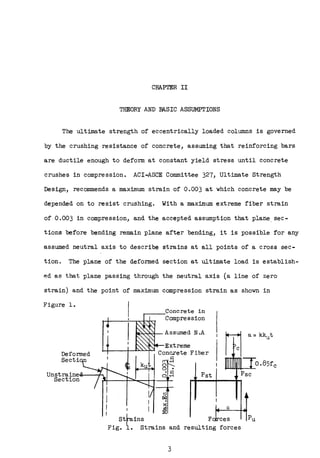
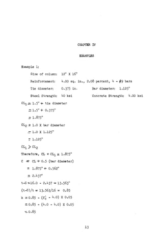
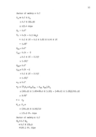
Here are the steps to solve this example using the analysis and derivations from Chapter III:
Given:
b = 12 in
t = 16 in
As = 4 sq in (4 #9 bars)
Perc = 2.08%
fy = 40 ksi
CL1 = 1.5 in
TD = 0.375 in
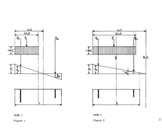
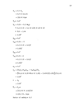
1) Compute kut:
kut = t - CL1 - TD/2 = 16 - 1.5 - 0.375/2 = 14.125 in
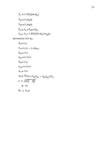
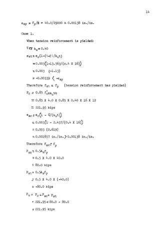
2) Assume various locations of neutral axis (x) and compute Pu and Mu:
x = 6 in
Pc = 0.85fc(12)(14

![25
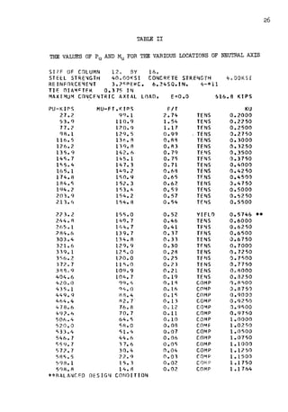
TABLE I
THE VALUES OF Pu AND Mu FOR THE VARIOUS LOCATIONS OF NEUTRAL AXIS
SllE OF C1LU~~ 12. BY 16.
STEEL STRE~~TH 40.00KSI CONC~ETE STRENGTH 4s00KSU
RFI~Fl~CF~~NT 2.0RPERC. 4.00SQ.IN. 4-•g
TIE DIA1f:TER Q.37'5 IN
M~XIMU~ cn~CF~TRIC AXIAL LnAO, E=O.O 559e4 KIPS
PlJ-KIPS
27.7
50.6
70.7
88.6
1or;. 1
116. 5
126.2
135. q
14"5.7
155.4
16"5. l
174.8
184.5
194.2
203.9
2u.n
2?3.3
225.5
255.4
271.5
287.0
302.2
317.0
331.5
l45.6
359.5
373.l
38A.5
399.7
412.7
42'5."i
438.l
450.6
463.0
475.2
487.3
499.3
511.2
"523.0
534.7
546. 3
5,.1. 0
MU-FT.KIPS
71.8
82.4
Ql.3
c.,g.o
LO 5. 7
109.8
112.8
115. 6
118. l
120.3
12?.2
123.9
12 5. 2
126.3
P7.2
127.7
12 8. 0
128.0
121.g
118. 4
114. 9
111.3
107.5
101.7
99.7
95.f>
ql.3
8 ti. 9
82.2
77.4
72.4
67.?
Al.A
56.2
50.4
44.3
3A.O
31.5
24.8
17.8
10.~
10.2
**BALANCED DESIGN CONDITION
E/T
1.95
1.22
0.97
0.84
0.75
0.11
0.67
0.64
0.61
o.sa
0.56
o.53
0.51
0.49
0.47
0.45
0.43
0.43
0. 3f,
0.33
0.30
0.213
0.25
0.2]
0.22
0.20
O.lA
0.11
0.15
0.14
0.13
0.12
0.10
o.oq
o.oa
0.01
0.06
0.05
0 • 0 1
t
o.p2
0.01
0.01
TENS
TENS
TENS
TENS
TENS
TENS
TENS
TENS
TENS
TENS
TENS
TENS
TENS
TENS
TENS
TENS
TENS
YIFLO
TENS
TFNS
TENS
TENS
TENS
TENS
TE"IS
TENS
TENS
COMP
COMP
CC:H-4P
COMP
COMP
COMP
COMP
co~~P
COMP
COMP
COMP
cn~P
CnMP
COll1P
COMP
KU
0.1750
0.2000
0.2250
0.2500
0.2750
0.3000
0.3250
0.3500
0.3750
0.4000
0.4250
0.4500
0.4750
0.5001)
0.5250
0.5500
0.5750
0.5806 ••
0. 6250
0.6500
0.6750
0.1000
0.7250
0.7500
0 .. 7750
0.801)0
J.8250
0.8500
0.8750
o.gooo
0 .9250
o.qsoo
0.9750
1.0000
1. 02 50
1.or;oo
1.0750
1.1000
1.1250
1.1500
l.1750
l.1764](https://image.slidesharecdn.com/thesis-1967r-k61u1-220516215123-bb54f6ea/85/Thesis-1967R-K61u-1-pdf-32-320.jpg)