COMPUTER NUMERICAL
CONTROL
PROGRAMMING BASICS
APrimer for the
SkillsUSA/VICA
Championships
Steve Krar Arthur Gill
Distributed to educational administrators,
instructors, students, and apprentices
with the compliments of
INDUSTRIAL PRESS, INC.
publishers of
MACHINERY’S HANDBOOK
“The Bible of the Machine Trades”
CONTENTS
SECTION PAGE
Foreword 1
Preface7
Cartesian Coordinate System 7
Machines Using CNC 9
Programming Systems 11
Point-to-Point or Continuous Path 13
Point-to-Point Positioning 14
Continuous Path (Contouring) 15
Interpolation 15
Programming Format 17
Programming for Positioning 23
Work Settings and Offsets 26
CNC Bench-Top Milling and Turning Centers 30
CNC Programming Hints — Milling 32
Milling and Drilling Programming 34
CNC Programming Hints – Turning 38
Fanuc Compatible Programming 39
Turning Programming 40
4.
7
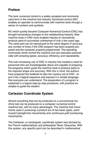
The term numericalcontrol is a widely accepted and commonly
used term in the machine tool industry. Numerical control (NC)
enables an operator to communicate with machine tools through a
series of numbers and symbols.
NC which quickly became Computer Numerical Control (CNC) has
brought tremendous changes to the metalworking industry. New
machine tools in CNC have enabled industry to consistently
produce parts to accuracies undreamed of only a few years ago.
The same part can be reproduced to the same degree of accuracy
any number of times if the CNC program has been properly pre-
pared and the computer properly programmed. The operating
commands which control the machine tool are executed automati-
cally with amazing speed, accuracy, efficiency, and repeatability.
The ever-increasing use of CNC in industry has created a need for
personnel who are knowledgeable about and capable of preparing
the programs which guide the machine tools to produce parts to
the required shape and accuracy. With this in mind, the authors
have prepared this textbook to take the mystery out of CNC - to
put it into a logical sequence and express it in simple language
that everyone can understand. The preparation of a program is
explained in a logical step-by-step procedure, with practical ex-
amples to guide the student.
Cartesian Coordinate System
Almost everything that can be produced on a conventional ma-
chine tool can be produced on a computer numerical control
machine tool, with its many advantages. The machine tool move-
ments used in producing a product are of two basic types: point-
to-point (straight-line movements) and continuous path (contouring
movements).
The Cartesian, or rectangular, coordinate system was devised by
the French mathematician and philosopher Rene’ Descartes. With
this system, any specific point can be described in mathematical
Preface
5.
8
terms from anyother point along three perpendicular axes. This
concept fits machine tools perfectly since their construction is
generally based on three axes of motion (X, Y, Z) plus an axis of
rotation. On a plain vertical milling machine, the X axis is the
horizontal movement (right or left) of the table, the Y axis is the
table cross movement (toward or away from the column), and the
Z axis is the vertical movement of the knee or the spindle. CNC
systems rely heavily on the use of rectangular coordinates be-
cause the programmer can locate every point on a job precisely.
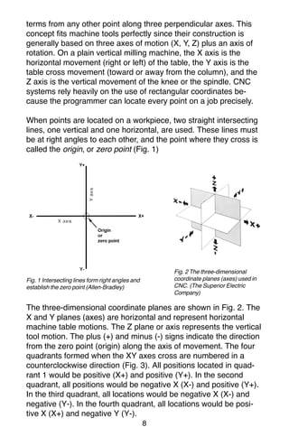
When points are located on a workpiece, two straight intersecting
lines, one vertical and one horizontal, are used. These lines must
be at right angles to each other, and the point where they cross is
called the origin, or zero point (Fig. 1)
Fig. 1 Intersecting lines form right angles and
establish the zero point (Allen-Bradley)
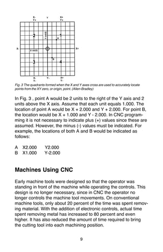
The three-dimensional coordinate planes are shown in Fig. 2. The
X and Y planes (axes) are horizontal and represent horizontal
machine table motions. The Z plane or axis represents the vertical
tool motion. The plus (+) and minus (-) signs indicate the direction
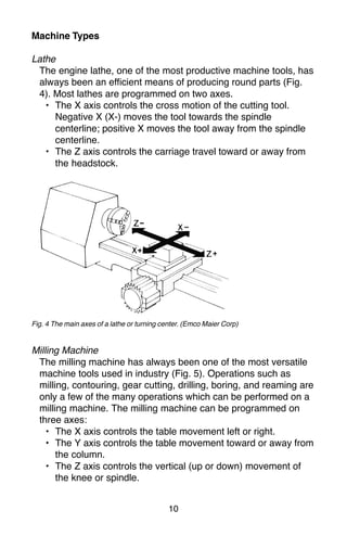
from the zero point (origin) along the axis of movement. The four
quadrants formed when the XY axes cross are numbered in a
counterclockwise direction (Fig. 3). All positions located in quad-
rant 1 would be positive (X+) and positive (Y+). In the second
quadrant, all positions would be negative X (X-) and positive (Y+).
In the third quadrant, all locations would be negative X (X-) and
negative (Y-). In the fourth quadrant, all locations would be posi-
tive X (X+) and negative Y (Y-).
Fig. 2 The three-dimensional
coordinate planes (axes) used in
CNC. (The Superior Electric
Company)
6.
9
Fig. 3 Thequadrants formed when the X and Y axes cross are used to accurately locate
points from the XY zero, or origin, point. (Allen-Bradley)
In Fig. 3 , point A would be 2 units to the right of the Y axis and 2
units above the X axis. Assume that each unit equals 1.000. The
location of point A would be X + 2.000 and Y + 2.000. For point B,
the location would be X + 1.000 and Y - 2.000. In CNC program-
ming it is not necessary to indicate plus (+) values since these are
assumed. However, the minus (-) values must be indicated. For
example, the locations of both A and B would be indicated as
follows:
A X2.000 Y2.000
B X1.000 Y-2.000
Machines Using CNC
Early machine tools were designed so that the operator was
standing in front of the machine while operating the controls. This
design is no longer necessary, since in CNC the operator no
longer controls the machine tool movements. On conventional
machine tools, only about 20 percent of the time was spent remov-
ing material. With the addition of electronic controls, actual time
spent removing metal has increased to 80 percent and even
higher. It has also reduced the amount of time required to bring
the cutting tool into each machining position.
7.
10
Machine Types
Lathe
The enginelathe, one of the most productive machine tools, has
always been an efficient means of producing round parts (Fig.
4). Most lathes are programmed on two axes.
• The X axis controls the cross motion of the cutting tool.
Negative X (X-) moves the tool towards the spindle
centerline; positive X moves the tool away from the spindle
centerline.
• The Z axis controls the carriage travel toward or away from
the headstock.
Fig. 4 The main axes of a lathe or turning center. (Emco Maier Corp)
Milling Machine
The milling machine has always been one of the most versatile
machine tools used in industry (Fig. 5). Operations such as
milling, contouring, gear cutting, drilling, boring, and reaming are
only a few of the many operations which can be performed on a
milling machine. The milling machine can be programmed on
three axes:
• The X axis controls the table movement left or right.
• The Y axis controls the table movement toward or away from
the column.
• The Z axis controls the vertical (up or down) movement of
the knee or spindle.
8.
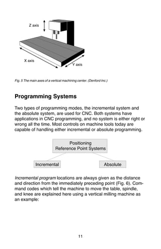
11
Fig. 5 Themain axes of a vertical machining center. (Denford Inc.)
Programming Systems
Two types of programming modes, the incremental system and
the absolute system, are used for CNC. Both systems have
applications in CNC programming, and no system is either right or
wrong all the time. Most controls on machine tools today are
capable of handling either incremental or absolute programming.
Incremental program locations are always given as the distance
and direction from the immediately preceding point (Fig. 6). Com-
mand codes which tell the machine to move the table, spindle,
and knee are explained here using a vertical milling machine as
an example:
X axis
Y axis
Z axis
Positioning
Reference Point Systems
Incremental Absolute
9.
12
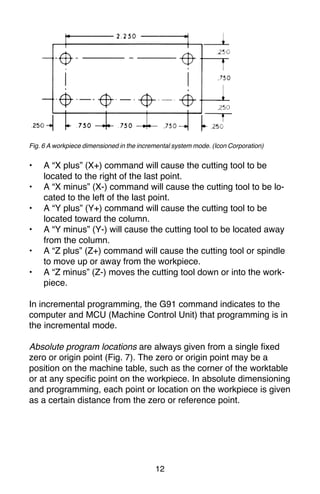
Fig. 6 Aworkpiece dimensioned in the incremental system mode. (Icon Corporation)
• A “X plus” (X+) command will cause the cutting tool to be
located to the right of the last point.
• A “X minus” (X-) command will cause the cutting tool to be lo-
cated to the left of the last point.
• A “Y plus” (Y+) command will cause the cutting tool to be
located toward the column.
• A “Y minus” (Y-) will cause the cutting tool to be located away
from the column.
• A “Z plus” (Z+) command will cause the cutting tool or spindle
to move up or away from the workpiece.
• A “Z minus” (Z-) moves the cutting tool down or into the work-
piece.
In incremental programming, the G91 command indicates to the
computer and MCU (Machine Control Unit) that programming is in
the incremental mode.
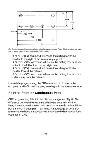
Absolute program locations are always given from a single fixed
zero or origin point (Fig. 7). The zero or origin point may be a
position on the machine table, such as the corner of the worktable
or at any specific point on the workpiece. In absolute dimensioning
and programming, each point or location on the workpiece is given
as a certain distance from the zero or reference point.
10.
13
Fig. 7 Aworkpiece dimensioned in the absolute system mode. Note: All dimensions are given
from a known point of reference. (Icon Corporation)
• A “X plus” (X+) command will cause the cutting tool to be
located to the right of the zero or origin point.
• A “X minus” (X-) command will cause the cutting tool to be lo-
cated to the left of the zero or origin point.
• A “Y plus” (Y+) command will cause the cutting tool to be
located toward the column.
• A “Y minus” (Y-) command will cause the cutting tool to be lo-
cated away from the column.
In absolute programming, the G90 command indicates to the
computer and MCU that the programming is in the absolute mode.
Point-to-Point or Continuous Path
CNC programming falls into two distinct categories (Fig. 8). The
difference between the two categories was once very distinct.
Now, however, most control units are able to handle both point-to-
point and continuous path machining. A knowledge of both pro-
gramming methods is necessary to understand what applications
each has in CNC.
11.
14
CNC Positioning
Systems
Point-to-Point
or
Positioning
Continuous Path
or
Contouring
Fig.8 Types of CNC positioning systems (Kelmar Associates)
Point-to-Point Positioning
Point-to-point positioning is used when it is necessary to accu-
rately locate the spindle, or the workpiece mounted on the ma-
chine table, at one or more specific Iocations to perform such
operations as drilling, reaming, boring, tapping, and punching (Fig.
9). Point-to-point positioning is the process of positioning from one
coordinate (XY) position or location to another, performing the
machining operation, and continuing this pattern until all the
operations have been completed at all programmed locations.
Fig. 9 The path followed by point-to-point positioning to reach various programmed points
(machining locations) on the XY axis. (Kelmar Associates)
In Fig. 9 point 1 to point 2 is a straight line, and the machine
moves only along the X axis; but points 2 and 3 require that
motion along both the X and Y axes takes place. As the distance
in the X direction is greater than in the Y direction, Y will reach its
12.
15
position first, leavingX to travel in a straight line for the remaining
distance. A similar motion takes place between points 3 and 4.
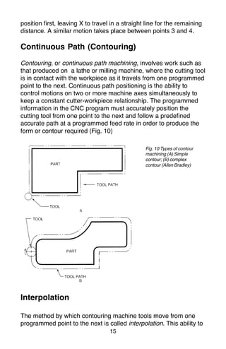
Continuous Path (Contouring)
Contouring, or continuous path machining, involves work such as
that produced on a lathe or milling machine, where the cutting tool
is in contact with the workpiece as it travels from one programmed
point to the next. Continuous path positioning is the ability to
control motions on two or more machine axes simultaneously to
keep a constant cutter-workpiece relationship. The programmed
information in the CNC program must accurately position the
cutting tool from one point to the next and follow a predefined
accurate path at a programmed feed rate in order to produce the
form or contour required (Fig. 10)
Interpolation
The method by which contouring machine tools move from one
programmed point to the next is called interpolation. This ability to
Fig. 10 Types of contour
machining (A) Simple
contour; (B) complex
contour (Allen Bradley)
13.
16
merge individual axispoints into a predefined tool path is built into
most of today’s MCUs. There are five methods of interpolation:
linear, circular, helical, parabolic, and cubic. All contouring controls
provide linear interpolation, and most controls are capable of both
linear and circular interpolation. Helical, parabolic, and cubic
interpolation are used by industries that manufacture parts which
have complex shapes, such as aerospace parts and dies for car
bodies.
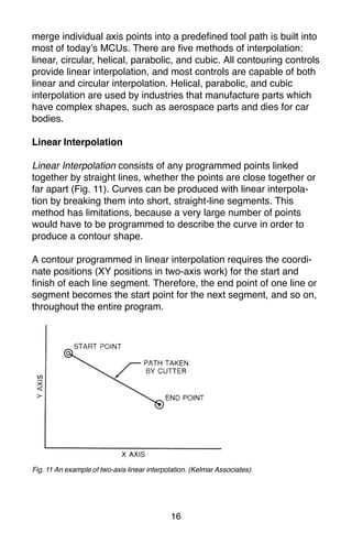
Linear Interpolation
Linear Interpolation consists of any programmed points linked
together by straight lines, whether the points are close together or
far apart (Fig. 11). Curves can be produced with linear interpola-
tion by breaking them into short, straight-line segments. This
method has limitations, because a very large number of points
would have to be programmed to describe the curve in order to
produce a contour shape.
A contour programmed in linear interpolation requires the coordi-
nate positions (XY positions in two-axis work) for the start and
finish of each line segment. Therefore, the end point of one line or
segment becomes the start point for the next segment, and so on,
throughout the entire program.
Fig. 11 An example of two-axis linear interpolation. (Kelmar Associates)
14.
17
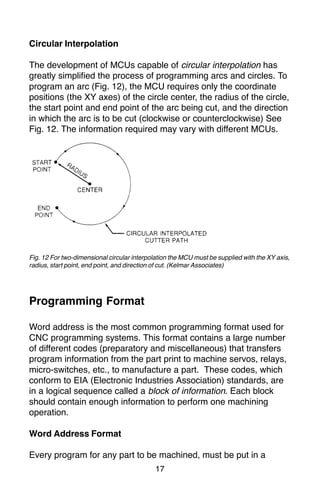
Fig. 12 Fortwo-dimensional circular interpolation the MCU must be supplied with the XY axis,
radius, start point, end point, and direction of cut. (Kelmar Associates)
Programming Format
Word address is the most common programming format used for
CNC programming systems. This format contains a large number
of different codes (preparatory and miscellaneous) that transfers
program information from the part print to machine servos, relays,
micro-switches, etc., to manufacture a part. These codes, which
conform to EIA (Electronic Industries Association) standards, are
in a logical sequence called a block of information. Each block
should contain enough information to perform one machining
operation.
Word Address Format
Every program for any part to be machined, must be put in a
Circular Interpolation
The development of MCUs capable of circular interpolation has
greatly simplified the process of programming arcs and circles. To
program an arc (Fig. 12), the MCU requires only the coordinate
positions (the XY axes) of the circle center, the radius of the circle,
the start point and end point of the arc being cut, and the direction
in which the arc is to be cut (clockwise or counterclockwise) See
Fig. 12. The information required may vary with different MCUs.
15.
18
format that themachine control unit can understand. The format
used on any CNC machine is built in by the machine tool builder
and is based on the type of control unit on the machine. A vari-
able-block format which uses words (letters) is most commonly
used. Each instruction word consists of an address character,
such as X, Y, Z, G, M, or S. Numerical data follows this address
character to identify a specific function such as the distance, feed
rate, or speed value.
The address code G90 in a program, tells the control that all
measurements are in the absolute mode. The code G91, tells the
control that measurements are in the incremental mode.
Codes
The most common codes used when programming CNC ma-
chines tools are G-codes (preparatory functions), and M codes
(miscellaneous functions). Other codes such as F, S, D, and T are
used for machine functions such as feed, speed, cutter diameter
offset, tool number, etc.
G-codes are sometimes called cycle codes because they refer to
some action occurring on the X, Y, and/or Z axis of a machine tool,
Fig. 13.
The G-codes are grouped into categories such as Group 01,
containing codes G00, G01, G02, G03. which cause some move-
ment of the machine table or head. Group 03 includes either
absolute or incremental programming, while Group 09 deals with
canned cycles.
A G00 code rapidly positions the cutting tool while it is above the
workpiece from one point to another point on a job. During the
rapid traverse movement, either the X or Y axis can be moved
individually or both axes can be moved at the same time. Although
the rate of rapid travel varies from machine to machine, it ranges
between 200 and 800 in./min (5 and 20 m/min).
16.
19
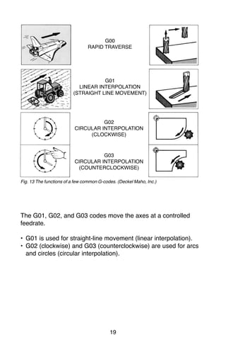
Fig. 13 Thefunctions of a few common G-codes. (Deckel Maho, Inc.)
The G01, G02, and G03 codes move the axes at a controlled
feedrate.
• G01 is used for straight-line movement (linear interpolation).
• G02 (clockwise) and G03 (counterclockwise) are used for arcs
and circles (circular interpolation).
G00
RAPID TRAVERSE
G01
LINEAR INTERPOLATION
(STRAIGHT LINE MOVEMENT)
G02
CIRCULAR INTERPOLATION
(CLOCKWISE)
G03
CIRCULAR INTERPOLATION
(COUNTERCLOCKWISE)
17.
20
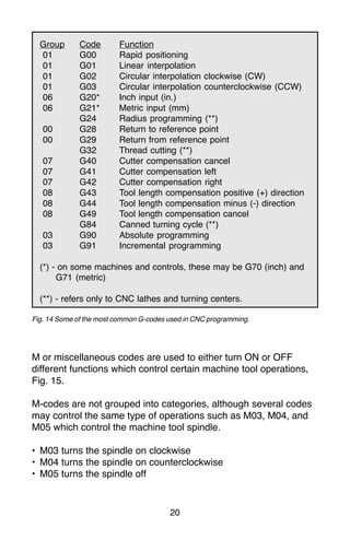
Group Code Function
01G00 Rapid positioning
01 G01 Linear interpolation
01 G02 Circular interpolation clockwise (CW)
01 G03 Circular interpolation counterclockwise (CCW)
06 G20* Inch input (in.)
06 G21* Metric input (mm)
G24 Radius programming (**)
00 G28 Return to reference point
00 G29 Return from reference point
G32 Thread cutting (**)
07 G40 Cutter compensation cancel
07 G41 Cutter compensation left
07 G42 Cutter compensation right
08 G43 Tool length compensation positive (+) direction
08 G44 Tool length compensation minus (-) direction
08 G49 Tool length compensation cancel
G84 Canned turning cycle (**)
03 G90 Absolute programming
03 G91 Incremental programming
(*) - on some machines and controls, these may be G70 (inch) and
G71 (metric)
(**) - refers only to CNC lathes and turning centers.
Fig. 14 Some of the most common G-codes used in CNC programming.
M or miscellaneous codes are used to either turn ON or OFF
different functions which control certain machine tool operations,
Fig. 15.
M-codes are not grouped into categories, although several codes
may control the same type of operations such as M03, M04, and
M05 which control the machine tool spindle.
• M03 turns the spindle on clockwise
• M04 turns the spindle on counterclockwise
• M05 turns the spindle off
18.
21
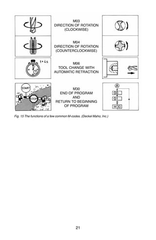
Fig. 15 Thefunctions of a few common M-codes. (Deckel Maho, Inc.)
M03
DIRECTION OF ROTATION
(CLOCKWISE)
M04
DIRECTION OF ROTATION
(COUNTERCLOCKWISE)
M06
TOOL CHANGE WITH
AUTOMATIC RETRACTION
M30
END OF PROGRAM
AND
RETURN TO BEGINNING
OF PROGRAM
19.
22
Code Function
M00 Programstop
M02 End of program
M03 Spindle start (forward CW)
M04 Spindle start (reverse CCW)
M05 Spindle stop
M06 Tool change
M08 Coolant on
M09 Coolant off
M10 Chuck - clamping (**)
M11 Chuck - unclamping (**)
M12 Tailstock spindle out (**)
M13 Tailstock spindle in (**)
M17 Toolpost rotation normal (**)
M18 Toolpost rotation reverse (**)
M30 End of tape and rewind
M98 Transfer to subprogram
M99 End of subprogram
(**) - refers only to CNC lathes and turning centers.
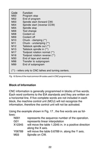
Fig. 16 Some of the most common M-codes used in CNC programming.
Block of Information
CNC information is generally programmed in blocks of five words.
Each word conforms to the EIA standards and they are written on
a horizontal line. If five complete words are not included in each
block, the machine control unit (MCU) will not recognize the
information, therefore the control unit will not be activated.
Using the example shown in Fig. 17 , the five words are as fol-
lows:
N001 represents the sequence number of the operation.
G01 represents linear interpolation
X12345 will move the table 1.2345 in. in a positive direction
along the X axis.
Y06789 will move the table 0.6789 in. along the Y axis.
M03 Spindle on CW.
20.
23
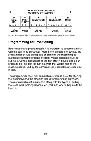
Fig. 17 Acomplete block of information consists of five words. (Kelmar Associates)
Programming for Positioning
Before starting to program a job, it is important to become familiar
with the part to be produced. From the engineering drawings, the
programmer should be capable of planning the machining se-
quences required to produce the part. Visual concepts must be
put into a written manuscript as the first step in developing a part
program, Fig. 18. It is the part program that will be sent to the
machine control unit by the computer, tape, diskette, or other input
media.
The programmer must first establish a reference point for aligning
the workpiece and the machine tool for programming purposes.
The manuscript must include this along with the types of cutting
tools and work-holding devices required, and where they are to be
located.
21.
24
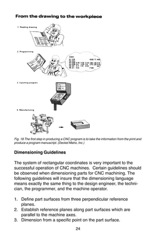
Fig. 18 Thefirst step in producing a CNC program is to take the information from the print and
produce a program manuscript. (Deckel Maho, Inc.)
Dimensioning Guidelines
The system of rectangular coordinates is very important to the
successful operation of CNC machines. Certain guidelines should
be observed when dimensioning parts for CNC machining. The
following guidelines will insure that the dimensioning language
means exactly the same thing to the design engineer, the techni-
cian, the programmer, and the machine operator.
1. Define part surfaces from three perpendicular reference
planes.
2. Establish reference planes along part surfaces which are
parallel to the machine axes.
3. Dimension from a specific point on the part surface.
22.
25
4. Dimension thepart clearly so that its shape can be understood
without making mathematical calculations or guesses.
5. Define the part so that a computer numerical control cutter
path can be easily programmed.
Machine Zero Point
The machine zero point can be set by three methods—by the
operator, manually by a programmed absolute zero shift, or by
work coordinates, to suit the holding fixture or the part to be
machined.
MANUAL SETTING - The operator can use the MCU controls to
locate the spindle over the desired part zero and then set the X
and Y coordinate registers on the console to zero.
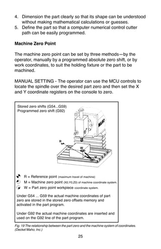
Fig. 19 The relationship between the part zero and the machine system of coordinates.
(Deckel Maho, Inc.)
Stored zero shifts (G54...G59)
Programmed zero shift (G92)
R = Reference point (maximum travel of machine)
M = Machine zero point (X0,Y0,Z0) of machine coordinate system.
W = Part zero point workpiece coordinate system.
Under G54 ... G59 the actual machine coordinates of part
zero are stored in the stored zero offsets memory and
activated in the part program.
Under G92 the actual machine coordinates are inserted and
used on the G92 line of the part program.
23.
26
ABSOLUTE ZERO SHIFT- The absolute zero shift can change
the position of the coordinate system by a command in the CNC
program. The programmer first sends the machine spindle to
home zero position by a G28 command in the program. Then
another command (G92 for absolute zero shift) tells the MCU
how far from the home zero location, the coordinate system origin
is to be positioned, Fig. 19.
The sample commands may be as follows:
N1 G28 X0 Y0 Z0 (sends spindle to home zero position)
N2 G92 X4.000 Y5.000 Z6.000 (the position the machine will
reference as part zero)
Work Settings and Offsets
All CNC machine tools require some form of work setting, tool
setting, and offsets (compensation) to place the cutter and work in
the proper relationship. Compensation allows the programmer to
make adjustments for unexpected tooling and setup conditions.
Work Coordinates
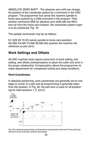
In absolute positioning, work coordinates are generally set on one
edge or corner of a part and all programming is generally taken
from this position. In Fig. 20, the part zero is used for all position-
ing for hole locations 1, 2, and 3.
Fig. 20 In absolute programming, all dimensions must be taken from the XY zero at the top
left-hand corner of the part. (Kelmar Associates)
24.
27
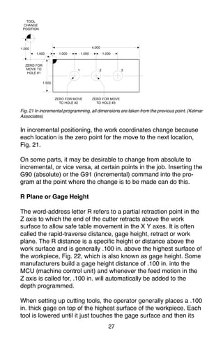
Fig. 21 Inincremental programming, all dimensions are taken from the previous point. (Kelmar
Associates)
In incremental positioning, the work coordinates change because
each location is the zero point for the move to the next location,
Fig. 21.
On some parts, it may be desirable to change from absolute to
incremental, or vice versa, at certain points in the job. Inserting the
G90 (absolute) or the G91 (incremental) command into the pro-
gram at the point where the change is to be made can do this.
R Plane or Gage Height
The word-address letter R refers to a partial retraction point in the
Z axis to which the end of the cutter retracts above the work
surface to allow safe table movement in the X Y axes. It is often
called the rapid-traverse distance, gage height, retract or work
plane. The R distance is a specific height or distance above the
work surface and is generally .100 in. above the highest surface of
the workpiece, Fig. 22, which is also known as gage height. Some
manufacturers build a gage height distance of .100 in. into the
MCU (machine control unit) and whenever the feed motion in the
Z axis is called for, .100 in. will automatically be added to the
depth programmed.
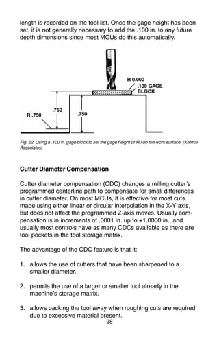
When setting up cutting tools, the operator generally places a .100
in. thick gage on top of the highest surface of the workpiece. Each
tool is lowered until it just touches the gage surface and then its
25.
28
length is recordedon the tool list. Once the gage height has been
set, it is not generally necessary to add the .100 in. to any future
depth dimensions since most MCUs do this automatically.
Fig. 22 Using a .100 in. gage block to set the gage height or R0 on the work surface. (Kelmar
Associates)
Cutter Diameter Compensation
Cutter diameter compensation (CDC) changes a milling cutter’s
programmed centerline path to compensate for small differences
in cutter diameter. On most MCUs, it is effective for most cuts
made using either linear or circular interpolation in the X-Y axis,
but does not affect the programmed Z-axis moves. Usually com-
pensation is in increments of .0001 in. up to +1.0000 in., and
usually most controls have as many CDCs available as there are
tool pockets in the tool storage matrix.
The advantage of the CDC feature is that it:
1. allows the use of cutters that have been sharpened to a
smaller diameter.
2. permits the use of a larger or smaller tool already in the
machine’s storage matrix.
3. allows backing the tool away when roughing cuts are required
due to excessive material present.
26.
29
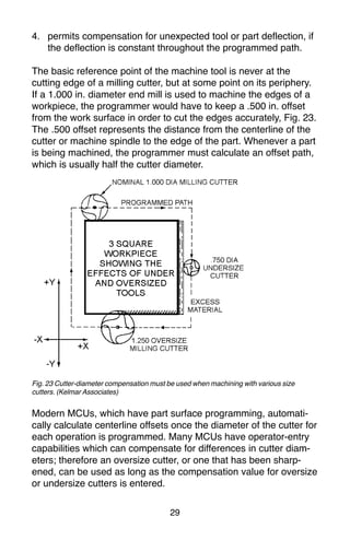
4. permits compensationfor unexpected tool or part deflection, if
the deflection is constant throughout the programmed path.
The basic reference point of the machine tool is never at the
cutting edge of a milling cutter, but at some point on its periphery.
If a 1.000 in. diameter end mill is used to machine the edges of a
workpiece, the programmer would have to keep a .500 in. offset
from the work surface in order to cut the edges accurately, Fig. 23.
The .500 offset represents the distance from the centerline of the
cutter or machine spindle to the edge of the part. Whenever a part
is being machined, the programmer must calculate an offset path,
which is usually half the cutter diameter.
Fig. 23 Cutter-diameter compensation must be used when machining with various size
cutters. (Kelmar Associates)
Modern MCUs, which have part surface programming, automati-
cally calculate centerline offsets once the diameter of the cutter for
each operation is programmed. Many MCUs have operator-entry
capabilities which can compensate for differences in cutter diam-
eters; therefore an oversize cutter, or one that has been sharp-
ened, can be used as long as the compensation value for oversize
or undersize cutters is entered.
27.
30
CNC Bench-Top Millingand Turning Centers
Bench-top teaching machines are well suited for teaching
purposes because neither the student or the teacher are intimated
by the size or complexity of the machines. They are easy to
program and perform machining operations similar to industrial
machines with smaller workpiece and lighter cuts. Bench-top
machines are relatively inexpensive and ideal for teaching basic
CNC programming.
Vertical machining centers and turning centers are the most
common CNC machines used in industry. For teaching purposes,
two types of CNC Bench-Top machines, the lathe and the mill, will
be used because they use the same basic programming features
and the Fanuc compatible controls as industrial machines. Most of
the G and M codes are the same for CNC Bench-top teaching
machines and industrial machines. Since programming codes do
vary slightly with manufacturers, it is always wise to
consult the programming manual for each specific machine to
avoid crashes or scrap work.
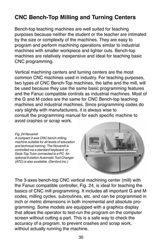
The 3-axes bench-top CNC vertical machining center (mill) with
the Fanuc compatible controller, Fig. 24, is ideal for teaching the
basics of CNC mill programming. It includes all important G and M
codes, milling cycles, subroutines, etc. and can be programmed in
inch or metric dimensions in both incremental and absolute pro-
gramming. Some models are equipped with a graphics display
that allows the operator to test-run the program on the computer
screen without cutting a part. This is a safe way to check the
accuracy of a program, to prevent crashes and scrap work,
without actually running the machine.
Fig. 24 Novamill
A compact 3 axis CNC bench milling
machine suitable for all levels of education
and technical training. The Novamill is
controlled via a standard keyboard or
Desk-Top Tutor connected to a PC. An
optional 6 station Automatic Tool Changer
(ATC) is also available. (Denford Inc.)
28.
31
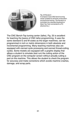
The CNC Bench-Topturning center (lathe), Fig. 25 is excellent
for teaching the basics of CNC lathe programming. It uses the
same standard G and M codes as the larger machines, can be
programmed in inch or metric dimensions in both absolute and
incremental programming. Many teaching machines also are
equipped with canned cycle processing and canned thread-cutting
cycles. Some models are equipped with a graphic display that
allows a student to simulate (test run) the cutting action of the
CNC program on the computer screen without actually cutting a
part on the machine. This allows the student to check the program
for accuracy and make corrections which avoids machine crashes,
damage, and scrap parts.
Fig. 25 Novaturn
A compact 2 axis CNC bench turning
center suitable for all levels of education
and technical training. The Novaturn is
controlled via a standard keyboard or
Desk-Top Tutor connected to a PC.
(Denford Inc.)
29.
32
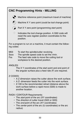
CNC Programming Hints- MILLING
Machine reference point (maximum travel of machine)
Machine X Y zero point (could be tool change point)
Part X Y zero point (programming start point)
Indicates the tool change position. A G92 code will
reset the axis register position coordinates to this
position.
For a program to run on a machine, it must contain the follow-
ing codes:
M03 To start the spindle/cutter revolving.
Sxxx The spindle speed code to set the r/min.
Fxx The feed rate code to move the cutting tool or
workpiece to the desired position.
ANGLES:
The X Y coordinates of the start point and end point of
the angular surface plus a feed rate (F) are required.
Z CODES:
• A Z dimension raises the cutter above the work surface.
• A Z- dimension feeds the cutter into the work surface.
• Z.100 is the recommended retract distance above the
work surface before a rapid move (G00) is made to
another location.
RADII / CONTOUR Requirements:
• The start point of the arc (XY coordinates)
• The direction of cutter travel (G02 or G03)
• The end point of the arc (XY coordinates)
• The center point of the arc (IJ coordinates) or the arc
radius)
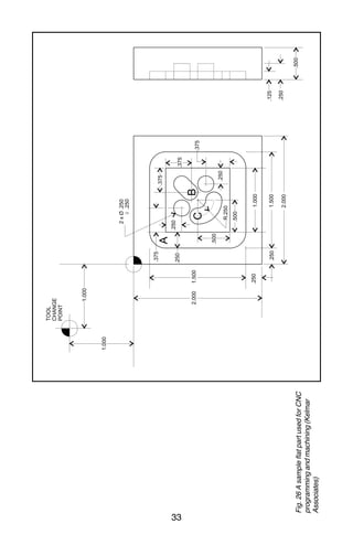
34
Milling and DrillingProgramming
Program Notes: (Fig. 26)
• Program in the absolute mode starting at the tool change
position at the top left corner of the print.
• The material is aluminum (300 CS), feedrate 10 in/min.
• The cutting tool is a .250 in. diameter high speed steel 2-flute
end mill.
• Mill the 1 in. square slot.
• Drill the two .250 in. diameter holes, .250 in. deep.
• Mill the .250 in. wide angular slot, .125 in. deep.
• Mill the .250 in. wide circular groove, .125 in. deep.
• After the job is completed, return to the tool change position.
Programming:
% (rewind stop code / parity check)
2000 (program number)
N5 G92 X-1.000 Y1.000 Z1.000
G92 programmed offset of reference point (tool change
position)
X-1.000 tool set at 1.000 to the left of the part.
Y1.000 tool set at 1.000 above the top edge of the part.
Z1.000 the end of the cutter is 1.000 above the top surface
of the part.
N10 G20 G90
G20 inch data input.
G90 absolute programming mode.
N15 M06 T01
M06 tool change command.
T01 tool no. 1 (.250 diameter, 2-flute end mill).
N20 S2000 M03
S2000 spindle speed set at 2000 r/min.
M03 spindle on clockwise.
32.
35
N25 G00 X0Y0 Z.100
G00 rapid traverse rate to X0 Y0 at the top left corner of
the part.
Z.100 tool rapids down to within .100 of the work surface.
Machining the square groove
N30 X.375 Y-.375
tool rapids to position A.
N35 G01 Z-.125 F10
G01 linear interpolation.
Z-.125 tool feeds .125 below the work surface.
F10 feed rate set at 10 in./min.
N40 X1.625 Y-.375
X1.625 top groove cut to the right hand end.
Y-.375 measurement did not change because it was set in
block N30.
N45 Y-1.625
Y-1.625 right hand side of the groove cut.
N50 X.375
X.375 bottom groove cut to the left side.
N55 Y-.375
Y-.375 left-hand side of groove cut; this completes the
groove.
N60 G00 Z.100
G00 rapid traverse mode.
Z.100 tool rapids to .100 above work surface.
Hole Drilling
N65 G00 X.875 Y-.750
tool rapids to the top left hole location.
33.
36
N70 G01 Z-.250F10
tool feeds .250 into work at 10 in./min. to drill the
first hole.
N75 G00 Z.100
tool rapids out of hole to .100 above work surface.
N80 X1.250 Y-1.125
tool rapids to second hole location.
N85 G01 Z-.250 F10
tool feeds .250 into work at 10 in./min. to drill the
second hole.
N90 G00 Z.100
tool rapids out of hole to .100 above work surface.
Machining the Angular Slot
N95 X1.125 Y-.875 (location B)
tool rapids to the start of the angular slot.
N100 G01 Z-.125 F10
G01 linear interpolation.
Z-.125 tool feeds to .125 below the work surface.
F10 feed rate set at 10 in./min.
N105 X1.250 Y-.750
angular slot cut to top right corner.
N110 G00 Z.100
tool rapids to .100 above work surface.
Machining the Circular Groove
N115 X.750 Y-1.000 (location C)
tool rapids to start of circular groove.
N120 G01 Z-.125 F10
tool feeds to .125 below the work surface.
34.
37
N125 G03 X1.000Y-1.250 R.250
G03 circular interpolation counterclockwise
X & Y location of end of circular groove.
R.250 radius of arc is .250.
N130 G00 Z.100
tool rapids to .100 above work surface.
N135 X-1.000 Y1.000
tool rapids back to tool change position.
N140 M05
M05 spindle turned off.
N145 M30
M30 end of program
35.
38
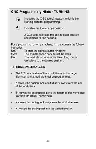
CNC Programming Hints- TURNING
Indicates the X Z 0 (zero) location which is the
starting point for programming.
Indicates the tool-change position.
A G92 code will reset the axis register position
coordinates to this position.
For a program to run on a machine, it must contain the follow-
ing codes:
M03 To start the spindle/cutter revolving.
Sxxx The spindle speed code to set the r/min.
Fxx The feedrate code to move the cutting tool or
workpiece to the desired position.
TAPERS/BEVELS/ANGLES
• The X Z coordinates of the small diameter, the large
diameter, and a feedrate must be programmed.
• Z moves the cutting tool longitudinally away from the end
of the workpiece.
• Z- moves the cutting tool along the length of the workpiece
towards the chuck (headstock).
• X moves the cutting tool away from the work diameter.
• X- moves the cutting tool into the work diameter.
36.
39
Fanuc Compatible Programming
Theprogramming for the Fanuc compatible control is the one
most commonly used in industry. Although many controls are
similar to the Fanuc control, there are some differences. A few of
the main differences are:
1.) The G28 code is used to set the programmed offset of the
reference point.
2.) Codes are modal and do not have to be repeated in every
sequence line.
3.) All dimensions are entered as decimals.
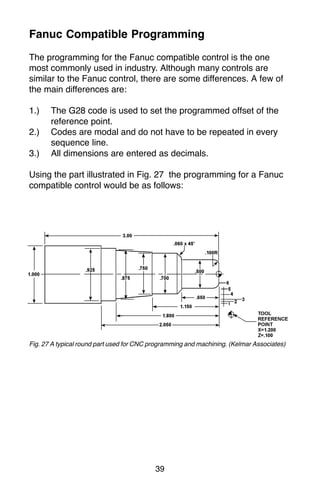
Using the part illustrated in Fig. 27 the programming for a Fanuc
compatible control would be as follows:
Fig. 27 A typical round part used for CNC programming and machining. (Kelmar Associates)
37.
40
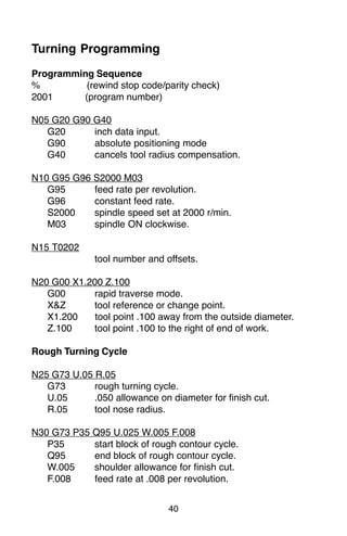
Turning Programming
Programming Sequence
%(rewind stop code/parity check)
2001 (program number)
N05 G20 G90 G40
G20 inch data input.
G90 absolute positioning mode
G40 cancels tool radius compensation.
N10 G95 G96 S2000 M03
G95 feed rate per revolution.
G96 constant feed rate.
S2000 spindle speed set at 2000 r/min.
M03 spindle ON clockwise.
N15 T0202
tool number and offsets.
N20 G00 X1.200 Z.100
G00 rapid traverse mode.
X&Z tool reference or change point.
X1.200 tool point .100 away from the outside diameter.
Z.100 tool point .100 to the right of end of work.
Rough Turning Cycle
N25 G73 U.05 R.05
G73 rough turning cycle.
U.05 .050 allowance on diameter for finish cut.
R.05 tool nose radius.
N30 G73 P35 Q95 U.025 W.005 F.008
P35 start block of rough contour cycle.
Q95 end block of rough contour cycle.
W.005 shoulder allowance for finish cut.
F.008 feed rate at .008 per revolution.
38.
41
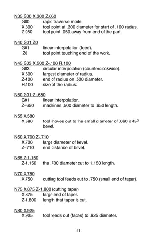
N35 G00 X.300Z.050
G00 rapid traverse mode.
X.300 tool point at .300 diameter for start of .100 radius.
Z.050 tool point .050 away from end of the part.
N40 G01 Z0
G01 linear interpolation (feed).
Z0 tool point touching end of the work.
N45 G03 X.500 Z-.100 R.100
G03 circular interpolation (counterclockwise).
X.500 largest diameter of radius.
Z-100 end of radius on .500 diameter.
R.100 size of the radius.
N50 G01 Z-.650
G01 linear interpolation.
Z-.650 machines .500 diameter to .650 length.
N55 X.580
X.580 tool moves out to the small diameter of .060 x 45O
bevel.
N60 X.700 Z-.710
X.700 large diameter of bevel.
Z-.710 end distance of bevel.
N65 Z-1.150
Z-1.150 the .700 diameter cut to 1.150 length.
N70 X.750
X.750 cutting tool feeds out to .750 (small end of taper).
N75 X.875 Z-1.800 (cutting taper)
X.875 large end of taper.
Z-1.800 length that taper is cut.
N80 X.925
X.925 tool feeds out (faces) to .925 diameter.
39.
42
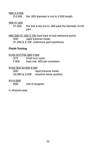
N85 Z-2.050
Z-2.050 the.925 diameter is cut to 2.050 length.
N90 X1.050
X1.050 the tool is fed out to .050 past the diameter of the
part.
N95 G00 X1.200 Z.100 (tool back to tool reference point)
G00 rapid traverse mode.
X1.200 & Z.100 (reference point positions)
Finish Turning
N100 G72 P35 Q95 F.005
G72 finish turn cycle.
F.005 feed rate .005 per revolution.
N105 G00 X2.000 Z.500
G00 rapid traverse mode.
X2.000 & Z.500 machine home position.
N110 M30
M30 end of program
% Rewind code.