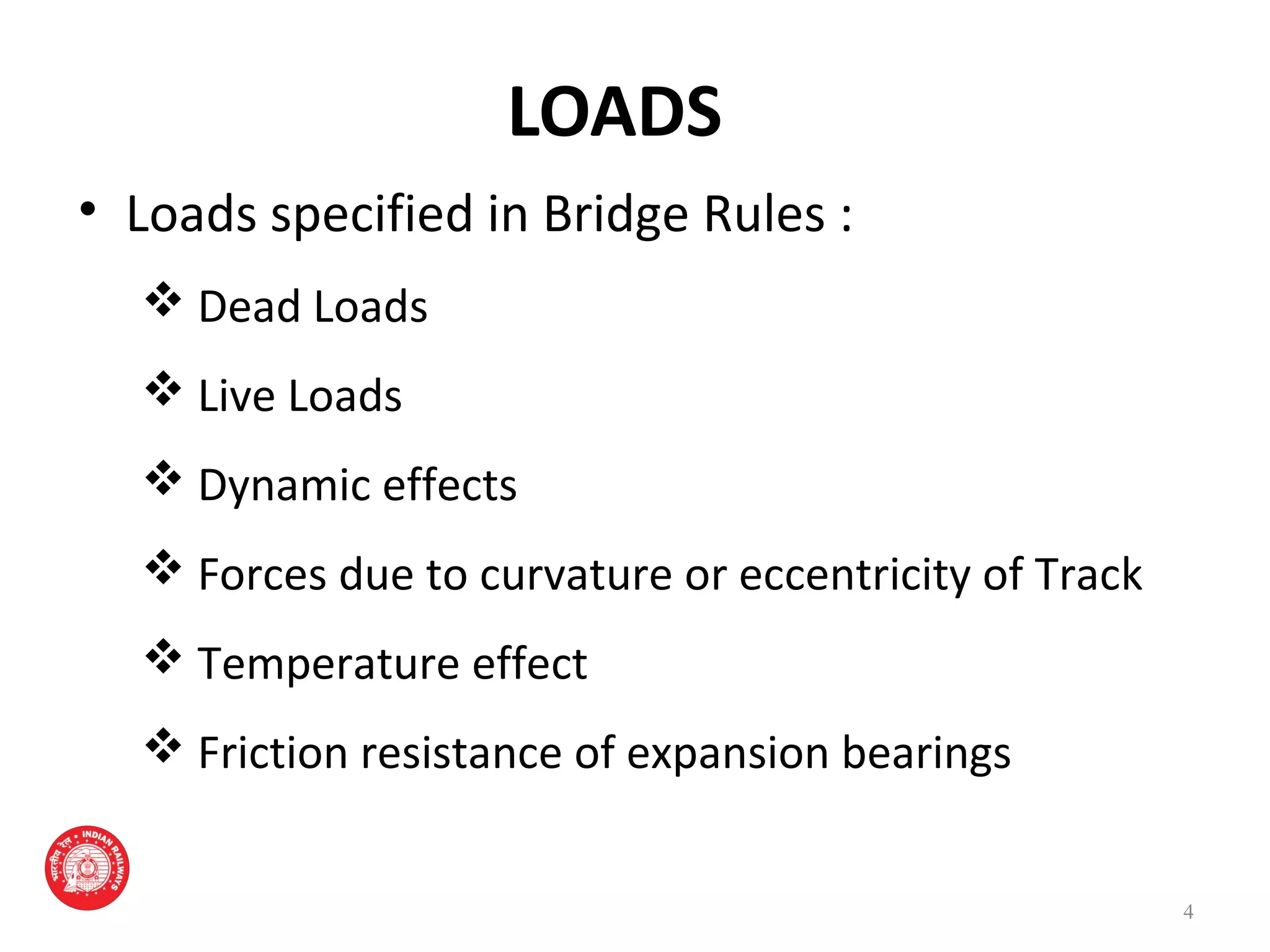
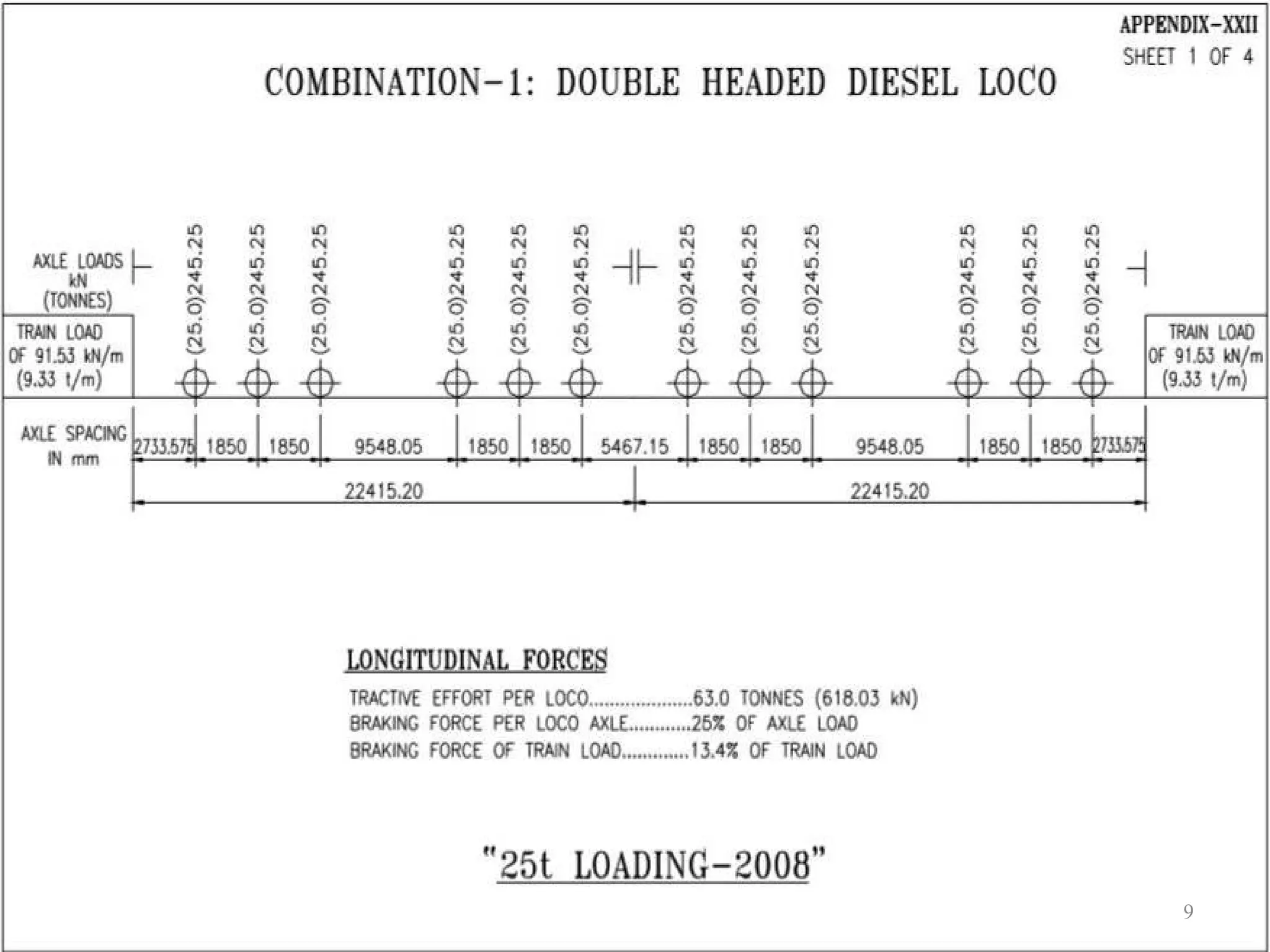
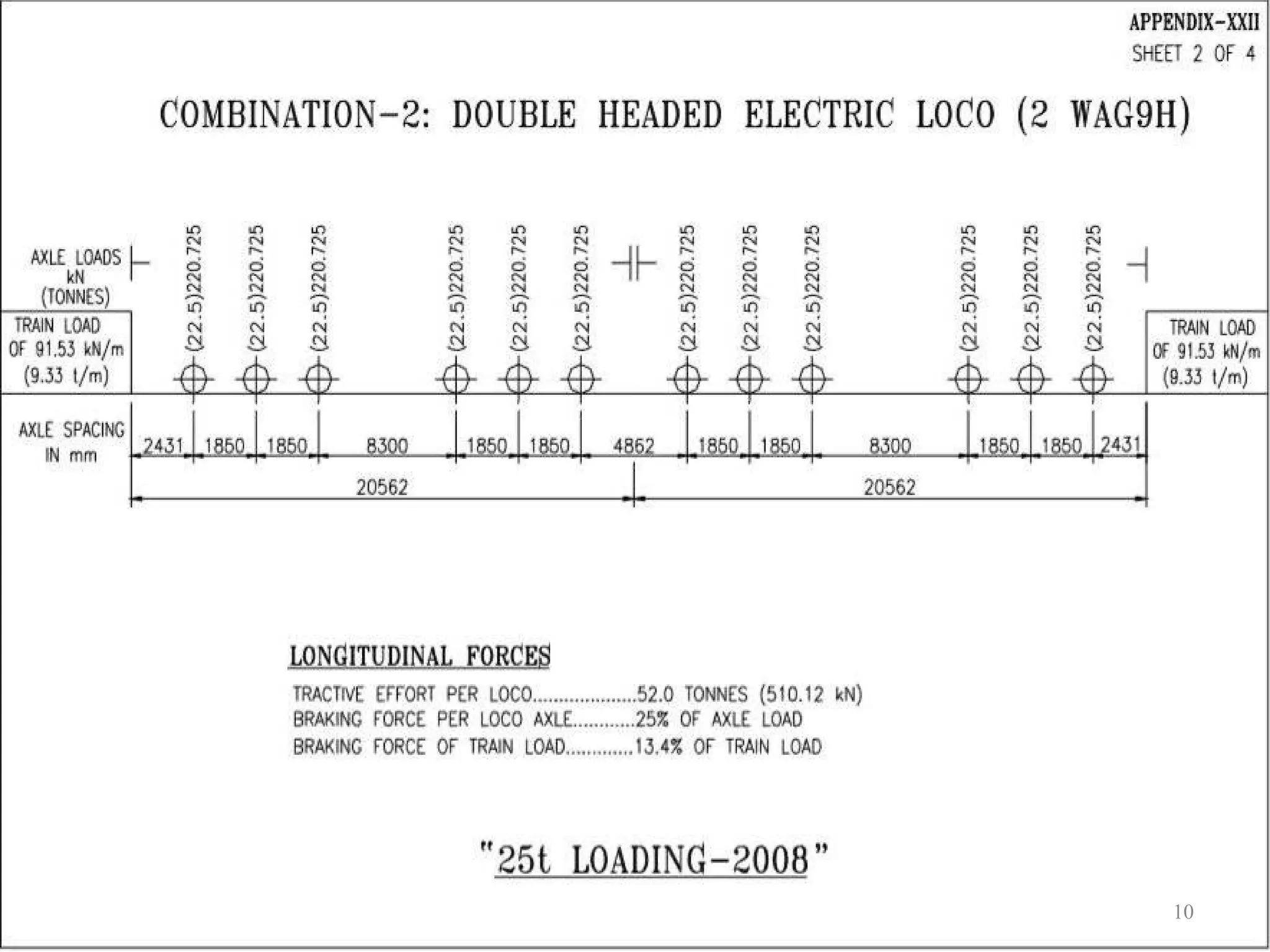
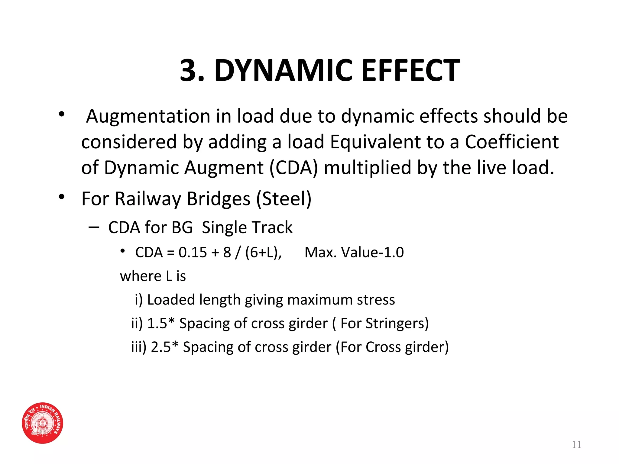
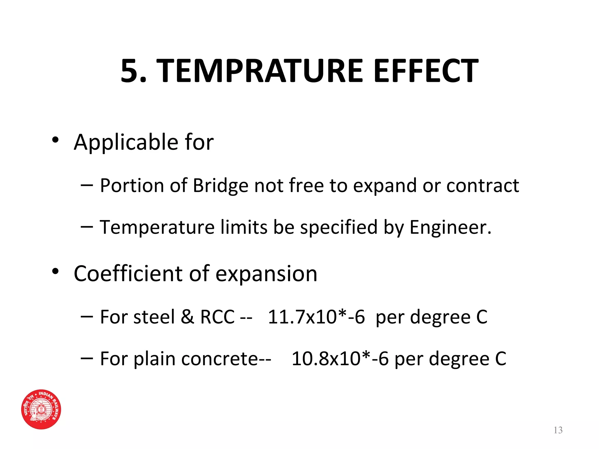
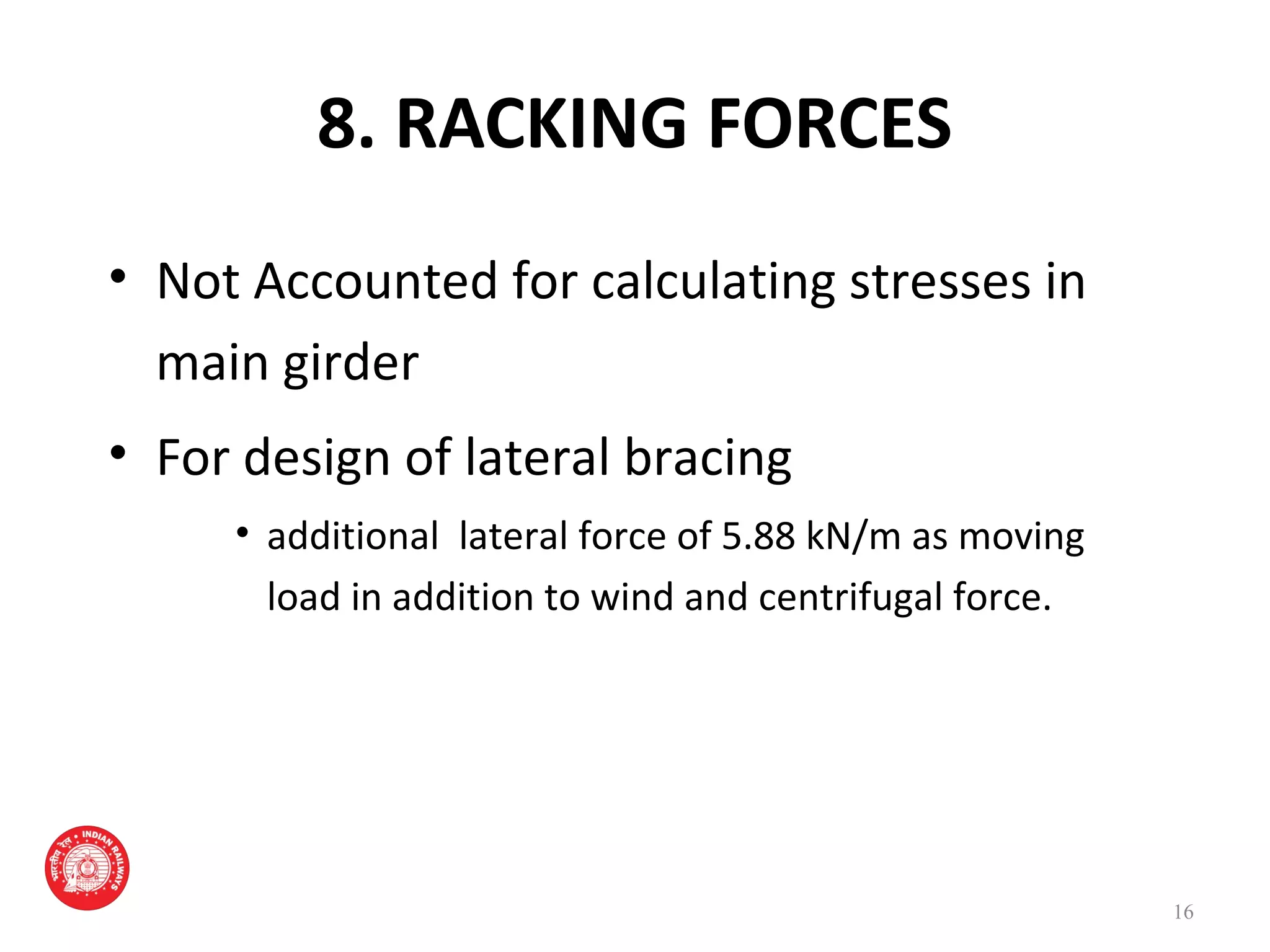
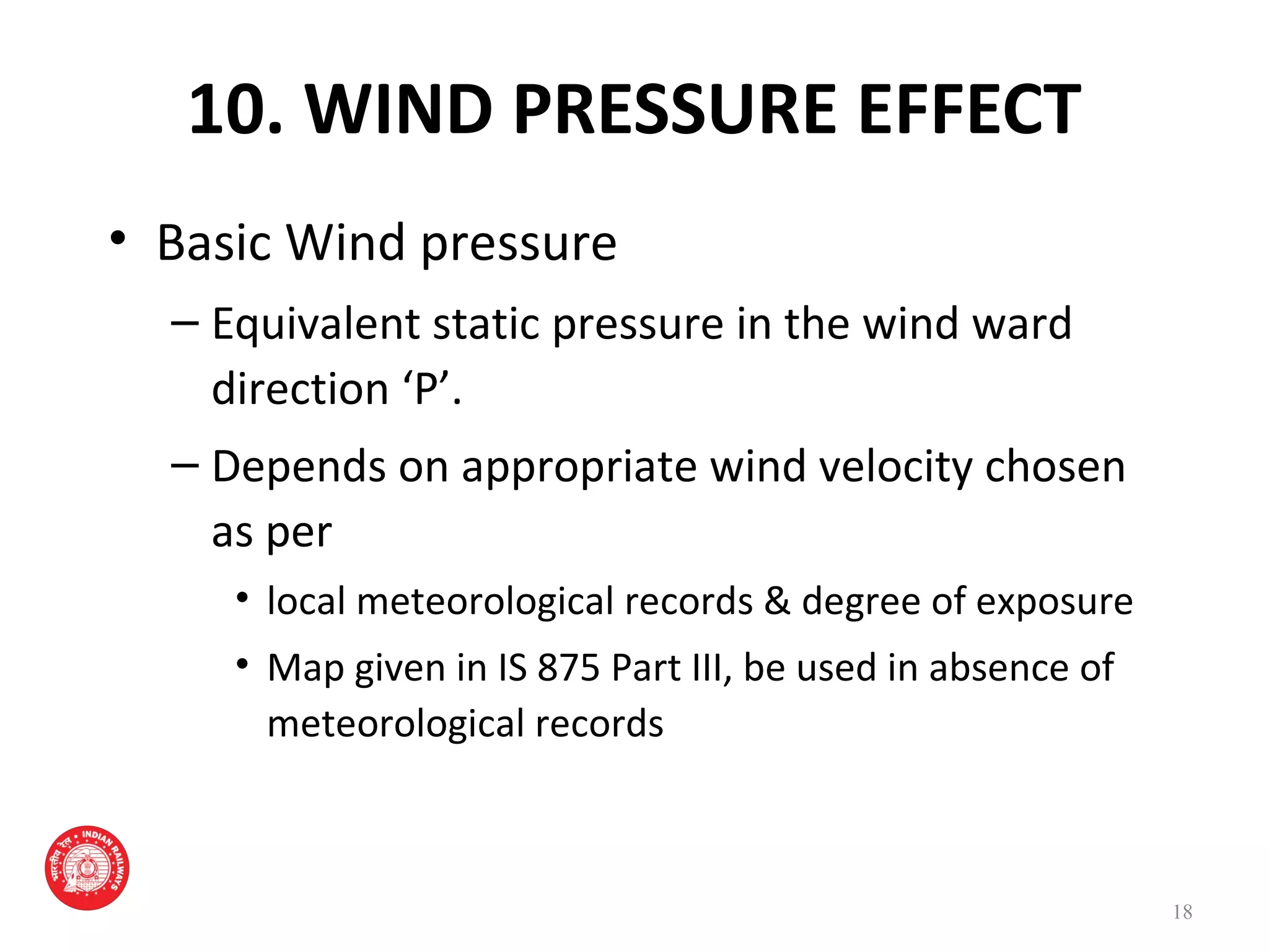
BRIDGE RULES
Presented By
Mohammad Furqan
J.E (Bridge),PA
Presented To
Mohammed Faiz
XEN(B & F) MMR
1
GOVERNMENT OF INDIA
MINISTRY OF RAILWAYS
(Railway Board)
PURPOSE
• Specifying the rules/loads for
– Design of superstructure & substructure of
Bridges
– Assessing the strength of existing Bridges
2
SCOPE
• Loads specified shall be used for
– All Railway Bridges
– Turn Table girders
– Foot Bridges but excluding Road Bridges
• Design detailing shall be controlled by
appropriate code of practice
3
LOADS
• Loads specified in Bridge Rules :
 Dead Loads
 Live Loads
 Dynamic effects
 Forces due to curvature or eccentricity of Track
 Temperature effect
 Friction resistance of expansion bearings
4
LOADS CONT.
 Longitudinal Forces
 Racking forces
 Forces on parapets
 Wind pressure effects
 Forces & Effects due to earthquake
 Erection forces and effects
 Derailment loads
 PQRS loads
5
1. DEAD LOAD
• Weight of structure
• Permanent Load carried on it
6
2. LIVE LOAD
• History
• Present Live Loads
– For Railway Bridges / Rail-cum-road Bridge
– For Foot Bridge / Footpath 4.8 KN/m²
7
BRIDGE LOADING STANDARDS HISTORY
FOR BG (1676 mm)
LoadingLoading
Std.Std.
YearYear Max. Axle LoadMax. Axle Load
Engine (t)Engine (t)
TrailingTrailing
LoadLoad
(t/m)(t/m)
Long. Force (t)Long. Force (t)
TractiveTractive
Effort (t)Effort (t)
Braking ForceBraking Force
Std. BStd. B 19031903 18.018.0 1.20 t/ft1.20 t/ft -- --
BGMLBGML 19261926 22.922.9 7.677.67 47.647.6 10% of T.L.10% of T.L.
RBGRBG 19751975 22.522.5 7.677.67 7575 20% of T.L.20% of T.L.
MBGMBG 19871987 2525 8.258.25 100100 13.4% of T.L. + 25% of13.4% of T.L. + 25% of
Axle Load.Axle Load.
HMHM 19951995 3030 12.0012.00 135135 -do--do-
25 T25 T 20082008 2525 9.339.33 126126 -do--do-
DFCDFC 20082008 32.532.5 12.1312.13 126126 -do--do-
8
9
10
3. DYNAMIC EFFECT
• Augmentation in load due to dynamic effects should be
considered by adding a load Equivalent to a Coefficient
of Dynamic Augment (CDA) multiplied by the live load.
• For Railway Bridges (Steel)
– CDA for BG Single Track
• CDA = 0.15 + 8 / (6+L), Max. Value-1.0
where L is
i) Loaded length giving maximum stress
ii) 1.5* Spacing of cross girder ( For Stringers)
iii) 2.5* Spacing of cross girder (For Cross girder)
11
4. FORCES DUE TO CURVATURE OR
ECCENTRICITY OF TRACK
• On ballasted deck, even on straight line
– Designed for 100mm eccentricity
• On a curved Bridge
– Designed for centrifugal action of moving load
taking all tracks occupied
– Horizontal load due to centrifugal force is
C = WV² /12.95R t/m run
12
5. TEMPRATURE EFFECT
• Applicable for
– Portion of Bridge not free to expand or contract
– Temperature limits be specified by Engineer.
• Coefficient of expansion
– For steel & RCC -- 11.7x10*-6 per degree C
– For plain concrete-- 10.8x10*-6 per degree C
13
6. FRICTIONAL RESTISTANCE OF EXPANSION
BEARING
• Coefficient of frictional resistance of
expansion bearings are
– Roller bearing 0.03
– Sliding bearings of steel on
• Steel on Cast Iron or Steel 0.25
• Steel on Ferro bestos 0.20
• Steel on Hard copper alloy 0.15
– Sliding bearing of PTFE / Elastomeric 0.10
14
7. LONGITUDINAL FORCES
• One or more of following reasons
– Tractive Efforts
– Braking Force
– Resistance to movement of bearing
– Due to LWR over bridges.
– should not be more than the limiting resistance
at the bearing.
15
8. RACKING FORCES
• Not Accounted for calculating stresses in
main girder
• For design of lateral bracing
• additional lateral force of 5.88 kN/m as moving
load in addition to wind and centrifugal force.
16
9. FORCES ON PARAPETS
• Minimum height
– one meter above adjacent roadway/foot way
surface
• Designed for a lateral horizontal and a vertical
force of
– 1.47 kN/m applied simultaneous at top of the
railing/parapet
17
10. WIND PRESSURE EFFECT
• Basic Wind pressure
– Equivalent static pressure in the wind ward
direction ‘P’.
– Depends on appropriate wind velocity chosen
as per
• local meteorological records & degree of exposure
• Map given in IS 875 Part III, be used in absence of
meteorological records
18
11. Wind Pressure Effect Cont.
• Wind Pressure for railway / foot bridges
– Wind pressure specified shall apply to
• all loaded / unloaded bridges provided
• Bridges does not carry live loads when wind
pressure at deck level exceeds 1.47 kN/m² For BG.
19
12. Forces and Effect due to
Earthquake
• Seismic Force
– Acts in three mutually perpendicular directions
• Horizontal (Two Directions)
• Vertical
– For determining seismic forces country is
divided in 4 zones
• Basic horizontal Seismic Coefficient defined for
each zones
20
21
Seismic Force Cont.
– Slab, box and pipe culvert need not be designed for
seismic forces
– Consideration of Seismic forces for design of bridge in
different zone
Zone II(.02) & III(.04) -for bridges of overall length
>60m or span >15m
Zone IV(.05) &V(.08) -all bridges
22
13. ERECTION FORCES AND
EFFECTS
• Erection Forces to be considered
– Weight of all permanent and temporary material
– All other forces and effects which can operate on
any part during erection
• Allowance be made in design for stresses set
up in any member during erection.
23
12. DERAIRELMENT LOADS
• Derailment loads for BG for ballasted deck
bridges as per appendix XXV.
• Load specified shall be applied at top of
ballast
• Load assumed to disperse at a slope of half
horizontal to one vertical.
24
25
13. LOAD DUE TO PLASSER’S QUICK
RELAY SYSTEM (PQRS)
• PQRS is a process wherein old rail along
with sleeper removed & replaced by NEW
Rail.
• Load due to working of Plasser’s Quick
Relay System for BG
26
14. ASSESSING STRENGTH OF
EXISTING BRIDGES
• As per existing Bridge Rules except
– Modification in CDA
– Modification in Longitudinal Forces
27
28

Bridge Rule

  • 1.
    BRIDGE RULES Presented By MohammadFurqan J.E (Bridge),PA Presented To Mohammed Faiz XEN(B & F) MMR 1 GOVERNMENT OF INDIA MINISTRY OF RAILWAYS (Railway Board)
  • 2.
    PURPOSE • Specifying therules/loads for – Design of superstructure & substructure of Bridges – Assessing the strength of existing Bridges 2
  • 3.
    SCOPE • Loads specifiedshall be used for – All Railway Bridges – Turn Table girders – Foot Bridges but excluding Road Bridges • Design detailing shall be controlled by appropriate code of practice 3
  • 4.
    LOADS • Loads specifiedin Bridge Rules :  Dead Loads  Live Loads  Dynamic effects  Forces due to curvature or eccentricity of Track  Temperature effect  Friction resistance of expansion bearings 4
  • 5.
    LOADS CONT.  LongitudinalForces  Racking forces  Forces on parapets  Wind pressure effects  Forces & Effects due to earthquake  Erection forces and effects  Derailment loads  PQRS loads 5
  • 6.
    1. DEAD LOAD •Weight of structure • Permanent Load carried on it 6
  • 7.
    2. LIVE LOAD •History • Present Live Loads – For Railway Bridges / Rail-cum-road Bridge – For Foot Bridge / Footpath 4.8 KN/m² 7
  • 8.
    BRIDGE LOADING STANDARDSHISTORY FOR BG (1676 mm) LoadingLoading Std.Std. YearYear Max. Axle LoadMax. Axle Load Engine (t)Engine (t) TrailingTrailing LoadLoad (t/m)(t/m) Long. Force (t)Long. Force (t) TractiveTractive Effort (t)Effort (t) Braking ForceBraking Force Std. BStd. B 19031903 18.018.0 1.20 t/ft1.20 t/ft -- -- BGMLBGML 19261926 22.922.9 7.677.67 47.647.6 10% of T.L.10% of T.L. RBGRBG 19751975 22.522.5 7.677.67 7575 20% of T.L.20% of T.L. MBGMBG 19871987 2525 8.258.25 100100 13.4% of T.L. + 25% of13.4% of T.L. + 25% of Axle Load.Axle Load. HMHM 19951995 3030 12.0012.00 135135 -do--do- 25 T25 T 20082008 2525 9.339.33 126126 -do--do- DFCDFC 20082008 32.532.5 12.1312.13 126126 -do--do- 8
  • 9.
  • 10.
  • 11.
    3. DYNAMIC EFFECT •Augmentation in load due to dynamic effects should be considered by adding a load Equivalent to a Coefficient of Dynamic Augment (CDA) multiplied by the live load. • For Railway Bridges (Steel) – CDA for BG Single Track • CDA = 0.15 + 8 / (6+L), Max. Value-1.0 where L is i) Loaded length giving maximum stress ii) 1.5* Spacing of cross girder ( For Stringers) iii) 2.5* Spacing of cross girder (For Cross girder) 11
  • 12.
    4. FORCES DUETO CURVATURE OR ECCENTRICITY OF TRACK • On ballasted deck, even on straight line – Designed for 100mm eccentricity • On a curved Bridge – Designed for centrifugal action of moving load taking all tracks occupied – Horizontal load due to centrifugal force is C = WV² /12.95R t/m run 12
  • 13.
    5. TEMPRATURE EFFECT •Applicable for – Portion of Bridge not free to expand or contract – Temperature limits be specified by Engineer. • Coefficient of expansion – For steel & RCC -- 11.7x10*-6 per degree C – For plain concrete-- 10.8x10*-6 per degree C 13
  • 14.
    6. FRICTIONAL RESTISTANCEOF EXPANSION BEARING • Coefficient of frictional resistance of expansion bearings are – Roller bearing 0.03 – Sliding bearings of steel on • Steel on Cast Iron or Steel 0.25 • Steel on Ferro bestos 0.20 • Steel on Hard copper alloy 0.15 – Sliding bearing of PTFE / Elastomeric 0.10 14
  • 15.
    7. LONGITUDINAL FORCES •One or more of following reasons – Tractive Efforts – Braking Force – Resistance to movement of bearing – Due to LWR over bridges. – should not be more than the limiting resistance at the bearing. 15
  • 16.
    8. RACKING FORCES •Not Accounted for calculating stresses in main girder • For design of lateral bracing • additional lateral force of 5.88 kN/m as moving load in addition to wind and centrifugal force. 16
  • 17.
    9. FORCES ONPARAPETS • Minimum height – one meter above adjacent roadway/foot way surface • Designed for a lateral horizontal and a vertical force of – 1.47 kN/m applied simultaneous at top of the railing/parapet 17
  • 18.
    10. WIND PRESSUREEFFECT • Basic Wind pressure – Equivalent static pressure in the wind ward direction ‘P’. – Depends on appropriate wind velocity chosen as per • local meteorological records & degree of exposure • Map given in IS 875 Part III, be used in absence of meteorological records 18
  • 19.
    11. Wind PressureEffect Cont. • Wind Pressure for railway / foot bridges – Wind pressure specified shall apply to • all loaded / unloaded bridges provided • Bridges does not carry live loads when wind pressure at deck level exceeds 1.47 kN/m² For BG. 19
  • 20.
    12. Forces andEffect due to Earthquake • Seismic Force – Acts in three mutually perpendicular directions • Horizontal (Two Directions) • Vertical – For determining seismic forces country is divided in 4 zones • Basic horizontal Seismic Coefficient defined for each zones 20
  • 21.
  • 22.
    Seismic Force Cont. –Slab, box and pipe culvert need not be designed for seismic forces – Consideration of Seismic forces for design of bridge in different zone Zone II(.02) & III(.04) -for bridges of overall length >60m or span >15m Zone IV(.05) &V(.08) -all bridges 22
  • 23.
    13. ERECTION FORCESAND EFFECTS • Erection Forces to be considered – Weight of all permanent and temporary material – All other forces and effects which can operate on any part during erection • Allowance be made in design for stresses set up in any member during erection. 23
  • 24.
    12. DERAIRELMENT LOADS •Derailment loads for BG for ballasted deck bridges as per appendix XXV. • Load specified shall be applied at top of ballast • Load assumed to disperse at a slope of half horizontal to one vertical. 24
  • 25.
  • 26.
    13. LOAD DUETO PLASSER’S QUICK RELAY SYSTEM (PQRS) • PQRS is a process wherein old rail along with sleeper removed & replaced by NEW Rail. • Load due to working of Plasser’s Quick Relay System for BG 26
  • 27.
    14. ASSESSING STRENGTHOF EXISTING BRIDGES • As per existing Bridge Rules except – Modification in CDA – Modification in Longitudinal Forces 27
  • 28.