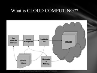
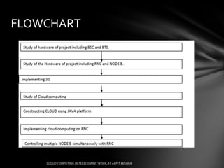
Using cloud computing to integrate multiple NODE B through
RNC in a 3G network


                                              ARPIT MISHRA
                                           MTECH(EXTC)405
      UNDER THE GUIDANCE OF : PROF.RUKHSANA KHAN
What is CLOUD COMPUTING??
Introduction

Node B which had to be configured earlier
through RNC one by one, can be managed
simultaneously with the help of cloud
computing which works on a common server
and, henceforth if one NODE B is configured
then all other NODE B which are connected to
the same RNC via the CLOUD could be
configured simultaneously
• Cloud computing refers to
  – the applications delivered as services over the
    Internet
  – the hardware and systems software in the data
    centers that provide those services.
• The services are referred to as Software as a
  Service (SaaS).and IaaS (Infrastructure as a
  Service) or PaaS (Platform as a Service)
SYSTEM ARCHITECTURE
RNC (Radio Network Controller)


• The Radio Network Controller (or RNC) is a
  governing element in the UMTS radio access network
  (UTRAN) and is responsible for controlling the Node
  Bs that are connected to it.
• The RNC carries out radio resource management,
  some of the mobility management functions and is the
  point where encryption is done before user data is sent
  to and from the mobile.
• The RNC connects to the Circuit Switched Core
  Network through Media Gateway (MGW) and to the
  SGSN (Serving GPRS Support Node) in the Packet
  Switched Core Network.
NODE B
• Node B is a term used in UMTS equivalent to the BTS
  (base transceiver station) description used in GSM.
• It is the hardware that is connected to the mobile
  phone network that communicates directly with
  mobile handsets. In contrast with GSM base stations.
• Node B uses WCDMA/TD-SCDMA as the air
  interface technology.
• As in all cellular systems, such as UMTS and GSM,
  the Node B contains radio frequency transmitter(s) and
  the receiver(s) used to communicate directly with
  mobile devices, which move freely around it.
• In this type of cellular network, the mobile devices
  cannot communicate directly with each other but have
  to communicate with the Node B.
Power Amplifier Unit – HPA
• Amplifies RF signals
• Reports temperature
• Provides overcurrent, over temperature, overpower, and
  over standing wave protections

Duplex Filter Unit – DFL
• Provides transmission/reception combination and
  dividing/splitting functions for RF signals
• Provides transmit/receive RF channel filtering
• Provides the low noise amplifier (LNA) function
• Provides transceiver unit with the LNA alarm reporting
  function
Power Module – RPW
• Power modules can be divided into AC and DC power
  modules, that is, RPW AC/DC. If AC power supply is
  used, the RPW AC is configured. If DC power supply is
  used, the RPW DC is configured. The RPW provides the
  following functions:
• Coverts AC/DC power supply
• Provides the transceiver unit with under voltage,
  overvoltage, and overcurrent alarms
Control Clock & Switch Board (CC)


It has Ethernet switching function and supports the data switching between
service flow and control flow in the system.
• It handles Iub interface protocols (NBAP, SSCOP, and ALCAP).
• It monitors, controls, and maintains base station systems.
• It manages the versions of board software and programmable logic devices
    in the system, and supports local and remote version upgrade.
• It monitors the working condition of the boards in the system.
• It synchronizes external reference clocks.
• It generates and distributes the clock signals required by individual parts
    in the system.
Fiber Switch Board (FS)


Interface introduction:
• Tx0/Rx0 - Tx5/Rx5: It provides the optical interface that
   connects with RRU.
• Board functions.
• It switches baseband I/Q data. It provides the interface
   between BBU and RRU
Site Alarm Board (SA)

• SA Board functions.
• It supports alarm control and speed control of up to nine
  fans.
• It provides signal monitoring and interface lightning
  protection for the shelf at which it is located.
• It provides six input dry contact interfaces and two
  input/output dry contact interfaces.
• It provides eight E1/T1 interfaces.
CLOUD COMPUTING
• a model for enabling convenient, on-demand
  network access to a shared pool of configurable
  computing resources (e.g., networks, servers,
  storage, applications, and services) that can be
  rapidly provisioned and released with minimal
  management effort or service provider interaction.
• Cloud Computing makes computer infrastructure
  and services available "on-need" basis.
Layers
Use of Cloud Computing in Telecom

• All function entities in hierarchical layers of telecom
networks used to run on dedicated servers.
• With cloud computing, these servers can now be
located in the cloud.
• The hierarchical layers of telecom networks will
disappear.
• All functions entities of telecom networks can be
dynamically created, allocated, de-allocated, moved
and removed from virtual machines in the cloud.
• Benefits include
to scale telecom services on demand
to improve reliability and availability
to efficiently use infrastructure
FLOWCHART
CONCLUSION

• Cloud computing is the future trend of the world-wide IT
  industry.
• Telecom networks are evolving quickly to broadband
  wireless IP networks with emergence of LTE/SAE.
• Two aspects of integration of cloud computing and telecom
  networks
   Use of Telecom Networks in Cloud Computing
   Use of Cloud Computing in Telecom Networks
References
1. 3GPP. Technical Specification Group Radio Access Network;
Physical channels and mapping of transport channels onto physical
channels (FDD) (Release 6). 3rd Generation Partnership Project, Dec.
2005. 3GPP TS 25.211 V6.7.0.
2. 3GPP. Technical Specification Group Radio Access Network; Base
Station (BS) radio transmission and reception (FDD) (Release 6). 3rd
Generation Partnership Project, Dec. 2006. 3GPP TS 25.104 V6.14.0.
3. 3GPP. Technical Specification Group Radio Access Network;
Synchronisation in UTRAN Stage 2 (Release 6). 3rd Generation
Partnership Project, Dec. 2006. 3GPP TS 25.402 V6.5.0.
4. 3GPP. Technical Specification Group Radio Access Network;
UTRAN overall description (Release 6). 3rd Generation Partnership
Project, Dec. 2006. 3GPP TS 25.401 V6.9.0.
5. Holma, H., and Toskala, A. WCDMA for UMTS: Radio Access for
Third Generation Mobile Communications, revised ed. John Wiley &
Sons,Ltd., Chichester, West Sussex, England, 2001.
6. Hurtig, P. Private Communication. Ericsson, RBSIoV, Oct. 2006.
.

Cloud computing in telecommunication

  • 1.
    Using cloud computingto integrate multiple NODE B through RNC in a 3G network ARPIT MISHRA MTECH(EXTC)405 UNDER THE GUIDANCE OF : PROF.RUKHSANA KHAN
  • 2.
    What is CLOUDCOMPUTING??
  • 3.
    Introduction Node B whichhad to be configured earlier through RNC one by one, can be managed simultaneously with the help of cloud computing which works on a common server and, henceforth if one NODE B is configured then all other NODE B which are connected to the same RNC via the CLOUD could be configured simultaneously
  • 4.
    • Cloud computingrefers to – the applications delivered as services over the Internet – the hardware and systems software in the data centers that provide those services. • The services are referred to as Software as a Service (SaaS).and IaaS (Infrastructure as a Service) or PaaS (Platform as a Service)
  • 6.
  • 7.
    RNC (Radio NetworkController) • The Radio Network Controller (or RNC) is a governing element in the UMTS radio access network (UTRAN) and is responsible for controlling the Node Bs that are connected to it. • The RNC carries out radio resource management, some of the mobility management functions and is the point where encryption is done before user data is sent to and from the mobile. • The RNC connects to the Circuit Switched Core Network through Media Gateway (MGW) and to the SGSN (Serving GPRS Support Node) in the Packet Switched Core Network.
  • 8.
    NODE B • NodeB is a term used in UMTS equivalent to the BTS (base transceiver station) description used in GSM. • It is the hardware that is connected to the mobile phone network that communicates directly with mobile handsets. In contrast with GSM base stations. • Node B uses WCDMA/TD-SCDMA as the air interface technology. • As in all cellular systems, such as UMTS and GSM, the Node B contains radio frequency transmitter(s) and the receiver(s) used to communicate directly with mobile devices, which move freely around it. • In this type of cellular network, the mobile devices cannot communicate directly with each other but have to communicate with the Node B.
  • 9.
    Power Amplifier Unit– HPA • Amplifies RF signals • Reports temperature • Provides overcurrent, over temperature, overpower, and over standing wave protections Duplex Filter Unit – DFL • Provides transmission/reception combination and dividing/splitting functions for RF signals • Provides transmit/receive RF channel filtering • Provides the low noise amplifier (LNA) function • Provides transceiver unit with the LNA alarm reporting function
  • 10.
    Power Module –RPW • Power modules can be divided into AC and DC power modules, that is, RPW AC/DC. If AC power supply is used, the RPW AC is configured. If DC power supply is used, the RPW DC is configured. The RPW provides the following functions: • Coverts AC/DC power supply • Provides the transceiver unit with under voltage, overvoltage, and overcurrent alarms
  • 11.
    Control Clock &Switch Board (CC) It has Ethernet switching function and supports the data switching between service flow and control flow in the system. • It handles Iub interface protocols (NBAP, SSCOP, and ALCAP). • It monitors, controls, and maintains base station systems. • It manages the versions of board software and programmable logic devices in the system, and supports local and remote version upgrade. • It monitors the working condition of the boards in the system. • It synchronizes external reference clocks. • It generates and distributes the clock signals required by individual parts in the system.
  • 12.
    Fiber Switch Board(FS) Interface introduction: • Tx0/Rx0 - Tx5/Rx5: It provides the optical interface that connects with RRU. • Board functions. • It switches baseband I/Q data. It provides the interface between BBU and RRU
  • 13.
    Site Alarm Board(SA) • SA Board functions. • It supports alarm control and speed control of up to nine fans. • It provides signal monitoring and interface lightning protection for the shelf at which it is located. • It provides six input dry contact interfaces and two input/output dry contact interfaces. • It provides eight E1/T1 interfaces.
  • 14.
    CLOUD COMPUTING • amodel for enabling convenient, on-demand network access to a shared pool of configurable computing resources (e.g., networks, servers, storage, applications, and services) that can be rapidly provisioned and released with minimal management effort or service provider interaction. • Cloud Computing makes computer infrastructure and services available "on-need" basis.
  • 15.
  • 16.
    Use of CloudComputing in Telecom • All function entities in hierarchical layers of telecom networks used to run on dedicated servers. • With cloud computing, these servers can now be located in the cloud. • The hierarchical layers of telecom networks will disappear. • All functions entities of telecom networks can be dynamically created, allocated, de-allocated, moved and removed from virtual machines in the cloud. • Benefits include to scale telecom services on demand to improve reliability and availability to efficiently use infrastructure
  • 17.
  • 18.
    CONCLUSION • Cloud computingis the future trend of the world-wide IT industry. • Telecom networks are evolving quickly to broadband wireless IP networks with emergence of LTE/SAE. • Two aspects of integration of cloud computing and telecom networks Use of Telecom Networks in Cloud Computing Use of Cloud Computing in Telecom Networks
  • 19.
    References 1. 3GPP. TechnicalSpecification Group Radio Access Network; Physical channels and mapping of transport channels onto physical channels (FDD) (Release 6). 3rd Generation Partnership Project, Dec. 2005. 3GPP TS 25.211 V6.7.0. 2. 3GPP. Technical Specification Group Radio Access Network; Base Station (BS) radio transmission and reception (FDD) (Release 6). 3rd Generation Partnership Project, Dec. 2006. 3GPP TS 25.104 V6.14.0. 3. 3GPP. Technical Specification Group Radio Access Network; Synchronisation in UTRAN Stage 2 (Release 6). 3rd Generation Partnership Project, Dec. 2006. 3GPP TS 25.402 V6.5.0. 4. 3GPP. Technical Specification Group Radio Access Network; UTRAN overall description (Release 6). 3rd Generation Partnership Project, Dec. 2006. 3GPP TS 25.401 V6.9.0. 5. Holma, H., and Toskala, A. WCDMA for UMTS: Radio Access for Third Generation Mobile Communications, revised ed. John Wiley & Sons,Ltd., Chichester, West Sussex, England, 2001. 6. Hurtig, P. Private Communication. Ericsson, RBSIoV, Oct. 2006. .