Download to read offline


![WEBENCH
®
Design
Copyright © 2021, Texas Instruments Incorporated 7 ti.com/webench
WEBENCH
®
Design Report TPS63070RNMR : TPS63070RNMR 4.5V-13V to 5.00V @ 1.5A June 22, 2021 23:46:56 GMT-07:00
WEBENCH
®
Assembly
Component Testing
Some published data on components in datasheets such as Capacitor ESR and Inductor DC resistance is based on conservative values that
will guarantee that the components always exceed the specification. For design purposes it is usually better to work with typical values. Since
this data is not always available it is a good practice to measure the Capacitance and ESR values of Cin and Cout, and the inductance and DC
resistance of L1 before assembly of the board. Any large discrepancies in values should be electrically simulated in WEBENCH to check for
instabilities and thermally simulated in WebTHERM to make sure critical temperatures are not exceeded.
Soldering Component to Board
If board assembly is done in house it is best to tack down one terminal of a component on the board then solder the other terminal. For surface
mount parts with large tabs, such as the DPAK, the tab on the back of the package should be pre-tinned with solder, then tacked into place
by one of the pins. To solder the tab town to the board place the iron down on the board while resting against the tab, heating both surfaces
simultaneously. Apply light pressure to the top of the plastic case until the solder flows around the part and the part is flush with the PCB. If the
solder is not flowing around the board you may need a higher wattage iron (generally 25W to 30W is enough).
Initial Startup of Circuit
It is best to initially power up the board by setting the input supply voltage to the lowest operating input voltage 4.5V and set the input supply's
current limit to zero. With the input supply off connect up the input supply to Vin and GND. Connect a digital volt meter and a load if needed
to set the minimum Iout of the design from Vout and GND. Turn on the input supply and slowly turn up the current limit on the input supply.
If the voltage starts to rise on the input supply continue increasing the input supply current limit while watching the output voltage. If the
current increases on the input supply, but the voltage remains near zero, then there may be a short or a component misplaced on the board.
Power down the board and visually inspect for solder bridges and recheck the diode and capacitor polarities. Once the power supply circuit is
operational then more extensive testing may include full load testing, transient load and line tests to compare with simulation results.
Load Testing
The setup is the same as the initial startup, except that an additional digital voltmeter is connected between Vin and GND, a load is connected
between Vout and GND and a current meter is connected in series between Vout and the load. The load must be able to handle at least rated
output power + 50% ( 7.5 watts for this design). Ideally the load is supplied in the form of a variable load test unit. It can also be done in the
form of suitably large power resistors. When using an oscilloscope to measure waveforms on the prototype board, the ground leads of the
oscilloscope probes should be as short as possible and the area of the loop formed by the ground lead should be kept to a minimum. This will
help reduce ground lead inductance and eliminate EMI noise that is not actually present in the circuit.
Design Assistance
1. Master key : B1426EAE683F59EC[v1]
2. TPS63070 Product Folder : http://www.ti.com/product/TPS63070 : contains the data sheet and other resources.](https://image.slidesharecdn.com/wbdesign53-210623070404/85/Circuit-Design-using-TI-7-320.jpg)

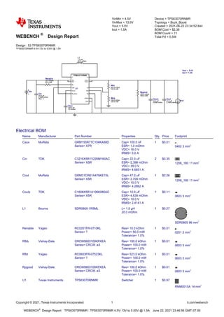
This document provides a design report from WEBENCH for a buck-boost converter using the TPS63070RNMR IC. The design converts an input voltage range of 4.5V to 13V to a regulated 5V output at 1.5A. The report includes performance curves, a bill of materials, and design specifications. It recommends using the TPS63070RNMR with 11 components including capacitors, inductors, and resistors to implement the converter design.


![ceramic-art-and-pottery [Autosaved].pptx](https://cdn.slidesharecdn.com/ss_thumbnails/ceramic-art-and-potteryautosaved-260113113456-35c55ddb-thumbnail.jpg?width=640&height=640&fit=bounds)

