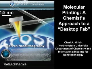
Molecular Printing: A Chemist’s Approach to a “Desktop Fab
•
3 likes•1,512 views

These techniques allow for direct-write nanofabrication with high resolution down to 10 nm. Recent developments in PPL and beam pen lithography provide highly parallel printing over large areas for applications like biological studies. Molecular printing tools are becoming more accessible and may enable desktop nanofabrication.

Recommended
More Related Content
What's hot
What's hot (18)
Viewers also liked
Similar to Molecular Printing: A Chemist’s Approach to a “Desktop Fab
Similar to Molecular Printing: A Chemist’s Approach to a “Desktop Fab (20)
More from The Air Force Office of Scientific Research
More from The Air Force Office of Scientific Research (20)
Recently uploaded
Recently uploaded (20)
Molecular Printing: A Chemist’s Approach to a “Desktop Fab
- 1. Molecular Printing: A Chemist’s Approach to a “Desktop Fab” Chad A. Mirkin Northwestern University Department of Chemistry and International Institute for Nanotechnology
- 2. Modern Printing Tools Revolutionized the World Is It Possible to Create A “Desk Top Fab”? Desk Top Printer Information transfer, the semiconductor industry, the microelectronics revolution, and gene chips It is exceedingly difficult to print with molecules and many materials on the “nanometer scale”
- 3. Dip Pen Nanolithography (DPN) Attributes of DPN: • Direct-write • High resolution: 10 nm line width, ~5 nm spatial resolution • Positive printing • Writing and imaging with same tool • Molecule general • Substrate general • Serial or massively parallel
- 4. The NSCRIPTORTM An Integrated DPN System
- 5. Scanning Probe Lithography: A Dichotomy is Emerging Destructive Constructive Nanografting Delivery of Delivery of DPN Nanoshaving Energy Materials Anodic Oxidation “Millipede”
- 6. 85 nm 12 nm 135 nm 90 nm 100 nm 185 nm Nanogap Electrodes Gold Nanostructures Silver Nanostructures ~45 nm Dip-Pen Nanolithograpy Hard Materials 290 nm 500 nm Sol Gel Materials 4mm 1 mm Nanoparticle Arrays Single-Walled Carbon Silicon Nanostructures Nanotubes
- 7. Combinatorial DPN Templates Small Organic Molecules Polymer resists 4mm Ultrahigh Density DNA Arrays Conducting Polymers Soft Materials Virus Nanoarrays 100 nm 550 nm 550 nm 4 µm Protein Nanostructures Protein Nanoarrays Bio-nanoelectrics
- 8. The Ultimate in High Density Arrays Conventional Microarray Robotic Spotter (1 Dot/200x200 mm2) Feedback Controlled Lithography (100,000,000,000 Dot/200x200 mm2) Low Resolution DPN (50,000 Dot/200x200 mm2) High Resolution DPN (100,000,000 Dot/200x200 mm2) Biological Nanoarrays: • More than just miniaturization with higher density • New opportunities for biodetection and studying biorecognition • Templates for guiding the assembly of larger building blocks • Open up the opportunity to study multivalency and surface cooperativity
- 9. Can DPN be Used To Generate Multicomponent Templates that are Used to Recognize and Larger Biological structures and Organisms? 120 nm ~20 µm ~15 µm 8.5 nm Protein Virus Spores Living Cells (Human IgG) (HIV) (Anthrax)
- 10. DPN-Generated Biological Nanoarrays 4 mm 5 mm Single Virus Nanoarrays Multicomponent DNA Phospholipid Arrays Nanoarrays 80 mm 4 mm Cell Arrays on Nanopatterned Substrates • Sub 50 nm many mm resolution Multicomponent Protein • Large Array Patterning Nanoarrays • Multi-component Patterning Capabilities • Reconstructing the extracellular matrix at the nm scale
- 11. DPN Generated Positive Photomasks Au Etch Au Au Etch DPN Cr Cr Etch ODT Quartz Cr Photomask Device Characterization Replicated Au Electrode Empty electrode 0.8 PPY nanotube PPY nanotube with UV 0.4 Current (nA) 0.0 -0.4 -0.8 -1.0 -0.5 0.0 0.5 1.0 Voltage (V) Jang et al, Small, 2009, 5, 1850
- 12. DPN Spot Size Is Independent of Applied Force Molecular diffusion from point source is independent of applied force between tip and surface.
- 13. NanoPrint Array II: 55,000 tips ~ 1 cm2 Pen fabrication yield >99% (preliminary) 20×90 µm In collaboration 1.5 mm with J. Fragala, NanoInk
- 14. 40×40 dots at 400 nm pitch ~88 million features in ~20 min 5 µm 400 nm 100 mm 100 nm
- 15. Development of Cantilever-Free Scanning Probe Lithography Cantilever-Based Cantilever-Free DPN 1D Multipen 2D 55,000 Pen Polymer Pen Scanning Probe Block Hard-Tip, Soft (1999) Cantilever Array Cantilever Array Lithography Copolymer LithographySpring Lithography (2000) (2006) (2008) (2010) (2011) Key Advance 1: Key Advance 2: Key Advance 3: Deposition of Use an elastomeric Move the “spring” materials pyramid on a solid from the tip to a rather than backing for cantilever- polymer backing Thermal DPN Beam Pen energy free printing layer (2004) Lithography (2010) Giam, et al. Angew. Chem. 2011, 50, 7482.
- 16. PDMS Pen Array Fabrication Huo, F et al. Science. 2008, 321, 1658.
- 17. 11 Million Pen Polymer Array A B C D (A)11 million pen array. (B) SEM image of the polymer pen array. (C) An etched gold pattern on a 4 inch Si wafer. (D) Optical microscope image of gold patterns. Huo, F et al. Science. 2008, 321, 1658.
- 18. Polymer Pen Lithography (PPL) High Resolution High Throughput Mask-free Nanofabrication Huo, F et al. Science. 2008, 321, 1658.
- 19. Printing Circuit Designs on Multiple Scales 100 circuits in 1 cm2 with 500 nm and 100 µm features 100 µm 500 nm 500 nm 100 μm 500 nm Huo, F et al. Science. 2008, 321, 1658.
- 20. Feature Size Control Time Dependence Z-Piezo Dependence Feature Edge Length vs Dwell Time Feature Size vs Z-Piezo Extension Huo, F. et al. Science. 2008, 321, 1658. Liao. et al. Small, 2010, 6, 1082.
- 21. Tip-Height Sensing: Force Dependence F1 < F2 Z F NELbottom Ltop H L feature Ltop F NELtop Force Dependent Pattern Feature Edge Length vs Force Liao. et al. Small, 2010, 6, 1082.
- 22. Leveling the Pen Array by Force Tilted PPL Array Z Height of the Tilted Pen Array θ: tilting angle to the y axis φ: tilting angle to the x axis Z ( N x , N y , , ) Z0 DN x sin( ) DN y sin( ) M1, M2 and M3: θ = 0.07° Motors holding the pen array φ = 0.06 ° Liao. et al. Nano Lett. 2010, 10, 1335.
- 23. Leveling the Pen Array by Force Calculated Ftotal vs θ and φ Experimental Ftotal vs θ and φ F / mN Ftotal / mN total θ/ ° φ/ ° ELbottom Ltop • At the perfect leveling position, the total force F ( N x , N y , , ) Z ( N x , N y , , ) reaches its global maximum H • For each fixed θ, the force reaches its local maximum when φ=0 and vice verse Ftotal ( , ) F (N x , N y , , ) • Around the perfect leveling position, the Nx N y gradient is very large Liao. et al. Nano Lett. 2010, 10, 1335.
- 24. Leveled Patterns 0o θ = 0° 2.54 ± 0.05 mm –0.01o θ = –0.01° 4.68 ± 0.89 mm +0.01o θ = +0.01° 5.33 ± 1.03 mm Liao. et al. Nano Lett. 2010, 10, 1335.
- 25. Multiplexed Protein Patterning by PPL Inkjet print multiple Pattern multiplexed Feature size control protein into inkwells protein arrays inkwells Inkwells with different Multiplexed patterning fluorescent proteins of protein arrays Zheng, Z et al. Angew Chem. 2009, 48, 7626 .
- 26. Combinatorial Libraries Generated by Tilting PPL Array PPL array substrate High contact force Printed Area Low contact force
- 27. Large area patterns Why PPL? • Patterns over large areas for studying thousands to millions of cells • Ability to produce combinatorial arrays with different feature sizes (micro to nanoscale) • Ability to level the PPL array and produce homogeneous features over large areas Feature width = 1.34 μm Feature width = 475 nm Feature pitch = 2 μm Feature pitch = 2 μm
- 28. MSC Differentiation Studied by PPL- Generated Combinatorial Arrays 100 μm CBFα1 actin DAPI
- 29. Massively Parallel Hybrid Silicon Pen Nanolithography 10 μm Z-piezo Glue Ultra-High Resolution High Throughput Mask-free Nanofabrication 1 mm Easy Alignment
- 30. Pen Tip Array 500 μm Si tip 22 nm Soft backing layer 1 um 100 μm
- 31. Massively Parallel Hybrid Silicon Pen Writing Before contact with the surface Different light reflection In contact with the surface
- 32. Feature Size Control Time Dependence Z-Piezo Dependence Z=12 μm 6 μm 10 μm 4 μm 5 μm 8 μm Feature Edge Length vs Dwell Time Feature Size vs Z-Piezo Extension 1200 1200 Dot diameter (nm) 1000 1000 Diameter (nm) 800 800 600 600 400 400 200 200 0 0 0 1 2 3 4 4 6 8 10 12 1/2 Contact time (s ) Z-piezo Extension (um)
- 33. Feature Size Resolution i ii 5 μm 5 μm ii i iv iii 10 μm iii 5 μm 5 μm iv Average Feature Size = 42 nm
- 34. Block Copolymer Assisted TBN
- 35. Block Copolymer (BCP) Patterns BCP Deposition (Height) BCP Deposition (Phase) 100 nm 90 ° 5 µm 5 µm 100 nm AFM Height Profile 50 Height (nm) 30 10 -10 2 µm 0 2 4 6 8 10 Distance (µm) Cai et al, submitted
- 36. Single Nanoparticles Formed by Block Copolymer TBN SEM of AuNP Array TEM and Diffraction of AuNP • The spatial resolution is controlled by the piezo-controlled tip position • Fourier transform analysis confirms uniformity of the AuNP pattern • Sub-10 nm single crystal Au NPs are formed by the BCP method • TEM and Diffraction patterns confirm single crystal composition of the nanostructures Cai et al, submitted
- 37. Nanoparticle Size Control Cai et al, submitted
- 38. Large-Scale Patterning 1 µm Au NPs on SiO2 Cai et al, submitted
- 39. Particle Size Consistency Au NPs on SiO2 Cai et al, submitted
- 40. Growth Trajectories: Cryo-TEM Movie of Ripening Process 2 nm
- 41. Formation of Single Nanoparticles Observed -120 degrees C, ~ 1 min frame interval FOR OFFICIAL USE ONLY – Not Cleared for Open Release
- 42. Two Mechanisms are Occurring • Coalescence observed for particles closer than ~ 5 nm • Ostwald ripening observed for particles further apart -120 degrees C, ~ 5 min frame interval FOR OFFICIAL USE ONLY – Not Cleared for Open Release
- 43. Beam Pen Lithography (BPL) Fabricating a Beam Pen Array BPL array 200 nm Aperture 1 μm Aperture 2 μm Aperture 100 μm 2 μm 2 μm 20 μm Huo et al, submitted
- 44. Beam Pen Lithography (BPL) BPL Scheme Au dot arrays by BPL 10 x 10 dot array Patterning 150 μm Arbitrary patterns by BPL Chicago Skyline Develop 20 μm Evaporation + liftoff 100 μm Huo et al, submitted
- 45. Mask-Assisted BPL Mask assisted BPL Patterns of “NU” with selected pens • Drawbacks: – Photo mask is needed – Can not in-situ address the pens Huo et al, submitted
- 46. Development of Molecular Printing Tools Parallel Printing Woodblock Printing Printing Press (China ~200) (Gutenberg, 1439) Movable Type μ-Contact Printing Beam Pen Polymer Pen (Bi Sheng, ~1041-1048) (Whitesides, 1993) Lithography (PPL) Lithography (BPL) (2008) (2010) Serial Writing Hard Tip, Soft Spring Scanning Probe Block Dip-Pen Lithography Copolymer Lithography Quill Pen Nanolithography (DPN) (2010) (2010) (~2000 BC) (Mirkin, 1999) Ball-Point (Loud, 1888)
- 47. A Step Towards “Desktop Nanofabrication”: Take Home Messages • DPN and PPL are workhorse molecular printing research tools, which allow researchers to rapidly prototype and study molecule-based structures. • The barrier to scanning probe parallelization is crumbling; PPL, BPL, and SPBCL open the door for low cost and rapid nanofabrication procedures. • The techniques are poised to make the transition from primarily research tools to high throughput synthesis and fabrication tools, especially in the life sciences.
- 48. World Use of Dip Pen Nanolithography Australia: Swinburne U. – Nicolau Canada: U.of Alberta – Buriak Japan: China: NAIST– Ushijima Chinese Acad. of Sci .(Lanzhou) – Li Nagoya U.– Ichimiya CIST – Hua Korea: MIT – Stellacci Peking U. – J. Liu , Y Li. Samsung Electronics, Co. NASA Langley – Watkins Chinese Acad. of Sci. (Shanghai )- Zhang Seoul Nat. U. – Nam, Naval Research – Byers, Chinese Acad. of Sci.(Beijing) –Z. Liu S. Hong Whitman, Sheehan Xi’an Jiaotong U. – Zhang, Liu Pusan Nati. U. – Il Kim N. Carolina State U. – Southwest U. – Tang Sungkyunkwan U. – HJ Kim Narayan Columbia: Korea U. –Ahn Northwestern U.– Dravid, Servico Nacional de Aprendizaje (SENA) Yonsei U.–H. Jung United States: Liu, Mirkin, Wolinsky, France: Netherlands: Air Force Research – Espinosa CNRS France – Joachim U. of Twente– Reinhoudt, Naik, Stone NYU – Braunschweig UMass Lowell - Mead Germany: Velders Albany NanoTech – Kossow Ohio State U.– Lee UC Davis – G. Liu Inst. für NanoTechnologie, Singapore: Brookhaven – Ocko Penn State U.– Weiss UCSB – Hu Forschungszentrum India: Nanyang Tech–Liu , Huo, Cal.Tech.– Collier Portland State University- U. of Chicago – Karlsruhe– Fuchs CEERI – Kumar Zhang , Boey, Huang Cal. State – Schwartz Yan, La Rosa Mrkisch Ludwig Inst.– Bein Jawaharlal Nehru Cen. for Spain: Corning Inc Purdue U. – Ivanesivic U. of Florida – Ren Max Planck Inst. – Bastiaen Adv. Sci. Research– Rao Inst. Català– Maspoch, Science & Tech Rensselaer Poly.– Nalamasu UIUC – C. Liu, Great Britain: Indian Inst. Sci. – Brar Garcia, Martinez Duke U. – J. Lui, Chilkoti Sandia NL – Hsu U. of Maryland – Gomez U. of Cambridge –Rayment Israel: Parc Cientific–Samitier George Mason U. – Espina Stanford U. – Bao U. of N. Carolina – Imperial College – Cass Hebrew U. – Willner Taiwan: Georgia NanoFab – Lewis Stevens IT – Libera Zauscher U. of Ulster Italy: Acad. Sinica–Tao Harvard U. – Lieber Texas A & M – Banerjee, U. of Washington – U. of Strathclyde –Graham Politec. di Milano – Levi Nat. Chiao Tung U.– Sheu Lawrence Berkeley – Batteas Ginger Hong Kong: U. degli Studi di Milano Nat. Taiwan U.– Lin De Yoreo Texas Tech – Vaughn, Weeks Washington Tech Xu Bicocca – Sassella Schmidt Scientific Loyola U. – Holz Tufts U. – Kaplan Center – Allen
- 50. Mirkin Group
- 51. Acknowledgements Collaborators Prof. Chang Liu (NU) Prof. Harald Fuchs (Münster, Germany) Dr. Steven Lenhert (Münster, Germany) Prof. Mark Ratner (NU), Prof. Michael Bedzyk (NU) Prof. Vinayak Dravid (NU), Dr. Morley Stone (WP AFRL) Prof. Milan Mrksich (University of Chicago) Prof. George Schatz (NU), Dr. Rajesh Naik (WP AFRL) Prof. Hua Zhang (Nanyang Technical University, Singapore) Joe Fragala (NanoInk) Funding AFOSR, ARO DARPA (TBN Program), HSARPA, NSF, ONR, NIH, DOD NSSEF Fellowship