Downloaded 32 times

![Network Layer 4-44
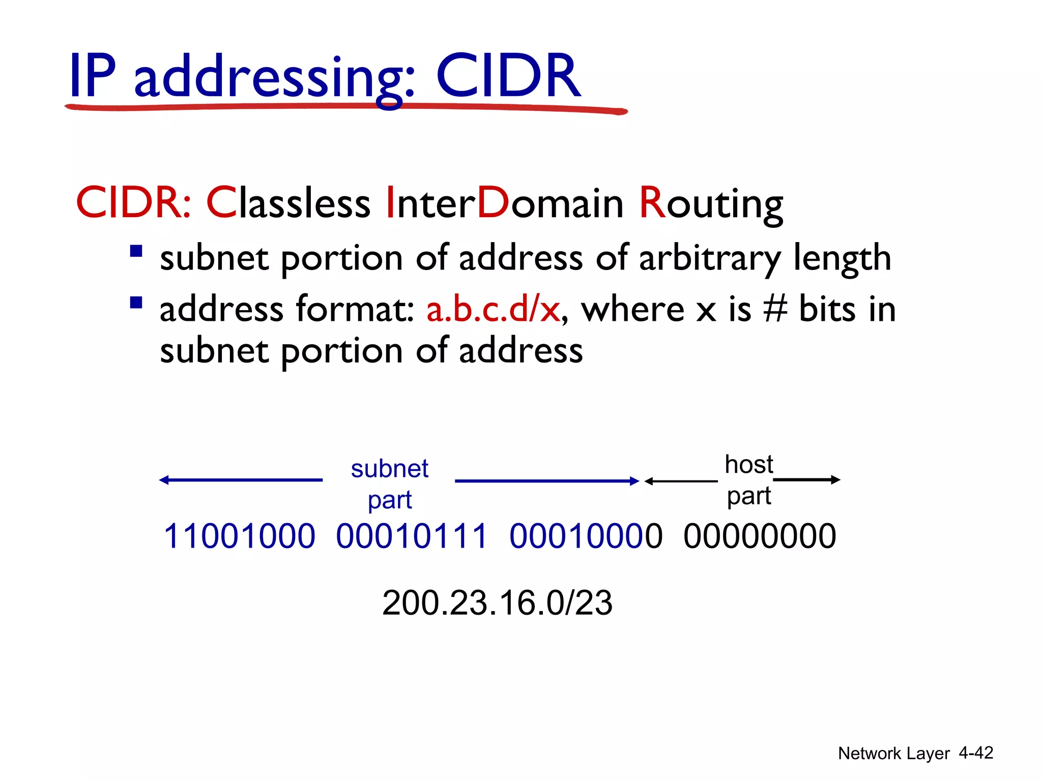
DHCP: Dynamic Host Configuration Protocol
goal: allow host to dynamically obtain its IP address from network
server when it joins network
can renew its lease on address in use
allows reuse of addresses (only hold address while
connected/“on”)
support for mobile users who want to join network (more
shortly)
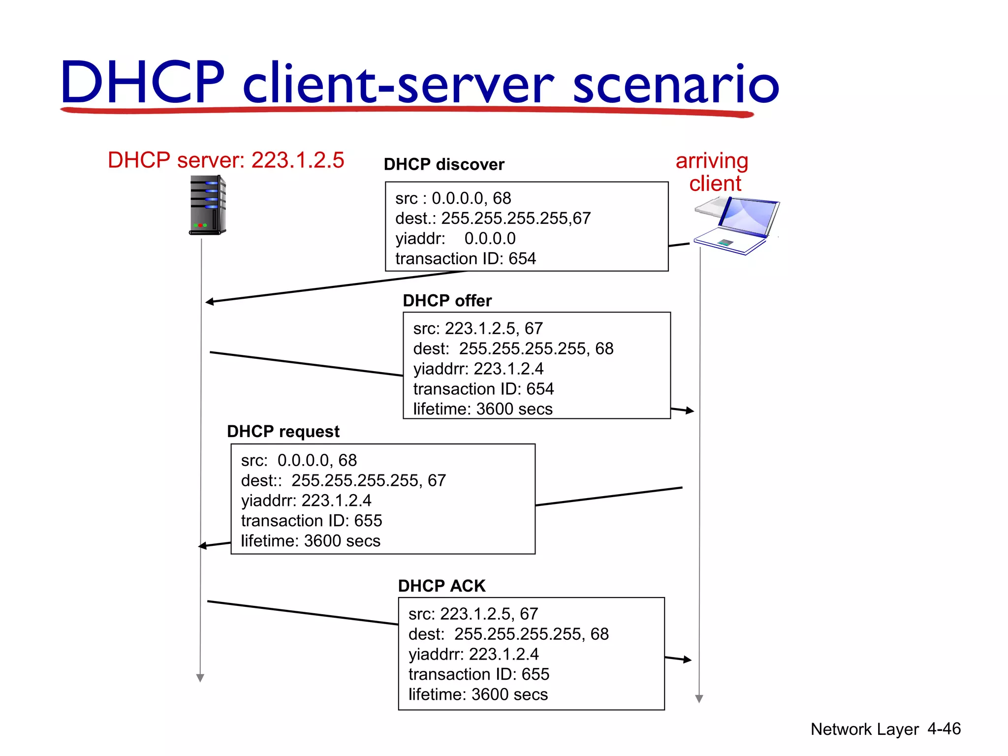
DHCP overview:
host broadcasts “DHCP discover” msg [optional]
DHCP server responds with “DHCP offer” msg [optional]
host requests IP address: “DHCP request” msg
DHCP server sends address: “DHCP ack” msg](https://image.slidesharecdn.com/chapter4l4-170212062017/75/Chapter4-l4-44-2048.jpg)

![Network Layer 4-87
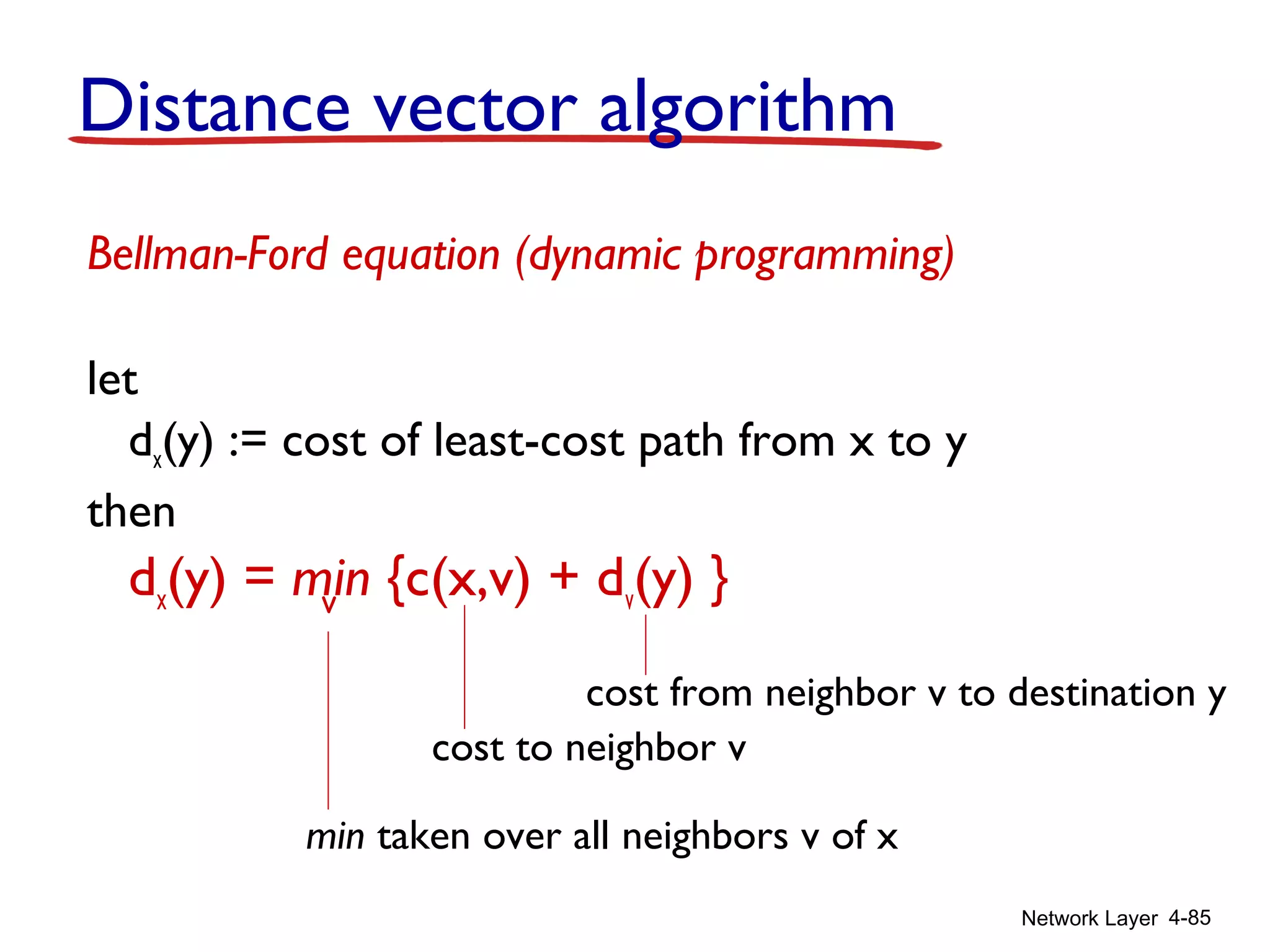
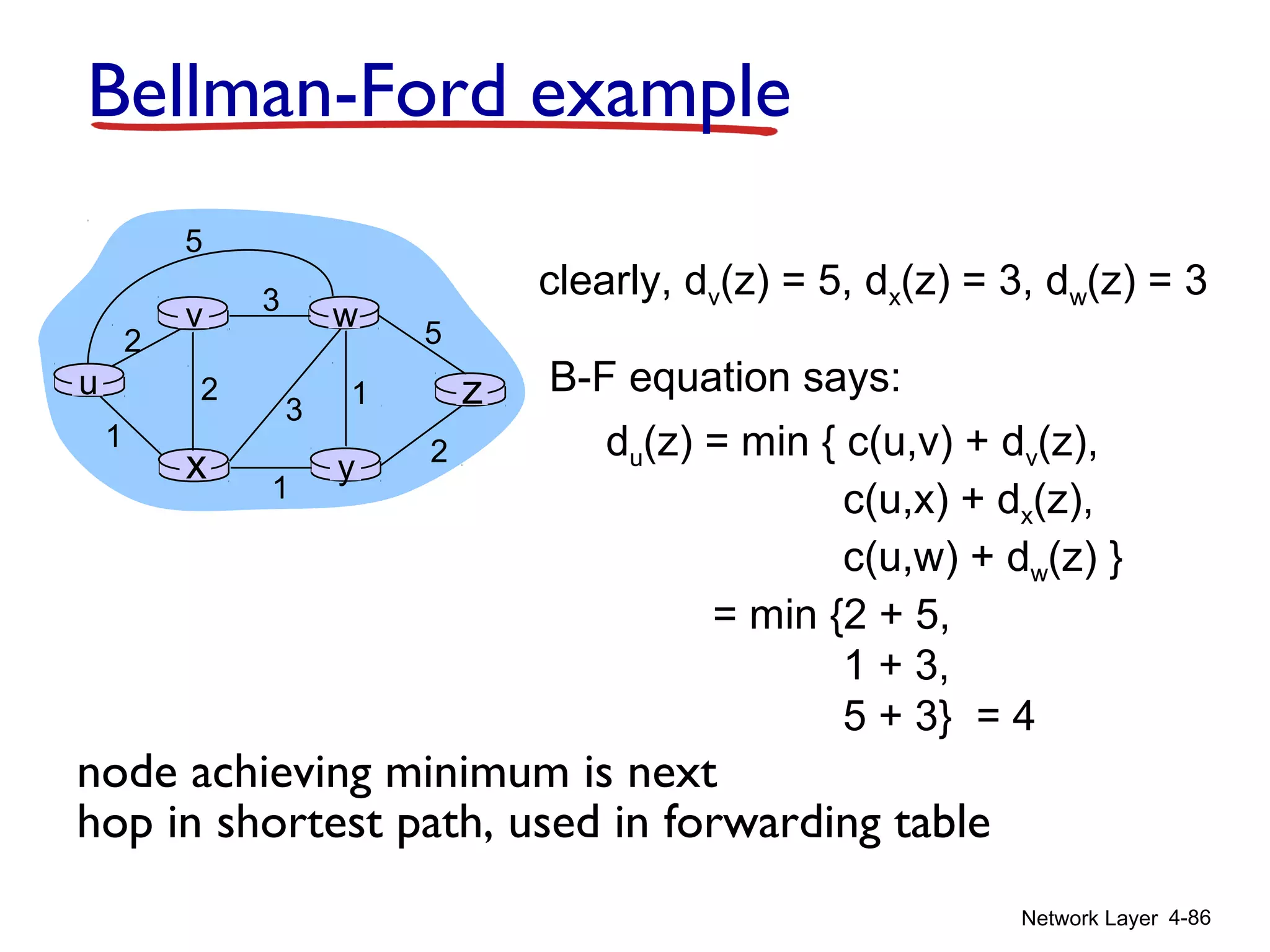
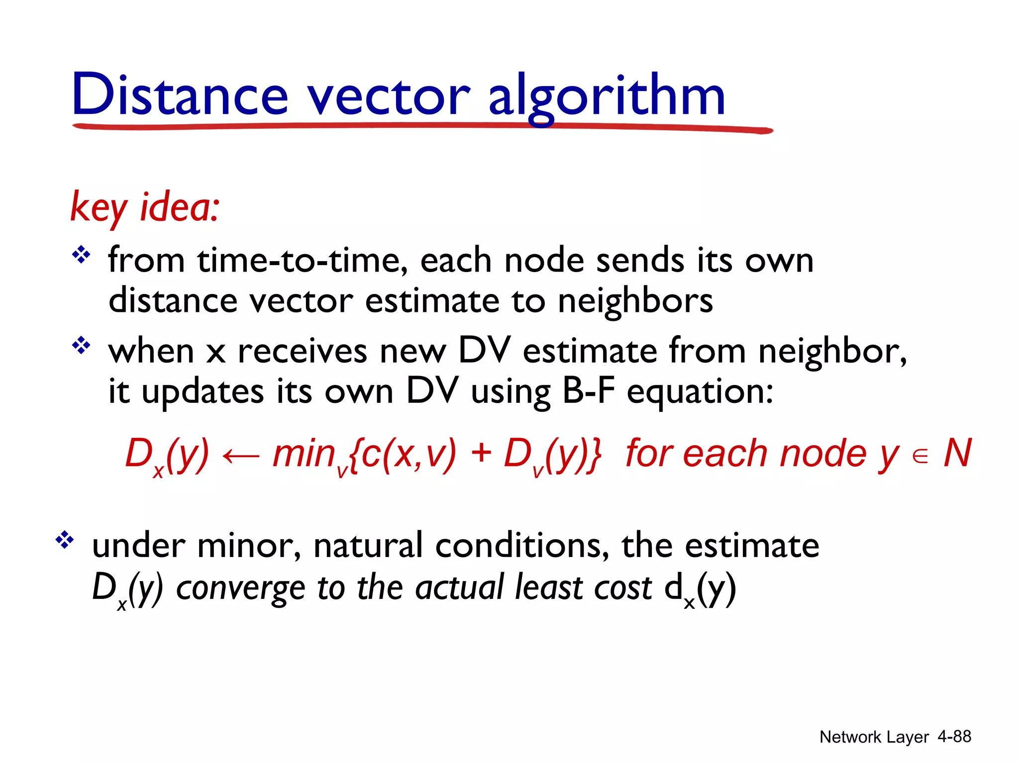
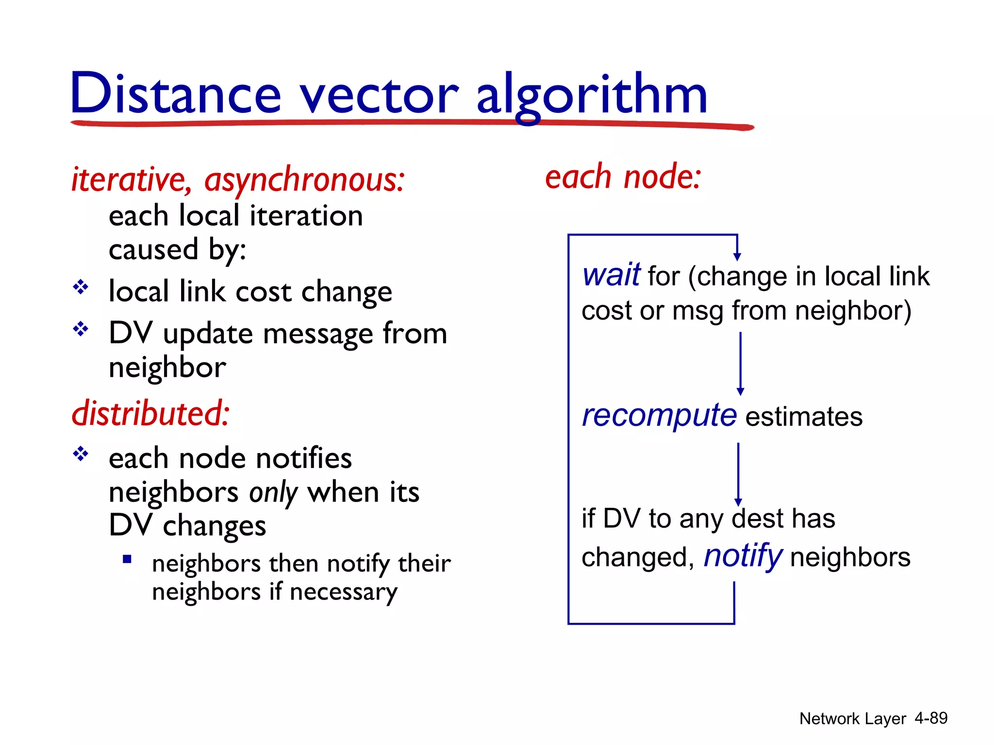
Distance vector algorithm
Dx(y) = estimate of least cost from x to y
x maintains distance vector Dx = [Dx(y): y є N ]
node x:
knows cost to each neighbor v: c(x,v)
maintains its neighbors’ distance vectors. For
each neighbor v, x maintains
Dv = [Dv(y): y є N ]](https://image.slidesharecdn.com/chapter4l4-170212062017/75/Chapter4-l4-87-2048.jpg)


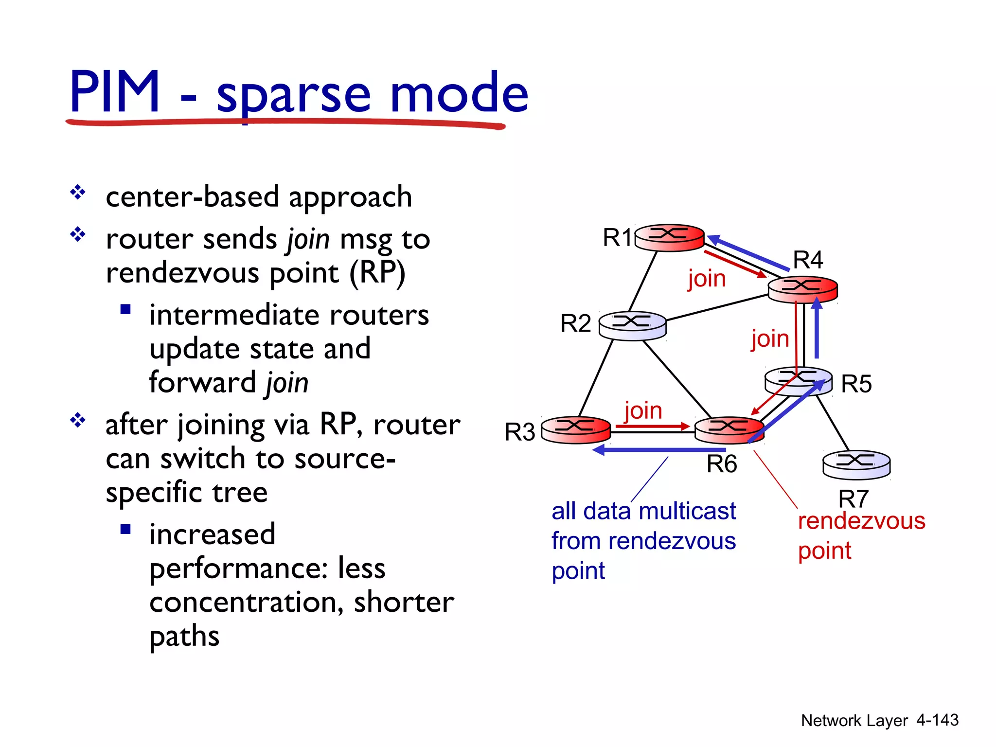
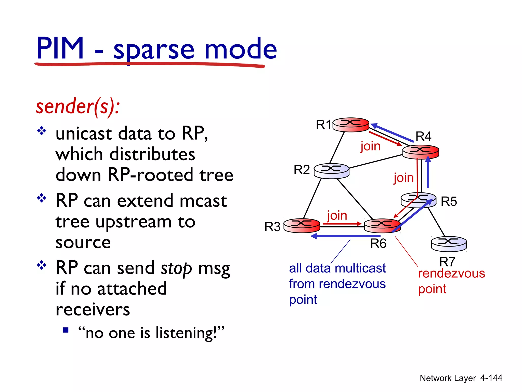
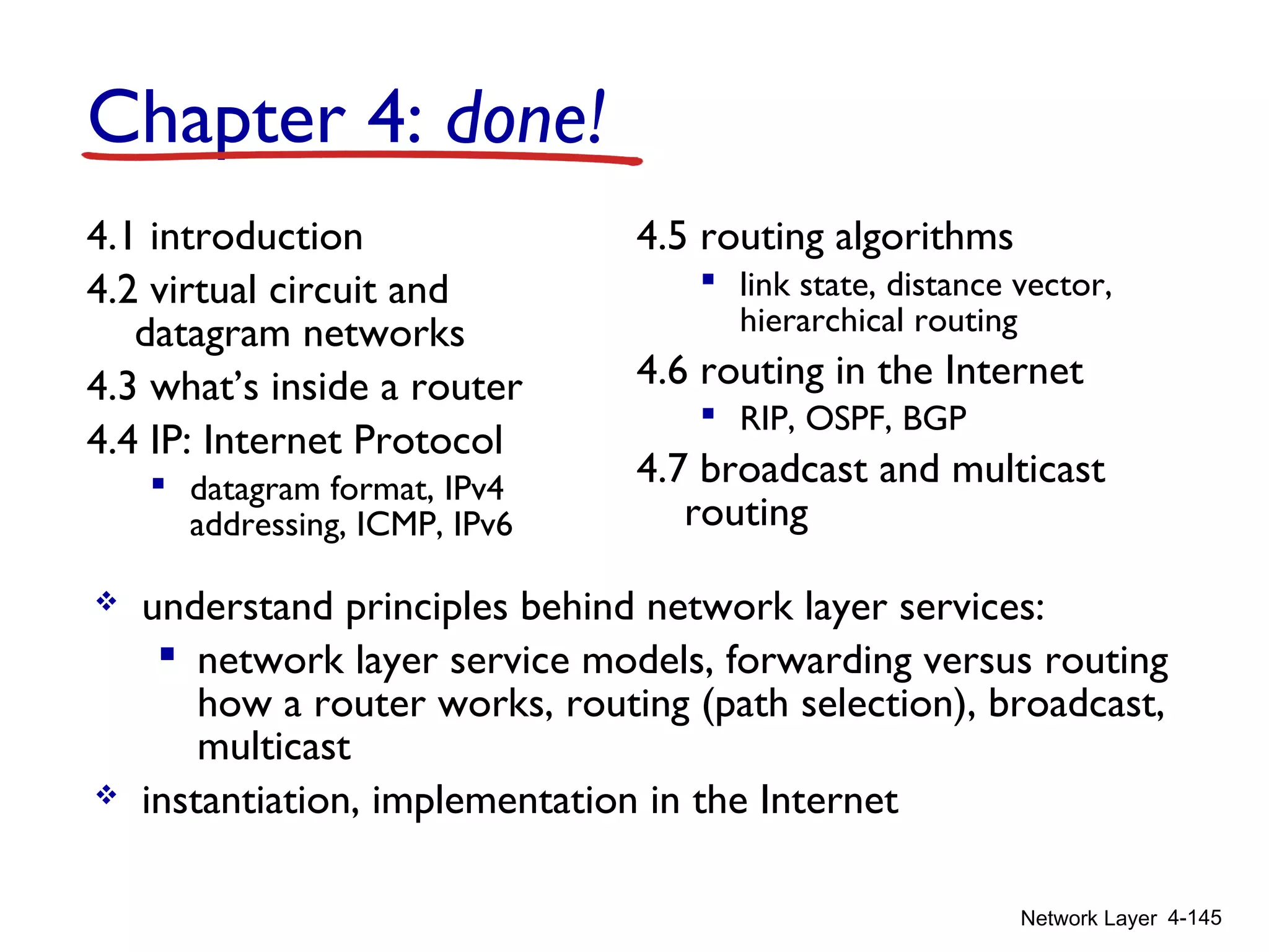

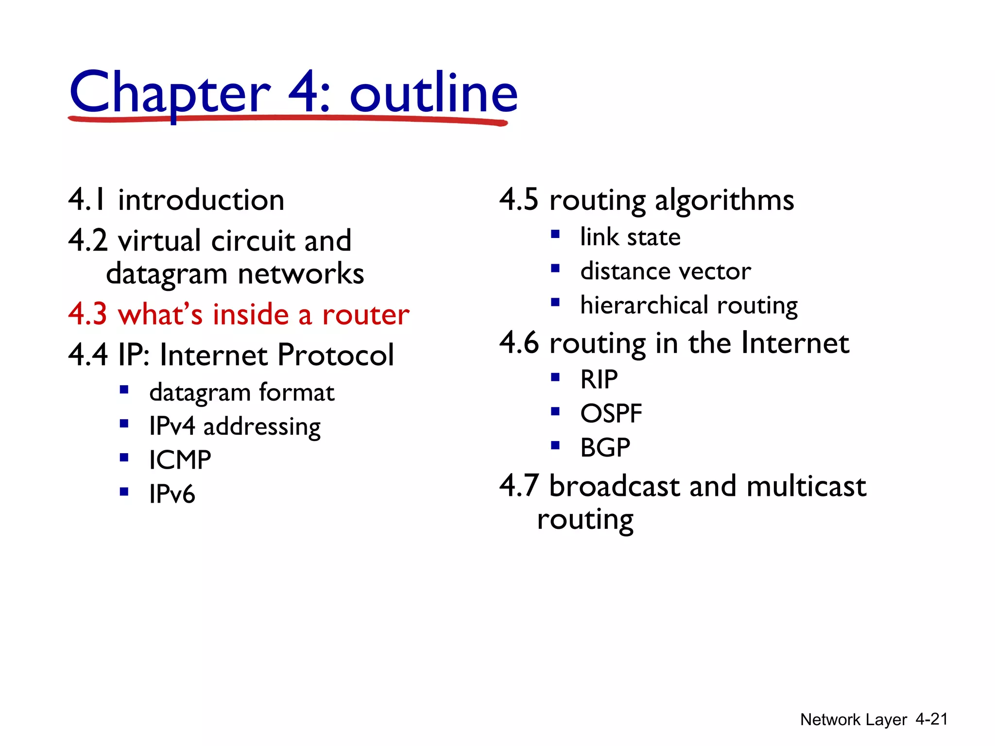
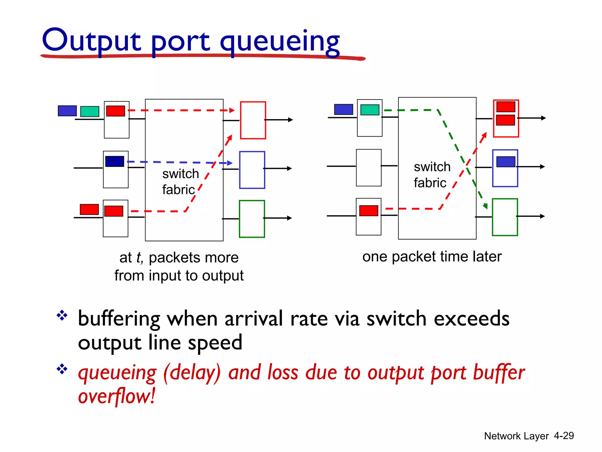
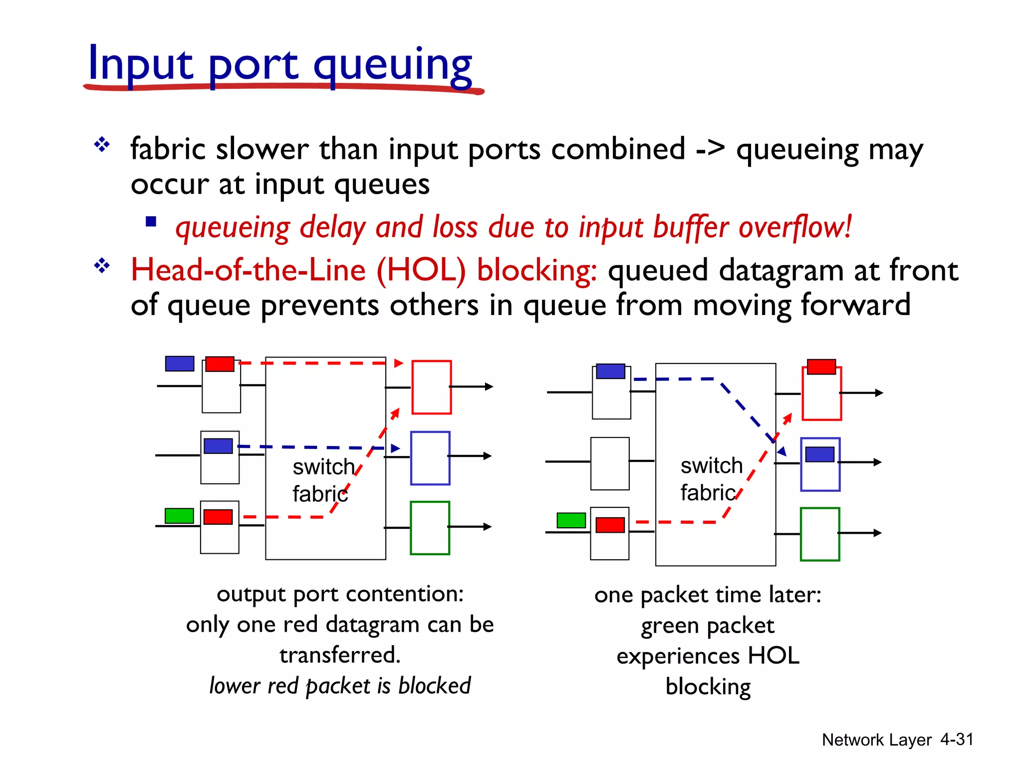
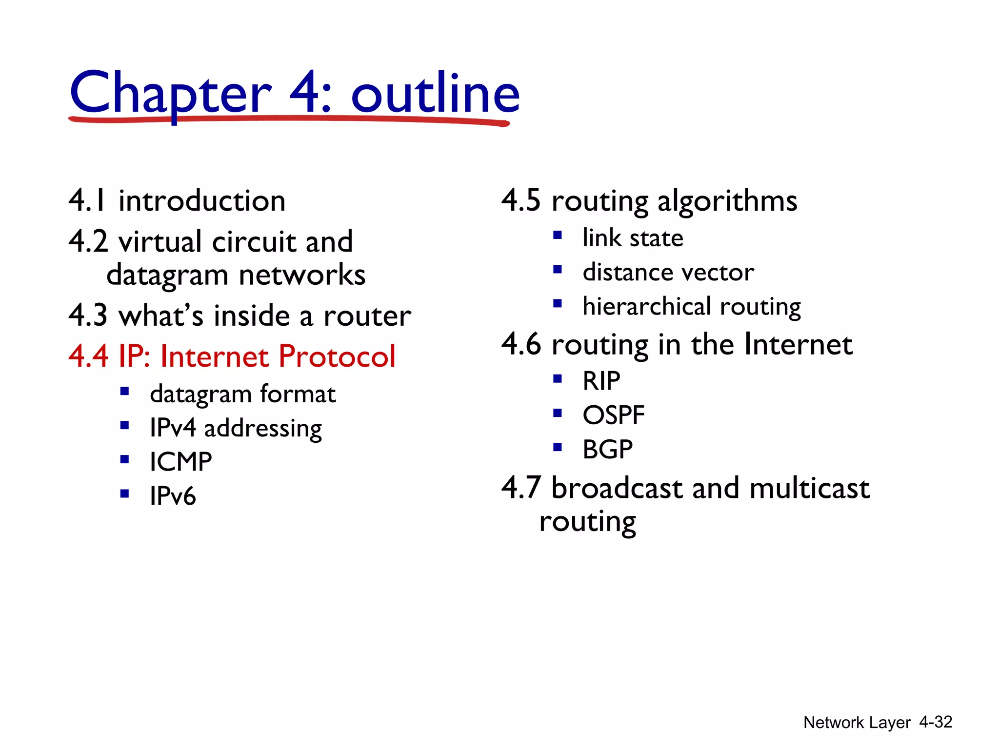
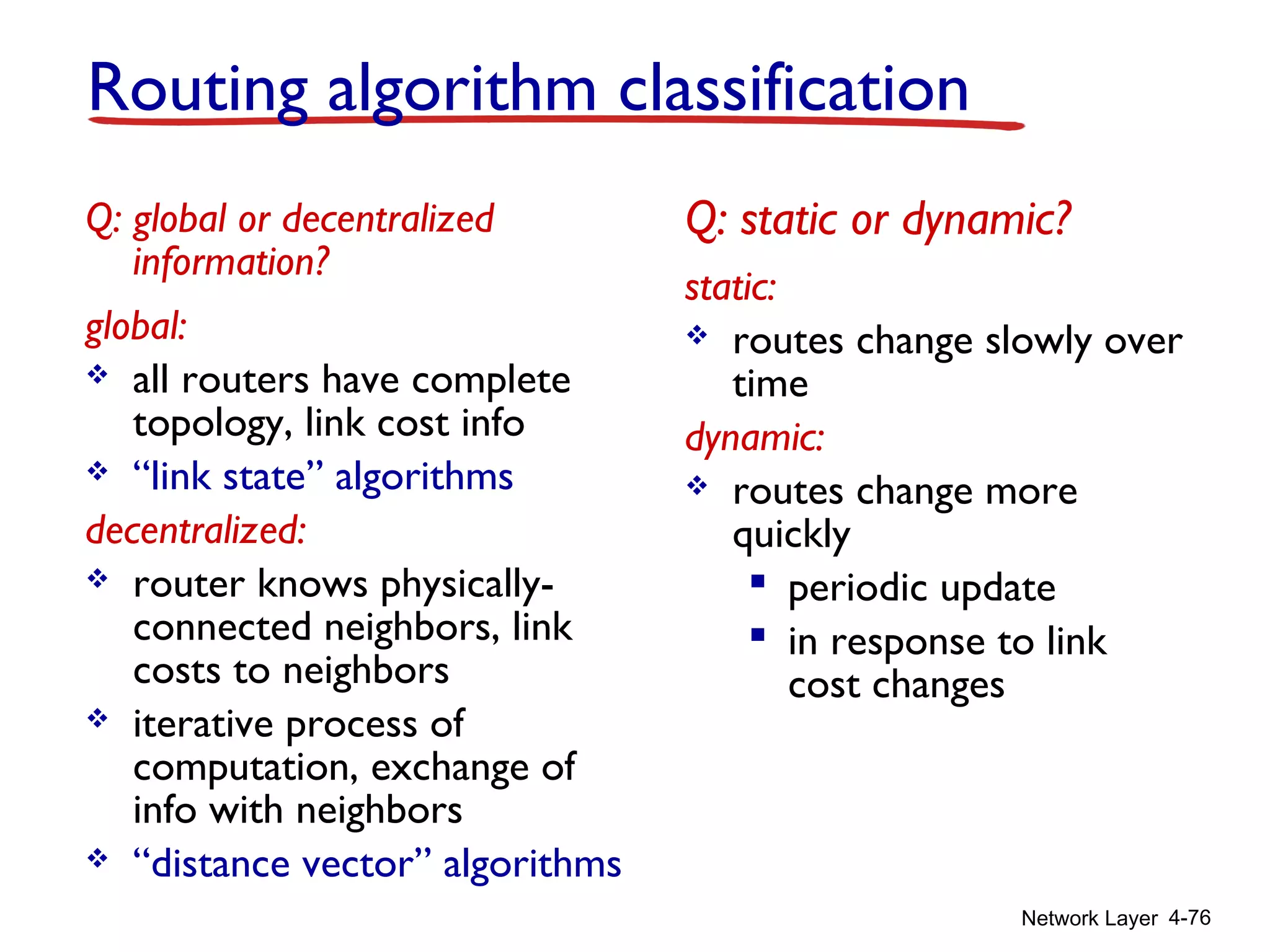
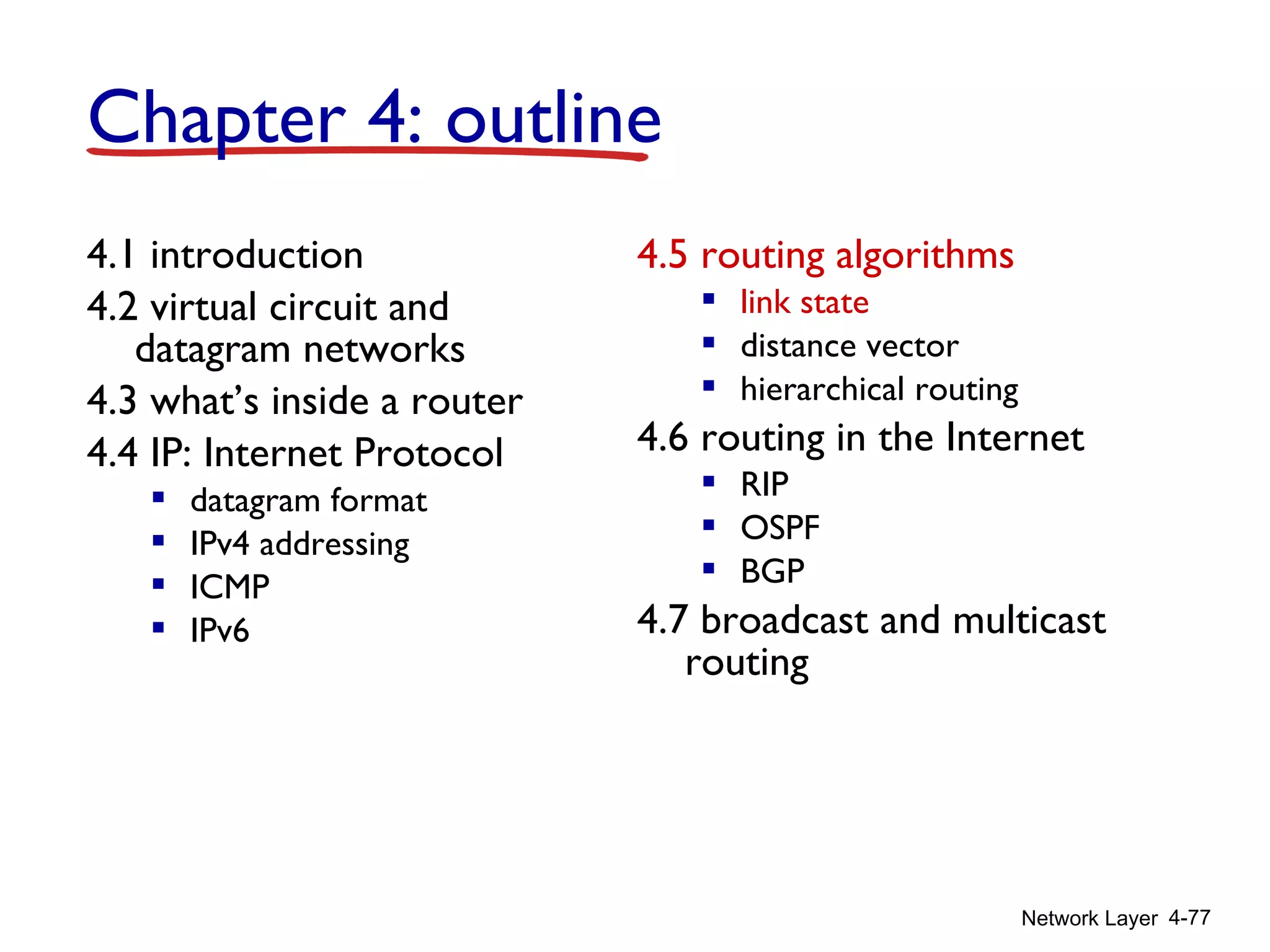
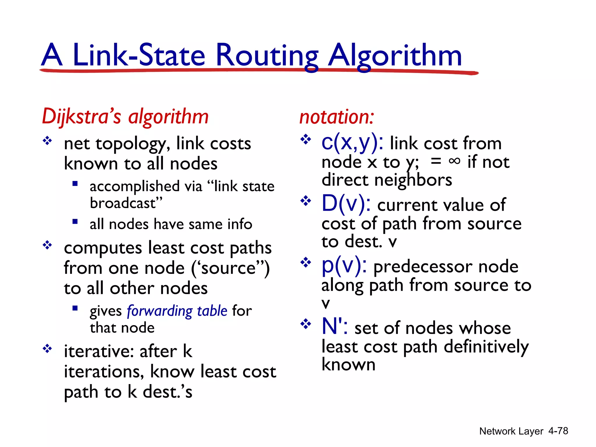
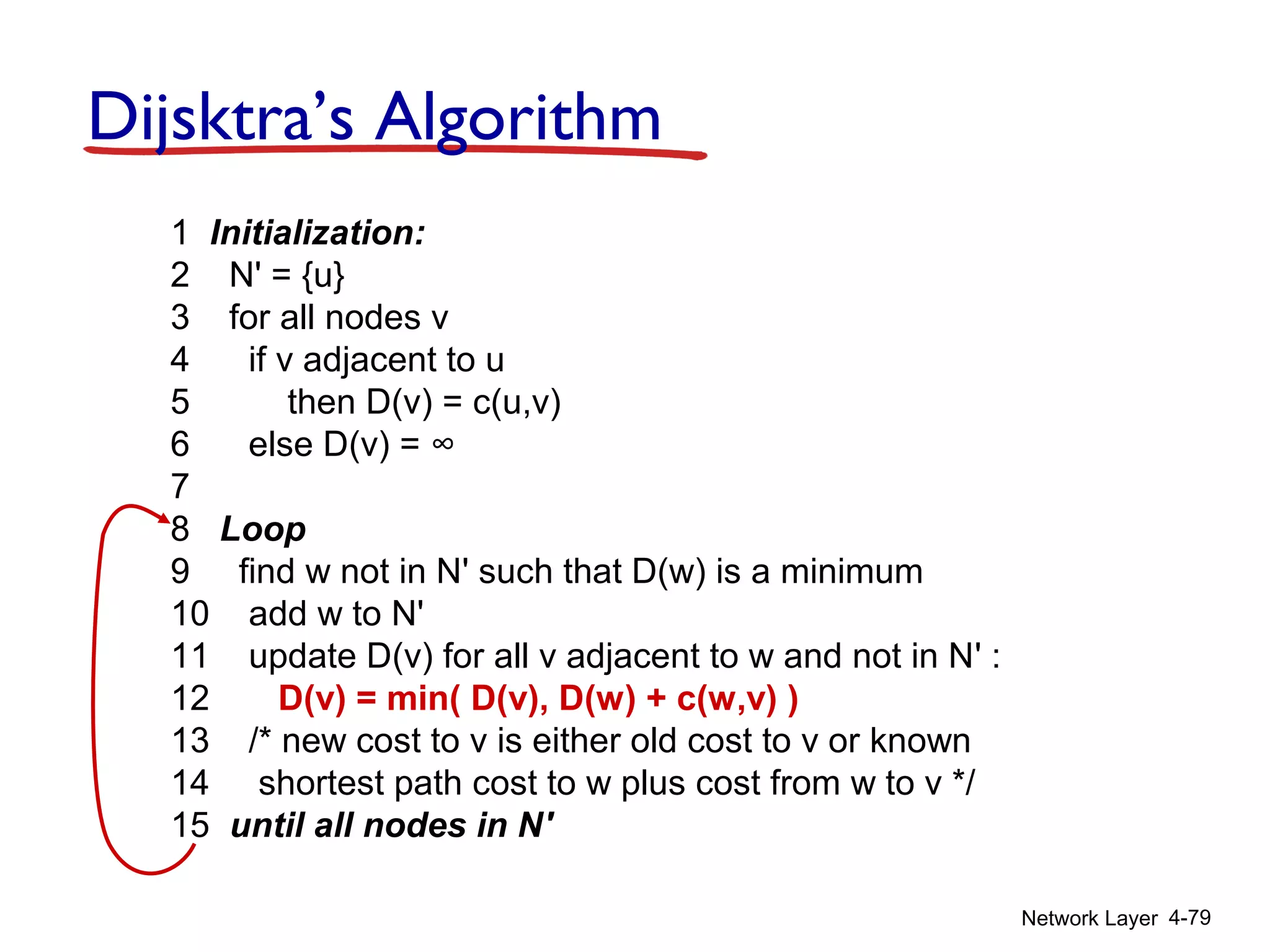
The document outlines Chapter 4 of a networking textbook. Chapter 4 covers the network layer, including network layer services, how routers work, routing algorithms, and implementations in the Internet. The key topics covered are virtual circuit versus datagram networks, the functions of routers including forwarding and routing, and routing algorithms like link state and distance vector.