Downloaded 126 times
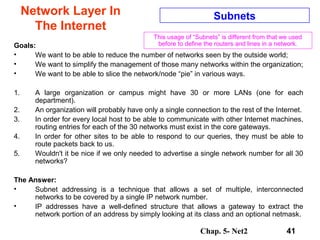
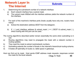
![Chap. 5- Net2 63
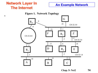
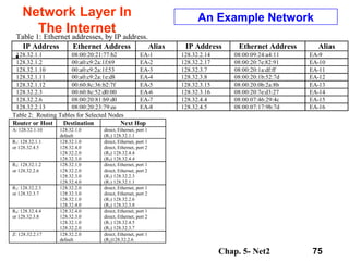
Network Layer In
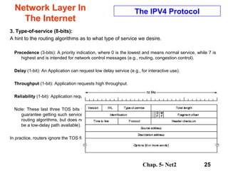
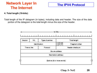
The Internet
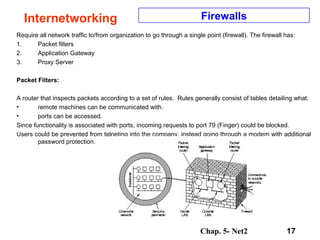
Interior Gateway Protocol - OSPF
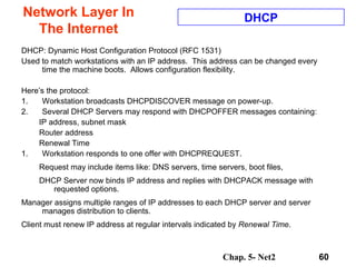
OSPF supports three kinds of networks:
1. Point to point lines between two routers.
2. Multiaccess networks with broadcasting (LANs).
3. Multiaccess networks without broadcasting
(packet switched WANs ).
[Here a multiaccess network is one that has multiple
routers, each of which can talk to all the other
routers. This is a common LAN/WAN property.]
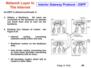
As OSPF is defined, it:
1. Divides an Autonomous System into “areas”.
An area is a network or set of contiguous
networks. All routers in an AS do not need to
be in an Area.
2. Uses a link-state algorithm within an area.
Thus distances are calculated based on length,
or other properties. See Figure 5.52](https://image.slidesharecdn.com/chapter05-net2-150316104404-conversion-gate01/85/Network-Layer-63-320.jpg)

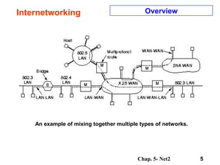
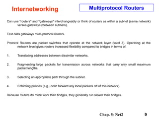
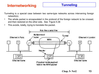
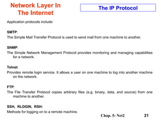
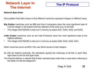
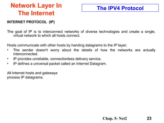
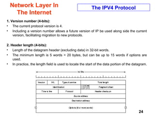
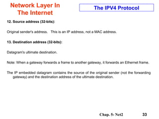
Chapter 5 discusses the network layer, which focuses on routing packets from source to destination through various networks. It covers design issues, routing algorithms, congestion control, and the challenges of internetworking different network technologies. Key concepts include routers, gateways, fragmentation, and the Internet Protocol (IP), which allows for connectionless transmission across diverse network types.


![How Big Brands are Taking Your Traffic in Alberta [Data Inside].pptx](https://cdn.slidesharecdn.com/ss_thumbnails/howbigbrandsaretakingyourtrafficinalbertadatainside-260123180142-42d276f3-thumbnail.jpg?width=640&height=640&fit=bounds)


