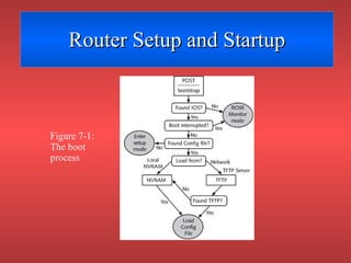
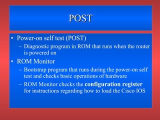
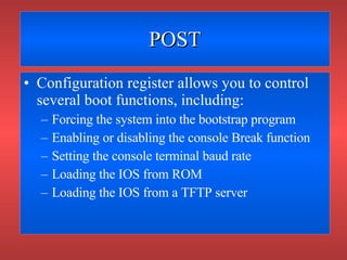
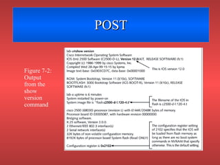
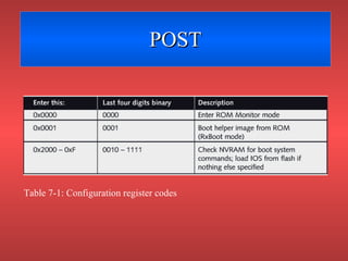
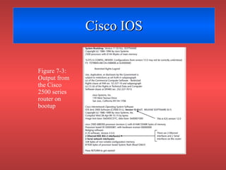
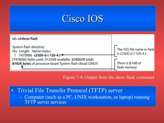
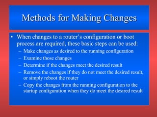
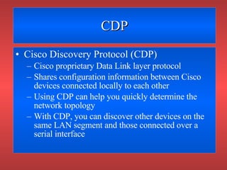
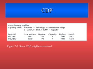
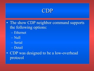
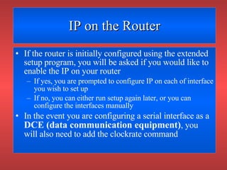
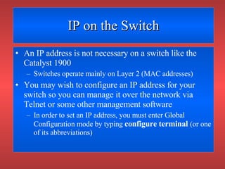
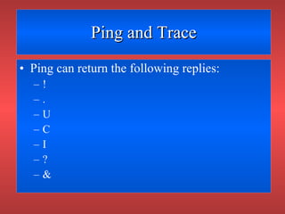
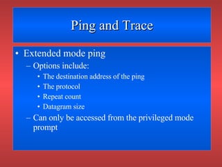
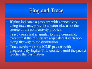
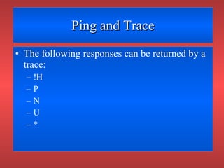
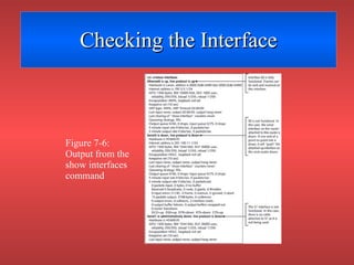
CHAPTER SEVEN Router Startup and Configuration
Objectives Understand router setup and startup Describe and use the Cisco Discovery Protocol Understand configuration management commands for Cisco routers and the 1900 series switch Configure IP on the Cisco router and the 1900 series switch Troubleshoot router connectivity problems
Router Setup and Startup A router follows a specific boot process, but processes can vary In general, the boot process follows these steps: Test hardware (POST) Load bootstrap Locate and load Cisco IOS Locate and load router configuration file
Router Setup and Startup Figure 7-1: The boot process
POST Power-on self test (POST) Diagnostic program in ROM that runs when the router is powered on ROM Monitor Bootstrap program that runs during the power-on self test and checks basic operations of hardware ROM Monitor checks the  configuration register  for instructions regarding how to load the Cisco IOS
POST Configuration register allows you to control several boot functions, including: Forcing the system into the bootstrap program Enabling or disabling the console Break function Setting the console terminal baud rate Loading the IOS from ROM Loading the IOS from a TFTP server
POST Figure 7-2: Output from the show version command
POST Table 7-1: Configuration register codes
Monitor Mode You can set the router to enter ROM Monitor mode during the boot process by modifying the configuration register ROM Monitor mode Router mode in which you can configure the router manually You must provide each command in the correct syntax in order to configure the router
Cisco IOS Figure 7-3: Output from the Cisco 2500 series router on bootup
Cisco IOS Trivial File Transfer Protocol (TFTP) server Computer (such as a PC, UNIX workstation, or laptop) running TFTP server services Figure 7-4: Output from the show flash command
Cisco IOS Cisco routers support the following fallback options for loading the IOS: If the IOS is configured to load from a TFTP server, but that server cannot be located, the IOS is loaded from flash memory If the IOS cannot be found in flash or on a TFTP server, a minimal version of the IOS is loaded from ROM
Booting from TFTP You can force the router to load its IOS from a TFTP server by putting boot system commands into the configuration file Global configuration mode Router mode that allows you to manipulate most of the router’s generic settings Prompt for global configuration mode is router(config)#
Upgrading the IOS Before loading a flash file to a router, use the show flash command to ensure there is enough free memory to load the new Cisco IOS software The system will tell you how much memory is used and how much is free You may have to erase the existing flash memory before writing onto it due to space limitations
RXBoot Mode Another configuration mode that you can enter when: The changes to your system make it impossible to boot from the flash memory You cannot locate a valid IOS image The prompt from RXBoot mode is the hostname of your router followed by “boot” in parentheses
Cisco Catalyst 1900 IOS and Configuration Management To upgrade or restore IOS via TFTP, the command syntax is  copy tftp://tftp_server_address/IOS_file/ opcode The opcode command tells the device to load the file into flash memory To backup configuration settings for a Catalyst 1900 switch, copy contents of NVRAM to a TFTP server The command syntax is  copy nvram tftp://tftp_server_address/config_file_name
Router Configuration Files Table 7-2: Important router copy commands
Router Configuration Files Table 7-2 (cont.): Important router copy commands
Methods for Making Changes When changes to a router’s configuration or boot process are required, these basic steps can be used: Make changes as desired to the running configuration Examine those changes Determine if the changes meet the desired result Remove the changes if they do not meet the desired result, or simply reboot the router Copy the changes from the running configuration to the startup configuration when they do meet the desired result
CDP Cisco Discovery Protocol (CDP) Cisco proprietary Data Link layer protocol Shares configuration information between Cisco devices connected locally to each other Using CDP can help you quickly determine the network topology With CDP, you can discover other devices on the same LAN segment and those connected over a serial interface
CDP Figure 7-5: Show CDP neighbor command
CDP The show CDP neighbor command supports the following options: Ethernet Null Serial Detail CDP was designed to be a low-overhead protocol
IP on the Router If the router is initially configured using the extended setup program, you will be asked if you would like to enable the IP on your router If yes, you are prompted to configure IP on each of interface you wish to set up If no, you can either run setup again later, or you can configure the interfaces manually In the event you are configuring a serial interface as a  DCE (data communication equipment) , you will also need to add the clockrate command
IP on the Switch An IP address is not necessary on a switch like the Catalyst 1900 Switches operate mainly on Layer 2 (MAC addresses) You may wish to configure an IP address for your switch so you can manage it over the network via Telnet or some other management software In order to set an IP address, you must enter Global Configuration mode by typing  configure terminal   (or one of its abbreviations)
IP Connectivity Table 7-3: Testing connectivity by layer
Telnet Utility that connects at the highest layer of the OSI model Provides remote access to other devices Cisco routers allow telnet connections via their virtual terminal ports If you can establish telnet connectivity to a router, you have established that it is available on the network and that you have connectivity at all layers
IP Host Names When telnetting to a remote router or host, the IP address of the host must follow the telnet command Rather than using IP addresses, it is easier to refer to a remote host or router using a name Sometimes, you cannot gain connectivity because the host name that you are trying to connect with is entered in a table incorrectly Using a name server provides name resolution from one location, making a table configuration on each device unnecessary
Ping and Trace If you can’t get connectivity at the Application layer, try connectivity at the Internetwork layer Ping and trace verify connectivity at the Internetwork layer Both use ICMP messages to verify the destination host is reachable, and if not, give possible reasons for the problem Ping sends a packet to the destination and waits for a response By default, the ping utility with Cisco routers is configured to send five packets to the target
Ping and Trace Ping can return the following replies: ! . U C I ? &
Ping and Trace Extended mode ping Options include: The destination address of the ping The protocol Repeat count Datagram size Can only be accessed from the privileged mode prompt
Ping and Trace If ping indicates a problem with connectivity, using trace may provide a better clue as to the source of the connectivity problem Trace command is similar to ping command, except that the replies are requested at each hop along the way to the destination Trace sends multiple ICMP packets with progressively higher TTL counters until the packet reaches the destination
Ping and Trace The following responses can be returned by a trace: !H P N U *
IP Route If you cannot get connectivity using ping or trace, you should check your routing table You can issue the show ip route command from the enable mode prompt This command shows the routing table Typically, routing tables are dynamically created when routing protocols are configured on the router
Checking the Interface On of the biggest mistakes made when troubleshooting is not checking the interfaces on the router If the interfaces are down, packets cannot be delivered Router interfaces go down for a variety of reasons including: Incorrect IP configuration Cable problems
Checking the Interface Keepalive frames Data frames sent between two hosts to ensure that the connection between those hosts remains open Different types of interfaces can show different types of reports For example, a Token Ring interface reports down when there is no electrical carrier signal present
Checking the Interface Figure 7-6: Output from the show interfaces command
Clear Counters Routers keep detailed statistics regarding the data passing across its interfaces Before using the show interface command, you may want to clear the existing interface information You can clear these statistics ( counters ) on the interface by using the clear interface or clear counters command
Debug Debug command One of the most powerful tools you can use to obtain information from your router Only available from privileged EXEC mode Has numerous subcommands that allow you to troubleshoot particular protocols Allows you to check for specific types of traffic on the wire
Debug Figure 7-7: Debug all command output
Chapter Summary When the router boots, it follows a set routine If the Cisco IOS is set to load from a TFTP server, but the TFTP server cannot be located, then the IOS will boot from flash memory If the IOS cannot be found in flash memory or on the TFTP server, a limited version will boot from ROM If the Cisco IOS is set to load a configuration file from a TFTP server, but the file or server is not available, the configuration file will be loaded from NVRAM
Chapter Summary CDP is proprietary to Cisco devices Devices share information about their interface configurations and connections to other devices IP configuration on Cisco switches is similar When you configure an address for a router interface, you must be in interface configuration mode When you configure an IP address for a Catalyst 1900 switch, you need only be in global configuration mode
Chapter Summary You can verify router connectivity to other systems by using telnet to determine if there is Application layer connectivity If you cannot get connectivity at the Application layer, try trace and ping On of the most important troubleshooting commands is the show interface command

Chapter 07

  • 1.
    CHAPTER SEVEN RouterStartup and Configuration
  • 2.
    Objectives Understand routersetup and startup Describe and use the Cisco Discovery Protocol Understand configuration management commands for Cisco routers and the 1900 series switch Configure IP on the Cisco router and the 1900 series switch Troubleshoot router connectivity problems
  • 3.
    Router Setup andStartup A router follows a specific boot process, but processes can vary In general, the boot process follows these steps: Test hardware (POST) Load bootstrap Locate and load Cisco IOS Locate and load router configuration file
  • 4.
    Router Setup andStartup Figure 7-1: The boot process
  • 5.
    POST Power-on selftest (POST) Diagnostic program in ROM that runs when the router is powered on ROM Monitor Bootstrap program that runs during the power-on self test and checks basic operations of hardware ROM Monitor checks the configuration register for instructions regarding how to load the Cisco IOS
  • 6.
    POST Configuration registerallows you to control several boot functions, including: Forcing the system into the bootstrap program Enabling or disabling the console Break function Setting the console terminal baud rate Loading the IOS from ROM Loading the IOS from a TFTP server
  • 7.
    POST Figure 7-2:Output from the show version command
  • 8.
    POST Table 7-1:Configuration register codes
  • 9.
    Monitor Mode Youcan set the router to enter ROM Monitor mode during the boot process by modifying the configuration register ROM Monitor mode Router mode in which you can configure the router manually You must provide each command in the correct syntax in order to configure the router
  • 10.
    Cisco IOS Figure7-3: Output from the Cisco 2500 series router on bootup
  • 11.
    Cisco IOS TrivialFile Transfer Protocol (TFTP) server Computer (such as a PC, UNIX workstation, or laptop) running TFTP server services Figure 7-4: Output from the show flash command
  • 12.
    Cisco IOS Ciscorouters support the following fallback options for loading the IOS: If the IOS is configured to load from a TFTP server, but that server cannot be located, the IOS is loaded from flash memory If the IOS cannot be found in flash or on a TFTP server, a minimal version of the IOS is loaded from ROM
  • 13.
    Booting from TFTPYou can force the router to load its IOS from a TFTP server by putting boot system commands into the configuration file Global configuration mode Router mode that allows you to manipulate most of the router’s generic settings Prompt for global configuration mode is router(config)#
  • 14.
    Upgrading the IOSBefore loading a flash file to a router, use the show flash command to ensure there is enough free memory to load the new Cisco IOS software The system will tell you how much memory is used and how much is free You may have to erase the existing flash memory before writing onto it due to space limitations
  • 15.
    RXBoot Mode Anotherconfiguration mode that you can enter when: The changes to your system make it impossible to boot from the flash memory You cannot locate a valid IOS image The prompt from RXBoot mode is the hostname of your router followed by “boot” in parentheses
  • 16.
    Cisco Catalyst 1900IOS and Configuration Management To upgrade or restore IOS via TFTP, the command syntax is copy tftp://tftp_server_address/IOS_file/ opcode The opcode command tells the device to load the file into flash memory To backup configuration settings for a Catalyst 1900 switch, copy contents of NVRAM to a TFTP server The command syntax is copy nvram tftp://tftp_server_address/config_file_name
  • 17.
    Router Configuration FilesTable 7-2: Important router copy commands
  • 18.
    Router Configuration FilesTable 7-2 (cont.): Important router copy commands
  • 19.
    Methods for MakingChanges When changes to a router’s configuration or boot process are required, these basic steps can be used: Make changes as desired to the running configuration Examine those changes Determine if the changes meet the desired result Remove the changes if they do not meet the desired result, or simply reboot the router Copy the changes from the running configuration to the startup configuration when they do meet the desired result
  • 20.
    CDP Cisco DiscoveryProtocol (CDP) Cisco proprietary Data Link layer protocol Shares configuration information between Cisco devices connected locally to each other Using CDP can help you quickly determine the network topology With CDP, you can discover other devices on the same LAN segment and those connected over a serial interface
  • 21.
    CDP Figure 7-5:Show CDP neighbor command
  • 22.
    CDP The showCDP neighbor command supports the following options: Ethernet Null Serial Detail CDP was designed to be a low-overhead protocol
  • 23.
    IP on theRouter If the router is initially configured using the extended setup program, you will be asked if you would like to enable the IP on your router If yes, you are prompted to configure IP on each of interface you wish to set up If no, you can either run setup again later, or you can configure the interfaces manually In the event you are configuring a serial interface as a DCE (data communication equipment) , you will also need to add the clockrate command
  • 24.
    IP on theSwitch An IP address is not necessary on a switch like the Catalyst 1900 Switches operate mainly on Layer 2 (MAC addresses) You may wish to configure an IP address for your switch so you can manage it over the network via Telnet or some other management software In order to set an IP address, you must enter Global Configuration mode by typing configure terminal (or one of its abbreviations)
  • 25.
    IP Connectivity Table7-3: Testing connectivity by layer
  • 26.
    Telnet Utility thatconnects at the highest layer of the OSI model Provides remote access to other devices Cisco routers allow telnet connections via their virtual terminal ports If you can establish telnet connectivity to a router, you have established that it is available on the network and that you have connectivity at all layers
  • 27.
    IP Host NamesWhen telnetting to a remote router or host, the IP address of the host must follow the telnet command Rather than using IP addresses, it is easier to refer to a remote host or router using a name Sometimes, you cannot gain connectivity because the host name that you are trying to connect with is entered in a table incorrectly Using a name server provides name resolution from one location, making a table configuration on each device unnecessary
  • 28.
    Ping and TraceIf you can’t get connectivity at the Application layer, try connectivity at the Internetwork layer Ping and trace verify connectivity at the Internetwork layer Both use ICMP messages to verify the destination host is reachable, and if not, give possible reasons for the problem Ping sends a packet to the destination and waits for a response By default, the ping utility with Cisco routers is configured to send five packets to the target
  • 29.
    Ping and TracePing can return the following replies: ! . U C I ? &
  • 30.
    Ping and TraceExtended mode ping Options include: The destination address of the ping The protocol Repeat count Datagram size Can only be accessed from the privileged mode prompt
  • 31.
    Ping and TraceIf ping indicates a problem with connectivity, using trace may provide a better clue as to the source of the connectivity problem Trace command is similar to ping command, except that the replies are requested at each hop along the way to the destination Trace sends multiple ICMP packets with progressively higher TTL counters until the packet reaches the destination
  • 32.
    Ping and TraceThe following responses can be returned by a trace: !H P N U *
  • 33.
    IP Route Ifyou cannot get connectivity using ping or trace, you should check your routing table You can issue the show ip route command from the enable mode prompt This command shows the routing table Typically, routing tables are dynamically created when routing protocols are configured on the router
  • 34.
    Checking the InterfaceOn of the biggest mistakes made when troubleshooting is not checking the interfaces on the router If the interfaces are down, packets cannot be delivered Router interfaces go down for a variety of reasons including: Incorrect IP configuration Cable problems
  • 35.
    Checking the InterfaceKeepalive frames Data frames sent between two hosts to ensure that the connection between those hosts remains open Different types of interfaces can show different types of reports For example, a Token Ring interface reports down when there is no electrical carrier signal present
  • 36.
    Checking the InterfaceFigure 7-6: Output from the show interfaces command
  • 37.
    Clear Counters Routerskeep detailed statistics regarding the data passing across its interfaces Before using the show interface command, you may want to clear the existing interface information You can clear these statistics ( counters ) on the interface by using the clear interface or clear counters command
  • 38.
    Debug Debug commandOne of the most powerful tools you can use to obtain information from your router Only available from privileged EXEC mode Has numerous subcommands that allow you to troubleshoot particular protocols Allows you to check for specific types of traffic on the wire
  • 39.
    Debug Figure 7-7:Debug all command output
  • 40.
    Chapter Summary Whenthe router boots, it follows a set routine If the Cisco IOS is set to load from a TFTP server, but the TFTP server cannot be located, then the IOS will boot from flash memory If the IOS cannot be found in flash memory or on the TFTP server, a limited version will boot from ROM If the Cisco IOS is set to load a configuration file from a TFTP server, but the file or server is not available, the configuration file will be loaded from NVRAM
  • 41.
    Chapter Summary CDPis proprietary to Cisco devices Devices share information about their interface configurations and connections to other devices IP configuration on Cisco switches is similar When you configure an address for a router interface, you must be in interface configuration mode When you configure an IP address for a Catalyst 1900 switch, you need only be in global configuration mode
  • 42.
    Chapter Summary Youcan verify router connectivity to other systems by using telnet to determine if there is Application layer connectivity If you cannot get connectivity at the Application layer, try trace and ping On of the most important troubleshooting commands is the show interface command