This document summarizes a CFD analysis of a tee-configured mixing pipe. The analysis varied the velocity of inlet 1 while keeping inlet 2 velocity fixed. It found that increasing inlet 1 velocity by 50% to 3.75 m/s produced the most homogeneous temperature distribution at the outlet. Visualizations of the temperature and velocity fields helped explain the mixing mechanisms and showed improved penetration of the cold stream into the hot stream with the higher inlet 1 velocity, enhancing mixing. The analysis also identified locations of maximum thermal stress within the pipe.
Diffusers are extensively used in centrifugal
compressors, axial flow compressors, ram jets, combustion
chambers, inlet portions of jet engines and etc. A small change in
pressure recovery can increases the efficiency significantly.
Therefore diffusers are absolutely essential for good turbo
machinery performance. The geometric limitations in aircraft
applications where the diffusers need to be specially designed so
as to achieve maximum pressure recovery and avoiding flow
separation.
The study behind the investigation of flow separation in a planar
diffuser by varying the diffuser taper angle for axisymmetric
expansion. Numerical solution of 2D axisymmetric diffuser model
is validated for skin friction coefficient and pressure coefficient
along upper and bottom wall surfaces with the experimental
results of planar diffuser predicted by Vance Dippold and
Nicholas J. Georgiadis in NASA research center [2]
.
Further the diffuser taper angle is varied for other different
angles and results shows the effect of flow separation were it is
reduces i.e., for what angle and at which angle it is just avoided.
Studies on impact of inlet viscosity ratio, decay rate & length scales in a c...QuEST Global
Modern aircraft engine designs are driven towards higher operating temperature and lower coolant flow requirements. During the flight mission, the hot gas path components encounter flows at different pressure, temperature and turbulence conditions. During design of such components, there is always an interest towards fundamental understanding of the impact of inlet turbulence on overall performance. The paper presents aerodynamic performance (stage efficiency) impact of stator inlet viscosity ratio, decay rate and length scales in a cooled turbine rig, based on CFD studies only. Through CFD studies, it is observed that an inlet length scale variation by 10 times could impact the aerodynamic efficiency by ~0.5% to 4% depending on the size of the length scale. Efficiency drops with higher flow length scales and turbulence intensity. The length scale effects are observed to be more predominant with high turbulence intensities than at low turbulence intensities. Similarly a viscosity ratio increase by 1000 times can decrease efficiency by < 0.5% in the lower bounds and can drastically increase to ~ 3% at higher bounds. The efficiency drop can be as much as 2.5 % for a decay rate change from 0.01 to 1 for viscosity ratio of 10000.
International Journal of Engineering Research and Applications (IJERA) is an open access online peer reviewed international journal that publishes research and review articles in the fields of Computer Science, Neural Networks, Electrical Engineering, Software Engineering, Information Technology, Mechanical Engineering, Chemical Engineering, Plastic Engineering, Food Technology, Textile Engineering, Nano Technology & science, Power Electronics, Electronics & Communication Engineering, Computational mathematics, Image processing, Civil Engineering, Structural Engineering, Environmental Engineering, VLSI Testing & Low Power VLSI Design etc.
NUMERICAL INVESTIGATION OF LAMINAR NANOFLUID FLOW IN MICRO CHANNEL HEAT SINKS IAEME Publication
The effect of using nanofluids on heat transfer and aerodynamics characteristics in rectangular shaped micro channel heat sink (MCHS) is numerically investigated for Reynolds number range of (100-400 ) and different value of heat flux (50 , 100, 150 ) / . In this study,the MCHS performance using tow type of nanofluid with volume
fraction 10% was used as a coolant is examined. The three-dimensional steady, laminar flow and heat transfer governing equations are solved using The computational fluid dynamics code (FLUENT). The MCHS performance is evaluated in terms of temperature profile, heat transfer,velocity profile, pressure drop and friction factor.
Numerical Analysis of Header Configuration of the Plate-Fin Heat ExchangerIJMER
Numerical analysis of a plate fin heat exchanger accounting for the effect of fluid flow
maldistribution onthe inlet header configuration of the heat exchanger is investigated. In this analysis , it
was found that flow maldistribution has effect on the flow perpendicular to its velocity direction. The peak
velocity occurs in the central zone of the header while the velocityalong the perpendicular direction of the
inlet flow diminishes more and more. By this investigation,the results of the flow maldistribution are
presented for a plate fin heat exchangerwhich is reduced as compare to theexisting configuration of the
plate fin heat exchanger.
Evaluation of Air Flow Characteristics of Aerostatic Thrust Porous Bearings: A Numerical Approach by Marcelo Gustavo Coelho Resende, Leandro José da Silva, Cláudio de Castro Pellegrini and Túlio Hallak Panzera* in Evolutions in Mechanical Engineering: Crimson Publishers_ Structural engineering
Aerostatic porous bearings have been investigated in the last decades for precision engineering designs, since these bearings offer zero-friction and high operating speeds, as well as providing a very precise positioning system without external influence. Numerical methods such as CFD (Computational Fluid Dynamics) play an important role in the design and behavior analysis of porous aerostatic bearings, being possible to adjust the geometry and characteristics of the porous restrictor even before its manufacture In the present work, the behavior of the gas at the inlet and outlet of a porous thrust bearing made of cementitious composites is analysed by numerical simulation using CFD method. The results reveal a stable behavior of the cementitious porous bearing and a good correlation between numerical and experimental load capacities.
https://crimsonpublishers.com/eme/fulltext/EME.000520.php
For More open access journals in Crimson Publishers
please click on link: https://crimsonpublishers.com
For More Articles on Structural engineering
Please click on: https://crimsonpublishers.com/eme
Numerical Analysis of Fin Side Turbulent Flow for Round and Flat Tube Heat E...IJMER
Numerical three dimensional simulation of turbulent flow in round and flat tube fin heat exchangers having two rows of staggered arrangement has been carried out to investigate fluid flow and heat transfer characteristics using ANSYS Fluent 14® software. HYPERMESH10® Software has been
used for the creation of models as well for meshing. The cases have been simulated for different fin side Reynolds number in turbulent regime to observe the effect of various parameters like fin pitch, tube pitch and fin temperature on Colburn j factor and Friction factor f for both round and flat tubes. Fin side flow has been simulated using various steady flow models in the software for same velocity range. As simulation using k-ε model resulted in close agreement with that of experimental in turbulent regime, it is considered for further analysis. The performance of round tubes is compared with that of flat tubes with same flow area and geometrical parameters. For both round and flat tube domains with all the geometrical configurations simulated in this work Colburn j factor varied inversely with the inlet air velocity. The heat transfer is more with the higher fin spacing for both round and flat tubes following the above said trend. On the other hand, the pressure drop across the tubes is more with the lesser fin spacing
in contrast to the heat transfer. Due to lesser turbulent intensity in flat tubes, they exhibit slightly lesser
Colburn j factor and considerably lesser pressure drop compared to round tubes. Although flat tubes
exhibit slightly lesser Colburn j factor, due to larger exposed tube area increase in the air temperature in
the fin side is comparable with that of round tubes. Higher fin temperatures result with lesser Colburn j factor and higher pressure drop across the tubes although the fin temperature affects the pressure drop to lesser extent.
International Journal of Computational Engineering Research(IJCER)ijceronline
International Journal of Computational Engineering Research(IJCER) is an intentional online Journal in English monthly publishing journal. This Journal publish original research work that contributes significantly to further the scientific knowledge in engineering and Technology
Thermal analysis of various duct cross sections using altair hyperworks softwaresushil Choudhary
In this work thermal analysis and comparison of various duct cross sections is done computationally using Altair
Hyperworks Software. Simple Analytical results were obtained for conduction and convection through the ducts
which can be used to build up thermal circuit. The inner surface of all ducts is maintained at constant
temperature and ambient air is at certain temperature that is less than inner surface temperature of pipe. Due to
temperature difference heat will flow from higher temperature to lower temperature. Due to temperature
difference heat will flow from higher temperature to lower temperature. The material of pipe provides
conductive resistance and air provides convective resistance. Hence this is a mix mode of heat transfer. The heat
transfer takes place in one dimension only and properties are considered to be isotropic. The ducts are assumed
to be made of aluminium having known thermal conductivity and density. The surroundings of ducts have
known convective heat transfer coefficient and temperature. The results are obtained on hyperview which are for
heat flux, temperature gradient and grid temperature. The different characteristics can be obtained by varying the
material of the ducts.
FLOW DISTRIBUTION NETWORK ANALYSIS FOR DISCHARGE SIDE OF CENTRIFUGAL PUMPijiert bestjournal
A computational fluid dynamics (CFD) analysis has been conducted to f ind the pressure losses for dividing and combining fluid flow through a junction of discharge system. Si mulations are performed for a range of flow ratios and equations are developed for pressure loss coeff icients at junctions. A mathematical model based on successive approximations then would be employed to estim ate the pressure losses. The proposed CFD based strategy can be used for the analysis of all the thr ee pipe branches of some diameter are selected along with equal length so that only the effect of bend angle can be studied. The effect of bend angle,pipe diameter,pipe length,Reynolds number on the resistance coeffi cient is studied. The software used is CATIA for modeling and ANSYS fluent for analysis purpose.
A Revisit To Forchheimer Equation Applied In Porous Media FlowIJRES Journal
A brief reference to various non-linear forms of relation between hydraulic gradient and velocity of
flow through porous media is presented, followed by the justification of the use of Forchheimer equation. In
order to study the nature of coefficients of this equation, an experimental programme was carried out under
steady state conditions, using a specially designed permeameter. Eight sizes of coarse material and three sizes
of glass spheres are used as media with water as the fluid medium. Equations for linear and non-linear
parameters of Forchheimer equation are proposed in terms of easily measurable media properties. These
equations are presented in the form of graphs as quick reckoners.
Thermohydraulic Performance of a Series of In-Line Noncircular Ducts in a Par...Carnegie Mellon University
Heat transfer and fluid flow characteristics for two-dimensional laminar flow at low Reynolds number for five in-line ducts of
various nonconventional cross-sections in a parallel plate channel are studied in this paper.The governing equations were solved
using finite-volumemethod.CommercialCFDsoftware,ANSYS Fluent 14.5,was used to solve this problem.Atotal of three different
nonconventional, noncircular cross-section ducts and their characteristics are compared with those of circular cross-section ducts.
Shape-2 ducts offered minimum flow resistance and maximum heat transfer rate most of the time. Shape-3 ducts at Re < 100 and Shape-2 ducts at Re > 100 can be considered to give out the optimum results.
Effect on heat transfer for laminar flow over Backward Facing Step with squar...ijceronline
The purpose of this paper is to study the influence of an adiabatic square cylinder on the heat transfer enhancement in the 2D laminar flow over the Backward Facing Step (BFS). This work also studies the effect of streamwise position of the square cylinder on heat transfer enhancement. The governing equations, for the 2D laminar flow over BFS with a square cylinder placed inside, are solved on nonuniform Cartesian grid using projection method. The individual differential terms of the N-S equations are discretized using a Higher Order Compact Scheme (HOCS). The numerical code is first validated with the results available in the literature. The main advantage of HOCS is to obtain higher order approximations to the derivatives accurately without the necessity of higher number of nodes. Thus reducing the computational cost. It is observed from the numerical experiment that placing the cylinder affects the fluid flow and heat transfer and for XC=1.4, YC = 1.0 and Re= 200, there is a maximum heat transfer enhancement of 193.93%.The results of these numerical experiments are useful in studying the heat transfer enhancement and its dependence on the bluff body and flow characteristics. This work has its applications in engineering problems where the heat transfer in a laminar flow regime can be enhanced using a bluff body. The current work also demonstrates the dependence of horizontal position of cylinder on heat transfer augmentation.
ASSESSMENT OF CORRELATION FOR CONDENSATION HEAT TRANSFER THROUGH MINI CHANNELJournal For Research
The heat transfer characteristic of R32, R22 and R152a during condensation were experimentally investigated in a horizontal mini channels. The experiments used different parameters like saturation temperature, mass flux, vapour quality, channel diameter, channel geometry and thermos physical properties on the heat transfer coefficients. Several literatures are used to find a assessment correlations. Condensation heat transfer correlations and theoretical solutions are used to predict the experimental data in this research.
Mendesain Foto Kalender Cetak. Percetakan Kalender 2016. Percetakan Kalender Ayuprint Karawang. Percetakan kalender KIIC Suryacipta hingga Jababeka. Tips cara membuat kalender kustom foto sendiri. 2016 Indonesia Calendar Designs.
Gain de productivité et d’espace : Touax Solutions Modulaires passe progressi...ESKER
Dans le cadre de la modernisation de ses services comptables, Touax Solutions Modulaires France, constructeur de bâtiments modulaires et de bureaux temporaires, a choisi d’externaliser et de dématérialiser ses factures clients avec Esker.
Needles in the Haystacks - Genetic Diagnostics in Childhood DiabetesWojciech Fendler
SMWPoland presentation on genetic diagnostics in diabetes. Learn about rare types of diabetes, genetics, pharmacogenomics, complications, treatment and more!
HEAT TRANSFER CORRELATION FOR NON-BOILING STRATIFIED FLOW PATTERN | J4RV3I11006Journal For Research
In chemical industries two phase flow is a process necessity. A better understanding of the rates of momentum and heat transfer in multi-phase flow conditions is important for the optimal design of the heat exchanger. To simplify the complexities in design, heat transfer coefficient correlations are useful. In this work a heat transfer correlation for non- boiling air-water flow with stratified flow pattern in horizontal circular pipe is proposed. To verify the correlation, heat transfer coefficients and flow parameters were measured at different combinations of air and water flow rates. The superficial Reynolds numbers ranged from about 2720 to 5740 for water and from about 563 to 1120 for air. These experimental data were successfully correlated by the proposed two-phase heat transfer correlation. It is observed that superficial.
Application of Parabolic Trough Collectorfor Reduction of Pressure Drop in Oi...IJMER
Pipelines are the least expensive and most effective method for the oil transportation.
Due to high viscosity of crude oil, the pressure drop and pumping power requirements are very high.
So it is necessary to bring down the viscosity of crude oil. Heated pipelines are used reduce the oil
viscosity by increasing the oil temperature. Electrical heating and direct flame heating are the common
method used for heating the oil pipeline. In this work, a new application of Parabolic Trough Collector
in the field of oil pipeline transport is introduced for reducing pressure drop in oil pipelines. Oil
pipeline is heated by applying concentrated solar radiation on the pipe surface using a Parabolic
Trough Collector in which the oil pipeline acts as the absorber pipe. 3-D steady state analysis is
carried out on a heated oil pipeline using commercial CFD software package ANSYS Fluent 14.5. In
this work an effort is made to investigate the effect of concentrated solar radiation for reducing
pressure drop in the oil pipeline. The results from the numerical analysis shows that the pressure drop
in oil pipeline is get reduced by heating the pipe line using concentrated solar radiation. From this
work, the application of PTC in oil pipeline transportation is justified.
Using Computational Fluid Dynamics as a tool for improved prediction of press...ijceronline
International Journal of Computational Engineering Research (IJCER) is dedicated to protecting personal information and will make every reasonable effort to handle collected information appropriately. All information collected, as well as related requests, will be handled as carefully and efficiently as possible in accordance with IJCER standards for integrity and objectivity.
Numerical analysis for two phase flow distribution headers in heat exchangerseSAT Journals
Abstract A flow header having number of multiple small branch pipes are commonly used in heat exchangers and boilers. In beginning the headers were designed based on the assumption that the fluid distribute equally to all lateral pipes. In practical situation the flow is not uniform and equal in all lateral pipes. Mal distribution of flow in heat exchangers significantly affects their performance. Non-uniform flow distribution from header to the branch pipes in a flow system will lead to 25% decrease in effectiveness of a cross flow heat exchanger. Mal distribution of flow in the header is influenced by the geometric parameters and operating conditions of the header. In this work the flow distribution among the branch pipes of dividing flow header system is analyzed for two phase flow condition. In the two phase flow condition, the effect of change in geometric cross sectional shape of the header (circular, square), inlet flow velocities are varied to find the flow mal distribution through the lateral pipes are investigated with the use of Computational Fluid Dynamics software. Keywords: circular, square headers and Computational Fluid Dynamics software. (CFD)
Comparative Study of ECONOMISER Using the CFD Analysis IJMER
This paper presents a simulation of the economizer zone, which allowsstudying the flow
patterns developed in the fluid, while it flows along the length of the economizer. The past failure
details revelsthat erosion is more in U-bend areas of Economizer Unit because of increase in flue gas
velocity near these bends. But it isobserved that the velocity of flue gases surprisingly increases near
the lower bends as compared to upper ones. The model issolved using conventional CFD techniques by
FLUENT software. In which the individual tubes are treated as sub-gridfeatures. A geometrical model
is used to describe the multiplicity of heat-exchanging structures and the interconnectionsamong them.
The Computational Fluid Dynamics (CFD) approach is utilised for the creation of a three-dimensional
modelof the economizer coil of single column tube. With equilibrium assumption applied for
description of the system chemistry. The flue gastemperature, pressure and velocity field of fluid flow
within an economizer tube using the actual bounda
Optimization of Closure Law of Guide Vanes for an Operational Hydropower Plan...Dr. Amarjeet Singh
This paper addresses the optimization of twostage closure law of guide vanes in an operational
hydropower plant of Nepal. The mathematical model
has been established in commercial software Bentley
Hammer, whose correctness has been validated by
comparing the results with the data of experimental
load rejection test. The validated mathematical model
has been employed to find the parameters of optimum
closure pattern, which minimizes the non-linear
objective function of maximum water pressure and
maximum rotational speed of turbine.
Process Design for Natural Gas TransmissionVijay Sarathy
Compressor stations form a keyl part of the natural gas pipeline network that moves natural gas from individual producing well sites to end users. As natural gas moves through a pipeline, distance, friction, and elevation differences slow the movement of the gas, and reduce pressure. Compressor stations are placed strategically within the gathering and transportation pipeline network to help maintain the pressure and flow of gas to market. The following is a tutorial to perform process design of a natural gas transmission system.
The two-phase flow through vertical transparent pipe is investigated
experimentally. The experimental rig designed to achieve the measurements of
pressure drop for various combinations of phases, flow pattern regimes such as
bubbly, slug and annular, with various range of water and air volumetric high speed
camera . The air volumetric ranged from 8.3334 L/min to 25 l/min, while the water
volumetric ranged from 5 l/min to 20 l/min and of 50 mm internal diameter along 1 m
length. The measured of the pressure will be done using four pressure sensors along
test pipe. The measured pressure values were used for different air volumetric and
different water volumetric. It has been found that the measuring of pressure gradient
through the distance of rig pipe are inversely changed with air volumetric. In
addition, it has been analyzed the flow pattern through obstruction, it has showed one
phase flow, bubbly and slug flow.
Design and Thermal Analysis of Hydraulic Oil Cooler by using Computational Fl...
CFD Project Draft R005 final
1. Jamie Fogarty Meng. Mechanical Engineering 10100598
1
THERMAL ANALYSIS OF A TEE
CONFIGURED MIXING PIPE USING
COMPUTATION FLUID DYNAMICS
INTRODUCTION
Mixing pipes have various applications throughout many different sectors. Their dominant application
is the mixing of various flows, including single phase mixing, and double phase mixing e.g. liquid-gas,
in scope of blending, dilution, treatment, heat transfer, etc. Mixing is a common operation playing an
important, and sometimes controlling, role in industrial processes including biodiesel, chemical, and
petrochemical industries [Zahid et al., 2013]. Mixing vessels have been designed to contain no moving
parts, these are denoted static mixers. A static mixer consists of individual mixing elements stacked in
series. Each mixing element is oriented 90 degrees relative to the adjacent mixing element to create
homogeneous mixing in both the horizontal and vertical directions [Principles of Operation of Static
Mixers, 2015]. Other mixing units can achieve mixing without the use of any mixing elements and are
favoured, where applicable, due to the financial gain associated with the decreased pressure drop,
and reduced maintenance directly related to the reduced amount of mechanical parts. In these
applications the flows are typically introduced at 90° to one another, resembling a tee configuration.
The mixing mechanism is generally the turbulent shear introduced by the flow entering
perpendicular. This shear heightens the dispersion and increases mixing. Mixing pipes prove to be
efficient, low energy consumption, space conservative, easy to install and generate an automatic
process.
In the biodiesel industry, mixing pipes allow for shorter mixing time and lower energy consumption.
They are used when feeding hydroxide mixture into vegetable oil stream as it is recirculated through
the pipe mixer [Static mixing - pipe mixer, 2015]. Air mixing pipes are also utilised in air conditioning,
where it is required that air at atmospheric pressure and room temperature be mixed with
recirculating air of a higher pressure, temperature and velocity. The air is mixed to yield a specific
temperature that can be then circulated to areas of interest [Frederick, 1994].
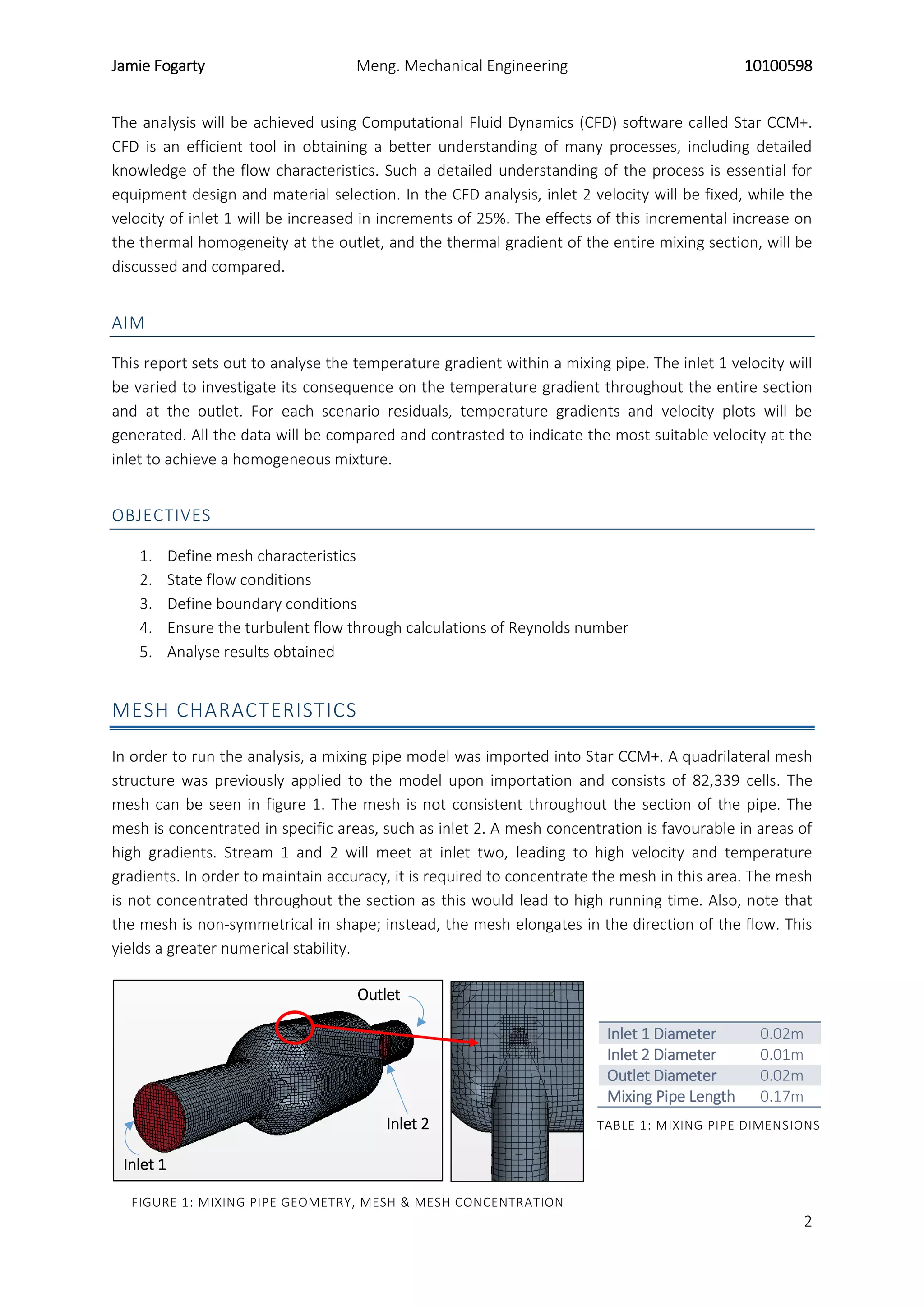
The mixing pipe under analysis in this report is a mixing pipe with no mixing elements, figure 1. Air
flows through two inlets, configured perpendicular to one another, is mixed, and exits through the
outlet. The two air streams entering have different initial conditions i.e. temperature and velocity. The
mixing of hot and cold flow streams causes high cycle temperature fluctuations, resulting in high
temperature gradients in the mixing pipe structure that induce thermal stresses. These thermal
stresses are caused as a result of the thermal expansion of a material. Thermal differentials may
produce thermal stresses significant enough to limit material life and lead to failure by fatigue failure.
Analysing both the exit temperature gradient and the entire temperature gradient will allow the
insurance of homogeneous mixing and to devise where the main thermal stresses are located. This is
turn will allow modifications to be made, if necessary.
2. Jamie Fogarty Meng. Mechanical Engineering 10100598
2
FIGURE 1: MIXING PIPE GEOMETRY, MESH & MESH CONCENTRATION
Inlet 1
Inlet 2
Outlet
The analysis will be achieved using Computational Fluid Dynamics (CFD) software called Star CCM+.
CFD is an efficient tool in obtaining a better understanding of many processes, including detailed
knowledge of the flow characteristics. Such a detailed understanding of the process is essential for
equipment design and material selection. In the CFD analysis, inlet 2 velocity will be fixed, while the
velocity of inlet 1 will be increased in increments of 25%. The effects of this incremental increase on
the thermal homogeneity at the outlet, and the thermal gradient of the entire mixing section, will be
discussed and compared.
AIM
This report sets out to analyse the temperature gradient within a mixing pipe. The inlet 1 velocity will
be varied to investigate its consequence on the temperature gradient throughout the entire section
and at the outlet. For each scenario residuals, temperature gradients and velocity plots will be
generated. All the data will be compared and contrasted to indicate the most suitable velocity at the
inlet to achieve a homogeneous mixture.
OBJECTIVES
1. Define mesh characteristics
2. State flow conditions
3. Define boundary conditions
4. Ensure the turbulent flow through calculations of Reynolds number
5. Analyse results obtained
MESH CHARACTERISTICS
In order to run the analysis, a mixing pipe model was imported into Star CCM+. A quadrilateral mesh
structure was previously applied to the model upon importation and consists of 82,339 cells. The
mesh can be seen in figure 1. The mesh is not consistent throughout the section of the pipe. The
mesh is concentrated in specific areas, such as inlet 2. A mesh concentration is favourable in areas of
high gradients. Stream 1 and 2 will meet at inlet two, leading to high velocity and temperature
gradients. In order to maintain accuracy, it is required to concentrate the mesh in this area. The mesh
is not concentrated throughout the section as this would lead to high running time. Also, note that
the mesh is non-symmetrical in shape; instead, the mesh elongates in the direction of the flow. This
yields a greater numerical stability.
Inlet 1 Diameter 0.02m
Inlet 2 Diameter 0.01m
Outlet Diameter 0.02m
Mixing Pipe Length 0.17m
TABLE 1: MIXING PIPE DIMENSIONS
3. Jamie Fogarty Meng. Mechanical Engineering 10100598
3
CFD MODELLING
FLOW CONDITIONS
The working fluid in this analysis is air, both at inlet 1 & inlet 2. The working fluid is a slightly
compressible fluid that obeys the ideal gas equation of state. The flow itself is a non-isothermal,
steady, turbulent flow whose turbulent effects are represented using the 𝑘 − 𝜀 model. K-epsilon
model is one of the most commonly used turbulent models, which is a two-equation linear eddy
viscosity model. Two transported variables in k-epsilon model are turbulent kinetic energy (k) that
determines the energy in turbulence, and turbulence dissipation (ε) which determines the scale of the
turbulence. K-epsilon has wide application and convergence for it is relatively easy for stable
solutions. Finally, the problem is solved using segregated flow solver. The Reynolds number is
calculated at both inlets for each scenario to ensure turbulent flow is present. The material properties
are displayed in table 2.
Dynamic viscosity 𝜇 = 1.86𝑥10−5
𝑃𝑎 − 𝑠
Molecular weight 𝑚 = 28.97 𝑘𝑔/𝑘𝑚𝑜𝑙
Specific heat 𝐶 = 1003.62 𝐽/𝑘𝑔𝐾
Thermal conductivity 𝑘 = 0.026 𝑊/𝑚𝐾
Turbulent Prandtl number 𝑃𝑟 = 0.9
TABLE 2: MATERIAL PROPERTIES OF THE WORKING FLUID, AIR
BOUNDARY CONDITIONS
In order for Star CMM+ to conduct the analysis, it is appropriate to define the boundary conditions for
the general flow, the wall surface and both inlets. Table 3 specifies the conditions implemented for
the velocity and direction of the flow.
Flow direction specification Boundary-Normal
Velocity specification Magnitude + direction
TABLE 3: FLOW DIRECTION AND VELOCITY SPEFICIATION
Table 4 displays that the process is adiabatic, there is no friction at the wall, no tangential velocity
(which ensures that none of the velocity vectors are lost to different directions), and no slip for the
shear stress indicating that none of the stress dissipates.
Shear stress Specification No-slip
Tangential velocity specification none
Thermal specification adiabatic
Wall surface specification smooth
TABLE 4: CONDITIONS AT THE WALL OF THE MIXING PIPE
Note that the initial conditions of pressure and static temperature are; 𝑃 = 0 𝑃𝑎, 𝑇𝑠 = 293𝐾. The
turbulence kinetic energy is 𝑘 = 0.001 𝐽/𝑘𝑔 and the turbulence dissipation is defined as 𝜖 = 𝑚2
/𝑠3
.
Table 5 defines the inlet conditions for inlet 1 and 2.
4. Jamie Fogarty Meng. Mechanical Engineering 10100598
4
Inlet 1 Inlet 2
Static Temperature 𝑇𝑠 = 298𝐾 Static Temperature 𝑇𝑠 = 373𝐾
Turbulence Intensity 0.1 Turbulence Intensity 0.1
Turbulence length scale 0.001m Turbulence length scale 0.001m
Velocity magnitude 2.5 m/s Velocity magnitude 10 m/s
Reynolds Number 3245 Reynolds number 5328
TABLE 5: INITIAL CONDITIONS AT INLET 1 & 2
Note that in this analysis, the velocity at inlet 1 is incrementally increased as per table 6.
Increase Velocity Re
25% 3.125 m/s 4056
50% 3.75 m/s 4867
75% 4.375 m/s 5678
100% 5 m/s 6489
125% 5.625 m/s 7300
TABLE 6: PERCENTAGE INCREASE IN VELOCITY MAGNITUDE AND THE CORRESPONDING VELOCITY MAGNITUDE
AT INLET 1
Finally, the outlet default boundary type was set to flow-split outlet and the maximum steps, i.e.
running criteria, was set to 500 steps.
RESULTS
The residuals are fundamentally a measure of
an iterative solutions numerical convergence,
signifying that the lower the residual the less
the results will change with further iterations.
The residual plots were generated for each
incremental increase to ensure the accuracy
of the results. Figure 2 presents the residual of
the initial analysis i.e. inlet 1 velocity = 2.5m/s.
With the velocity of inlet 2 fixed, inlet 1 was
increased in increments of 25%, as per table 6.
Two probes were implemented at the outlet of
the mixing pipe. These probes were arranged so that one ran horizontally through the centre point
and the other vertically. These probes were used to gather the temperature gradient across the
outlet. From these temperature gradients the mean deviation from the average temperature for each
inlet velocity was obtained for both the horizontal and the vertical probe. From these then, the
average of both was generated and is plotted in figure 3.
FIGURE 2: RESIDUAL PLOT. 0% INCREASED VELOCITY
5. Jamie Fogarty Meng. Mechanical Engineering 10100598
5
FIGURE 3: MEAN DEVIATION FROM AVERAGE TEMPERATURE FOR EACH INLET VELOCITY
FIGURE 4: TEMPERATURE SCALAR SCENE:
OUTLET. 0% INCREASED VELOCITY
FIGURE 5: TEMPERATURE SCALAR SCENE:
OUTLET. 50% INCREASED VELOCITY
FIGURE 2: TEMPERATURE SCALAR SCENE: ENTIRE.
0% INCREASED VELOCITY
FIGURE 6: TEMPERATURE SCALAR SCENE: ENTIRE.
50% INCREASED VELOCITY
Using Star CCM+, instantaneous scalar scenes were generated. These are a convenient method for
visually interpreting results, as a colour scale is present to signify the values of the scalars of interest.
Figures 4 & 5 display the temperature scalar scenes at the outlet for inlet 1 velocity’s 2.5 m/s and 3.75
m/s.
The same temperature scalar scenes were used to locate the maximum thermal stresses in the mixing
pipe. This can be seen figures 5 & 6.
Instantaneous velocity scalar scenes, on a plane horizontally cut through the mid-section of the
mixing pipe, were generated for each simulation. The specific one of interest are displayed in figure 7
& 8.
5
6
7
8
9
10
2.5 3.125 3.75 4.625 5 5.625
MeanTemperature
Deviation(K)
Inlet 1 velocity (m/s)
Mean deviation from
average temperature
6. Jamie Fogarty Meng. Mechanical Engineering 10100598
6
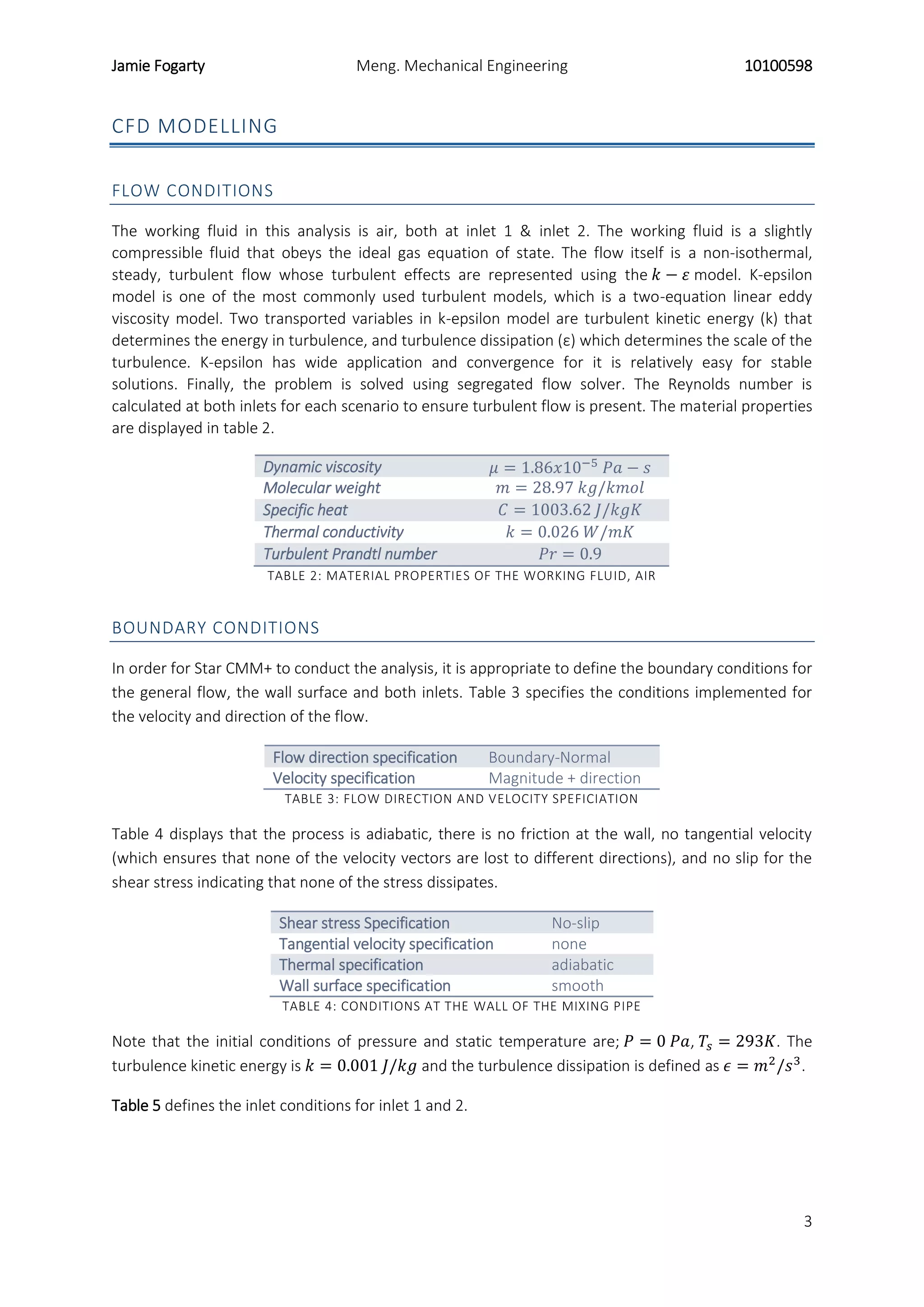
FIGURE 7: VELOCITY SCALAR SCENE. 0%
INCREASED VELOCITY
FIGURE 8: VELOCITY SCALAR SCENE. 50%
INCREASED VELOCITY
DISCUSSION
Firstly, observing figure 2, it is evident that the solution numerically converges as the residuals arrive
significantly close to zero, inclining that the results obtained reserve some accuracy.
The aim of the mixing pipe is to achieve a homogenous temperature distribution at the outlet. Figure
3 plots the mean deviation from the average temperature. This plot quantifies the deviation of the
outlet temperature from the averaged value. The plot reveals that after a 50% increase in the velocity
magnitude of inlet 1, there is a convergence. Logical and economic sense indicates that no further
increase from 50% is required, as higher percentage increases achieve a similar homogeneity and are
less cost efficient i.e. pumping power. Consequently, the discussion will focus on the comparison of
both the initial inlet 1 velocity and the 50% increased velocity.
Figure 5 presents the instantaneous temperature gradient of the entire mixing section with an inlet 1
velocity of 2.5 m/s. This figure gives insight into the mechanism behind the mixing process. In order to
produce a uniform mixture by mixing, two things need to occur. First, there must be a bulk or
convective flow so as to avoid any dead/stagnant zones i.e. turbulent inlet stream 2. Secondly, there
must be an intensive or high-shear mixing zone, in which the homogeneities are broken down i.e. the
mixing section [Zahid et al., 2013]. The cold air enters inlet one, eventually meeting a divergence
zone. As the cold air initially diverges, the velocity decreases (by continuity) and the pressure
increases (by Bernoulli). This expansion results in an energy decrease corresponding to a decrease in
temperature, represented in figure 5 as the light blue zone at the neck of the divergence zone. The
hot stream is introduced perpendicular, at a velocity magnitude 4 times greater than the cold stream,
into the mixing section. This heightened velocity gives the hot stream a higher momentum inertia,
which carries it predominantly around the perimeter of the mixing section. This is quantified as the
green zones present near the walls of the mixing section in figure 7. The turbulence of the hot stream
yields velocity fluctuations that mix transported quantities of momentum and energy resulting in
heightened heat transfer from the hot stream to the cold stream. However, due to the momentum of
the stream and the position of introduction, the hot stream follows the boundary of the mixing pipe
in the axial direction, with minimal penetration of the cold stream, which resides in the centre. This is
verified in figure 7 by the green contour (hot stream) near the mixing section boundary and the blue
contour (cold stream) in the middle. As the two streams then converge, mixing is further induced as
the cold stream penetrates the hot stream. Analysing the outlet temperature scalar scene in figure 4,
the above stated is further signified. Despite the increased mixing due to the convergence of the
mixing pipe section, the hot air accommodates the perimeter with colder air filling the centre.
7. Jamie Fogarty Meng. Mechanical Engineering 10100598
7
When the inlet velocity increases by 50% to 3.75 m/s, in the mixing section, the heightened
momentum of the cold stream allows it to better penetrate the hot stream. This can be confirmed by
the reduction in velocity characterised by the comparison of the green zones near the mixing section
boundary in the velocity scalar scenes figure 7 & 8. The velocity near the boundary of the mixing
section in figure 8 is less than that of figure 7, indicating enhanced mixing of the hot and cold stream.
Further confirming this is the outlet temperature scalar scene shown in figure 5. The temperature
gradient is reduced and the streams have more homogeneity, as the colour gradient in the scalar
scene is diminished.
Observing the thermal stresses on the mixing pipe, schematically expressed as temperature gradients
in figure 5 & 6, it is evident that adjacent from the entry of the hot stream there is a high temperature
gradient independent of the cold stream inlet velocity. Dependant on the running agenda, i.e. fixed
running, periodic running, cyclic thermal stresses may be induced in the structure of the mixing pipe,
potentially initiating a crack and leading to failure by thermal fatigue loading. This analysis pinpoints
the area where the resilience of the mixing pipe requires focus, or gives the options of selecting a
material to suit the cyclic loading. Further from this, comparing figure 4 & 5, it is clear that at an inlet
1 velocity of 3.75 m/s the thermal gradient is reduced at the outlet. This velocity proves advantageous
as it would relieve thermal stresses further from the mixing pipe, reducing the risk of thermal fatigue.
CONCLUSION
From the analysis it can be concluded that:
After an increased velocity of 50% in inlet 1 (3.75 m/s), the mean deviation from the average
temperature of the outlet converges.
In the initial simulation, due to the heightened velocity and introductory position of inlet 2,
the hot stream flows predominantly around the boundary of the mixing section with minimal
penetration from the cold stream which fills the centre. Mixing primarily occurred as the
mixing section converges. As a result, a temperature gradient reflecting this was present at
the outlet.
When the velocity of inlet 1 was increased to 3.75 m/s, improved penetration was observed
directly resulting in enhanced mixing in the mixing section and a more homogeneous outlet
mixture. Thermal stresses were relieved at the outlet as a consequence of this.
Independent of the inlet 1 conditions, a large thermal gradient was present in the mixing
section. Depending on the running agenda of the mixing pipe, material choice or design
would have to be considered to minimise the risk of thermal fatigue.
Overall, increasing the velocity of inlet 1 by 50% proves an efficient method of ensuring a more
homogeneous mixture and decreasing the thermal gradient at the outlet. Although the pumping
power required would increase, depending on the application the homogeneity of the mixture may
be of more importance. To finally conclude, at an inlet velocity of 2.5 m/s, a thermal gradient was
present at the outlet. Contingent upon the distance the required mixture has to travel after the
outlet, the initial inlet 1 velocity may be sufficient to yield the required mixture, as further from the
mixing pipe, heat transfer will continue to occur.
8. Jamie Fogarty Meng. Mechanical Engineering 10100598
8
RECCOMENDATIONS
If pressure drop was not a significant design parameter, having convergence occur over a
greater length would increase the mixing of the streams, and could potentially decrease the
thermal gradient present in the initial simulation i.e. inlet 1 velocity of 2.5 m/s. In saying this,
a balance would have to be stricken to ensure the pumping power requirement is lower than
that required for increasing the inlet 1 velocity by 50%, but still yielding the desired
homogeneity. Otherwise, this design change would not be feasible.
Changing the introduction position and/or angle of inlet 2 may influence the mixing in the
mixing section in a positive way. A computational analysis could be conducted, fixing the
initial simulation conditions, and orientating the inlet 2 differently to try minimise its
peripheral flow and increase mixing.
REFERENCES
1. Zahid HI Khokhar, MA S Al-Harthi , BF Abusharkh , HH Al-Ali , RN Sharma , HD Zughbi , AA
Shaikh , HH Redhwi , A Abdurraheem , SU Rehman , SM J Zaidi , ZU Khan , IA Hussain and BS
Yilbas, 2013, ‘Heat and Mass Transfer Mixing Enhancements in Pipe-Line; Numerical CFD and
Experimental Chores: A Review’, International Journal of Engineering Science and Innovative
Technology (IJESIT), Volume 2, Issue 1, January 2013, pg. 1-11.
2. Principles of Operation of Static Mixers - StaMixCo Static Mixer Products & Technology.
2015. Principles of Operation of Static Mixers - StaMixCo Static Mixer Products & Technology.
[ONLINE] Available at:http://www.stamixco-usa.com/principles-of-operation. [Accessed 30
September 2015].
3. Static mixing - pipe mixers. 2015. Static mixing - pipe mixers. [ONLINE] Available
at: http://www.biofuelsystems.com/pipemixers.htm. [Accessed 30 September 2015].
4. F. Hall, 1994. Building Services and Equipment: Volume 1. 3rd Edition. Routledge.