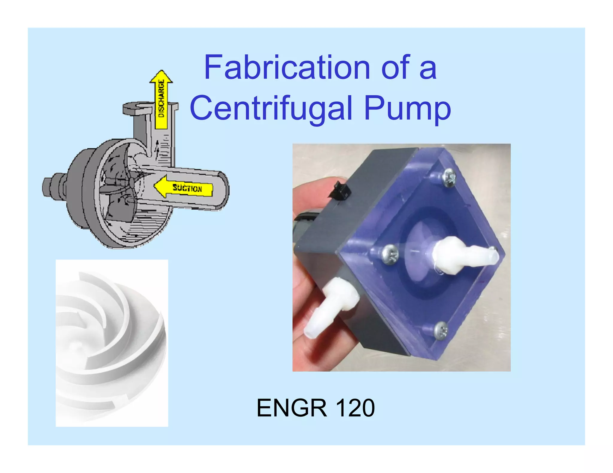
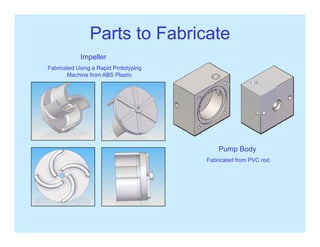
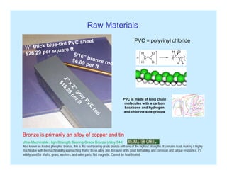
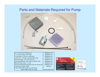
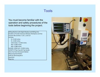
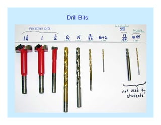
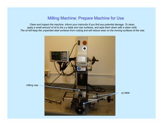
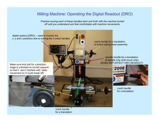
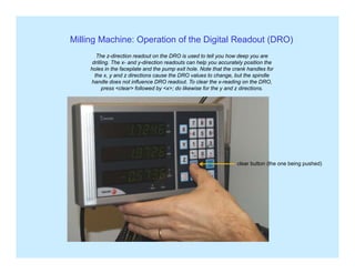
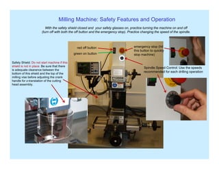
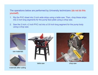
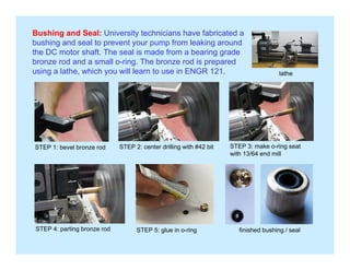
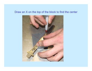
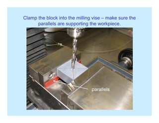
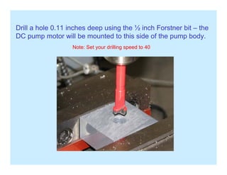
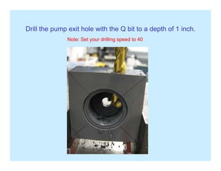
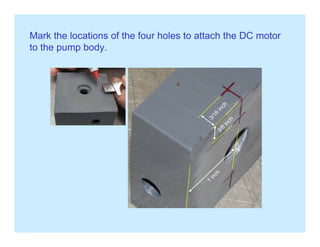
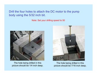
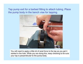
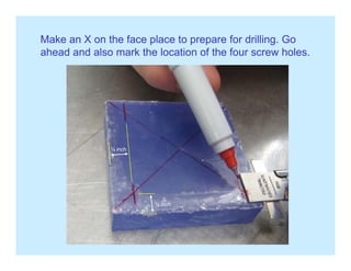
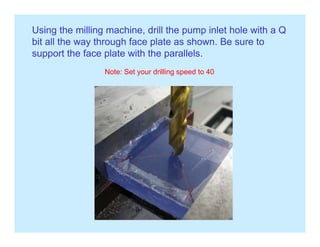
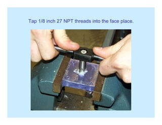
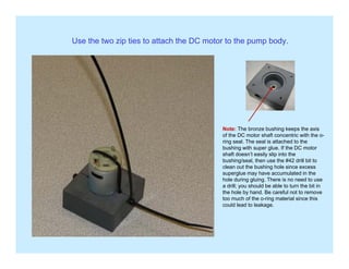
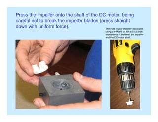
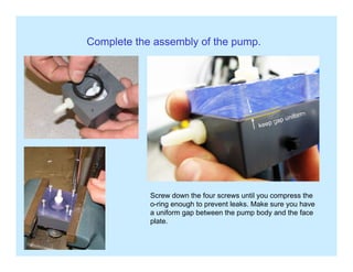
SlideShare a Scribd company logo
Fabrication of a
Centrifugal Pump
ENGR 120
Examples of Centrifugal PumpsExamples of Centrifugal Pumps
www.grpumps.com
www.oilworksinc.com
Examples of Impellers
Parts to Fabricate
Fabricated Using a Rapid Prototyping
Impeller
Machine from ABS PlasticMachine from ABS Plastic
Fabricated from PVC rod.
Pump Body
Raw Materials
PVC = polyvinyl chloride
PVC i d f l h iPVC is made of long chain
molecules with a carbon
backbone and hydrogen
and chlorine side groups
Ultra-Machinable High-Strength Bearing-Grade Bronze (Alloy 544)
Bronze is primarily an alloy of copper and tin
Ultra-Machinable High-Strength Bearing-Grade Bronze (Alloy 544)
Also known as leaded phosphor bronze, this is the best bearing-grade bronze with one of the highest strengths. It contains lead, making it highly
machinable with the machinability approaching that of brass Alloy 360. Because of its good formability, and corrosion and fatigue resistance, it's
widely used for shafts, gears, washers, and valve parts. Not magnetic. Cannot be heat treated.
Parts and Materials Required for Pump
2" x 2" x 0 9" type 1 PVC gray rod McMaster‐Carr2  x 2  x 0.9  type 1 PVC gray rod McMaster‐Carr
2" x 2" blue tint type 1 PVC sheet McMaster‐Carr
1.6 mm wide, 2.2 mm ID o‐ring (viton) McMaster‐Carr
1 1/16" ID x 1  1/4 OD o‐ring with 3/32" width McMaster‐Carr
PVC clear tubing ‐ 3/16" ID x 5/16" OD  McMaster‐Carr
nylon barbed fitting ‐ 3/16" tube ID, 1/8 NPT male McMaster‐Carr
#6 sheet metal screws 1" long McMaster Carr#6 sheet metal screws ‐ 1" long McMaster‐Carr
Ultra‐machinable bearing grade 5/16" dia. bronze rod McMaster‐Carr
8" cable ties (~0.095" wide) Walmart
9‐30V, 0.35A,4930 rpm,44.5 g‐cm DC motor 
                       (shaft: 0.090" OD & 0.45" long) Jameco Electronics
Tools
You must become familiar with the
operation and safety procedures of thep y p
tools before beginning the project.
Milling Machine with Digital Readout and Milling Vise
Parallels to Provide Clearance Between Workpiece and ViseParallels to Provide Clearance Between Workpiece and Vise
Forstner Bits (inches): 1 1/4, 1, and 1/2
Drill Bits:
        Q = 0.332 inches
        N = 0.302 inches
        5/32 inches = 0.1563 inches/
        #42 = 0.093 inches
        #44 = 0.086 inches
End Mill: 13/64 inch = 0.2031 inches
1/8 NPT 27 Pipe Tap with Tap Handle
Ultra Fine Point Permanent Marker
Measuring Scale (Ruler)
Knife for Removing Burrs
Hand Drill
Shop Vac
Drill Bits
Milling Machine: Prepare Machine for Use
Clean and inspect the machine. Inform your instructor if you find any potential damage. To clean,
apply a small amount of oil to the x-y table and vise surfaces, and wipe them down with a clean cloth.
The oil will keep the unpainted steel surfaces from rusting and will reduce wear on the moving surfaces of the vise.
milling vise
xy table
Milling Machine: Operating the Digital Readout (DRO)
Practice moving each of these handles back and forth with the machine turned
on
digital readout (DRO) – used to monitor the
d iti d t t i th 3 k h dl
g
off until you understand and feel comfortable with machine movements.
z-directi
crank handle for z-translation
of entire cutting head assembly
x, y and z positions due to turning the 3 crank handles
spindle handle for z-translation
of spindle only (drill chuck only)
(DOES NOT AFFECT DRO READOUT)
tion
Make sure lock bolt for x-direction
stage is unlocked an turned upward
z-direc
so that it won’t interfere with table
movement (or it could break off)
crank handle
for x-translation
crank handle
for y-translation
Milling Machine: Operation of the Digital Readout (DRO)
The z-direction readout on the DRO is used to tell you how deep you are
drilling. The x- and y-direction readouts can help you accurately position the
holes in the faceplate and the pump exit hole. Note that the crank handles for
the x, y and z directions cause the DRO values to change, but the spindle
handle does not influence DRO readout. To clear the x-reading on the DRO,
press <clear> followed by <x>; do likewise for the y and z directions.
clear button (the one being pushed)
Milling Machine: Safety Features and Operation
With the safety shield closed and your safety glasses on, practice turning the machine on and off
(t ff ith b th th ff b tt d th t ) P ti h i th d f th i dl
emergency stop (hit
this button to quickly
(turn off with both the off button and the emergency stop). Practice changing the speed of the spindle.
red off button
b tt
Safety Shield: Do not start machine if this
shield is not in place. Be sure that there
is adequate clearance between the
bottom of this shield and the top of the
stop machine)
Spindle Speed Control: Use the speeds
recommended for each drilling operation
green on button
bottom of this shield and the top of the
milling vise before adjusting the crank
handle for z-translation of the cutting
head assembly.
Milling Machine: Loading a Workpiece into the Vise and Tool into the Chuck
Place the parallels into the vise followed by the workpiece. Then, use
th i h dl t ti ht th lid th illi hi M k ththe vise handle to tighten the slide on the milling machine. Make sure the
workpiece is securely clamped in the vise before beginning work.
load drill bit or other
tool into chuck and
tighten with key
nut for locking down
x stage of x-y table (be
careful not to move the
y-stage if this nut is
downward (make sure(
it’s pointing upward), or
you could break off the
nut.
Don’t forget to
Remove key
vise handle
y
from chuck!
vise handle
Safety RulesSafety Rules
1. Do not operate any machine unless authorized to do so by the instructor.
2 D t tt t t il l dj t i hi hil it i i ti2. Do not attempt to oil, clean, adjust or repair any machine while it is in operation.
3. Wear appropriate clothing for the work to be done – loose clothing can be caught
up in rotating equipment, pulling you into the equipment.
4. No “horse play” is allowed in the lab.
5. To prevent tripping or cutting a foot, keep floor clear of scraps, chips and supplies.
6 Turn off the equipment you are using before leaving it6. Turn off the equipment you are using before leaving it.
7. Safety glasses or a face shield must be worn when using tools or equipment.
8. Put tools away when not in use.
9. Do not use rags on rotating work.
10. Do not attempt to hold work with rags while using any rotating equipment.
11. Long hair must be tucked under a cap when you are operating rotating equipment.
12. Report any unsafe working conditions and/or practices to the instructor.
13. Take all common sense precautions. If you have an accident, report it immediately
to the instructor.
Do not begin to fabricate your pump until you have
carefully read the operating and safety instructions
above and agree to operate the equipment in a
responsible manner. You must sign the safety
contract before beginning fabrication.
The operations below are performed by University technicians (do not do this
yourself).yourself).
1. Rip the PVC sheet into 2 inch wide strips using a table saw. Then, chop these strips
into 2 inch long segments for the pump face plate using a chop saw.
2. Saw the 2 inch x 2 inch PVC rod into a 0.9 inch long segment for the pump body
using a chop saw.
raw materialsraw materials
table saw chop saw
materials after cutting
Bushing and Seal: University technicians have fabricated a
bushing and seal to prevent your pump from leaking around
th DC t h ft Th l i d f b i dthe DC motor shaft. The seal is made from a bearing grade
bronze rod and a small o-ring. The bronze rod is prepared
using a lathe, which you will learn to use in ENGR 121. lathe
STEP 1: bevel bronze rod STEP 2: center drilling with #42 bit STEP 3: make o-ring seat
ith 13/64 d illwith 13/64 end mill
STEP 4: parting bronze rod STEP 5: glue in o-ring finished bushing / seal
Draw an X on the top of the block to find the centerp
Clamp the block into the milling vise – make sure the
ll l ti th k iparallels are supporting the workpiece.
parallels
Put the N bit into the chuck. Turn the crank handles to move the x-y table until the bit
is directly over the “x.” Then tighten down the x- and y-table lock bolts so the table
won’t move in the subsequent steps The lock bolts can get hung up on the x-y tablewon t move in the subsequent steps. The lock bolts can get hung up on the x y table
when you are moving it, so check to make sure there isn’t any interference.
lock bolt for x-directionoc bo t o d ect o
Drill N bit hole all the way through block (but not into the vise!!!).
You can use either the crank handle or the spindle handle.p
crank handle for z translationcrank handle for z-translation
of entire cutting head assembly
spindle handle for z translationspindle handle for z-translation
of spindle only (drill chuck only)
(DOES NOT AFFECT DRO READOUT)
Note: Set the drilling speed to 40.
Install the 1 ¼ inch Forstner bit into the chuck. You may need to raise
the cutting head to provide room to get the bit into the chuck. After the
bit is in and the safety shield is in place, turn the spindle on. Then,
lower the cutting head with the z-crank handle until the bit begins to cut
h 1 ¼ i h h l Z h di i h DRO d d ill d ilthe 1 ¼ inch hole. Zero the z-direction on the DRO, and drill down until
the depth is about 0.080 inches.
Note: Set your drilling speed to 30
Install the 1 inch Forstner bit, bring the cutting head down until the bit
begins to cut into the block at the bottom of the previous hole. Drill anbegins to cut into the block at the bottom of the previous hole. Drill an
additional 0.42 inches deeper (for a total depth of ½ inch from the top
surface of the block).
Note: Set your drilling speed to 30y g p
Expect chips to wrap
Warning The drill bit may be very hot
Expect chips to wrap
around the bit during
drilling
Warning – The drill bit may be very hot.
Use a rag or cloth to remove.
Unlock the x- and y-stage lock bolts and remove the block
from the vise. Flip the pump body over, doing your best to
b h i f h h l d ill d li i id i h hbe sure the axis of the hole drilled earlier coincides with the
axis of the spindle. To check this, place the N bit back into
the chuck, and move the x- and y-stages until the bit is, y g
aligned with the hole. Now, remove the N bit and replace it
with the ½ inch Forstner bit.
Drill a hole 0.11 inches deep using the ½ inch Forstner bit – the
DC pump motor will be mounted to this side of the pump body.
Note: Set your drilling speed to 40
Mark hole for pump outlet as shown below. The exit shouldMark hole for pump outlet as shown below. The exit should
roughly be tangent to the 1 inch Forstner hole.
drill hole here
bit is tangent to 1 inch hole
Drill the pump exit hole with the Q bit to a depth of 1 inch.p p p
Note: Set your drilling speed to 40
Mark the locations of the four holes to attach the DC motor
to the pump bodyto the pump body.
Drill the four holes to attach the DC motor to the pump
body using the 5/32 inch bit.
Note: Set your drilling speed to 50
The hole being drilled in this
picture should be 7/16 inch deep.
The hole being drilled in this
picture should be 1/4 inch deep.
Tap pump exit for a barbed fitting to attach tubing. Place
th b d i th b h i f t ithe pump body in the bench vise for tapping.
You will need to apply a little bit of axial force to the tap as you get itpp y p y g
started in the hole. While you are doing this, keep checking to be sure
your tap is perpendicular to the pump body.
Press the bronze bushing with the o-ring seal into the pump
body until the bushing is flush with the bottom of the 0.11body until the bushing is flush with the bottom of the 0.11
inch diameter hole. Completely close the jaws of the chuck,
and use the z-crank handle to apply the pressing force.
We normally don’t use the milling machine as a press, but it’s OK here since pressing forces are small.y g p , p g
Make an X on the face place to prepare for drilling. Go
h d d l k th l ti f th f h lahead and also mark the location of the four screw holes.
¼ inch
¼ inch
Using the milling machine, drill the pump inlet hole with a Q
bit all the way through face plate as shown. Be sure toy g p
support the face plate with the parallels.
Note: Set your drilling speed to 40
Using the milling machine, drill the four screw holes into the
face plate using a #42 drill bit.face plate using a #42 drill bit.
Note: Set your drilling speed to 50
Tap 1/8 inch 27 NPT threads into the face place.p p
Make alignment marks on the pump body and face plate.g p p y p
Clamp the pump body to the
f l t h
Cutting marks into work
pieces keeps them from
pump face plate as shown.
Place the clamped parts in the bench vise as shown, and
k li t k l li th f
rubbing off.
make alignment marks so you can properly align the face
plate to the pump body during later assembly steps.
alignment marks
Leave the clamped parts in the bench vise. Using the four holes in the face
plate as a guide, drill #42 holes deep into pump body (don’t go quite all the way
through) using a hand drill (this is not done in the milling machine).
Be sure to keep the drill perpendicular
to the workpiece to avoid breaking the
drill bit.
NOTE: The drill is variable speed; practice using the drill without a bit first trying to keep the
rotational speed of the drill low for safety. Work toward slow and controlled motion (don’t put
your body weight into the drill since suddenly breaking through the workpiece is dangerous).
Never use the hand drill unless the workpiece is clamped in the vise.
Mount the face plate in the vise. Chase the #42 holes in the face plate with a 5/32
inch bit using a hand drill to provide clearance between the screw and the face
plateplate.
dhole > dscrew
d
dscrew
dhole
Important: Oversizing these holes allows the screws to easily slide through. The o-ring
between the faceplate and body can’t be properly compressed unless these holes have a
diameter larger than the screws.
Apply Teflon tape to the two barbed fittings and then screw them into the pumpApply Teflon tape to the two barbed fittings, and then screw them into the pump
body and into the face plate. Teflon tape helps prevent leaking.
Use the two zip ties to attach the DC motor to the pump body.
Note: The bronze bushing keeps the axis
of the DC motor shaft concentric with the o-
ring seal. The seal is attached to the
bushing with super glue. If the DC motor
shaft doesn’t easily slip into the
bushing/seal, then use the #42 drill bit to
clean out the bushing hole since excess
superglue may have accumulated in the
hole during gluing. There is no need to use
a drill; you should be able to turn the bit ina drill; you should be able to turn the bit in
the hole by hand. Be careful not to remove
too much of the o-ring material since this
could lead to leakage.
Lubricate around the o-ring, being careful not to get lubricant on the
motor shaft (since the impeller might slip relative to the pump shaft if( p g p p p
the contact interface is lubricated).
When using the pump later, be careful not to run the pump dry, since the o-ring
seal could get too hot and be damaged, resulting in a leaky pump.
Press the impeller onto the shaft of the DC motor, being
careful not to break the impeller blades (press straightp (p g
down with uniform force). The hole in your impeller was sized
using a #44 drill bit for a 0.005 inch
interference fit between the impeller
and the DC motor shaft.and the DC motor shaft.
Complete the assembly of the pump.
Screw down the four screws until you compress the
o-ring enough to prevent leaks. Make sure you have
a uniform gap between the pump body and the face
plateplate.
Clean up your mess. Make it look better when you leave
than it looked when you arrived. Take pride in your lab!!!
Step 1: Brush the larger chips Step 2: Vacuum up any remaining Step 3: Wipe the machinep g p
off the machine and vises,
collecting them in the dustpan.
Dispose of them in the
trashcan.
p p y g
small chips (do not vacuum large
chips since it will plug up the
vacuum cleaner.
p p
and the countertop in your
area with a rag (an oily rag
will keep the milling machine
from rusting).
Step 4: Put all drill bits and the chuck key back into their holder and organize your work area. Inform
your instructor is anything is broken, damaged or lost before leaving the classroom.
Show the instructor your pump and that your workstation is put back in order.y p p y p

More Related Content

What's hot

Understanding Rotary Toolholders
Understanding Rotary ToolholdersUnderstanding Rotary Toolholders
Understanding Rotary Toolholders
Rapid Production Marketing
 
2009-Tooling-Manual
2009-Tooling-Manual2009-Tooling-Manual
2009-Tooling-Manual
Sandeep Aulakh
 
Toyota 02 5fg23 forklift service repair manual
Toyota 02 5fg23 forklift service repair manualToyota 02 5fg23 forklift service repair manual
Toyota 02 5fg23 forklift service repair manual
fjsjekkdmnem
 
Toyota 02 5fd23 forklift service repair manual
Toyota 02 5fd23 forklift service repair manualToyota 02 5fd23 forklift service repair manual
Toyota 02 5fd23 forklift service repair manual
fjkskedmme
 
Toyota 02 5fg15 forklift service repair manual
Toyota 02 5fg15 forklift service repair manualToyota 02 5fg15 forklift service repair manual
Toyota 02 5fg15 forklift service repair manual
fjjskekdm
 
Drill press cutting tool operating instructions
Drill press cutting tool operating instructionsDrill press cutting tool operating instructions
Drill press cutting tool operating instructions
Carter Manufacturing Limited
 
Tool box talk power point 3
Tool box talk power point 3Tool box talk power point 3
Tool box talk power point 3
Larry Wleczyk
 
Cabina arenadora vertical Granalladora Equus
Cabina arenadora vertical Granalladora EquusCabina arenadora vertical Granalladora Equus
Cabina arenadora vertical Granalladora Equus
KarlianaStanziolaDav
 
HITACHI 4HK1 ENGINE Service Repair Manual
HITACHI 4HK1 ENGINE Service Repair ManualHITACHI 4HK1 ENGINE Service Repair Manual
HITACHI 4HK1 ENGINE Service Repair Manual
jnfmmsd ejdkmsm
 
Raccordi per alte pressioni - Fitok serie 15
Raccordi per alte pressioni - Fitok serie 15Raccordi per alte pressioni - Fitok serie 15
Raccordi per alte pressioni - Fitok serie 15
GIGA TECH SRL - Distribuzione componenti per impianti di processo
 
Toyota 52 6 fgcu20 forklift service repair manual
Toyota 52 6 fgcu20 forklift service repair manualToyota 52 6 fgcu20 forklift service repair manual
Toyota 52 6 fgcu20 forklift service repair manual
jfskemsemm
 
Example_Prorack HD iLoad Track Kit Instructions
Example_Prorack HD iLoad Track Kit InstructionsExample_Prorack HD iLoad Track Kit Instructions
Example_Prorack HD iLoad Track Kit Instructions
Jessica Smith
 
YDM Laboratory Technique Catalogue
YDM Laboratory Technique CatalogueYDM Laboratory Technique Catalogue
YDM Laboratory Technique Catalogue
vlnkhn
 
Hitachi 4 hk1 engine service repair manual
Hitachi 4 hk1 engine service repair manualHitachi 4 hk1 engine service repair manual
Hitachi 4 hk1 engine service repair manual
jkmsedopl
 
Hitachi 6 hk1 engine service repair manual
Hitachi 6 hk1 engine service repair manualHitachi 6 hk1 engine service repair manual
Hitachi 6 hk1 engine service repair manual
fjjsjekksemm
 
Hitachi 6 hk1 engine service repair manual
Hitachi 6 hk1 engine service repair manualHitachi 6 hk1 engine service repair manual
Hitachi 6 hk1 engine service repair manual
hjsnmdmme
 
Toyota 5FD60 Forklift Service Repair Manual
Toyota 5FD60 Forklift Service Repair ManualToyota 5FD60 Forklift Service Repair Manual
Toyota 5FD60 Forklift Service Repair Manual
ukjkme kjdmfkm
 

What's hot (17)

Understanding Rotary Toolholders
Understanding Rotary ToolholdersUnderstanding Rotary Toolholders
Understanding Rotary Toolholders
 
2009-Tooling-Manual
2009-Tooling-Manual2009-Tooling-Manual
2009-Tooling-Manual
 
Toyota 02 5fg23 forklift service repair manual
Toyota 02 5fg23 forklift service repair manualToyota 02 5fg23 forklift service repair manual
Toyota 02 5fg23 forklift service repair manual
 
Toyota 02 5fd23 forklift service repair manual
Toyota 02 5fd23 forklift service repair manualToyota 02 5fd23 forklift service repair manual
Toyota 02 5fd23 forklift service repair manual
 
Toyota 02 5fg15 forklift service repair manual
Toyota 02 5fg15 forklift service repair manualToyota 02 5fg15 forklift service repair manual
Toyota 02 5fg15 forklift service repair manual
 
Drill press cutting tool operating instructions
Drill press cutting tool operating instructionsDrill press cutting tool operating instructions
Drill press cutting tool operating instructions
 
Tool box talk power point 3
Tool box talk power point 3Tool box talk power point 3
Tool box talk power point 3
 
Cabina arenadora vertical Granalladora Equus
Cabina arenadora vertical Granalladora EquusCabina arenadora vertical Granalladora Equus
Cabina arenadora vertical Granalladora Equus
 
HITACHI 4HK1 ENGINE Service Repair Manual
HITACHI 4HK1 ENGINE Service Repair ManualHITACHI 4HK1 ENGINE Service Repair Manual
HITACHI 4HK1 ENGINE Service Repair Manual
 
Raccordi per alte pressioni - Fitok serie 15
Raccordi per alte pressioni - Fitok serie 15Raccordi per alte pressioni - Fitok serie 15
Raccordi per alte pressioni - Fitok serie 15
 
Toyota 52 6 fgcu20 forklift service repair manual
Toyota 52 6 fgcu20 forklift service repair manualToyota 52 6 fgcu20 forklift service repair manual
Toyota 52 6 fgcu20 forklift service repair manual
 
Example_Prorack HD iLoad Track Kit Instructions
Example_Prorack HD iLoad Track Kit InstructionsExample_Prorack HD iLoad Track Kit Instructions
Example_Prorack HD iLoad Track Kit Instructions
 
YDM Laboratory Technique Catalogue
YDM Laboratory Technique CatalogueYDM Laboratory Technique Catalogue
YDM Laboratory Technique Catalogue
 
Hitachi 4 hk1 engine service repair manual
Hitachi 4 hk1 engine service repair manualHitachi 4 hk1 engine service repair manual
Hitachi 4 hk1 engine service repair manual
 
Hitachi 6 hk1 engine service repair manual
Hitachi 6 hk1 engine service repair manualHitachi 6 hk1 engine service repair manual
Hitachi 6 hk1 engine service repair manual
 
Hitachi 6 hk1 engine service repair manual
Hitachi 6 hk1 engine service repair manualHitachi 6 hk1 engine service repair manual
Hitachi 6 hk1 engine service repair manual
 
Toyota 5FD60 Forklift Service Repair Manual
Toyota 5FD60 Forklift Service Repair ManualToyota 5FD60 Forklift Service Repair Manual
Toyota 5FD60 Forklift Service Repair Manual
 

Similar to Centrifugal pump fabrication

Thread cutting presentation
Thread cutting presentationThread cutting presentation
Thread cutting presentation
Rayon Johnson
 
MANUFACTURING PROJECT TECHNICAL REPORT
MANUFACTURING PROJECT TECHNICAL REPORTMANUFACTURING PROJECT TECHNICAL REPORT
MANUFACTURING PROJECT TECHNICAL REPORT
Kendrick Thomas
 
Jointer
JointerJointer
Jointer
dmducan
 
Work Precedure Side Standard
Work Precedure Side StandardWork Precedure Side Standard
Work Precedure Side Standard
Christopher (C.G.) Cruz
 
Work Precedure for Front standard
Work Precedure for Front standardWork Precedure for Front standard
Work Precedure for Front standard
Christopher (C.G.) Cruz
 
F-F-Fiddle Assembly Instructions
F-F-Fiddle Assembly InstructionsF-F-Fiddle Assembly Instructions
F-F-Fiddle Assembly Instructions
dsp39
 
007 drilling
007 drilling007 drilling
007 drilling
physics101
 
Lab manual workshop
Lab manual workshopLab manual workshop
Lab manual workshop
Tanveer Hussain
 
Mounting Instructions | C-More Serendipity Red Dot Sights | Optics Trade
Mounting Instructions | C-More Serendipity Red Dot Sights | Optics TradeMounting Instructions | C-More Serendipity Red Dot Sights | Optics Trade
Mounting Instructions | C-More Serendipity Red Dot Sights | Optics Trade
Optics-Trade
 
Instruction Manual C-MORE Serendipity Mounting | Optics Trade
Instruction Manual C-MORE Serendipity Mounting | Optics TradeInstruction Manual C-MORE Serendipity Mounting | Optics Trade
Instruction Manual C-MORE Serendipity Mounting | Optics Trade
Optics-Trade
 
RhinoCAM_RotaryPrimer_MachineSetup
RhinoCAM_RotaryPrimer_MachineSetupRhinoCAM_RotaryPrimer_MachineSetup
RhinoCAM_RotaryPrimer_MachineSetup
NYCCTfab
 
Drilling machine metal woprk
Drilling machine  metal woprkDrilling machine  metal woprk
Drilling machine metal woprk
garfield Tulloch
 
2004 0520 Tx
2004 0520 Tx2004 0520 Tx
2004 0520 Tx
TRIC Tools
 
Rt 40-rev-2
Rt 40-rev-2Rt 40-rev-2
Rt 40-rev-2
Gustavo Cardozo
 
Caterpillar cat 951 b track loader (prefix 69h) service repair manual (69h036...
Caterpillar cat 951 b track loader (prefix 69h) service repair manual (69h036...Caterpillar cat 951 b track loader (prefix 69h) service repair manual (69h036...
Caterpillar cat 951 b track loader (prefix 69h) service repair manual (69h036...
fjskefksemer
 
Caterpillar cat 951 c track loader (prefix 69h) service repair manual (69h036...
Caterpillar cat 951 c track loader (prefix 69h) service repair manual (69h036...Caterpillar cat 951 c track loader (prefix 69h) service repair manual (69h036...
Caterpillar cat 951 c track loader (prefix 69h) service repair manual (69h036...
fujsekfkksemm
 
Caterpillar cat 951 b track loader (prefix 69h) service repair manual (69h036...
Caterpillar cat 951 b track loader (prefix 69h) service repair manual (69h036...Caterpillar cat 951 b track loader (prefix 69h) service repair manual (69h036...
Caterpillar cat 951 b track loader (prefix 69h) service repair manual (69h036...
fjjskkdmnsme
 
Caterpillar cat 951 b track loader (prefix 69h) service repair manual (69h036...
Caterpillar cat 951 b track loader (prefix 69h) service repair manual (69h036...Caterpillar cat 951 b track loader (prefix 69h) service repair manual (69h036...
Caterpillar cat 951 b track loader (prefix 69h) service repair manual (69h036...
udfjsjkkksme
 
Caterpillar cat 951 c track loader (prefix 69h) service repair manual (69h036...
Caterpillar cat 951 c track loader (prefix 69h) service repair manual (69h036...Caterpillar cat 951 c track loader (prefix 69h) service repair manual (69h036...
Caterpillar cat 951 c track loader (prefix 69h) service repair manual (69h036...
fujsjefskekm
 
Caterpillar cat 951 c track loader (prefix 69h) service repair manual (69h036...
Caterpillar cat 951 c track loader (prefix 69h) service repair manual (69h036...Caterpillar cat 951 c track loader (prefix 69h) service repair manual (69h036...
Caterpillar cat 951 c track loader (prefix 69h) service repair manual (69h036...
uufjjdjkfkkskem
 

Similar to Centrifugal pump fabrication (20)

Thread cutting presentation
Thread cutting presentationThread cutting presentation
Thread cutting presentation
 
MANUFACTURING PROJECT TECHNICAL REPORT
MANUFACTURING PROJECT TECHNICAL REPORTMANUFACTURING PROJECT TECHNICAL REPORT
MANUFACTURING PROJECT TECHNICAL REPORT
 
Jointer
JointerJointer
Jointer
 
Work Precedure Side Standard
Work Precedure Side StandardWork Precedure Side Standard
Work Precedure Side Standard
 
Work Precedure for Front standard
Work Precedure for Front standardWork Precedure for Front standard
Work Precedure for Front standard
 
F-F-Fiddle Assembly Instructions
F-F-Fiddle Assembly InstructionsF-F-Fiddle Assembly Instructions
F-F-Fiddle Assembly Instructions
 
007 drilling
007 drilling007 drilling
007 drilling
 
Lab manual workshop
Lab manual workshopLab manual workshop
Lab manual workshop
 
Mounting Instructions | C-More Serendipity Red Dot Sights | Optics Trade
Mounting Instructions | C-More Serendipity Red Dot Sights | Optics TradeMounting Instructions | C-More Serendipity Red Dot Sights | Optics Trade
Mounting Instructions | C-More Serendipity Red Dot Sights | Optics Trade
 
Instruction Manual C-MORE Serendipity Mounting | Optics Trade
Instruction Manual C-MORE Serendipity Mounting | Optics TradeInstruction Manual C-MORE Serendipity Mounting | Optics Trade
Instruction Manual C-MORE Serendipity Mounting | Optics Trade
 
RhinoCAM_RotaryPrimer_MachineSetup
RhinoCAM_RotaryPrimer_MachineSetupRhinoCAM_RotaryPrimer_MachineSetup
RhinoCAM_RotaryPrimer_MachineSetup
 
Drilling machine metal woprk
Drilling machine  metal woprkDrilling machine  metal woprk
Drilling machine metal woprk
 
2004 0520 Tx
2004 0520 Tx2004 0520 Tx
2004 0520 Tx
 
Rt 40-rev-2
Rt 40-rev-2Rt 40-rev-2
Rt 40-rev-2
 
Caterpillar cat 951 b track loader (prefix 69h) service repair manual (69h036...
Caterpillar cat 951 b track loader (prefix 69h) service repair manual (69h036...Caterpillar cat 951 b track loader (prefix 69h) service repair manual (69h036...
Caterpillar cat 951 b track loader (prefix 69h) service repair manual (69h036...
 
Caterpillar cat 951 c track loader (prefix 69h) service repair manual (69h036...
Caterpillar cat 951 c track loader (prefix 69h) service repair manual (69h036...Caterpillar cat 951 c track loader (prefix 69h) service repair manual (69h036...
Caterpillar cat 951 c track loader (prefix 69h) service repair manual (69h036...
 
Caterpillar cat 951 b track loader (prefix 69h) service repair manual (69h036...
Caterpillar cat 951 b track loader (prefix 69h) service repair manual (69h036...Caterpillar cat 951 b track loader (prefix 69h) service repair manual (69h036...
Caterpillar cat 951 b track loader (prefix 69h) service repair manual (69h036...
 
Caterpillar cat 951 b track loader (prefix 69h) service repair manual (69h036...
Caterpillar cat 951 b track loader (prefix 69h) service repair manual (69h036...Caterpillar cat 951 b track loader (prefix 69h) service repair manual (69h036...
Caterpillar cat 951 b track loader (prefix 69h) service repair manual (69h036...
 
Caterpillar cat 951 c track loader (prefix 69h) service repair manual (69h036...
Caterpillar cat 951 c track loader (prefix 69h) service repair manual (69h036...Caterpillar cat 951 c track loader (prefix 69h) service repair manual (69h036...
Caterpillar cat 951 c track loader (prefix 69h) service repair manual (69h036...
 
Caterpillar cat 951 c track loader (prefix 69h) service repair manual (69h036...
Caterpillar cat 951 c track loader (prefix 69h) service repair manual (69h036...Caterpillar cat 951 c track loader (prefix 69h) service repair manual (69h036...
Caterpillar cat 951 c track loader (prefix 69h) service repair manual (69h036...
 

More from Khiem Vo Duy

Inspection manual for piping
Inspection manual for pipingInspection manual for piping
Inspection manual for piping
Khiem Vo Duy
 
Copper tube handbook
Copper tube handbookCopper tube handbook
Copper tube handbook
Khiem Vo Duy
 
Corrosion in-centrifugal-pumps
Corrosion in-centrifugal-pumpsCorrosion in-centrifugal-pumps
Corrosion in-centrifugal-pumps
Khiem Vo Duy
 
Centrifugal pump
Centrifugal pumpCentrifugal pump
Centrifugal pump
Khiem Vo Duy
 
20 pump manual desmi
20 pump manual desmi20 pump manual desmi
20 pump manual desmi
Khiem Vo Duy
 
So tay chang buoc hang hoa
So tay chang buoc hang hoaSo tay chang buoc hang hoa
So tay chang buoc hang hoa
Khiem Vo Duy
 
6f terminals container cranes
6f terminals container cranes6f terminals container cranes
6f terminals container cranes
Khiem Vo Duy
 
01 pressure basic1
01 pressure basic101 pressure basic1
01 pressure basic1
Khiem Vo Duy
 
Giao trinh van cong nghiep
Giao trinh van cong nghiepGiao trinh van cong nghiep
Giao trinh van cong nghiep
Khiem Vo Duy
 
Tai lieu huong dan nhiem vu e&amp;i inspector
Tai lieu huong dan nhiem vu e&amp;i inspectorTai lieu huong dan nhiem vu e&amp;i inspector
Tai lieu huong dan nhiem vu e&amp;i inspector
Khiem Vo Duy
 
Quy trình lắp đặt e&amp;i 2012
Quy trình lắp đặt e&amp;i 2012Quy trình lắp đặt e&amp;i 2012
Quy trình lắp đặt e&amp;i 2012
Khiem Vo Duy
 

More from Khiem Vo Duy (11)

Inspection manual for piping
Inspection manual for pipingInspection manual for piping
Inspection manual for piping
 
Copper tube handbook
Copper tube handbookCopper tube handbook
Copper tube handbook
 
Corrosion in-centrifugal-pumps
Corrosion in-centrifugal-pumpsCorrosion in-centrifugal-pumps
Corrosion in-centrifugal-pumps
 
Centrifugal pump
Centrifugal pumpCentrifugal pump
Centrifugal pump
 
20 pump manual desmi
20 pump manual desmi20 pump manual desmi
20 pump manual desmi
 
So tay chang buoc hang hoa
So tay chang buoc hang hoaSo tay chang buoc hang hoa
So tay chang buoc hang hoa
 
6f terminals container cranes
6f terminals container cranes6f terminals container cranes
6f terminals container cranes
 
01 pressure basic1
01 pressure basic101 pressure basic1
01 pressure basic1
 
Giao trinh van cong nghiep
Giao trinh van cong nghiepGiao trinh van cong nghiep
Giao trinh van cong nghiep
 
Tai lieu huong dan nhiem vu e&amp;i inspector
Tai lieu huong dan nhiem vu e&amp;i inspectorTai lieu huong dan nhiem vu e&amp;i inspector
Tai lieu huong dan nhiem vu e&amp;i inspector
 
Quy trình lắp đặt e&amp;i 2012
Quy trình lắp đặt e&amp;i 2012Quy trình lắp đặt e&amp;i 2012
Quy trình lắp đặt e&amp;i 2012
 

Recently uploaded

Engineering Drawings Lecture Detail Drawings 2014.pdf
Engineering Drawings Lecture Detail Drawings 2014.pdfEngineering Drawings Lecture Detail Drawings 2014.pdf
Engineering Drawings Lecture Detail Drawings 2014.pdf
abbyasa1014
 
Textile Chemical Processing and Dyeing.pdf
Textile Chemical Processing and Dyeing.pdfTextile Chemical Processing and Dyeing.pdf
Textile Chemical Processing and Dyeing.pdf
NazakatAliKhoso2
 
Heat Resistant Concrete Presentation ppt
Heat Resistant Concrete Presentation pptHeat Resistant Concrete Presentation ppt
Heat Resistant Concrete Presentation ppt
mamunhossenbd75
 
Redefining brain tumor segmentation: a cutting-edge convolutional neural netw...
Redefining brain tumor segmentation: a cutting-edge convolutional neural netw...Redefining brain tumor segmentation: a cutting-edge convolutional neural netw...
Redefining brain tumor segmentation: a cutting-edge convolutional neural netw...
IJECEIAES
 
Harnessing WebAssembly for Real-time Stateless Streaming Pipelines
Harnessing WebAssembly for Real-time Stateless Streaming PipelinesHarnessing WebAssembly for Real-time Stateless Streaming Pipelines
Harnessing WebAssembly for Real-time Stateless Streaming Pipelines
Christina Lin
 
Presentation of IEEE Slovenia CIS (Computational Intelligence Society) Chapte...
Presentation of IEEE Slovenia CIS (Computational Intelligence Society) Chapte...Presentation of IEEE Slovenia CIS (Computational Intelligence Society) Chapte...
Presentation of IEEE Slovenia CIS (Computational Intelligence Society) Chapte...
University of Maribor
 
22CYT12-Unit-V-E Waste and its Management.ppt
22CYT12-Unit-V-E Waste and its Management.ppt22CYT12-Unit-V-E Waste and its Management.ppt
22CYT12-Unit-V-E Waste and its Management.ppt
KrishnaveniKrishnara1
 
DEEP LEARNING FOR SMART GRID INTRUSION DETECTION: A HYBRID CNN-LSTM-BASED MODEL
DEEP LEARNING FOR SMART GRID INTRUSION DETECTION: A HYBRID CNN-LSTM-BASED MODELDEEP LEARNING FOR SMART GRID INTRUSION DETECTION: A HYBRID CNN-LSTM-BASED MODEL
DEEP LEARNING FOR SMART GRID INTRUSION DETECTION: A HYBRID CNN-LSTM-BASED MODEL
gerogepatton
 
学校原版美国波士顿大学毕业证学历学位证书原版一模一样
学校原版美国波士顿大学毕业证学历学位证书原版一模一样学校原版美国波士顿大学毕业证学历学位证书原版一模一样
学校原版美国波士顿大学毕业证学历学位证书原版一模一样
171ticu
 
Understanding Inductive Bias in Machine Learning
Understanding Inductive Bias in Machine LearningUnderstanding Inductive Bias in Machine Learning
Understanding Inductive Bias in Machine Learning
SUTEJAS
 
ACEP Magazine edition 4th launched on 05.06.2024
ACEP Magazine edition 4th launched on 05.06.2024ACEP Magazine edition 4th launched on 05.06.2024
ACEP Magazine edition 4th launched on 05.06.2024
Rahul
 
132/33KV substation case study Presentation
132/33KV substation case study Presentation132/33KV substation case study Presentation
132/33KV substation case study Presentation
kandramariana6
 
Embedded machine learning-based road conditions and driving behavior monitoring
Embedded machine learning-based road conditions and driving behavior monitoringEmbedded machine learning-based road conditions and driving behavior monitoring
Embedded machine learning-based road conditions and driving behavior monitoring
IJECEIAES
 
Computational Engineering IITH Presentation
Computational Engineering IITH PresentationComputational Engineering IITH Presentation
Computational Engineering IITH Presentation
co23btech11018
 
BPV-GUI-01-Guide-for-ASME-Review-Teams-(General)-10-10-2023.pdf
BPV-GUI-01-Guide-for-ASME-Review-Teams-(General)-10-10-2023.pdfBPV-GUI-01-Guide-for-ASME-Review-Teams-(General)-10-10-2023.pdf
BPV-GUI-01-Guide-for-ASME-Review-Teams-(General)-10-10-2023.pdf
MIGUELANGEL966976
 
New techniques for characterising damage in rock slopes.pdf
New techniques for characterising damage in rock slopes.pdfNew techniques for characterising damage in rock slopes.pdf
New techniques for characterising damage in rock slopes.pdf
wisnuprabawa3
 
Engine Lubrication performance System.pdf
Engine Lubrication performance System.pdfEngine Lubrication performance System.pdf
Engine Lubrication performance System.pdf
mamamaam477
 
Manufacturing Process of molasses based distillery ppt.pptx
Manufacturing Process of molasses based distillery ppt.pptxManufacturing Process of molasses based distillery ppt.pptx
Manufacturing Process of molasses based distillery ppt.pptx
Madan Karki
 
Optimizing Gradle Builds - Gradle DPE Tour Berlin 2024
Optimizing Gradle Builds - Gradle DPE Tour Berlin 2024Optimizing Gradle Builds - Gradle DPE Tour Berlin 2024
Optimizing Gradle Builds - Gradle DPE Tour Berlin 2024
Sinan KOZAK
 
5214-1693458878915-Unit 6 2023 to 2024 academic year assignment (AutoRecovere...
5214-1693458878915-Unit 6 2023 to 2024 academic year assignment (AutoRecovere...5214-1693458878915-Unit 6 2023 to 2024 academic year assignment (AutoRecovere...
5214-1693458878915-Unit 6 2023 to 2024 academic year assignment (AutoRecovere...
ihlasbinance2003
 

Recently uploaded (20)

Engineering Drawings Lecture Detail Drawings 2014.pdf
Engineering Drawings Lecture Detail Drawings 2014.pdfEngineering Drawings Lecture Detail Drawings 2014.pdf
Engineering Drawings Lecture Detail Drawings 2014.pdf
 
Textile Chemical Processing and Dyeing.pdf
Textile Chemical Processing and Dyeing.pdfTextile Chemical Processing and Dyeing.pdf
Textile Chemical Processing and Dyeing.pdf
 
Heat Resistant Concrete Presentation ppt
Heat Resistant Concrete Presentation pptHeat Resistant Concrete Presentation ppt
Heat Resistant Concrete Presentation ppt
 
Redefining brain tumor segmentation: a cutting-edge convolutional neural netw...
Redefining brain tumor segmentation: a cutting-edge convolutional neural netw...Redefining brain tumor segmentation: a cutting-edge convolutional neural netw...
Redefining brain tumor segmentation: a cutting-edge convolutional neural netw...
 
Harnessing WebAssembly for Real-time Stateless Streaming Pipelines
Harnessing WebAssembly for Real-time Stateless Streaming PipelinesHarnessing WebAssembly for Real-time Stateless Streaming Pipelines
Harnessing WebAssembly for Real-time Stateless Streaming Pipelines
 
Presentation of IEEE Slovenia CIS (Computational Intelligence Society) Chapte...
Presentation of IEEE Slovenia CIS (Computational Intelligence Society) Chapte...Presentation of IEEE Slovenia CIS (Computational Intelligence Society) Chapte...
Presentation of IEEE Slovenia CIS (Computational Intelligence Society) Chapte...
 
22CYT12-Unit-V-E Waste and its Management.ppt
22CYT12-Unit-V-E Waste and its Management.ppt22CYT12-Unit-V-E Waste and its Management.ppt
22CYT12-Unit-V-E Waste and its Management.ppt
 
DEEP LEARNING FOR SMART GRID INTRUSION DETECTION: A HYBRID CNN-LSTM-BASED MODEL
DEEP LEARNING FOR SMART GRID INTRUSION DETECTION: A HYBRID CNN-LSTM-BASED MODELDEEP LEARNING FOR SMART GRID INTRUSION DETECTION: A HYBRID CNN-LSTM-BASED MODEL
DEEP LEARNING FOR SMART GRID INTRUSION DETECTION: A HYBRID CNN-LSTM-BASED MODEL
 
学校原版美国波士顿大学毕业证学历学位证书原版一模一样
学校原版美国波士顿大学毕业证学历学位证书原版一模一样学校原版美国波士顿大学毕业证学历学位证书原版一模一样
学校原版美国波士顿大学毕业证学历学位证书原版一模一样
 
Understanding Inductive Bias in Machine Learning
Understanding Inductive Bias in Machine LearningUnderstanding Inductive Bias in Machine Learning
Understanding Inductive Bias in Machine Learning
 
ACEP Magazine edition 4th launched on 05.06.2024
ACEP Magazine edition 4th launched on 05.06.2024ACEP Magazine edition 4th launched on 05.06.2024
ACEP Magazine edition 4th launched on 05.06.2024
 
132/33KV substation case study Presentation
132/33KV substation case study Presentation132/33KV substation case study Presentation
132/33KV substation case study Presentation
 
Embedded machine learning-based road conditions and driving behavior monitoring
Embedded machine learning-based road conditions and driving behavior monitoringEmbedded machine learning-based road conditions and driving behavior monitoring
Embedded machine learning-based road conditions and driving behavior monitoring
 
Computational Engineering IITH Presentation
Computational Engineering IITH PresentationComputational Engineering IITH Presentation
Computational Engineering IITH Presentation
 
BPV-GUI-01-Guide-for-ASME-Review-Teams-(General)-10-10-2023.pdf
BPV-GUI-01-Guide-for-ASME-Review-Teams-(General)-10-10-2023.pdfBPV-GUI-01-Guide-for-ASME-Review-Teams-(General)-10-10-2023.pdf
BPV-GUI-01-Guide-for-ASME-Review-Teams-(General)-10-10-2023.pdf
 
New techniques for characterising damage in rock slopes.pdf
New techniques for characterising damage in rock slopes.pdfNew techniques for characterising damage in rock slopes.pdf
New techniques for characterising damage in rock slopes.pdf
 
Engine Lubrication performance System.pdf
Engine Lubrication performance System.pdfEngine Lubrication performance System.pdf
Engine Lubrication performance System.pdf
 
Manufacturing Process of molasses based distillery ppt.pptx
Manufacturing Process of molasses based distillery ppt.pptxManufacturing Process of molasses based distillery ppt.pptx
Manufacturing Process of molasses based distillery ppt.pptx
 
Optimizing Gradle Builds - Gradle DPE Tour Berlin 2024
Optimizing Gradle Builds - Gradle DPE Tour Berlin 2024Optimizing Gradle Builds - Gradle DPE Tour Berlin 2024
Optimizing Gradle Builds - Gradle DPE Tour Berlin 2024
 
5214-1693458878915-Unit 6 2023 to 2024 academic year assignment (AutoRecovere...
5214-1693458878915-Unit 6 2023 to 2024 academic year assignment (AutoRecovere...5214-1693458878915-Unit 6 2023 to 2024 academic year assignment (AutoRecovere...
5214-1693458878915-Unit 6 2023 to 2024 academic year assignment (AutoRecovere...
 

Centrifugal pump fabrication

  • 2. Examples of Centrifugal PumpsExamples of Centrifugal Pumps www.grpumps.com www.oilworksinc.com
  • 4. Parts to Fabricate Fabricated Using a Rapid Prototyping Impeller Machine from ABS PlasticMachine from ABS Plastic Fabricated from PVC rod. Pump Body
  • 5. Raw Materials PVC = polyvinyl chloride PVC i d f l h iPVC is made of long chain molecules with a carbon backbone and hydrogen and chlorine side groups Ultra-Machinable High-Strength Bearing-Grade Bronze (Alloy 544) Bronze is primarily an alloy of copper and tin Ultra-Machinable High-Strength Bearing-Grade Bronze (Alloy 544) Also known as leaded phosphor bronze, this is the best bearing-grade bronze with one of the highest strengths. It contains lead, making it highly machinable with the machinability approaching that of brass Alloy 360. Because of its good formability, and corrosion and fatigue resistance, it's widely used for shafts, gears, washers, and valve parts. Not magnetic. Cannot be heat treated.
  • 6. Parts and Materials Required for Pump 2" x 2" x 0 9" type 1 PVC gray rod McMaster‐Carr2  x 2  x 0.9  type 1 PVC gray rod McMaster‐Carr 2" x 2" blue tint type 1 PVC sheet McMaster‐Carr 1.6 mm wide, 2.2 mm ID o‐ring (viton) McMaster‐Carr 1 1/16" ID x 1  1/4 OD o‐ring with 3/32" width McMaster‐Carr PVC clear tubing ‐ 3/16" ID x 5/16" OD  McMaster‐Carr nylon barbed fitting ‐ 3/16" tube ID, 1/8 NPT male McMaster‐Carr #6 sheet metal screws 1" long McMaster Carr#6 sheet metal screws ‐ 1" long McMaster‐Carr Ultra‐machinable bearing grade 5/16" dia. bronze rod McMaster‐Carr 8" cable ties (~0.095" wide) Walmart 9‐30V, 0.35A,4930 rpm,44.5 g‐cm DC motor                         (shaft: 0.090" OD & 0.45" long) Jameco Electronics
  • 7. Tools You must become familiar with the operation and safety procedures of thep y p tools before beginning the project. Milling Machine with Digital Readout and Milling Vise Parallels to Provide Clearance Between Workpiece and ViseParallels to Provide Clearance Between Workpiece and Vise Forstner Bits (inches): 1 1/4, 1, and 1/2 Drill Bits:         Q = 0.332 inches         N = 0.302 inches         5/32 inches = 0.1563 inches/         #42 = 0.093 inches         #44 = 0.086 inches End Mill: 13/64 inch = 0.2031 inches 1/8 NPT 27 Pipe Tap with Tap Handle Ultra Fine Point Permanent Marker Measuring Scale (Ruler) Knife for Removing Burrs Hand Drill Shop Vac
  • 9. Milling Machine: Prepare Machine for Use Clean and inspect the machine. Inform your instructor if you find any potential damage. To clean, apply a small amount of oil to the x-y table and vise surfaces, and wipe them down with a clean cloth. The oil will keep the unpainted steel surfaces from rusting and will reduce wear on the moving surfaces of the vise. milling vise xy table
  • 10. Milling Machine: Operating the Digital Readout (DRO) Practice moving each of these handles back and forth with the machine turned on digital readout (DRO) – used to monitor the d iti d t t i th 3 k h dl g off until you understand and feel comfortable with machine movements. z-directi crank handle for z-translation of entire cutting head assembly x, y and z positions due to turning the 3 crank handles spindle handle for z-translation of spindle only (drill chuck only) (DOES NOT AFFECT DRO READOUT) tion Make sure lock bolt for x-direction stage is unlocked an turned upward z-direc so that it won’t interfere with table movement (or it could break off) crank handle for x-translation crank handle for y-translation
  • 11. Milling Machine: Operation of the Digital Readout (DRO) The z-direction readout on the DRO is used to tell you how deep you are drilling. The x- and y-direction readouts can help you accurately position the holes in the faceplate and the pump exit hole. Note that the crank handles for the x, y and z directions cause the DRO values to change, but the spindle handle does not influence DRO readout. To clear the x-reading on the DRO, press <clear> followed by <x>; do likewise for the y and z directions. clear button (the one being pushed)
  • 12. Milling Machine: Safety Features and Operation With the safety shield closed and your safety glasses on, practice turning the machine on and off (t ff ith b th th ff b tt d th t ) P ti h i th d f th i dl emergency stop (hit this button to quickly (turn off with both the off button and the emergency stop). Practice changing the speed of the spindle. red off button b tt Safety Shield: Do not start machine if this shield is not in place. Be sure that there is adequate clearance between the bottom of this shield and the top of the stop machine) Spindle Speed Control: Use the speeds recommended for each drilling operation green on button bottom of this shield and the top of the milling vise before adjusting the crank handle for z-translation of the cutting head assembly.
  • 13. Milling Machine: Loading a Workpiece into the Vise and Tool into the Chuck Place the parallels into the vise followed by the workpiece. Then, use th i h dl t ti ht th lid th illi hi M k ththe vise handle to tighten the slide on the milling machine. Make sure the workpiece is securely clamped in the vise before beginning work. load drill bit or other tool into chuck and tighten with key nut for locking down x stage of x-y table (be careful not to move the y-stage if this nut is downward (make sure( it’s pointing upward), or you could break off the nut. Don’t forget to Remove key vise handle y from chuck! vise handle
  • 14. Safety RulesSafety Rules 1. Do not operate any machine unless authorized to do so by the instructor. 2 D t tt t t il l dj t i hi hil it i i ti2. Do not attempt to oil, clean, adjust or repair any machine while it is in operation. 3. Wear appropriate clothing for the work to be done – loose clothing can be caught up in rotating equipment, pulling you into the equipment. 4. No “horse play” is allowed in the lab. 5. To prevent tripping or cutting a foot, keep floor clear of scraps, chips and supplies. 6 Turn off the equipment you are using before leaving it6. Turn off the equipment you are using before leaving it. 7. Safety glasses or a face shield must be worn when using tools or equipment. 8. Put tools away when not in use. 9. Do not use rags on rotating work. 10. Do not attempt to hold work with rags while using any rotating equipment. 11. Long hair must be tucked under a cap when you are operating rotating equipment. 12. Report any unsafe working conditions and/or practices to the instructor. 13. Take all common sense precautions. If you have an accident, report it immediately to the instructor. Do not begin to fabricate your pump until you have carefully read the operating and safety instructions above and agree to operate the equipment in a responsible manner. You must sign the safety contract before beginning fabrication.
  • 15. The operations below are performed by University technicians (do not do this yourself).yourself). 1. Rip the PVC sheet into 2 inch wide strips using a table saw. Then, chop these strips into 2 inch long segments for the pump face plate using a chop saw. 2. Saw the 2 inch x 2 inch PVC rod into a 0.9 inch long segment for the pump body using a chop saw. raw materialsraw materials table saw chop saw materials after cutting
  • 16. Bushing and Seal: University technicians have fabricated a bushing and seal to prevent your pump from leaking around th DC t h ft Th l i d f b i dthe DC motor shaft. The seal is made from a bearing grade bronze rod and a small o-ring. The bronze rod is prepared using a lathe, which you will learn to use in ENGR 121. lathe STEP 1: bevel bronze rod STEP 2: center drilling with #42 bit STEP 3: make o-ring seat ith 13/64 d illwith 13/64 end mill STEP 4: parting bronze rod STEP 5: glue in o-ring finished bushing / seal
  • 17. Draw an X on the top of the block to find the centerp
  • 18. Clamp the block into the milling vise – make sure the ll l ti th k iparallels are supporting the workpiece. parallels
  • 19. Put the N bit into the chuck. Turn the crank handles to move the x-y table until the bit is directly over the “x.” Then tighten down the x- and y-table lock bolts so the table won’t move in the subsequent steps The lock bolts can get hung up on the x-y tablewon t move in the subsequent steps. The lock bolts can get hung up on the x y table when you are moving it, so check to make sure there isn’t any interference. lock bolt for x-directionoc bo t o d ect o
  • 20. Drill N bit hole all the way through block (but not into the vise!!!). You can use either the crank handle or the spindle handle.p crank handle for z translationcrank handle for z-translation of entire cutting head assembly spindle handle for z translationspindle handle for z-translation of spindle only (drill chuck only) (DOES NOT AFFECT DRO READOUT) Note: Set the drilling speed to 40.
  • 21. Install the 1 ¼ inch Forstner bit into the chuck. You may need to raise the cutting head to provide room to get the bit into the chuck. After the bit is in and the safety shield is in place, turn the spindle on. Then, lower the cutting head with the z-crank handle until the bit begins to cut h 1 ¼ i h h l Z h di i h DRO d d ill d ilthe 1 ¼ inch hole. Zero the z-direction on the DRO, and drill down until the depth is about 0.080 inches. Note: Set your drilling speed to 30
  • 22. Install the 1 inch Forstner bit, bring the cutting head down until the bit begins to cut into the block at the bottom of the previous hole. Drill anbegins to cut into the block at the bottom of the previous hole. Drill an additional 0.42 inches deeper (for a total depth of ½ inch from the top surface of the block). Note: Set your drilling speed to 30y g p Expect chips to wrap Warning The drill bit may be very hot Expect chips to wrap around the bit during drilling Warning – The drill bit may be very hot. Use a rag or cloth to remove.
  • 23. Unlock the x- and y-stage lock bolts and remove the block from the vise. Flip the pump body over, doing your best to b h i f h h l d ill d li i id i h hbe sure the axis of the hole drilled earlier coincides with the axis of the spindle. To check this, place the N bit back into the chuck, and move the x- and y-stages until the bit is, y g aligned with the hole. Now, remove the N bit and replace it with the ½ inch Forstner bit.
  • 24. Drill a hole 0.11 inches deep using the ½ inch Forstner bit – the DC pump motor will be mounted to this side of the pump body. Note: Set your drilling speed to 40
  • 25. Mark hole for pump outlet as shown below. The exit shouldMark hole for pump outlet as shown below. The exit should roughly be tangent to the 1 inch Forstner hole. drill hole here bit is tangent to 1 inch hole
  • 26. Drill the pump exit hole with the Q bit to a depth of 1 inch.p p p Note: Set your drilling speed to 40
  • 27. Mark the locations of the four holes to attach the DC motor to the pump bodyto the pump body.
  • 28. Drill the four holes to attach the DC motor to the pump body using the 5/32 inch bit. Note: Set your drilling speed to 50 The hole being drilled in this picture should be 7/16 inch deep. The hole being drilled in this picture should be 1/4 inch deep.
  • 29. Tap pump exit for a barbed fitting to attach tubing. Place th b d i th b h i f t ithe pump body in the bench vise for tapping. You will need to apply a little bit of axial force to the tap as you get itpp y p y g started in the hole. While you are doing this, keep checking to be sure your tap is perpendicular to the pump body.
  • 30. Press the bronze bushing with the o-ring seal into the pump body until the bushing is flush with the bottom of the 0.11body until the bushing is flush with the bottom of the 0.11 inch diameter hole. Completely close the jaws of the chuck, and use the z-crank handle to apply the pressing force. We normally don’t use the milling machine as a press, but it’s OK here since pressing forces are small.y g p , p g
  • 31. Make an X on the face place to prepare for drilling. Go h d d l k th l ti f th f h lahead and also mark the location of the four screw holes. ¼ inch ¼ inch
  • 32. Using the milling machine, drill the pump inlet hole with a Q bit all the way through face plate as shown. Be sure toy g p support the face plate with the parallels. Note: Set your drilling speed to 40
  • 33. Using the milling machine, drill the four screw holes into the face plate using a #42 drill bit.face plate using a #42 drill bit. Note: Set your drilling speed to 50
  • 34. Tap 1/8 inch 27 NPT threads into the face place.p p
  • 35. Make alignment marks on the pump body and face plate.g p p y p Clamp the pump body to the f l t h Cutting marks into work pieces keeps them from pump face plate as shown. Place the clamped parts in the bench vise as shown, and k li t k l li th f rubbing off. make alignment marks so you can properly align the face plate to the pump body during later assembly steps. alignment marks
  • 36. Leave the clamped parts in the bench vise. Using the four holes in the face plate as a guide, drill #42 holes deep into pump body (don’t go quite all the way through) using a hand drill (this is not done in the milling machine). Be sure to keep the drill perpendicular to the workpiece to avoid breaking the drill bit. NOTE: The drill is variable speed; practice using the drill without a bit first trying to keep the rotational speed of the drill low for safety. Work toward slow and controlled motion (don’t put your body weight into the drill since suddenly breaking through the workpiece is dangerous). Never use the hand drill unless the workpiece is clamped in the vise.
  • 37. Mount the face plate in the vise. Chase the #42 holes in the face plate with a 5/32 inch bit using a hand drill to provide clearance between the screw and the face plateplate. dhole > dscrew d dscrew dhole Important: Oversizing these holes allows the screws to easily slide through. The o-ring between the faceplate and body can’t be properly compressed unless these holes have a diameter larger than the screws.
  • 38. Apply Teflon tape to the two barbed fittings and then screw them into the pumpApply Teflon tape to the two barbed fittings, and then screw them into the pump body and into the face plate. Teflon tape helps prevent leaking.
  • 39. Use the two zip ties to attach the DC motor to the pump body. Note: The bronze bushing keeps the axis of the DC motor shaft concentric with the o- ring seal. The seal is attached to the bushing with super glue. If the DC motor shaft doesn’t easily slip into the bushing/seal, then use the #42 drill bit to clean out the bushing hole since excess superglue may have accumulated in the hole during gluing. There is no need to use a drill; you should be able to turn the bit ina drill; you should be able to turn the bit in the hole by hand. Be careful not to remove too much of the o-ring material since this could lead to leakage.
  • 40. Lubricate around the o-ring, being careful not to get lubricant on the motor shaft (since the impeller might slip relative to the pump shaft if( p g p p p the contact interface is lubricated). When using the pump later, be careful not to run the pump dry, since the o-ring seal could get too hot and be damaged, resulting in a leaky pump.
  • 41. Press the impeller onto the shaft of the DC motor, being careful not to break the impeller blades (press straightp (p g down with uniform force). The hole in your impeller was sized using a #44 drill bit for a 0.005 inch interference fit between the impeller and the DC motor shaft.and the DC motor shaft.
  • 42. Complete the assembly of the pump. Screw down the four screws until you compress the o-ring enough to prevent leaks. Make sure you have a uniform gap between the pump body and the face plateplate.
  • 43. Clean up your mess. Make it look better when you leave than it looked when you arrived. Take pride in your lab!!! Step 1: Brush the larger chips Step 2: Vacuum up any remaining Step 3: Wipe the machinep g p off the machine and vises, collecting them in the dustpan. Dispose of them in the trashcan. p p y g small chips (do not vacuum large chips since it will plug up the vacuum cleaner. p p and the countertop in your area with a rag (an oily rag will keep the milling machine from rusting). Step 4: Put all drill bits and the chuck key back into their holder and organize your work area. Inform your instructor is anything is broken, damaged or lost before leaving the classroom.
  • 44. Show the instructor your pump and that your workstation is put back in order.y p p y p