Downloaded 204 times


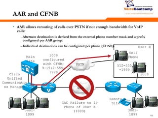
![636363
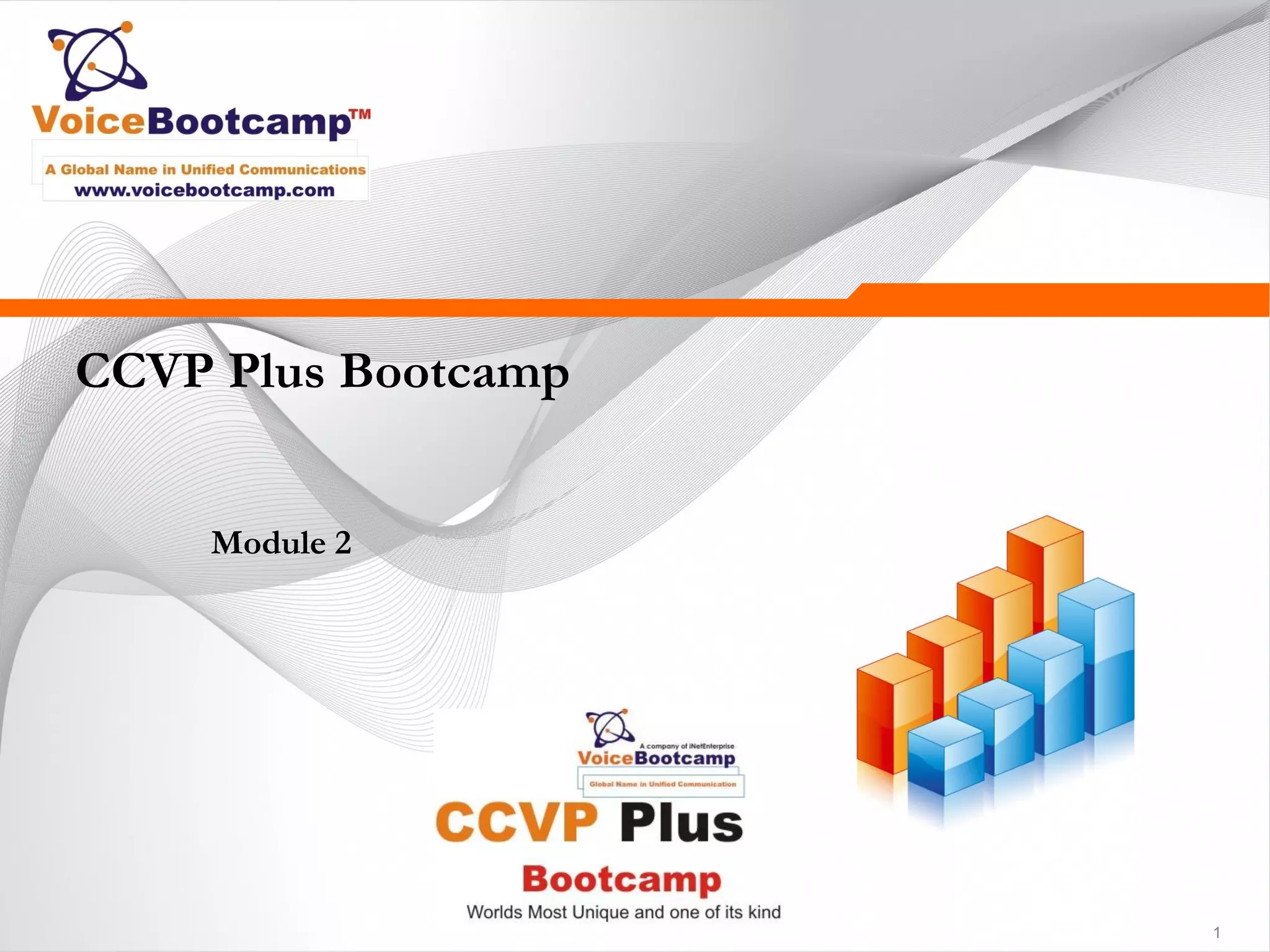
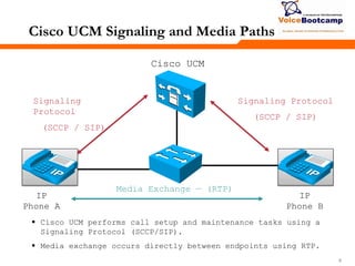
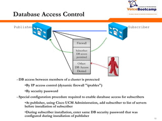
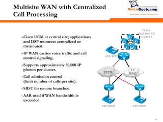
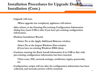
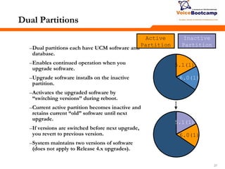
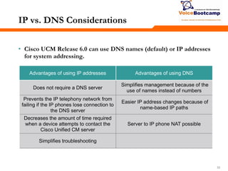
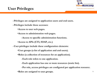
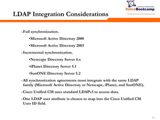
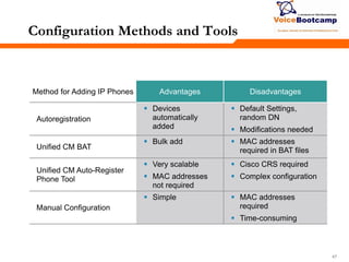
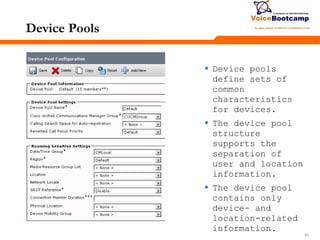
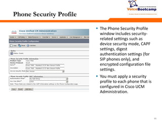
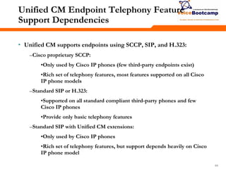
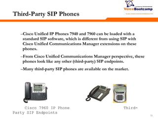
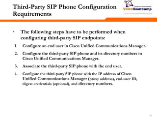
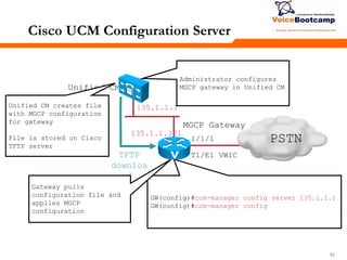
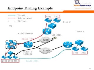
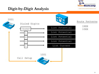
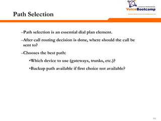
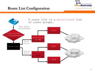
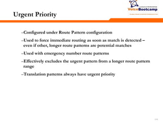
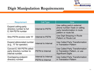
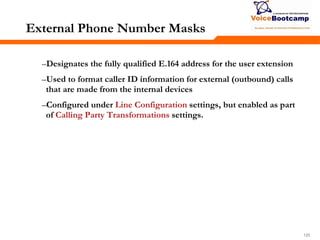
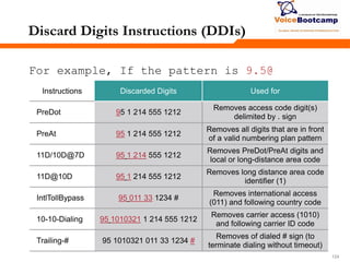
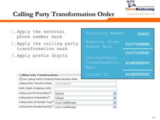
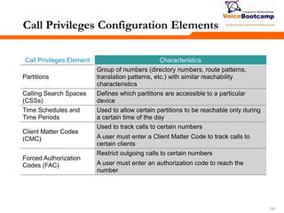
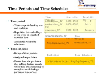
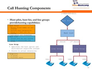
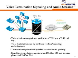
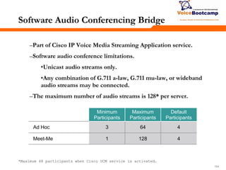
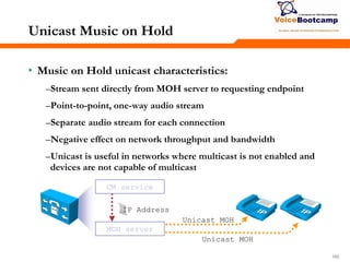
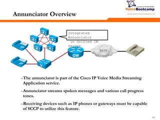
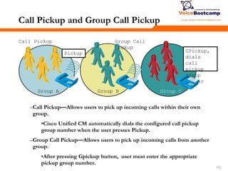
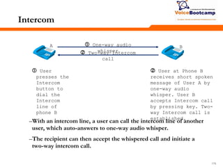
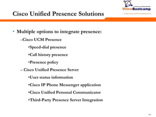
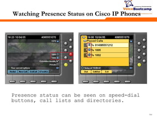
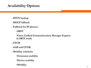
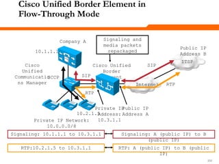
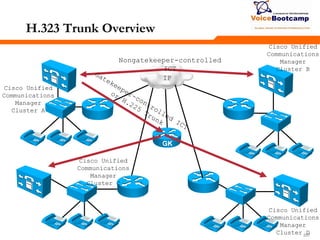
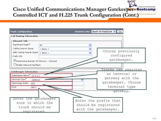
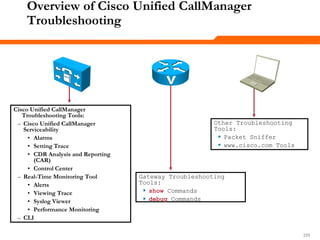
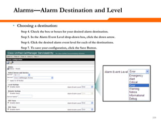
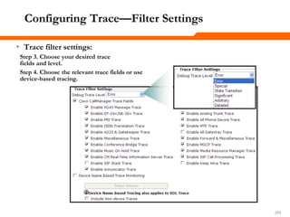
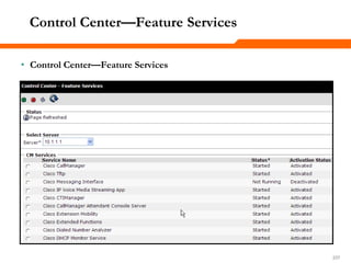
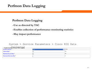
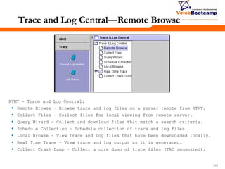
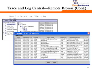
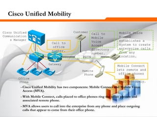
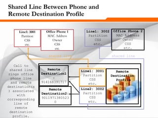
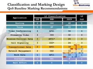
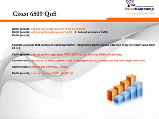
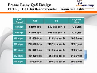
Cisco UCM Endpoint Support
Cisco IP phone models displayed in italic are
end-of-sale.
Cisco Unified IP Phones
(SCCP and SIP)
Type A: 7940, 7960, 7905, 7912
Type B: 7906, 7911, 79[46][125], 797[015]
Cisco softphone Cisco IP Communicator
Other Cisco endpoints
(SCCP only)
7902, 7910, and 7931 (IP phones), 7920 and 7921
(WiFi phones), 7935 and 7936 (conference
stations), 7985 (desktop video phone)
Third-party endpoints
(various)
SCCP: Nokia dual-mode cell phone SCCP client,
Tandberg video endpoints, IP blue VTGO, etc.
SIP: various hard-and software phones
H.323: various hard- and software phones](https://image.slidesharecdn.com/ccvpplusmodule2-140806220156-phpapp02/85/Ccvp-plus-module-2-63-320.jpg)


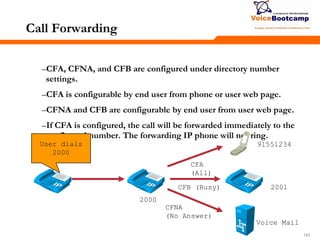
![888888
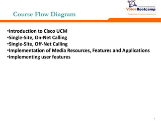
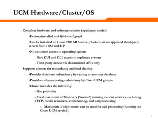
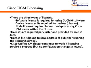
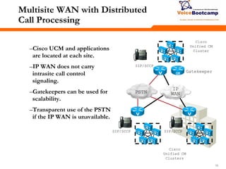
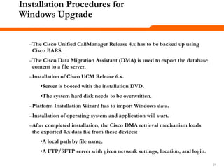
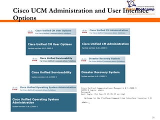
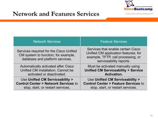
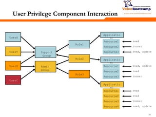
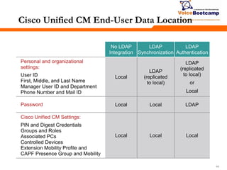
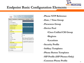
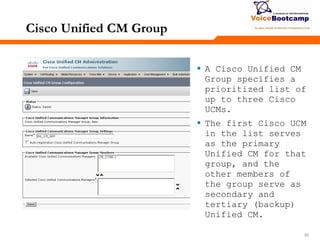
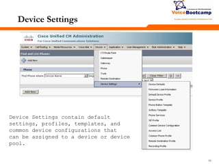
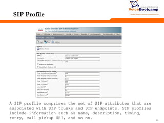
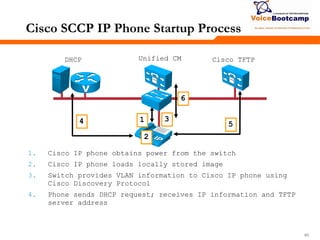
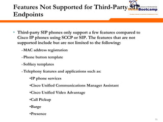
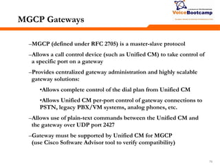
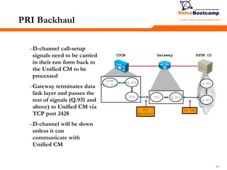
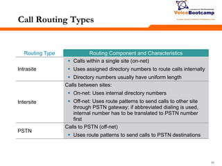
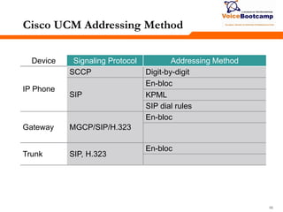
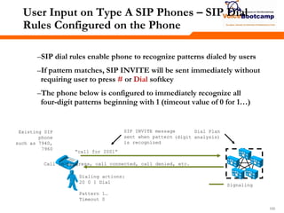
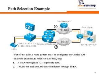
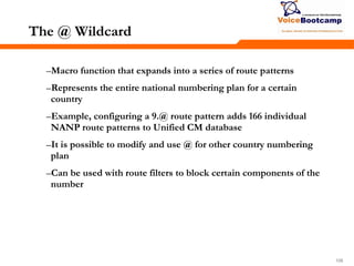
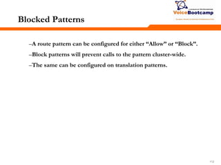
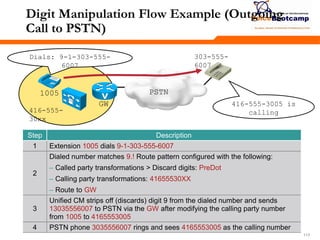
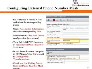
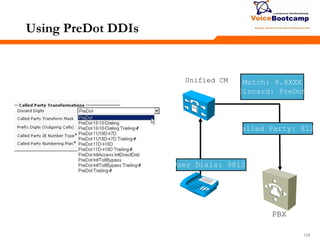
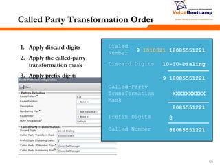
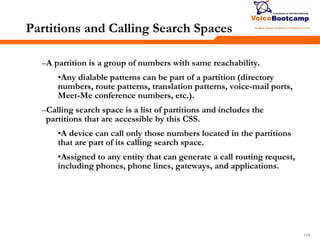
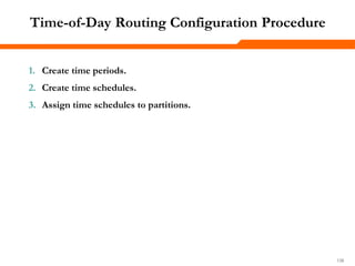
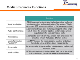
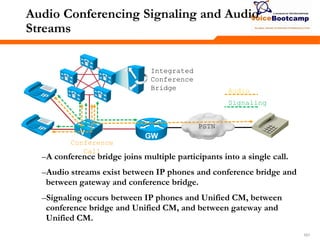
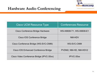
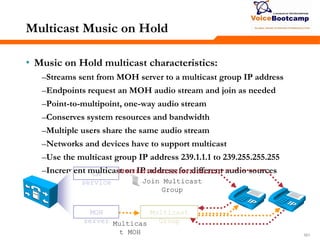
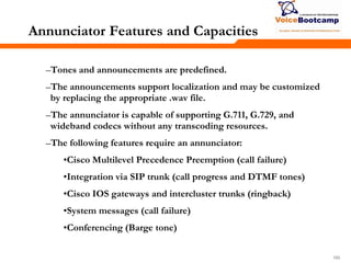
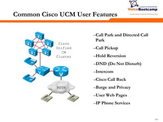
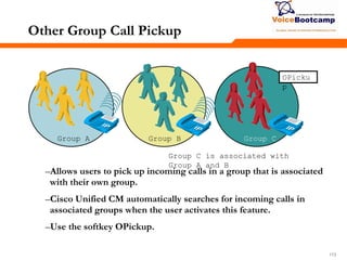
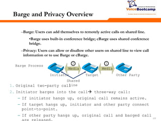
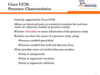
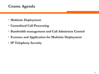
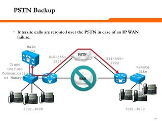
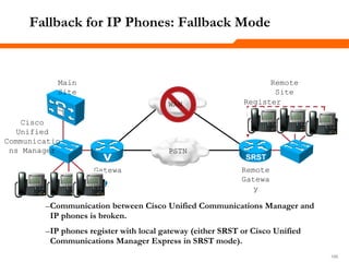
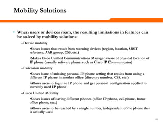
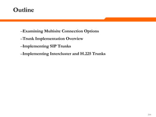
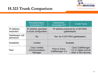
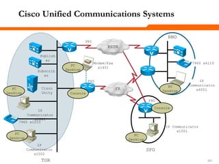
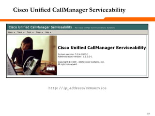
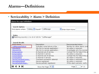
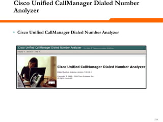
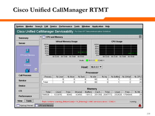
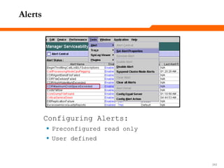
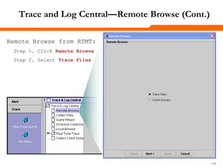
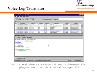
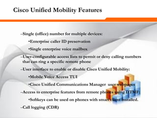
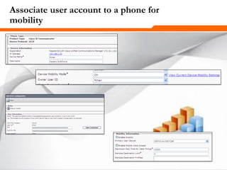
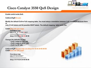
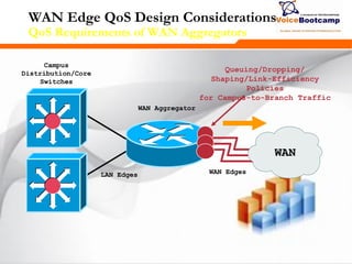
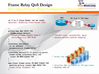
Uniform On-Net Dial Plan Example
Range Use DID Ranges Non-DID Ranges
0XXX
Excluded: 0 is used as Off-
Net access code
1XXX Site A extensions 418 555 1 XXX N/A
2XXX Site B extensions 919 555 2XXX N/A
3XXX Site C extensions 415 555 30XX 3[1-9]XX
4[0-4]XX Site D extensions 613 555 4[0-4]XX N/A
4[5-9]XX Site E extensions 450 555 4[5-9]XX N/A
5XXX Site A extensions 418 555 5XXX N/A
6XXX Site F extensions 514 555 6[0-8]XX 69XX
7XXX Future
8XXX Future
9XXX
Excluded: 9 is used as Off-
Net access code](https://image.slidesharecdn.com/ccvpplusmodule2-140806220156-phpapp02/85/Ccvp-plus-module-2-88-320.jpg)
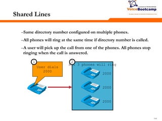
![929292
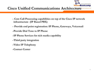
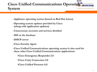
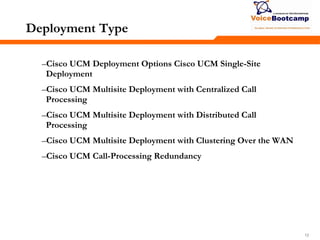
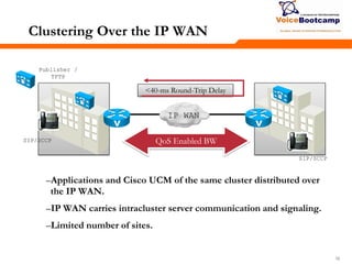
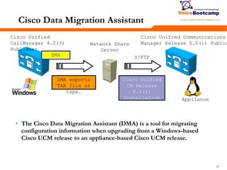
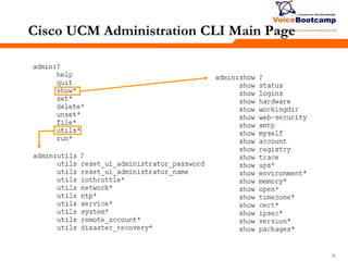
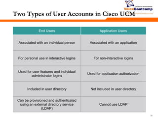
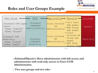
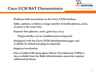
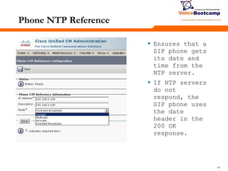
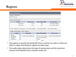
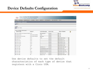
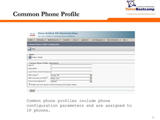
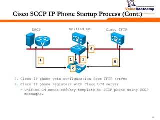
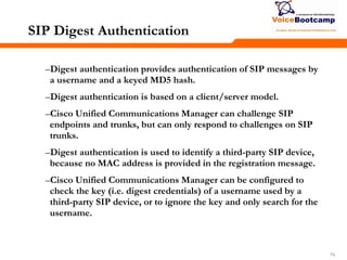
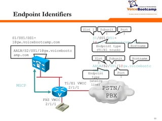
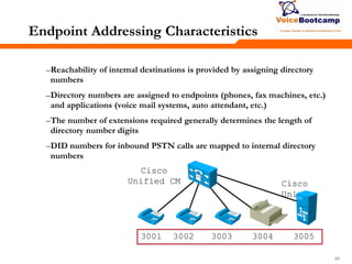
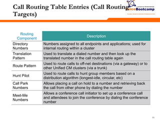
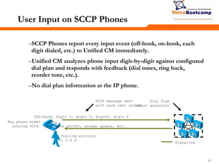
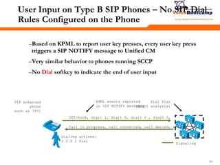
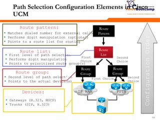
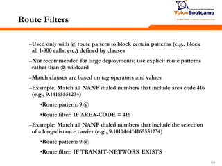
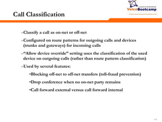
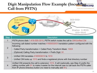
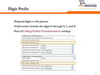
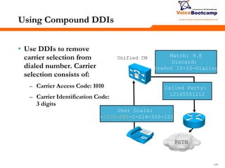
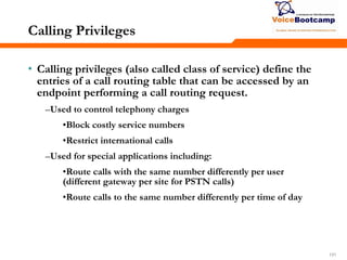
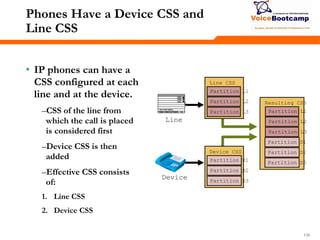
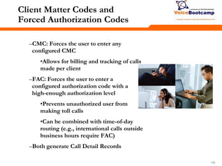
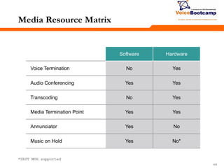
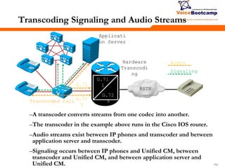
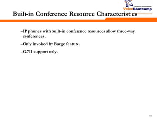
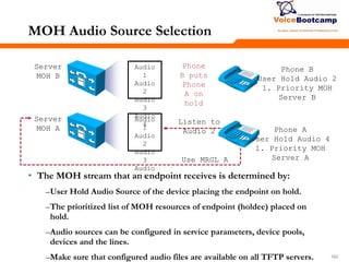
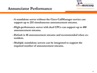
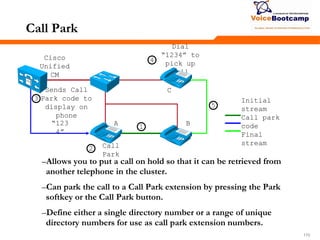
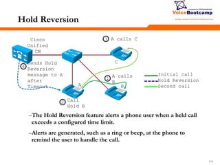
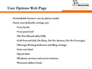
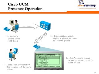
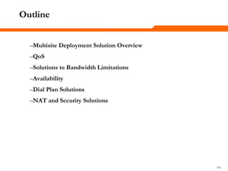
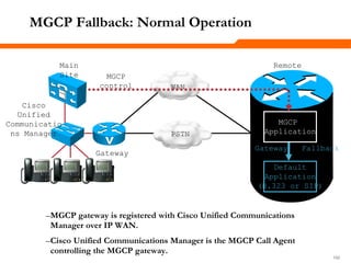
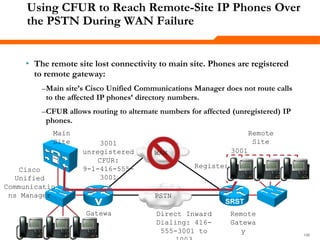
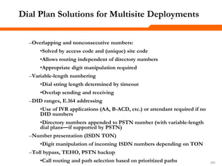
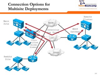
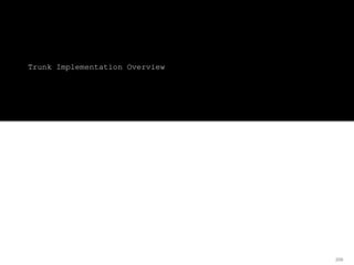
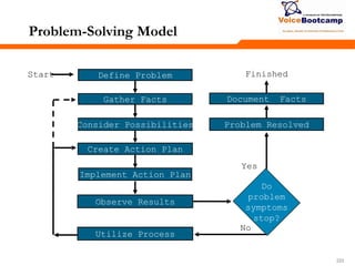
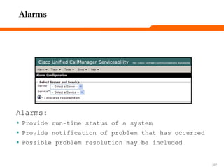
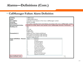
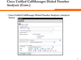
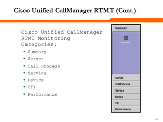
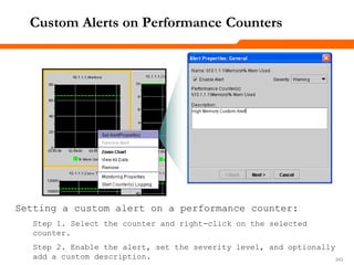
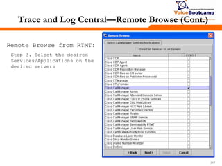
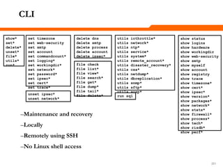
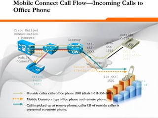
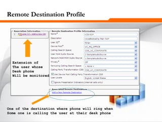
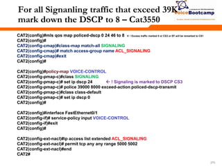
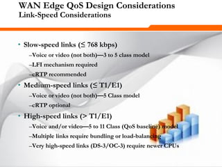
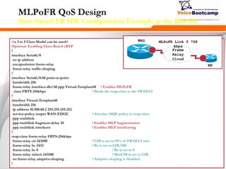
Route Pattern: Commonly Used Wildcards
Wildcard Description
x Single digit (0–9, *, #)
@ North American Numbering Plan
! One or more digits (0–9)
[x-y] Generic range notation
[^x-y] Exclusion range notation
. Terminates access code
# Terminates interdigit timeout
<wildcard>?
Matches zero or more occurrences of any digit that matches the
previous wildcard
<wildcard>+
Matches one or more occurrences of any digit that matches the
previous wildcard](https://image.slidesharecdn.com/ccvpplusmodule2-140806220156-phpapp02/85/Ccvp-plus-module-2-92-320.jpg)
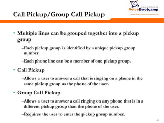
![939393
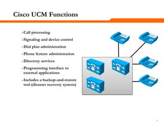
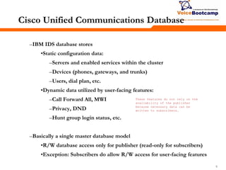
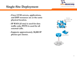
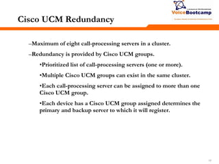
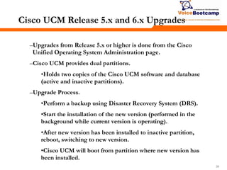
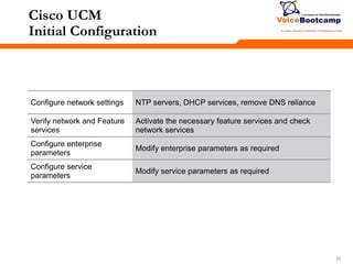
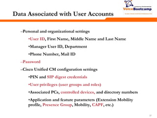
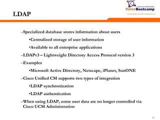
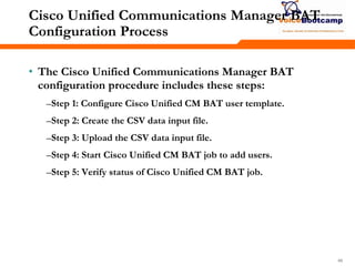
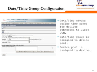
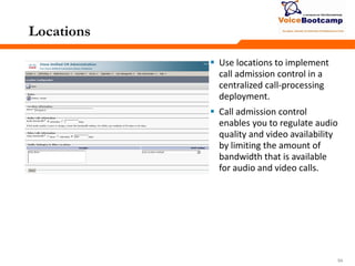
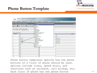
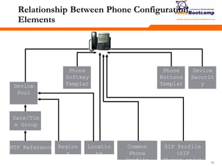
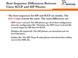
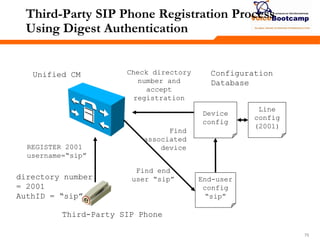
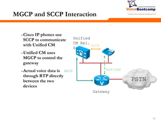
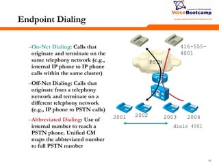
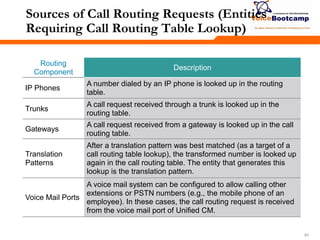
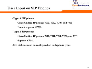
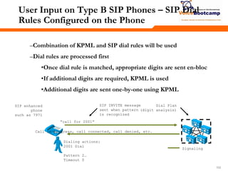
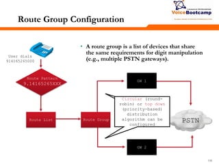
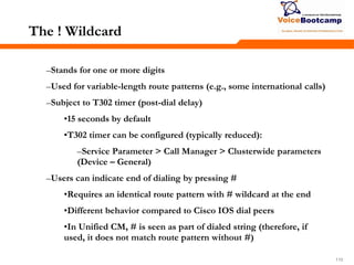
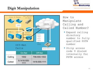
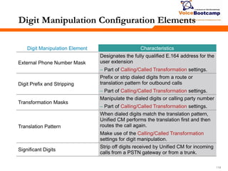
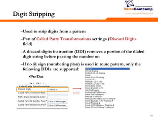
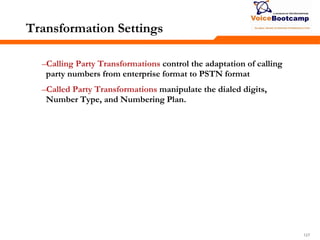
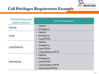
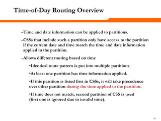
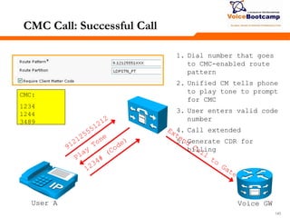
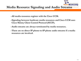
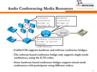
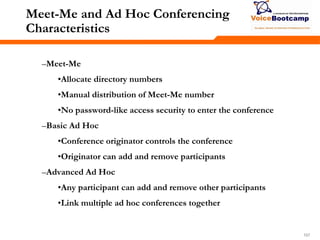
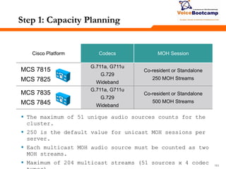
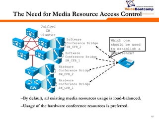
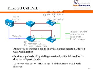
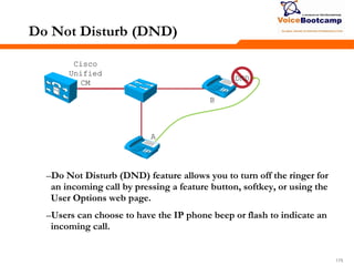
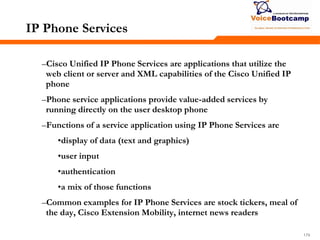
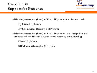
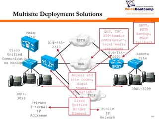
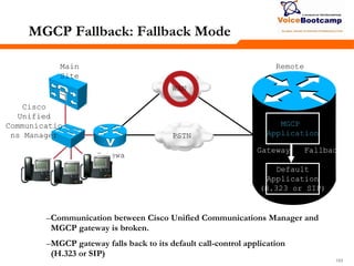
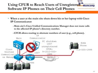
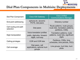
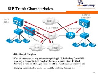
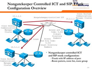
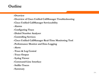
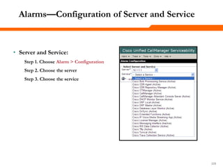
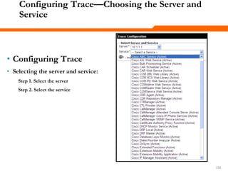
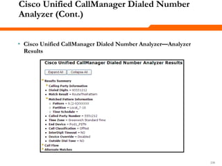
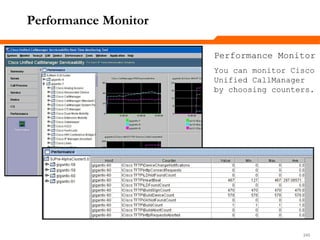
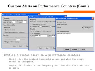
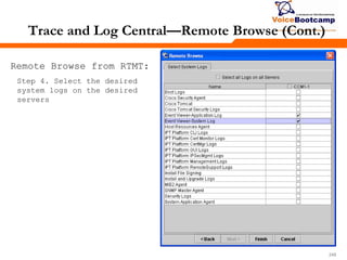
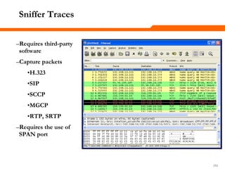
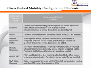
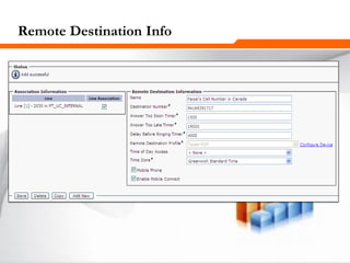
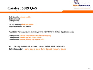
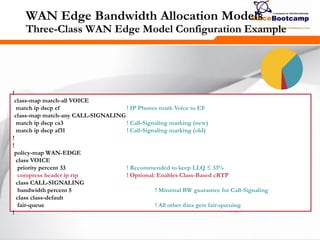
Route Pattern Examples
Pattern Result
1234 Matches 1234
1*1x Matches numbers from 1*10 to 1*19
12xx Matches numbers from 1200 to 1299
13[25-8]6 Matches 1326, 1356, 1366, 1376, 1386
13[^3-9]6 Matches 1306, 1316, 1326, 13*6, 13#6
13!#
Matches any number that begins with 13, is followed by one or
more digits, and ends with #; 135# and 13579# are example
matches](https://image.slidesharecdn.com/ccvpplusmodule2-140806220156-phpapp02/85/Ccvp-plus-module-2-93-320.jpg)
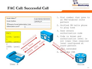
![959595
Digit Collection Example
1111
121X
1[23]XX
131
13!
13[0-4]X
User dial string: Match!
Does not match
Does not match
Does not match
Does not match
Does not match
No other patterns could
match; extend call.
Cisco Unified CM actions:
1111](https://image.slidesharecdn.com/ccvpplusmodule2-140806220156-phpapp02/85/Ccvp-plus-module-2-95-320.jpg)


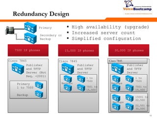
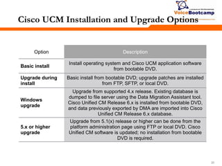
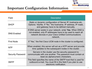
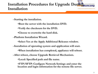
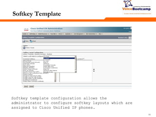
The document provides information about installing and configuring Cisco Unified Communications Manager (UCM): - It describes the basic installation process for UCM, which involves booting from a DVD and running the Platform Installation Wizard. Upgrades can install new software while keeping the existing configuration database. - Important configuration settings that must be specified include DHCP/static networking, DNS, NTP, security password, and SMTP settings for email notifications. - A UCM cluster provides redundancy through multiple call processing servers that devices can register with. The cluster is configured through a shared database for call control data.


![MikroTik Multicast Routing [www.imxpert.co]](https://cdn.slidesharecdn.com/ss_thumbnails/mikrotikmulticastroutingt4t-150218231524-conversion-gate01-thumbnail.jpg?width=640&height=640&fit=bounds)