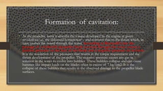
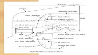
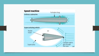
CAVITATION
• INTRODUCTION
• FORMATION OF CAVITIES
• TYPES OF CAVITATION
• EFFECTS OF CAVITATION
• TREAMENT OF CAVITATION
• CAVITATION TUNNEL
• SUPERCAVITATION
Done by,
• JUDITH EROMY.J
INTRODUCTION:
• Rapid formation of vapour bubbles within a
liquid is called cavitation.
• It occurs when the static pressure becomes
smaller than the vapour pressure.
• Cavitation of a ship’s propeller is phenomena
that can greatly reduce a ship propelling
efficiency whilst at the same time lead to rapid
degradation of the propellor.
This Photo by Unknown author is licensed under CC BY-SA.
Formation of cavitation:
• As the propeller turns it absorbs the torque developed by the engine at given
revolutions i.e., the delivered horsepower – and converts that to the thrust which, in
turn, pushes the vessel through the water. According to Bernoulli’s law the
passage of a hydrofoil (propeller blade section) through the water causes a
positive pressure on the face of the blade and a negative pressure on its back.
It is the resolution of the pressures that results in the torque requirement and the
thrust development of the propeller. The negative pressure causes any gas in
solution in the water to evolve into bubbles These bubbles collapse and can cause
hammer like impact loads on the blades often in excess of 7 kg/cm2. It is the
collapse of these bubbles that results in the observed damage to the propeller blade
surfaces.
Types of cavitation:
• In certain conditions, sheet cavitation breaks down
behind the blade into a form known as ‘mist‘ or ‘cloud‘
cavitation.
• ‘Bubble‘ cavitation as the name implies, is the
formation of distinctive bubble cavities.
•
Types of cavitation
• ‘Sheet‘ or ‘Laminar‘ cavitation takes the form
of a thin stationary sheet usually commencing at
the leading edge of the blades.
• ‘Vortex‘ cavitation has the
appearance of a stranded
twisted rope and can be
present at either the blade tips
or the boss.
Effects of Cavitation
• The effects of cavitation may be listed as :
 Reduced Performance
 Blade Erosion
 Vibration
 Noise
Performance
• Cavitation usually starts at the blade tips and
spread gradually over the entire blades as the
propeller loading is increased. When
cavitation has extended to about 0.75 of the
radius it is found there is a considerable loss
in thrust followed by a reduction in torque
which means in practice that, there will be a
marked increase in revolutions for a given
power.
• Since the thrust breakdown proceeds more
rapidly than the change in torque there can be
a considerable loss in efficiency.
EROSION
The tips of the propeller blade and trailing edges are
particularly susceptible to erosion and may be completely
eroded and torn away by the effects of cavitation
Erosion due to cavitation may occur at any part of a
propeller blade where the suction is high but in common
over three significant regions:
At the tip where the rotational speed is highest,
At 0.7 radius where the load is usually at a maximum,
Towards the root of the blade where the sections are
of necessity very thick and the pressure distribution
is adversely affected by the small gap between the
blade
If the cavitation is more extensive or persists for a longer
period of time then it results in serious pitting corrosion of
the metal causing a definite crater or series of craters in the
surface of the blades, leaving the sponge-like appearance
which is characteristics of advanced cavitation erosion
VIBRATION
• Vibration is created due to the unsteady
nature of the cavitation and is termed as the
periodic deflection of the structure in a
vertical, horizontal or torsional manner.
NOISE
• The collapsing cavities give rise to noise
effects which, accompanied by high-frequency
vibrations, can be extremely unpleasant to
passengers and crew if they are situated in the
aft end of ship accommodation
Means of
Avoiding
Cavitation
• Increase the total blade area and thus the thrust
per unit area of blade surface for the same
total thrust.
• Reduce the blade angles and angle of incidence by
adopting slightly larger diameters.
• Vary the pitch over the length of the blade in
order to diminish the loading in critical regions.
• Avoid the occurrence of unduly high sections on
the back of the blades by using section shapes
which give a more uniform distribution of
pressure.
• Design stern to achieve as uniform a wake field as
possible.
Cavitation
number
• A non-dimensional parameter for the dynamic pressure
in a fluid; also to estimate the cavitation probability in
a fluid.
• The onset of cavitation in equipment or components with
flow constrictions can be predicted by calculating
a cavitation number K, defined as below:
• K=2(Pmin−Pvap) /ρv^2
• where
• Pmin: minimum pressure occurring in the vicinity of the
restriction, Pa;
• Pvap: vapor pressure of the liquid, Pa;
• ρ: density of the liquid, kg/m3;
• v: flow velocity through the restriction, m/s.
• A cavitation number of less than 1.5 indicates that
cavitations may occur.
Cavitation tunnel:
• A facility used for propeller cavitation tests. This is a vertical
water circuit with large diameter pipes. A parallel inflow is
established. With or without a ship model, the propeller,
attached to a dynamometer, is brought into the flow, and its
thrust and torque is measured at different ratios of propeller
speed to inflow velocity. To ensure similarity to the full-scale
propeller the pressure in the tunnel is lowered to produce the
correctcavitation number at the propeller axis
Cavitation tunnel
• The cavitation tunnel is a closed
chamber as shown in the figure.
• the model propeller is placed in
a working section in the horizontal
limb
• The working section is provided
with glass viewing ports and is
designed to give uniform flow
across the test section
• A vacuum pump reduces
the pressure in the tunnel
Cavitation tunnel:
• Experiments are usually conducted as follows,
• The water speed is made as high as possible to keep reynold's number high
• The model is made to the largest possible scale considerations
• The shaft revolutions are adjusted to give correct advance coefficient
• Tests can be repeated for many cavitation numbers.
Cavitation tunnel:
• When cavitation is present the propeller can be viewed using a stroboscopic
light set at a frequency which makes the propeller seem stationary to the
human eye.
• Photographs are taken to illustrate the degree of cavitation present
Cavitation tunnel:
• The Cavitation Tunnel at NSTL is one of the most modern and the state of
the art facilities in the world. This is used for study of cavitation inception of
body profile and propellers. It is also used for study of Acoustic
measurements due to cavitation of propellers.
• This facility can provide a water flow speed of 15m/sec and create cavitation
numbers 0.03 to 10. In order to design highly efficient propellers for
applications to naval ships and platforms it is essential to carry out tests on
these propeller models in the cavitation tunnel. The features of cavitation
tunnel are given below
Cavitation bucket
• The combitions of cavitation
number and angle of attack or
advance coefficient for which
cavitation can be expected .
• There will be no cavitation as
long as the
design operates within the
bucket
• The wider the bucket
the greater the range
of angle within the bucket.
Cavitation
• FACE CAVITATION:
• Face propeller cavitation occurs on the driving face of the propeller and is often due to
an incorrect pitch distribution along the length of the blade resulting in the tip pitch being
too small and the blade sections developing a negative angle of attack
• BUBBLE CAVITATION:
• Cavitation erosion (loss of material by mechanical action) occurs when small bubbles filled
with vapor collapse on or near to the surface of the body
• BACK CAVITATION:
• Blade sheet cavitation occurs when large suction pressures build up
near the leading edge of the blade resulting in the back of the blade being
covered with a sheet of bubbles
Supercavitation
• Supercavitation is the use of a cavitation bubble to reduce skin
friction drag on a submerged object and enable high speeds. Applications
include torpedoes and propellers, but in theory, the technique could be
extended to an entire underwater vessel.
Fastest torpedo
VA-111 Shkval
Propellant Solid-fuel
Maximum speed
Launch speed: 50 knots (93 km/h; 58 mph)
Maximum speed: in excess of 200 knots (370
km/h; 230 mph)
Guidance system GOLIS autonomous inertial guidance
Launch platform 533 mm (21 in) torpedo tubes
Fastest torpedo-
va111 shkval
Thank you

cavitation ppt.pptx

  • 1.
    CAVITATION • INTRODUCTION • FORMATIONOF CAVITIES • TYPES OF CAVITATION • EFFECTS OF CAVITATION • TREAMENT OF CAVITATION • CAVITATION TUNNEL • SUPERCAVITATION Done by, • JUDITH EROMY.J
  • 2.
    INTRODUCTION: • Rapid formationof vapour bubbles within a liquid is called cavitation. • It occurs when the static pressure becomes smaller than the vapour pressure. • Cavitation of a ship’s propeller is phenomena that can greatly reduce a ship propelling efficiency whilst at the same time lead to rapid degradation of the propellor. This Photo by Unknown author is licensed under CC BY-SA.
  • 3.
    Formation of cavitation: •As the propeller turns it absorbs the torque developed by the engine at given revolutions i.e., the delivered horsepower – and converts that to the thrust which, in turn, pushes the vessel through the water. According to Bernoulli’s law the passage of a hydrofoil (propeller blade section) through the water causes a positive pressure on the face of the blade and a negative pressure on its back. It is the resolution of the pressures that results in the torque requirement and the thrust development of the propeller. The negative pressure causes any gas in solution in the water to evolve into bubbles These bubbles collapse and can cause hammer like impact loads on the blades often in excess of 7 kg/cm2. It is the collapse of these bubbles that results in the observed damage to the propeller blade surfaces.
  • 4.
    Types of cavitation: •In certain conditions, sheet cavitation breaks down behind the blade into a form known as ‘mist‘ or ‘cloud‘ cavitation. • ‘Bubble‘ cavitation as the name implies, is the formation of distinctive bubble cavities. •
  • 5.
    Types of cavitation •‘Sheet‘ or ‘Laminar‘ cavitation takes the form of a thin stationary sheet usually commencing at the leading edge of the blades.
  • 6.
    • ‘Vortex‘ cavitationhas the appearance of a stranded twisted rope and can be present at either the blade tips or the boss.
  • 8.
    Effects of Cavitation •The effects of cavitation may be listed as :  Reduced Performance  Blade Erosion  Vibration  Noise
  • 9.
    Performance • Cavitation usuallystarts at the blade tips and spread gradually over the entire blades as the propeller loading is increased. When cavitation has extended to about 0.75 of the radius it is found there is a considerable loss in thrust followed by a reduction in torque which means in practice that, there will be a marked increase in revolutions for a given power. • Since the thrust breakdown proceeds more rapidly than the change in torque there can be a considerable loss in efficiency.
  • 10.
    EROSION The tips ofthe propeller blade and trailing edges are particularly susceptible to erosion and may be completely eroded and torn away by the effects of cavitation Erosion due to cavitation may occur at any part of a propeller blade where the suction is high but in common over three significant regions: At the tip where the rotational speed is highest, At 0.7 radius where the load is usually at a maximum, Towards the root of the blade where the sections are of necessity very thick and the pressure distribution is adversely affected by the small gap between the blade If the cavitation is more extensive or persists for a longer period of time then it results in serious pitting corrosion of the metal causing a definite crater or series of craters in the surface of the blades, leaving the sponge-like appearance which is characteristics of advanced cavitation erosion
  • 11.
    VIBRATION • Vibration iscreated due to the unsteady nature of the cavitation and is termed as the periodic deflection of the structure in a vertical, horizontal or torsional manner.
  • 12.
    NOISE • The collapsingcavities give rise to noise effects which, accompanied by high-frequency vibrations, can be extremely unpleasant to passengers and crew if they are situated in the aft end of ship accommodation
  • 13.
    Means of Avoiding Cavitation • Increasethe total blade area and thus the thrust per unit area of blade surface for the same total thrust. • Reduce the blade angles and angle of incidence by adopting slightly larger diameters. • Vary the pitch over the length of the blade in order to diminish the loading in critical regions. • Avoid the occurrence of unduly high sections on the back of the blades by using section shapes which give a more uniform distribution of pressure. • Design stern to achieve as uniform a wake field as possible.
  • 14.
    Cavitation number • A non-dimensionalparameter for the dynamic pressure in a fluid; also to estimate the cavitation probability in a fluid. • The onset of cavitation in equipment or components with flow constrictions can be predicted by calculating a cavitation number K, defined as below: • K=2(Pmin−Pvap) /ρv^2 • where • Pmin: minimum pressure occurring in the vicinity of the restriction, Pa; • Pvap: vapor pressure of the liquid, Pa; • ρ: density of the liquid, kg/m3; • v: flow velocity through the restriction, m/s. • A cavitation number of less than 1.5 indicates that cavitations may occur.
  • 15.
    Cavitation tunnel: • Afacility used for propeller cavitation tests. This is a vertical water circuit with large diameter pipes. A parallel inflow is established. With or without a ship model, the propeller, attached to a dynamometer, is brought into the flow, and its thrust and torque is measured at different ratios of propeller speed to inflow velocity. To ensure similarity to the full-scale propeller the pressure in the tunnel is lowered to produce the correctcavitation number at the propeller axis
  • 16.
    Cavitation tunnel • Thecavitation tunnel is a closed chamber as shown in the figure. • the model propeller is placed in a working section in the horizontal limb • The working section is provided with glass viewing ports and is designed to give uniform flow across the test section • A vacuum pump reduces the pressure in the tunnel
  • 17.
    Cavitation tunnel: • Experimentsare usually conducted as follows, • The water speed is made as high as possible to keep reynold's number high • The model is made to the largest possible scale considerations • The shaft revolutions are adjusted to give correct advance coefficient • Tests can be repeated for many cavitation numbers.
  • 18.
    Cavitation tunnel: • Whencavitation is present the propeller can be viewed using a stroboscopic light set at a frequency which makes the propeller seem stationary to the human eye. • Photographs are taken to illustrate the degree of cavitation present
  • 19.
    Cavitation tunnel: • TheCavitation Tunnel at NSTL is one of the most modern and the state of the art facilities in the world. This is used for study of cavitation inception of body profile and propellers. It is also used for study of Acoustic measurements due to cavitation of propellers. • This facility can provide a water flow speed of 15m/sec and create cavitation numbers 0.03 to 10. In order to design highly efficient propellers for applications to naval ships and platforms it is essential to carry out tests on these propeller models in the cavitation tunnel. The features of cavitation tunnel are given below
  • 20.
    Cavitation bucket • Thecombitions of cavitation number and angle of attack or advance coefficient for which cavitation can be expected . • There will be no cavitation as long as the design operates within the bucket • The wider the bucket the greater the range of angle within the bucket.
  • 21.
    Cavitation • FACE CAVITATION: •Face propeller cavitation occurs on the driving face of the propeller and is often due to an incorrect pitch distribution along the length of the blade resulting in the tip pitch being too small and the blade sections developing a negative angle of attack • BUBBLE CAVITATION: • Cavitation erosion (loss of material by mechanical action) occurs when small bubbles filled with vapor collapse on or near to the surface of the body • BACK CAVITATION: • Blade sheet cavitation occurs when large suction pressures build up near the leading edge of the blade resulting in the back of the blade being covered with a sheet of bubbles
  • 23.
    Supercavitation • Supercavitation isthe use of a cavitation bubble to reduce skin friction drag on a submerged object and enable high speeds. Applications include torpedoes and propellers, but in theory, the technique could be extended to an entire underwater vessel.
  • 25.
    Fastest torpedo VA-111 Shkval PropellantSolid-fuel Maximum speed Launch speed: 50 knots (93 km/h; 58 mph) Maximum speed: in excess of 200 knots (370 km/h; 230 mph) Guidance system GOLIS autonomous inertial guidance Launch platform 533 mm (21 in) torpedo tubes
  • 26.
  • 27.